

Page 1
GB
BU 0750
NORDAC SK 750E
Manual for Frequency inverters
Page 2

NORDAC SK 750E Manual Safety information
SK 750E Frequency Inverter
Safety and operating instructions for
drive power converters
(as per: Low Voltage Directive 2006/95/EEC )
1. General
During operation, drive power converters may, depending on their
protection class, have live, bare, moving or rotating parts or hot
surfaces.
Unauthorised removal of covers, improper use, incorrect installation
or operation causes a risk of serious personal injury or material
damage.
Further information can be found in this documentation.
All transportation, installation, initialisation and maintenance work
must be carried out by qualified personnel (compliant with
IEC 364, CENELEC HD 384, DIN VDE 0100, IEC 664 or DIN
VDE 0110, and national accident prevention regulations).
For the purposes of these basic safety instructions, qualified
personnel are persons who are familiar with the assembly,
installation, commissioning and operation of this product and who
have the relevant qualifications for their work.
2. Proper use in Europe
Drive power converters are components intended for installation in
electrical systems or machines.
When installed in machines, the drive power converter cannot be
commissioned (i.e. commencement of the proper use) until it has
been ensured that the machine meets the provisions of the
EC Directive 2006/42/EEC (Machine Directive); EN 60204 must also
be complied with.
Commissioning (i.e. implementation of the proper use) is only
permitted if the EMC Directive (2004/108/EEC) is complied with.
Drive power converters with the CE mark meet the requirements of
the Low Voltage Directive 2006/95/EEC. The harmonized standards
stated in the Declaration of Conformity are used for the drive power
converters.
Technical data and information for connection conditions can be
found on the name plate and in the documentation, and must be
complied with.
The drive power converters may only be used for the safety
functions which are described and for which they have been
explicitly approved.
3. Transport, storage
Information regarding transport, storage and correct handling must
be complied with.
4. Installation
The installation and cooling of the equipment must be implemented
according to the regulations in the corresponding documentation.
The drive power converters must be protected against
impermissible loads. Especially during transport and
handling, components must not be deformed and/or
insulation distances must not be changed. Touching of
electronic components and contacts must be avoided.
Drive power converters have electrostatically sensitive
components, which can be easily damaged by incorrect
handling. Electrical components must not be mechanically
damaged or destroyed (this may cause a health hazard!).
5. Electrical connections
When working on live drive power converters, the applicable
national accident prevention regulations must be complied
with (e.g. VBG A3, formerly VBG 4).
The electrical installation must be implemented according to
the applicable regulations (e.g. cable cross-section, fuses,
ground lead connections). Further information is contained
in the documentation.
Information about EMC-compliant installation – such as
shielding, earthing, location of filters and installation of
cables can be found in the drive power converter
documentation. These instructions must be complied with
even with CE marked drive power converters. Compliance
with the limiting values specified in the EMC regulations is
the responsibility of the manufacturer of the system or
machine.
6. Operation
Where necessary, systems where drive power converters
are installed must be equipped with additional monitoring
and protective equipment according to the applicable safety
requirements, e.g. legislation concerning technical
equipment, accident prevention regulations, etc.
The parameterisation and configuration of the drive power
converter must be selected so that no hazards can occur.
All covers must be kept closed during operation.
7. Maintenance and repairs
After the drive power converter is disconnected from the
power supply, live equipment components and power
connections should not be touched immediately, because of
possible charged capacitors. Observe the relevant
information signs located on the drive power converter.
Further information can be found in this documentation.
These safety instructions must be kept in a safe place!
2 BU 0750 GB-3311
Page 3

NORDAC SK 750E Manual Concerning this document
Designation of previous issues
SW status
Comments
BU 0750 GB, December 2004
V 3.1 R1
First issue based on BU 0700 DE
BU 0750 GB, December 2005
V 3.1 R2
Revision, supplementation and correction
BU 0750 GB, April 2006
V 3.2 R0
Revision, wall-mounting kit, motor mounting,
differentiation of the options for IP54 and IP65
version, cable glands
BU 0750 GB, March 2007
Part No.: 6077502 / 1207
V 3.2 R0
Data backup via P550 only right hand slot, Section 3.2
right / left slot
BU 0750 GB, March 2008
Part No.: 6077502 / 1208
V3.4 R4
Control for electromagnetic motor brakes, P217,
P426, P533, P535
BU 0750 GB, August 2011
Part No.: 6077502 / 3311
V3.5 R1
Addition of UL-relevant details; revision of Sections
2.6, 3.3.3, 3.3.4; revision of parameter P208, P215;
P216, function of digital inputs: 47/48;
addition of environmental classes, long-term storage
and min. brake resistances (Section 9)
Documentation
Designation: BU 0750 EN
Part No.: 607 75 01
Device series: SK 750E
Version list
Publisher
Getriebebau NORD GmbH & Co. KG
Rudolf-Diesel-Str. 1 D-22941 Bargteheide http://www.nord.com/
Tel.: +49 (0) 45 32 / 401-0 Fax +49 (0) 45 32 / 401-555
Intended use of the
frequency inverter
Compliance with the operating instructions is necessary for fault-free operation and the
acceptance of any warranty claims. These operating instructions must be read before
working with the device!
These operating instructions contain important information about servicing. They must
therefore be kept near to the device .
SK 750E frequency inverters are devices for industrial and commercial plants for operating
three-phase asynchronous motors with squirrel-cage rotors. These motors must be suitable for
operation with frequency inverters, other loads must not be connected to the devices.
SK 750E frequency inverters are devices for fixed installation in control cabinets. All details
regarding technical data and permissible conditions at the installation site must be complied
with.
Commissioning (commencement of the intended use) is prohibited until it has been ensured that
the machine complies with the EMC Directive 2004/108/EEC and that the conformity of the end
product meets the Machinery Directive 2006/42/EEC (observe EN 60204).
Getriebebau NORD GmbH & Co. KG, 2011
BU 0750 GB-3311 3
Page 4

NORDAC SK 750E Manual
1 GENERAL INFORMATION .......................................................................................................... 6
2 ASSEMBLY AND INSTALLATION ............................................................................................ 13
1.1 Overview ................................................................................................................... 6
1.2 Delivery ..................................................................................................................... 6
1.3 Scope of supply ........................................................................................................ 7
1.4 Safety and installationinformation ............................................................................ 8
1.5 Certifications ............................................................................................................. 9
1.5.1 UL and cUL certification ................................................................................... 9
1.5.2 European EMC Directive ................................................................................ 10
1.6 Nomenclature / Type code ..................................................................................... 11
1.7 Version with protection class IP54 / IP65 ............................................................... 12
2.1 Motor-integrated and close to motor layouts .......................................................... 13
2.2 Installation .............................................................................................................. 14
2.3 Dimensions of the SK 750E ................................................................................... 15
2.4 Attachment accessories for the SK 750E ............................................................... 16
2.5 SK 750E wall mounting kit ...................................................................................... 16
2.5.1 Dimensions of the SK 750E with wall mounting kit ........................................ 17
2.6 Mounting of the SK750E directly on a motor .......................................................... 18
2.7 Wiring guidelines .................................................................................................... 19
2.8 Electrical Connection .............................................................................................. 20
2.9 Electrical connection of power unit ......................................................................... 20
2.9.1 Mains supply (PE, L1, L2, L3) ........................................................................ 22
2.9.2 Electromagnetic brake (+Br, -Br, PE) ............................................................. 22
2.9.3 Brake resistor (+B, -B, PE) ............................................................................. 22
2.9.4 Motor cable (U, V, W, PE) .............................................................................. 22
2.9.5 Temperature sensor (T1, T2) ......................................................................... 23
2.9.6 PowerConnection Terminals .......................................................................... 23
2.9.7 Control connections (optional) ....................................................................... 24
2.9.8 Cable connections .......................................................................................... 25
3 OPTIONS .................................................................................................................................... 26
3.1 Modular options ...................................................................................................... 26
3.2 Overview of Technology Units ................................................................................ 27
3.2.1 Installing the Technology Unit ........................................................................ 29
3.2.2 ControlBox SK TU2-CTR ............................................................................... 30
3.2.3 PotentiometerBox SK TU2-POT .................................................................... 35
3.2.4 DeviceNet Module SK TU2-DEV .................................................................... 35
3.2.5 Profibus Module SK TU2-PBR ....................................................................... 36
3.2.6 CANopen BUS Module SK TU2-CAO ............................................................ 36
3.2.7 InterBus Module SK TU2-IBS ........................................................................ 37
3.2.8 AS interface SK TU2-AS1 .............................................................................. 37
3.2.9 Retrofit kit, SK TU2 cover ............................................................................... 38
3.3 Customer unit overview .......................................................................................... 39
3.3.1 Installation of customer units .......................................................................... 40
3.3.2 Removal of Customer Units ........................................................................... 41
3.3.3 Customer unit Basic I/O ................................................................................. 42
3.3.4 Customer unit Standard I/O............................................................................ 43
3.3.5 Multi I/O Customer Unit .................................................................................. 44
3.3.6 Multi I/O 20mA Customer Unit........................................................................ 45
3.3.7 BUS Customer Units, SK CU1-CAN-RJ, SK CU1-PBR ................................. 46
3.4 Overview of Special Extensions ............................................................................. 47
3.4.1 Installation of the special extension units ....................................................... 48
3.4.2 Removal of Special Extensions ...................................................................... 49
3.4.3 Special Extension Encoder I/O ...................................................................... 50
3.4.4 Special Extension PosiCon I/O ...................................................................... 51
3.5 Control Terminals of Customer I/Os ....................................................................... 52
3.6 Colour and contact assignments for the incremental encoders ............................. 54
4 BU 0750 GB-3311
Page 5

Table of Contents
4 OPERATION AND DISPLAY ...................................................................................................... 55
4.1 Control element connection variants ...................................................................... 56
4.2 ParameterBox, Handheld Version, SK PAR-2H ..................................................... 57
4.3 ParameterBox Installation Version, SK PAR-2E .................................................... 58
4.3.1 Electrical connection ...................................................................................... 59
4.4 Functions of the ParameterBox .............................................................................. 60
4.5 Parameters of the ParameterBox ........................................................................... 67
4.6 ParameterBox error messages .............................................................................. 70
4.7 Data transfer with NORD CON ............................................................................... 73
5 NORD CON SOFTWARE ........................................................................................................... 74
5.1 General Information ................................................................................................ 74
6 COMMISSIONING ....................................................................................................................... 76
6.1 Basic settings ......................................................................................................... 76
6.2 Basic operation - Quick start guide ........................................................................ 77
6.3 Minimum configuration of control connections ....................................................... 78
7 PARAMETERISATION ............................................................................................................... 79
7.1 Array parameter display ......................................................................................... 80
7.2 Operating displays .................................................................................................. 81
7.3 Basic parameters .................................................................................................... 82
7.4 Motor data / characteristic curve parameters ......................................................... 87
7.5 Speed control ......................................................................................................... 90
7.6 Control clamps ........................................................................................................ 94
7.7 Extra functions ...................................................................................................... 109
7.8 PosiCon ................................................................................................................ 119
7.9 Information ............................................................................................................ 120
7.10 Parameter overview, User settings .................................................................... 126
8 ERROR MESSAGES ................................................................................................................ 133
8.1 ControlBox display ................................................................................................ 133
9 TECHNICAL DATA ................................................................................................................... 139
9.1 General Data ........................................................................................................ 139
9.2 Electrical Data 230V ............................................................................................. 140
9.3 Electrical data 400V .............................................................................................. 140
9.4 Electrical data for UL/cUL certification ................................................................. 141
10 ADDITIONAL INFORMATION ................................................................................................ 142
10.1 Setpoint processing in the SK 750E ................................................................... 142
10.2 PID controller for the SK 750E ........................................................................... 144
10.3 Process controller ............................................................................................... 146
10.3.1 Process controller application example ...................................................... 146
10.3.2 Process controller parameter settings ........................................................ 147
10.4 Electromagnetic compatibility (EMC) ................................................................. 148
10.5 EMC limit value classes...................................................................................... 148
10.6 Maintenance and servicing information .............................................................. 150
10.6.1 Maintenance Instructions ........................................................................... 150
10.6.2 Repair information ...................................................................................... 151
11 KEYWORD INDEX .................................................................................................................. 152
BU 0750 GB-3311 5
Page 6

NORDAC SK 750E Manual
1 General information
The NORDAC SK 750E series is based on the proven SK 700E series. However, it is designed for use in
harsher ambient conditions (up to 60°C, at least IP54). These devices are characterised by the high modularity
and excellent control characteristics.
These devices are provided with sensorless vector current control system which in combination with
asynchronous three-phase motor types constantly ensures an optimised voltage-to-frequency ratio. This has
the following significance for the drive: Peak start-up and overload torques at constant speed.
Due to its modular construction, the variously combinable technology units, customer units and special
extension units, this device series is suitable for all possible applications.
Due to the wide range of setting options, these inverters are capable of controlling all three-phase motors. The
power range is from 5.5kW to 22kW (3~ 400V...480V) and 5.5 to 11kW (3~ 200…240V) with integrated line
filter. The overload capacity of these devices is 150% for 60 seconds and 200% for 3.5 seconds.
This manual is based on the device software V3.5R1 (P707) for the SK 750E. If the frequency inverter used
has a different version, this may lead to some differences. If necessary, you can download the current manual
from the Internet (http://www.nord.com/).
1.1 Overview
Properties of the basic device:
High starting torque and precise motor speed control setting with sensorless current vector control
Can be mounted next to each other without additional spacing
Permissible environmental temperature range: 0 to 50°C (or up to 60°C please refer to the technical
data)
Integrated EMC line filter for limit curve A as per EN55011
Automatic measurement of the stator resistance
Programmable direct current braking
Integrated brake chopper for 4 quadrant drive
Integrated RS485 interface on M12 socket
Four separate online switchable parameter sets
High protection class IP54 (air cooling), IP65 with water cooled version (special version)
NOTE: The characteristics of the basic device with an additional technology unit, customer unit or special
extension are described in Section 3 „Options„.
1.2 Delivery
Check the equipment immediately after delivery/unpacking for transport damage such as deformation or loose
parts.
If there is any damage, contact the carrier immediately and carry out a thorough assessment.
Important! This also applies even if the packaging is undamaged.
6 Subject to technical amendments BU 0750 GB-3311
Page 7

1. General information
NOTE:
Additional bus manuals are available –
BU 0020 … BU 0090..
>>> www.nord.com <<<
1.3 Scope of supply
Standard version: State the protection class, IP54 (air cooling) / (IP65 water cooling as special
version)
→ when ordering!
Integrated brake chopper
Integrated EMC line filter for limit curve A as per EN55011
Blank cover for the 1st and 2nd technology unit slots
Shield angle
Operating Instructions
Available accessories: Brake resistor with high protection class on request, otherwise as for SK 700E
(IP20)
Interface converter RS232 RS485 (additional description BU 0010)
NORD CON, PC parameterisation software > www.nord.com <
ParameterBox, external control panel with LCD plain text display, connection cable
(supplementary description BU 0040 DE)
Technology Unit:
SK TU2-CTR, ControlBox
detachable control panel, 4 figure 7 segment LED display, keyboard
SK TU2-POT, PotentiometerBox
Additional module with switch (R/L) and infinitely variable potentiometer
SK TU2-PBR, Profibus, additional module for Profibus communication (1.5MBaud)
SK TU2-PBR-24V, with external 24V supply (12MBaud)
SK TU2-PBR-KL, Connection to terminal bar with cover (1.5MBaud)
SK TU2-CAN, CANbus, additional module for CANbus communication
SK TU2-CAO, CANopen, bus switching
SK TU2-DEV, DeviceNet, bus switching
SK TU2-IBS, InterBus, bus switching
SK TU2-AS1, AS interface, bus switching
Customer interfaces:
SK CU1-BSC, basic I/O, limited scope for signal processing
SK CU1-BSC, standard I/O, moderate scope for signal processing
SK CU1-MLT, multi-I/O, high level of scope for signal processing
SK CU1-MLT-20mA, multi-I/O, high level of scope for signal processing
SK CU1-CAN, CANbus I/O, bus switching via the CANbus
SK CU1-PBR, Profibus I/O, bus switching via Profibus DP
Special extension units:
SK XU1-POS, PosiCon I/O, positioning module
(Supplementary instruction BU 0710 GB)
SK XU1-ENC, Encoder I/O, incremental encoder input for speed control
BU 0750 GB-3311 Subject to technical amendments 7
Page 8
NORDAC SK 750E Manual
CAUTION
The heat sink and all other metal components can heat up to temperatures above 70°C.
When mounting, sufficient distance from neighbouring components must be maintained.
When working on the components, allow sufficient cooling time before starting work.
ATTENTION
DANGER TO LIFE
The power unit can continue to carry voltages for up to 5 minutes after being switched off at
the mains. Inverter terminals, motor cables and motor terminals may carry voltage!
Touching open or free terminals, cables and equipment components can lead to severe injury
or death!
Work may only be carried out by qualified electricians and with the electrical supply to the
equipment disconnected.
1.4 Safety and installationinformation
NORDAC SK 750E frequency inverters are devices for use in industrial high voltage systems and are operated
at voltages which could lead to severe injuries or death if they are touched.
Installation and other work may only be carried out by qualified electricians and with the device
disconnected. The operating instructions must always be available to these persons and must be
strictly observed.
Local regulations for the installation of electrical equipment and accident prevention must be complied
with.
The equipment continues to carry hazardous voltages for up to 5 minutes after being switched off at
the mains. The equipment may only be opened or the cover or control element removed 5 minutes
after the equipment has been disconnected from the power supply. All covers must be put back in
place before the line voltage is switched back on again.
For safe isolation from the mains, all poles of the supply cable to the frequency inverter must be able
to be disconnected.
Even during motor standstill (e.g. caused by a release block, blocked drive or output terminal short
circuit), the line connection terminals, motor terminals and braking resistor terminals may still conduct
hazardous voltages. A motor standstill is not identical to electrical isolation from the mains.
Caution, even parts of the control card and, in particular, the connection plug for the removable
technology units can conduct hazardous voltages. The control terminals are mains voltage free.
Caution, with certain settings, the frequency inverter/motor can start up automatically after the mains
are switched on.
The circuit boards contain highly-sensitive MOS semiconductor components that are particularly
sensitive to static electricity. Avoid touching circuit tracks and components with the hand or metallic
objects. Only the terminal strip screws may be touched with insulated screwdrivers when connecting
the cables.
The frequency inverter is only intended for permanent connection and may not be operated without
effective earthing connections which comply with local regulations for large leakage currents
(> 3.5mA). VDE 0160 stipulates the installation of a second earthing conductor or an earthing
conductor cross-section of at least 10 mm2.
In case of three-phase frequency inverters, common ground-fault circuit interrupters are not suitable
only for protection if the local regulations do not permit possible DC components in the leakage
current. The standard FI circuit breaker must comply with the new design as per VDE 0664.
In normal use, NORDAC SK 750E frequency inverters are maintenance free. The cooling surfaces
must be regularly cleaned with compressed air if the ambient air is dusty.
8 Subject to technical amendments BU 0750 GB-3311
Page 9

CAUTION
Children and the general public must be kept away from the equipment!
The equipment may only be used for the purpose intended by the manufacturer. Unauthorised
modifications and the use of spare parts and additional equipment which has not been
purchased from or recommended by the manufacturer of the device may cause fire, electric
shock and injury.
Keep these operating instructions in an accessible location and give them to all operators!
WARNING
This is a product with a restricted sale class as per IEC 61800-3. In a domestic environment this
product may cause high frequency interference, in which case the operator may be required to take
suitable measures.
An appropriate measure would be the inclusion of a recommended line filter.
UL File: E171342
1.5 Certifications
1.5.1 UL and cUL certification
(Use in North America)
“Suitable for use on a circuit capable of delivering not more than
5000 rms symmetrical amperes, 200…240 Volts or
380…480 Volts (three phase)” and “when protected by J class
fuses.” as indicated."
Suitable for use on a circuit capable of delivering not more than
5000A (symmetrical), 200...240V or 380...460 Volts (three
phase) and when protected by "J class fuses" as described in
Section 9.4.
NORDAC SK 750E frequency inverters have a motor overload
protection. Further technical details can be found in Section 9,
"Technical Data".
“Relays on extension units and customer interface units may
only be used at 230V ac maximum, same phase only.”
The relays of the extension units and customer interface units may only be used at max. 230V ac. The same
polarity must be used for all relays.
„Use 75°C Copper Conductor Only, Maximum Surrounding Air Temperature 50°C.”
"Copper cable with an insulation rating of at least 75°C must be used for connection. A maximum ambient
temperature of 50°C must be maintained.
Frequency inverter size1:
„The torque value for the field wiring terminals for mains circuit terminals and motor terminals must be 10.62 … 13.27 lb-in
(1.2 … 1.5Nm). The torque value for the supplemental terminal blocks, external brake resistor and thermal sensor must be
4.42 … 5.31 lb-in (0.5 … 0.6Nm).”
Frequency inverter size 1:
The tightening torque value for the terminals the mains and motor cables, must be between 10.62 … 13.27 lb-in
(1.2 … 1.5Nm). Control cable terminals, thermistor and PTC connections and connections to the brake resistor
must be tightened with 4.42 … 5.31 lb-in (0.5 … 0.6Nm).
Frequency inverter size2:
„The torque value for the field wiring terminals for mains circuit terminals and motor terminals must be 22.12 … 39.82 lb-in
(2.5 … 4.5Nm). The torque value for the supplemental terminal blocks and thermal sensor must be 4.42 … 5.31 lb-in
(0.5 … 0.6Nm). The torque value for the external brake resistor must be 10.62 … 13.27 lb-in (1.2 … 1.5Nm).”
Frequency inverter size 2:
The tightening torque value for the terminals the mains and motor cables, must be between 22.12 … 18.06 lb-in
(2.5 … 4.5Nm). Control terminal connections and thermistor/PTC connection must be tightened with
4.42 … 5.31 lb-in (0.5 … 0.6Nm).
BU 0750 GB-3311 Subject to technical amendments 9
1. General information
Page 10

NORDAC SK 750E Manual
1.5.2 European EMC Directive
If the NORDAC SK 750E is installed according to the recommendations in this
instruction manual, it meets all EMC directive requirements, as per the EMC product
standard for motor-operated systems EN 61800-3.
(See also Chapter 8.3 Electromagnetic compatibility [EMC].)
10 Subject to technical amendments BU 0750 GB-3311
Page 11
1. General information
NOTE
The nomenclature must always be provided in orders and for service and support cases!
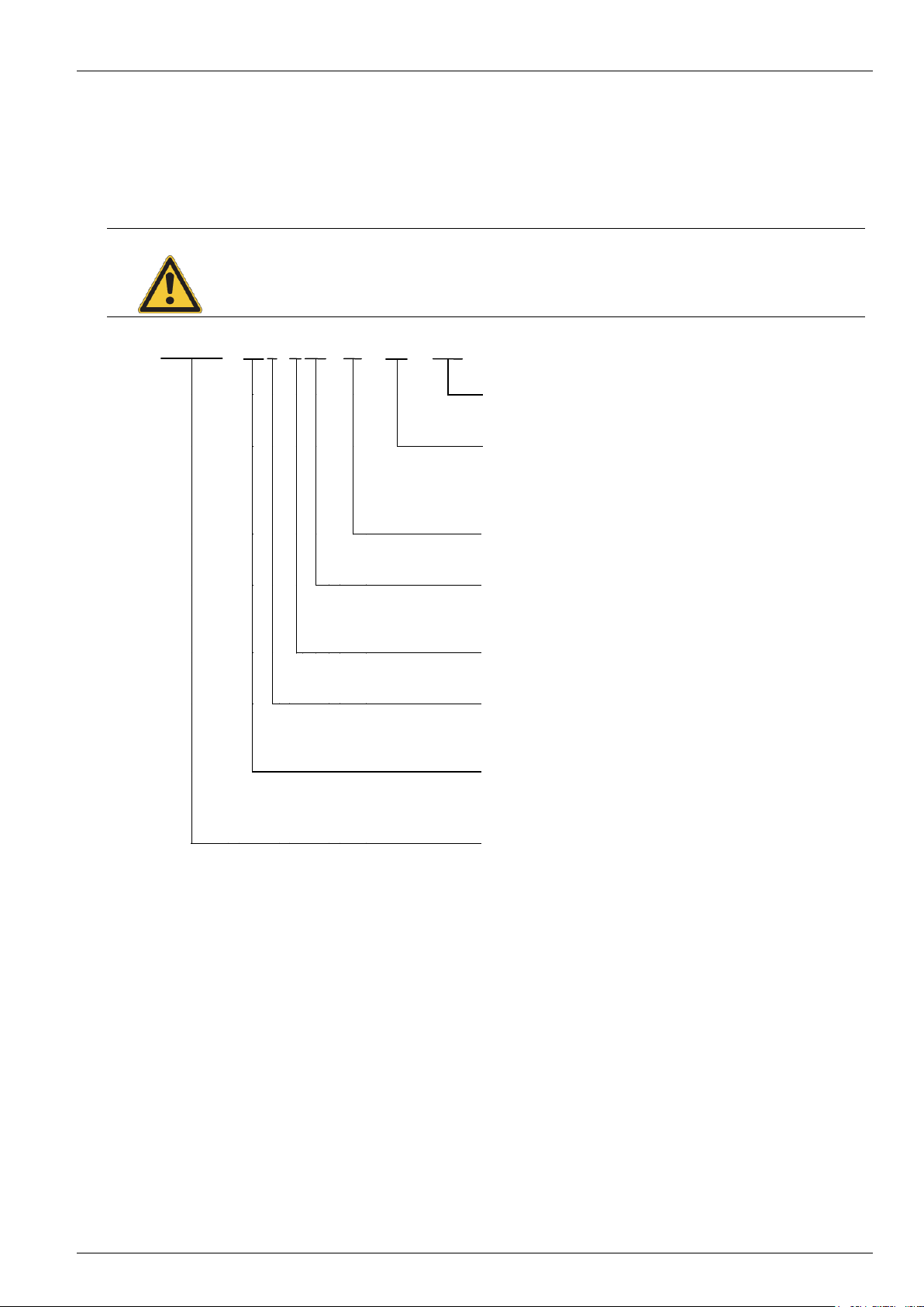
SK 750E
-
55 1 - 3 40 - A - W - ABC
Special device design
(3 letters)
IP protection class of frequency inverter:
space = IP54 version (air cooling)
W = IP65 version (Water cooling)
(incl. lacquered PCB cards)
Integrated noise suppression filter:
A = Class A
Mains voltage:
x23 = 230V
x40 = 400V
Number of mains phases:
3 = 3 phase
Digits before decimal point for power:
1 = 0x.x0
2 = xx.00
Device nominal power (xx):
55 = 5.50kW, …
22 = 22.00kW
Device series:
SK 750E
1.6 Nomenclature / Type code
The NORDAC SK 750E frequency inverter has a nomenclature with the same structure as for other NORDAC
frequency inverters. The information contained therein can be determined in the same way. The type
classification of the frequency inverter contains the device type, the nominal output, data on mains voltage, the
noise suppression filter, protection class and any special device designs.
BU 0750 GB-3311 Subject to technical amendments 11
Page 12
NORDAC SK 750E Manual
Note
The IP65 components and IP66 options (technology units) for the water cooled IP65 version have an
additional "-C" and are modified with the special measures listed below!
Note
With the the IP65 version it must be ensured that the cable lines and cable connections are carefully
matched so that no leaks occur in the SK 750E or any other problems occur that could affect the
maintenance of the IP65 protection class!
1.7 Version with protection class IP54 / IP65
TheNORDAC SK 750E frequency inverter can be ordered in any size and therefore any power stage with the
protection classes IP54 (air cooling) or IP65 (water cooling). These versions can be differentiated by the type
designation. The water cooled version has a "-W" (→ Water cooling) at the end of the type designation.
The protection classes IP54 or IP65 must always be stated when ordering!
The protection classes are determined by the type of cooling. With the air cooled device, the integrated fans
determine the protection class IP54; with the IP65 devices this is determined by the flange to the water cooling.
With the technology units, customer interfaces and special extensions there are no restrictions of functionality
between the IP54 and IP65 versions.
IP54 version:
The protection class IP54 applies for the air cooled SK 750E. Both versions (motor-integrated, close to motor)
are available. The standard modules of the SK 300E (SK TU2-…) and SK 700E (SK CU1-…, SK XU1-…) can
be inserted.
IP65 version:
The water cooled IP65 version has an additional "-W" (→ Water cooling). Both versions (motor-integrated,
close to motor) are also available. In addition, for IP65 devices the technology units (SK TU2-…-C) of the
SK 300E, have an additional "-C" (Coated → lacquered PCBs) in their type designation. As with the IP54
devices, the same standard modules of the SK 700E are inserted as customer interfaces (SK CU1-...) and
special extensions (SK XU1-...).
Special measures:
Coated circuit boards
12 Subject to technical amendments BU 0750 GB-3311
Page 13
2 Assembly and installation
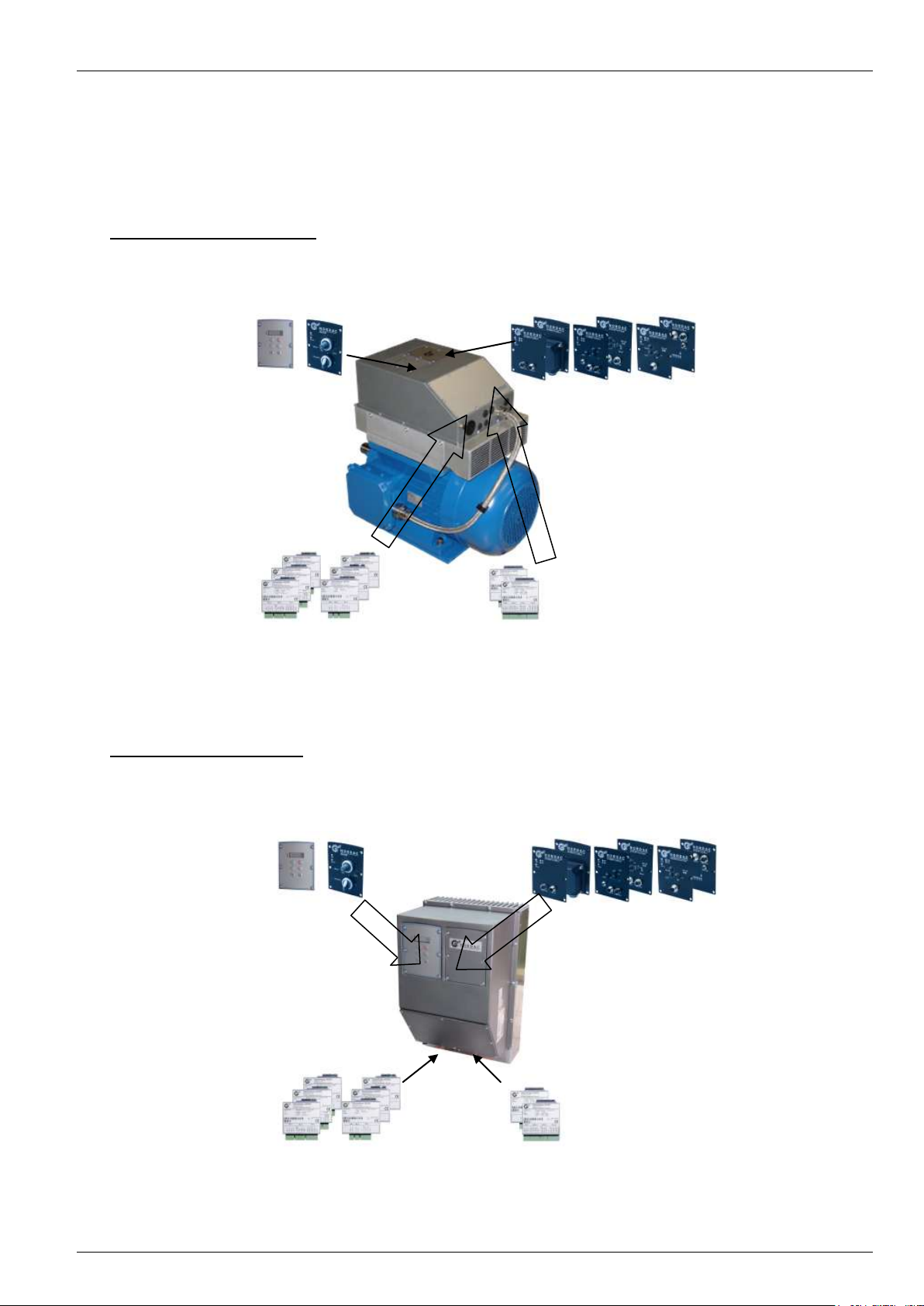
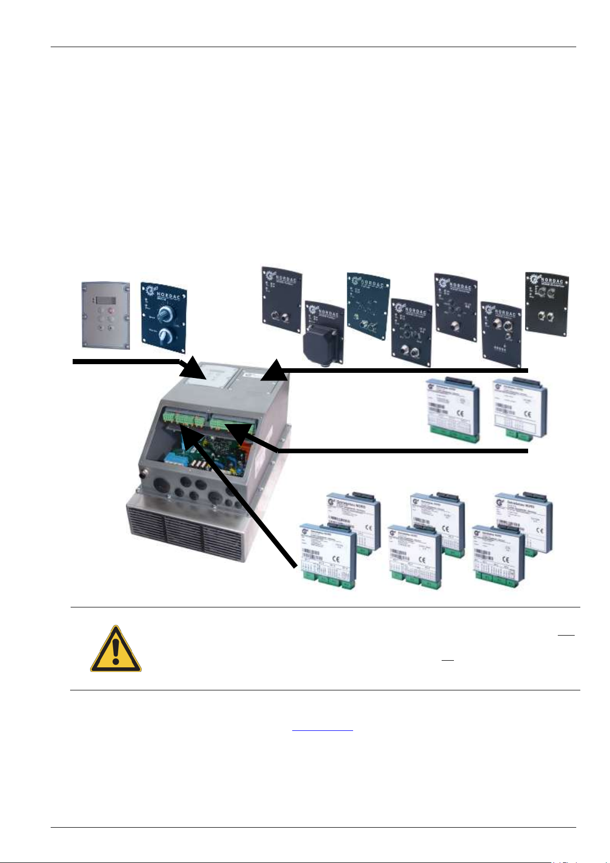
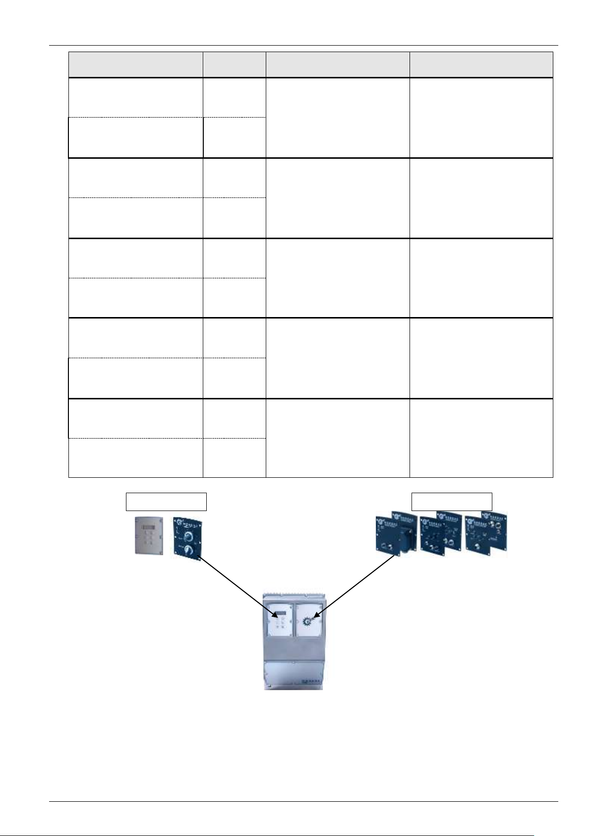
Motor-integrated version:
Fig.: SK 750E in IP54 version (air cooling)
Optional technology unit
SK TU2-CTR
SK TU2-POT
Optional technology unit
Bus modules
Optional customer unit
SK CU1-...
Optional special extension
SK XU1-...
Close-to-motor version:
Optional technology unit
SK TU2-CTR
SK TU2-POT
Optional technology unit
Bus modules
Optional customer unit
SK CU1-...
Optional special extension
SK XU1-...
Fig.: SK 750E in IP54 version (air cooling)
2 Assembly and installation
2.1 Motor-integrated and close to motor layouts
With the motor-integrated version the SK 750E frequency inverter is directly mounted on the motor by means
of an attachment frame and "mounting feet", which integrate it into the drive unit.
With the SK 750E close-to-motor version, the frequency inverter can be mounted close to the motor, i.e. on a
wall or a machine frame for example. A wall-mounting kit is required for this (see Section 2.5).
BU 0750 GB-3311 Subject to technical amendments 13
Page 14
NORDAC SK 750E Manual
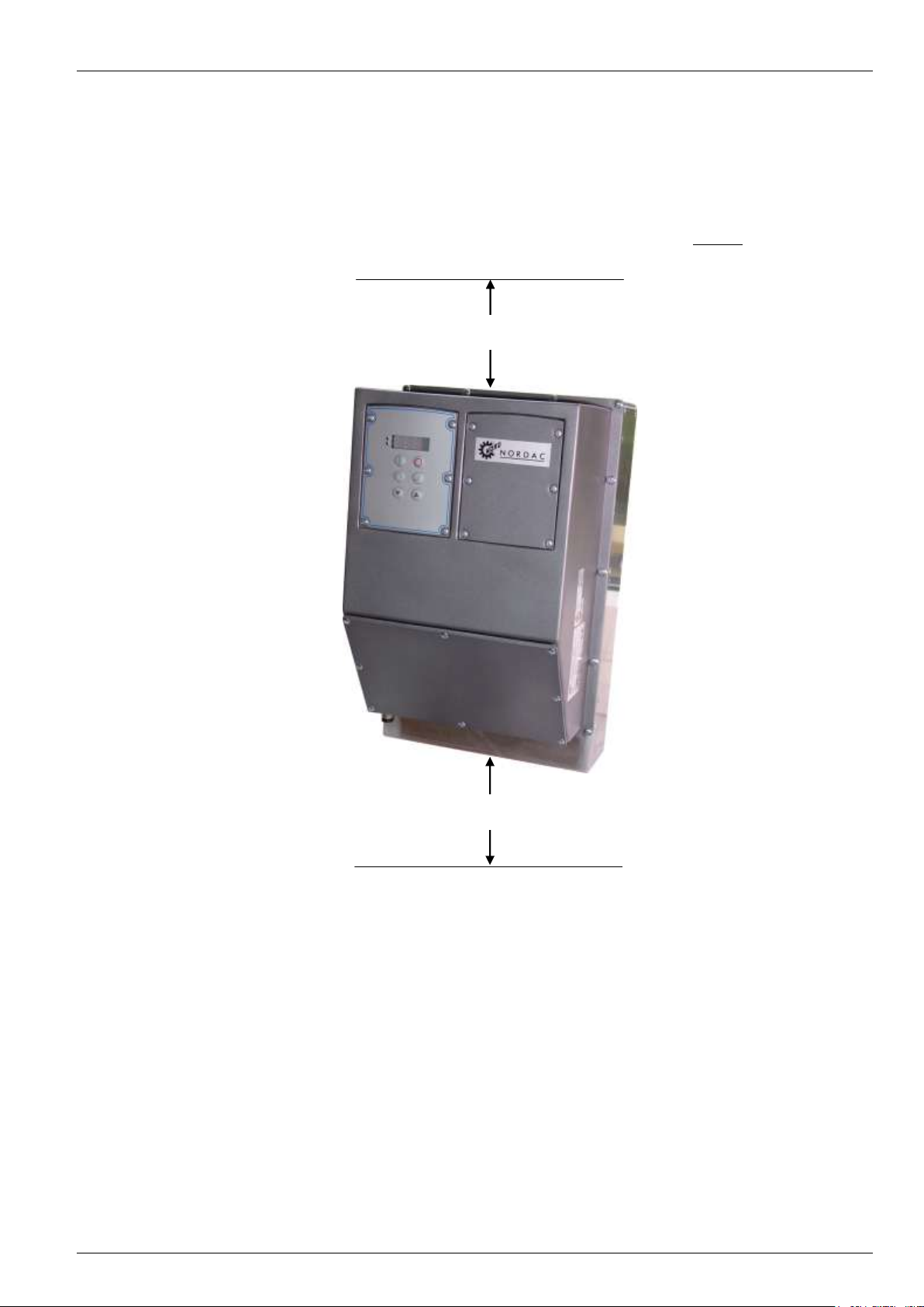
100mm
100mm
2.2 Installation
NORDAC SK 750E frequency inverters are available in various sizes depending on their output. Attention must
be paid to a suitable position when installing.
The equipment requires sufficient ventilation to protect against overheating. For this the minimum guideline
distances from adjacent components above and below the frequency inverter, which could obstruct the air flow
apply. (above > 100 mm, below > 100 mm)
Mounting can be immediately next to each other. The installation position is normally vertical.
If several inverters are arranged above each other, it must be ensured that the upper air entry temperature limit
is not exceeded. (See also Section 9, Technical data). If this is the case, it is recommended that an "obstacle"
(e.g. a cable duct) is mounted between the inverters so that the direct air flow (rising warm air) is impeded.
Warm air must be vented above the device!
14 Subject to technical amendments BU 0750 GB-3311
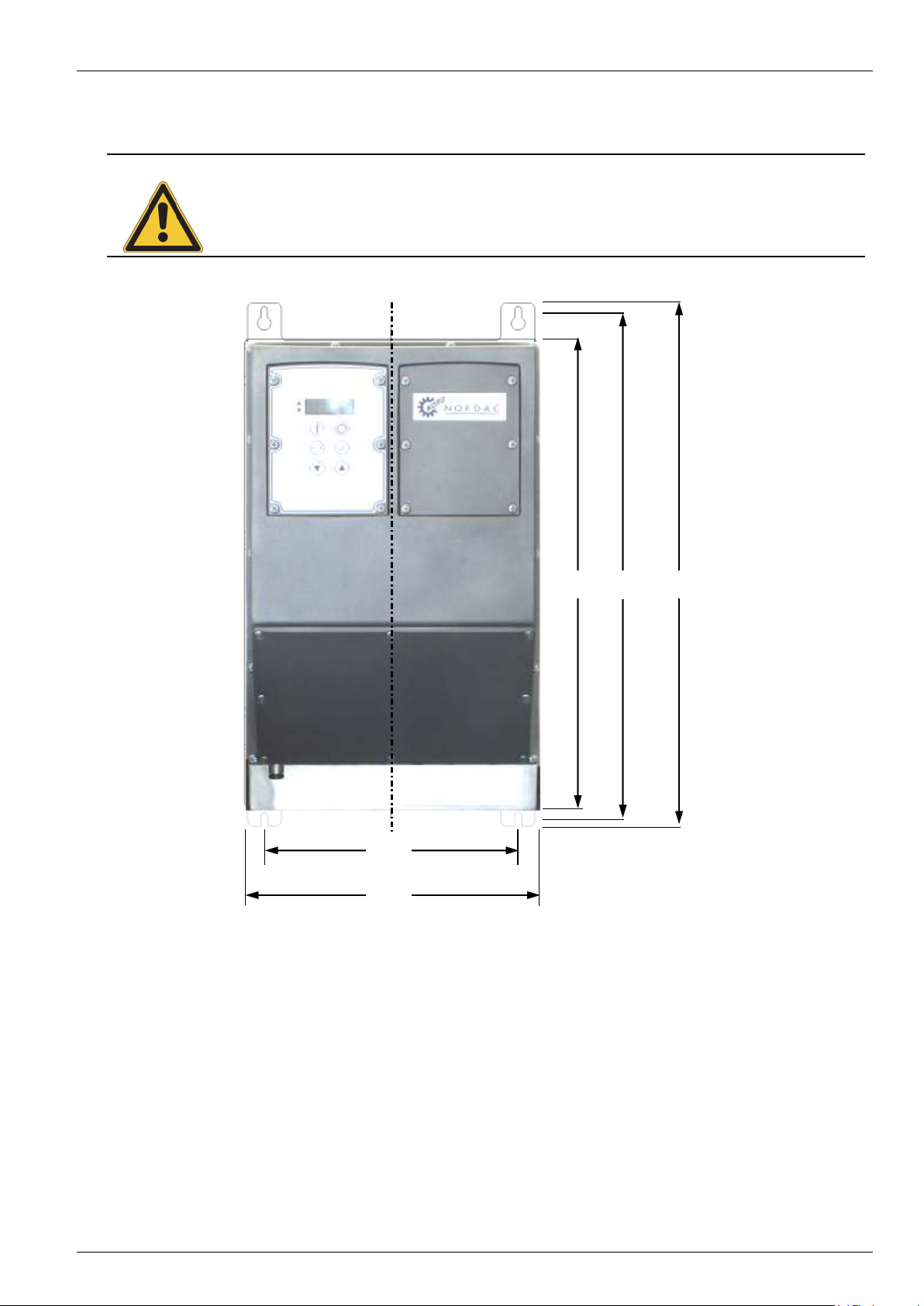
Page 15
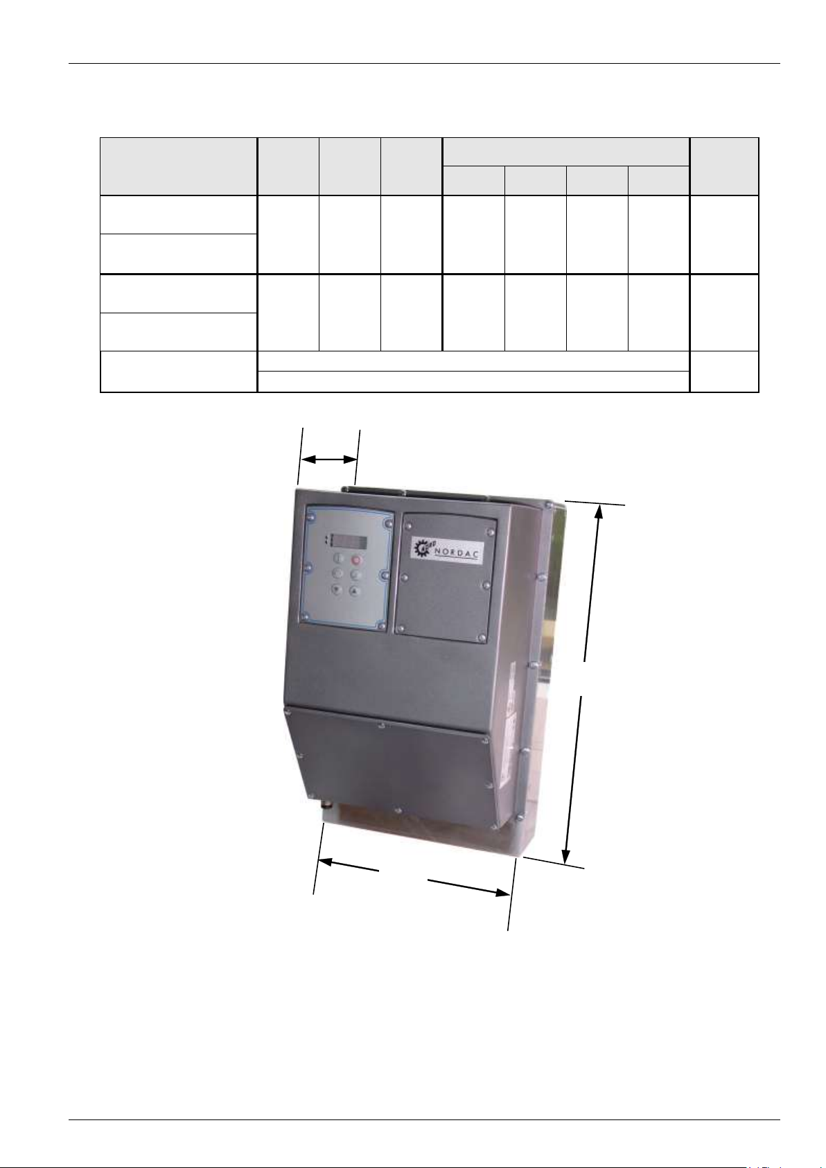
Frequency inverter type
L B D
Wall mounting kit (optional, Section 2.5)
Weight
L1
B1
L2
SK 750E-551-323-A …
SK 750E-751-323-A
414
372 *
255
237.5
165 *
443
401*
220.5
457.5
415.5*
6.5
18.0
SK 750E-551-340-A …
SK 750E-152-340-A
SK 750E-921-323-A …
SK 750E-112-323-A
472
430*
305
253
179 *
501
459*
270.5
516
474*
6.5
23.0
SK 750E-182-340-A …
SK 750E-222-340-A
All dimensions in [mm]
Approx.
[kg]
*) water cooled version
L
B
D
2.3 Dimensions of the SK 750E
2 Assembly and installation
BU 0750 GB-3311 Subject to technical amendments 15
Page 16
NORDAC SK 750E Manual
Type
for device
Part number
SK WMK-750E-Size 1
SK 750E-551-323-A (-W) ... SK 750E-751-323-A (-W)
SK 750E-551-340-A (-W) ... SK 750E-152-340-A (-W)
275219000
SK WMK-750E-Size 2
SK 750E-921-323-A ... SK 750E-112-323-A
SK 750E-182-340-A ... SK 750E-222-340-A
275219010
SK WMK-750E-Size 2-W
(in preparation)
SK 750E-921-323-A -W... SK 750E-112-323-A-W
SK 750E-182-340-A -W... SK 750E-222-340-A-W
275219020
(in preparation)
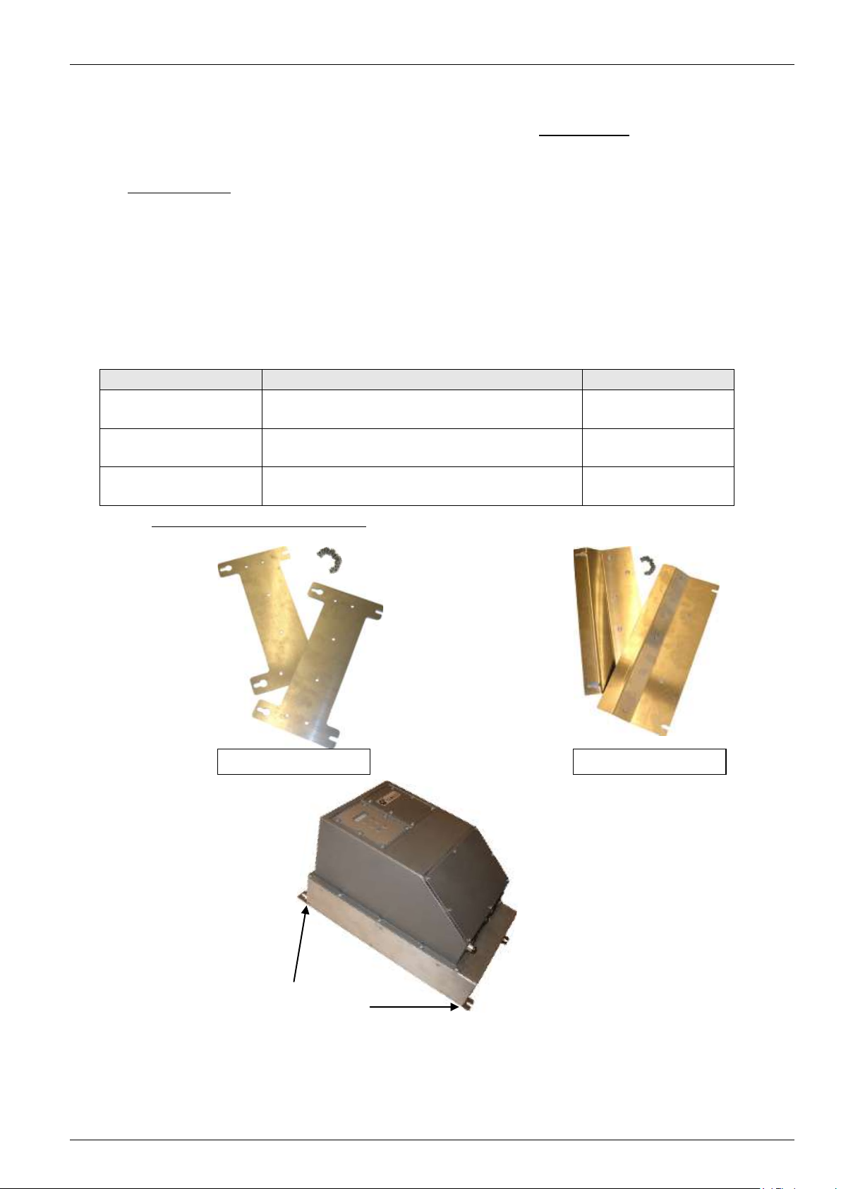
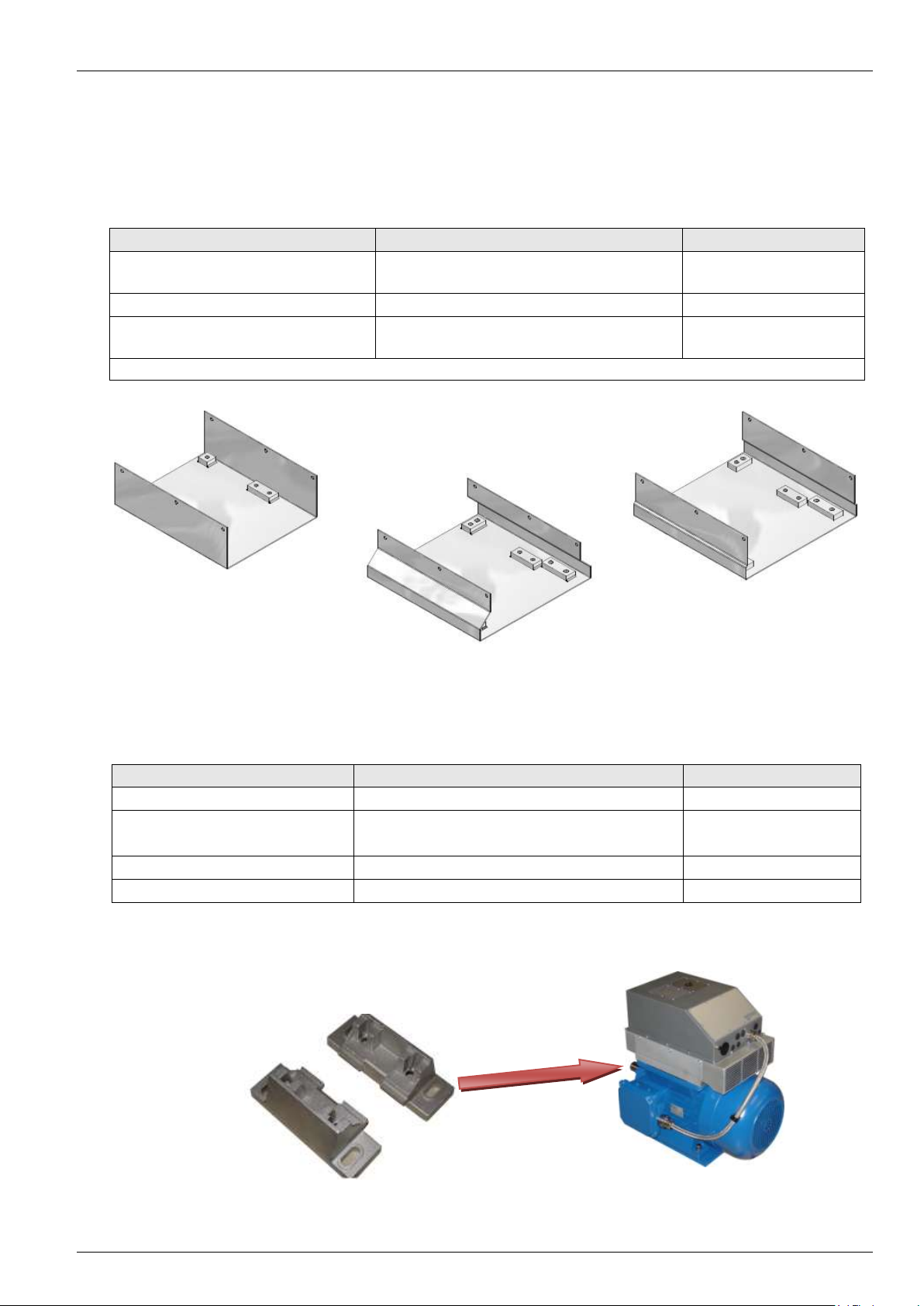
SK WMK-750E-Size 1
SK WMK-750E-Size 2
Components of the wall mounting kits:
Wall mounting kit:
SK WMK-750E-Size 1
2.4 Attachment accessories for the SK 750E
1. Wall mounting, SK WMK-750E Size 1 or. ...Size 2: For the close-to-motor version of the SK 750E
frequency inverter, attachment to a suitable mounting surface is by means of an optional mounting bracket.
2. Motor mounting: Alternatively, there is the possibility of direct mounting on NORD DS standard motors
(motor-integrated version). Additional mounting material is required for this.
2.5 SK 750E wall mounting kit
For use of the SK 750E frequency inverter close to the motor, the wall mounting kit enables the geared motor
and the frequency inverter to be installed separately. For wall mounting of the SK750E, 2 suitable brackets are
required, which can be ordered as accessories. These are screwed to the rear of the SK 750E with the
fastening material provided. Both of the wall mounting kits comply with protection classes IP54 or IP65. The
same wall mounting kit is required for Size 1 air cooled and water cooled versions. For Size 2, there are
differences in the wall mounting kits for the two versions.
16 Subject to technical amendments BU 0750 GB-3311
Page 17
Note
Please refer to the table in Section 2.2 for the dimensions.
B1
B
L
L2
L1
Fig.: SK 750E with SK WMK-750E-Size 1
2.5.1 Dimensions of the SK 750E with wall mounting kit
2 Assembly and installation
BU 0750 GB-3311 Subject to technical amendments 17
Page 18
NORDAC SK 750E Manual
Attachment frame
for device
Part number
Attachment frame 750E-Size 1-IEC132
SK 750E-551-323-A ... SK 750E-751-323-A
SK 750E-551-340-A ... SK 750E-751-340-A
275218000
Attachment frame 750E-Size 1-IEC160*
SK 750E-112-340-A ... SK 750E-152-340-A
275217000
Attachment frame 750E-Size 2-IEC160*
SK 750E-921-323-A ... SK 750E-112-323-A
SK 750E-182-340-A ... SK 750E-222-340-A
275216000
*Also suitable for motor size IEC132
Attachment frame 750E-Size 1-IEC132
Attachment frame 750E-Size 1-IEC160
Attachment frame 750E-Size 2-IEC160
Part number
Motor size
Number per drive unit
16630900
132
2
17481000 ("Foot")
160, 180MX, 180LX (Siemens)
2
17181010 (Screw set)
4
17430900
160 L, 160 LH, 160 MH, 180MX, 180LX (NORD)
2
17130900
160M (NORD)
2
2.6 Mounting of the SK750E directly on a motor
For motor-mounted (motor-integrated) use of the SK 750E frequency inverter direct installation of the geared
motor and the frequency inverter is possible using the attachment frame and the additional "motor mounting
feet". Three different attachment frames are available for mounting on the various sizes of motor (132, 160,
180MX/LX).
The number and version of the attachment feet to be used depends on the type of motor and can be obtained
from the following table.
Example: "Attachment feet" for size 132 motor, Part No. 16630900:
18 Subject to technical amendments BU 0750 GB-3311
Page 19

2 Assembly and installation
NOTE
The control cables, line cables and motor cables must be laid separately. Under no circumstances
may they be laid in the same protective conduit or cable duct.
The test equipment for high voltage insulation must not be used for cable which are connected to
the frequency inverter.
2.7 Wiring guidelines
The frequency inverter has been developed for use in an industrial environment. In this environment, high
levels of electromagnetic interference can influence the frequency inverter. In general, correct installation
ensures safe and problem-free operation. To meet the limiting values of the EMC directives, the following
instructions should be complied with.
1) Ensure that all equipment in the control cabinet or field is securely earthed using short earthing cables
which have large cross-sections and are connected to a common earthing point or earthing rail. It is
especially important that every control device connected to the frequency inverters (e.g. an
automation device) is connected, using a short cable with large cross-section, to the same earthing
point as the inverter itself. Flat conductors (e.g. metal clamps are preferable, as they have a lower
impedance at high frequencies.
2) The PE lead of the motor controlled by the frequency inverter must be connected as directly as
possible to the earth connection of the cooling element, together with the PE of the corresponding
frequency inverter mains supply. The presence of a central earthing bar in the control cabinet and the
grouping together of all bonding conductors to this bar normally ensures safe operation. (See also
Chapter 8.3/8.4 EMC guidelines)
3) Where possible, shielded cables should be used for control circuits. The shielding at the cable end
should be carefully sealed and it must be ensured that the wires are not laid over longer distances
without shielding.
The shields of analog setpoint cables should only be earthed on one side on the frequency inverter.
4) The control cables should be installed as far as possible from power cables, using separate cable
ducts, etc. Where cables cross, an angle of 90° should be ensured as far as possible.
5) Ensure that the contactors in the cabinet are interference protected, either by RC circuits in the case
of AC contactors or by free-wheeling diodes for DC contactors, for which interference suppressors
must be connected to the contactor coils. Varistors for over-voltage limitation are also effective.
This interference suppression is particularly important when the contactors are controlled by the relay
in the frequency inverter.
6) Shielded or protected cables should be used for load connections (motor cable) and the
shielding/protection should be earthed at both ends, if possible directly to the frequency inverter
PE/EMC terminal.
In addition, EMC-compliant wiring must be ensured. (see also Section 8.3/8.4 EMC). If required, an
optional integrated motor filter is available.
7) Select the lowest possible switching frequency. This will reduce the intensity of the electromagnetic
interference produced by the frequency inverter.
The safety regulations must be complied with under all circumstances when
installing the frequency inverter!
BU 0750 GB-3311 Subject to technical amendments 19
Page 20
NORDAC SK 750E Manual
WARNING
NOTE
THESE DEVICES MUST BE EARTHED.
Safe operation of the devices requires that is installed and commissioned by qualified
personnel in compliance with the instructions provided in this Manual.
In particular, the general and regional installation and safety regulations for work on
high voltage systems (e.g. VDE) must be complied with as must the regulations
concerning correct use of tools and the use of personal protection equipment.
Dangerous voltages can be present at the motor connection terminals even when the
inverter is switched off. Always use insulated screwdrivers on these terminal fields.
Ensure that the input voltage source is not live before setting up or changing
connections to the unit.
Make sure that the inverter and motor have the correct supply voltage set.
Switching of the motor or brake resistor cable in not permitted when they are
connected to a voltage.
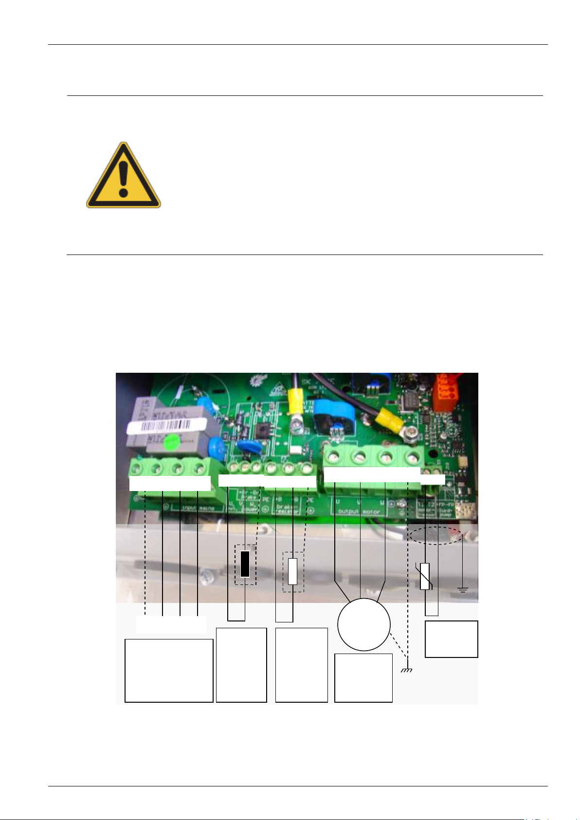
PE
L1
L2
L3
PE L1 L2 L3
+B -B PE
U V W PE
T1 T2
M
3 ~
Mains connection
a) 3 ~ 220-240V ~
b) 3 ~ 380-440V ~
c) 3 ~ 460/480V ~
Brake resistor
connection
R = 10-40Ω
for further
details see
Section
9.2/9.3
3~ motor
connection
Star/Delta
Temperature
sensor
(PTC)
+Br -Br PE
Electro-
magnetic
brake coil
a) 105V =
b) 180V =
c) 205V =
2.8 Electrical Connection
2.9 Electrical connection of power unit
The line, motor, brake resistor and control connections are located on the underside of the device. To gain
access to the terminals, the device covers (cover and terminal cover) must be removed. The connection
terminals are now accessible from the front or from above. The cables must be fed into the frequency inverter
via suitable screw fittings and pretected from tension. All covers must be put back in place before switching on
the supply voltage!
20 Subject to technical amendments BU 0750 GB-3311
Page 21
2 Assembly and installation
ATTENTION
Proper earthing must be ensured for
all metal covers. Otherwise the
frequency inverter must not be put
into operation (see illustration).
NOTE
If using certain wire end sleeves are used, the maximum cross-section which can be connected can
be reduced.
NOTE
If synchronous machines are connected or several motors are connected in parallel, the
frequency inverter must be operated with linear voltage/frequency characteristic curves,
P211 = 0 and P212 = 0.
Before connecting the device, the following must be observed:
1. Ensure that the voltage source provides the correct voltage and is suitable for the current required (see
Section 9 Technical data). In addition, care must be taken that suitable power switch with the specified
rated current range is installed between the voltage source and the frequency inverter.
2. Connect the mains voltage directly to the mains terminals L1 - L2 - L3 and connect the earth (PE).
3. A four-core cable must be used to connect the motor. The cable must be connected to the motor terminals
U - V - W and the PE.
4. If shielded motor cables are used (recommended), the cable shielding must also be connected to a large
area of the metal screw fittings.
Note: The use of shielded cables is essential in order to maintain the specified radio interference
suppression level. (See also Section 10.5 EMC limit value classes)
Usually, the line, motor and brake resistor cables are
connected first as their terminals are located on the
bottom circuit board. The various metric screw
fittings on the underside of the device are used as
cable glands (see 2.9.7 Cable Glands)
BU 0750 GB-3311 Subject to technical amendments 21
Page 22
NORDAC SK 750E Manual
Mains input voltage (AC)
Brake coil voltage (DC)
400V ~
180V =
460V ~ ... 480V ~
205V =
230V ~
105V =
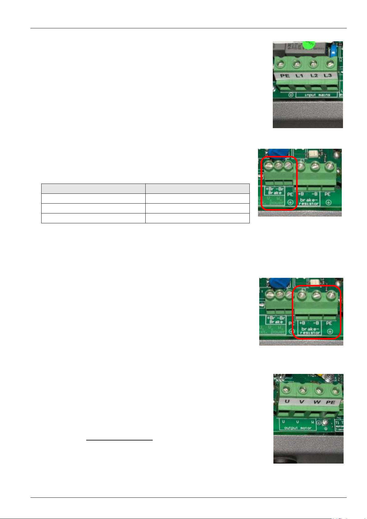
2.9.1 Mains supply (PE, L1, L2, L3)
No special safety devices are required on the mains input side for the frequency
inverter, the use of the normal mains protection (see 9 Technical Data) and a
master switch or contactor is recommended.
Note: Use of this frequency inverter on an IT network is possible after minor
modifications. Please consult your supplier.
2.9.2 Electromagnetic brake (+Br, -Br, PE)
An output voltage is generated by the frequency inverter at the terminals
-Br/+Br to actuate an electromechanical motor brake (see Section 2.9,
Electrical connections to the power unit).
This depends on the supply voltage present in the frequency inverter. The
assignment is as follows:
Note: The allocation of the correct brake or brake coil voltage must be
taken into account in the design with reference to the mains
voltage of the frequency inverter.
2.9.3 Brake resistor (+B, -B, PE)
During dynamic braking (frequency reduction) of a three-phase motor,
electrical energy is returned to the inverter. In order to avoid overcurrent
switch-off of the frequency inverter, the integrated brake chopper can convert
the returned energy into heat by connection of an external braking resistor.
The connection for the frequency inverter → brake resistor should be
shielded and as short as possible.
Switching of this connection must only be made when no voltage is present!
Note: The possible generation of large amounts of heat in the braking
resistor must be taken into account.
2.9.4 Motor cable (U, V, W, PE)
The motor cable maximum length of 150m (Please note also Section 10.5 EMC
limit value classes). If a shielded motor cable is used, or the metallic cable duct is
well earthed, the maximum length of 50m should not be exceeded. For longer
cable lengths, the frequency inverter can be equipped with an optional internal
motor filter (at extra charge).
Switching (contactor or motor protection switch) at the output (U, V, W), is not
permitted while the frequency inverter is delivering current!
Note: For multiple motor operation the total cable length consists of the sum
of the individual cable lengths. If the sum of the cable lengths is too
large, an optional internal motor filter should also be ordered.
22 Subject to technical amendments BU 0750 GB-3311
Page 23
2 Assembly and installation
NOTE
The cable routing of the control cables or temperature sensor should always be separate from the
motor cable and be made with shielded cables.
Internal switching in the inverter prevents excessive voltage to the thermistor. Further details can be
found in Section 8, Error messages.
Size 1:
SK 750E-551-323-A ... SK 750E-751-323-A (5.5 / 7.5kW, 230V)
SK 750E-551-340-A ... SK 750E-152-340-A (5.5 … 15kW, 400V)
Terminal block
Mains input
Mech. Brake
Brake resistor
Motor output
Temp. Sensor
VDE rigid
0.5 - 16mm²
0.2 - 6mm2
0.2 - 6mm²
0.5 - 16mm²
0.14 - 2.5mm²
VDE flexible
0.5 - 10mm²
0.2 - 4mm2
0.2 - 4mm²
0.5 - 10mm²
0.14 - 2.5mm²
UL/cUL
AWG 20-6
AWG 24-10
AWG 24-10
AWG 20-6
AWG 26-14
Size 2:
SK 750E-921-323-A ... SK 750E-112-323-A (9.2 / 11kW, 230V)
SK 750E-182-340-A ... SK 750E-222-340-A (18.5 / 22kW, 400V)
Terminal block
Mains input
Mech. Brake
Brake resistor
Motor output
Temp. Sensor
VDE rigid
0.5 - 35mm²
0.2 - 6mm2
0.5 - 16mm²
0.5 - 35mm²
0.14 - 2.5mm²
VDE flexible
0.5 - 25mm²
0.2 - 4mm2
0.5 - 10mm²
0.5 - 25mm²
0.14 - 2.5mm²
UL/cUL
AWG 20-2
AWG 24-10
AWG 20-6
AWG 20-2
AWG 26-14
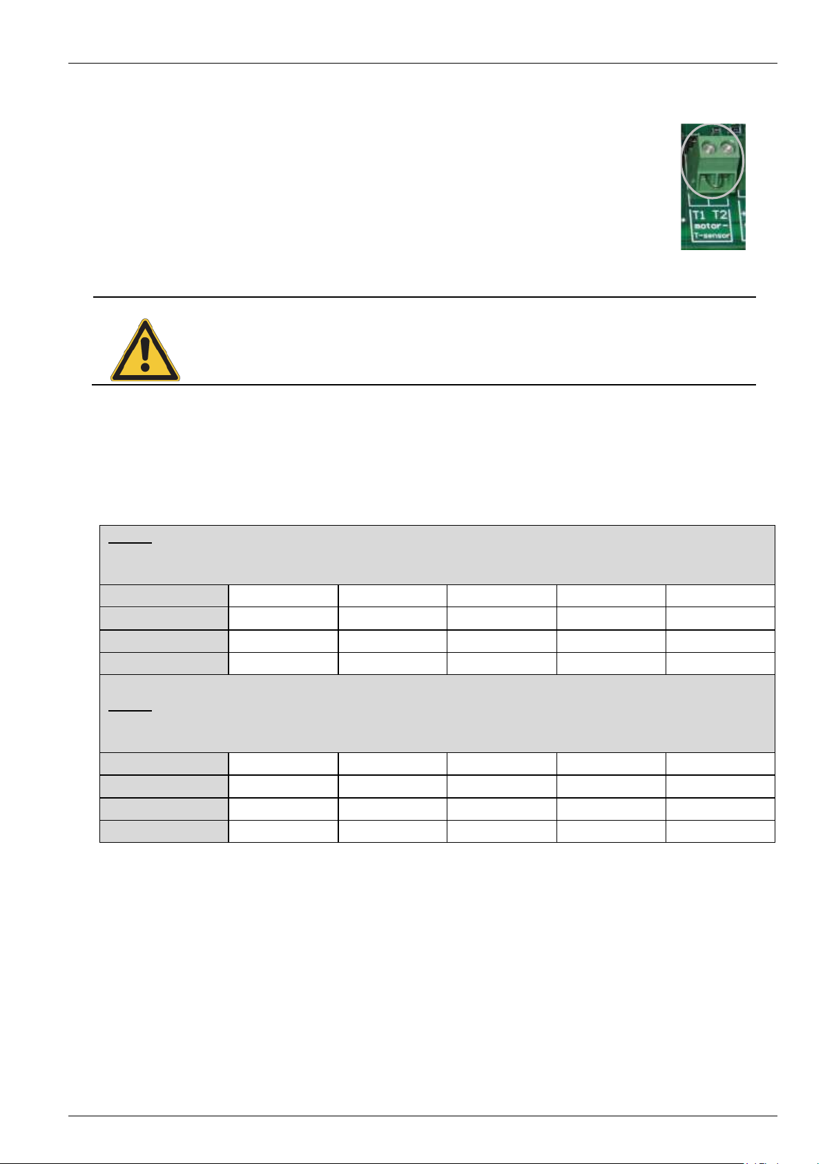
2.9.5 Temperature sensor (T1, T2)
This input can be used to evaluate a temperature sensor (thermistor or temperaturecontrolled switch) in order to prevent overheating.
If the thermistor has a high resistance or the temperature controlled switch opens, the
frequency inverter switches off and reports a motor overtemperature error (E001).
If no temperature sensor is used, terminals T1 and T2 must be bridged.
An error message can be acknowledged by switching the mains off and on again, or by
pressing the ENTER key on a control display (ControlBox or ParameterBox).
Evaluation of a temperature sensor is also possible by means of the optional customer units (SK CU1-...).
Further details can be found in Section 3.3, Overview of customer units.
2.9.6 PowerConnection Terminals
BU 0750 GB-3311 Subject to technical amendments 23
Page 24

NORDAC SK 750E Manual
NOTE
All control voltages refer to a common reference potential 0V / GND.
If necessary, 5 / 15V can be taken from several terminals. The sum the currents must not exceed
300mA.
2.9.7 Control connections (optional)
The manner and type of control unit connections are dependent on the options chosen (customer unit / special
extension unit). The possible variants are described in Section 3.3/3.4.
Here you will find general data and information on all customer units and special extension units.
Connection terminals: - Plug-in clip connectors can be released with a small screwdriver
Maximum
connection cross-section: - 1.5mm2 or 1.0mm2 (AWG 26-14 or 26-16), according to option
Cable: - laid separately from the mains/motor cables and shielded
Control voltages: - 5V, max. 300mA, for the supply of a ParameterBox SK PAR-2H
(Short-circuit proof) - 10V, max. 10mA, reference voltage for an external potentiometer
- 15V, max. 300mA, for the supply of digital inputs or an incremental or
absolute encoder
- analog output 0 - 10V, max. 5mA for an external display unit
24 Subject to technical amendments BU 0750 GB-3311
Page 25

2 Assembly and installation
Line input
Brake resistor
Motor output
RS485 interface
→ SK PAR-2H connection
Temperature sensor
Control level
Fig.: Air cooled SK 750E, Size 1
Mech. Brake
Size
Line input
Motor output
Control level
Brake resistor
Temperature
sensor
Size 1
M32
M25
3x M25
2x M16
2x M12
Size 2
M40
M32
3x M25
2x M16
2x M12
NOTE
For operation with an SK 750E, the motor should be equipped with a temperature sensor.
2.9.8 Cable connections
With the cable connections, a differentiation must be made between Size 1 and Size 2 of the SK 750E
frequency inverter. Both have different cable connections for the line input and the output from the frequency
inverter to the motor (see the table below). The cable connections for the control level, control of the brake
resistor and the temperature sensor input are the same for both sizes.
Available cable connections for Size 1 and 2:
BU 0750 GB-3311 Subject to technical amendments 25
Page 26
NORDAC SK 750E Manual
WARNING
Modules must not be inserted or removed unless the device is free of voltage. The slots must only
be used for the intended modules.
Installation of a technology unit separate from the frequency inverter is not possible. It must be connected
directly to the frequency inverter.
NOTE
3 Options
3.1 Modular options
By combining various modules for display, control and parameterisation, the NORDAC SK 750E can be easily
adapted to various requirements.
Modules are available for processing analog and digital signals and for all common Bus systems.
Alphanumerical display and operating modules can be used for simple commissioning. For more complex
tasks, various connections to a PC or an automation system can be selected.
Technology units (Technology Unit, SK TU2-...) are located on the frequency inverter and are accessible
from the outside for manual control or parameterisation, or to provide connection to field bus systems.
Customer interfaces (Customer Unit, SK CU1-...) are installed inside the frequency inverter. These allow
control with analog and digital signals or connection to the bus systems.
Special extension units (Extension Unit, SK XU1-...) include special functions such as speed control with
incremental encoders or position control with incremental or absolute encoders.
Further detailed information can be found in the Options manuals.
- www.nord.com –
26 Subject to technical amendments BU 0750 GB-3311
Page 27
3.2 Overview of Technology Units
ATTENTION
Left / right TU slot
When inserting the technology units, the left and right slots must be considered separately. The
left hand slot must only be used for the ControlBox or PotentiometerBox control unit. The right
hand slot can be used for all modules. Combined operation of the PotentiometerBox and the
ControlBox is not possible!
ATTENTION
The technology units SK TU2-… are available for protection class IP55 and technology units
SK TU2-…-C for IP66. It must be noted that the functionality and dimensions of the technology
units are identical for the IP55 and IP66 versions. However, with the IP66 version special
measures, such as coated PCBs are used in order to comply with the protection class.
Technology unit
SK TU2-...
Protection
class
Description
Data
ControlBox
SK TU2-CTR
Part. No. 275130130
IP55
Used for commissioning,
parameterisation, configuration
and control of the frequency
inverter.
4-digit, 7-segment LED display,
keyboard
ControlBox
SK TU2-CTR-C
Part. No. 275170130
IP66
PotentiometerBox
SK TU2-POT
Part. No. 275130060
IP55
For direct control of the
frequency inverter without
additional installation or setting
1 potentiometer 0...100 %
1 switch left-0-right
PotentiometerBox
SK TU2-POT-C
Part. No. 275170060
IP66
Profibus module (standard)
SK TU2-PBR
Part. No. 275130070
IP55
This interface enables control of
the NORDAC SK 750E via the
Profibus DP serial port.
Profibus interface
Baud rate: 1.5 MBit/s
2x 5 pin M12 system connectors
Profibus module (standard)
SK TU2-PBR-C
Part. No. 275170070
IP66
Profibus module (terminals)
SK TU2-PBR-KL
Part. No. 275130065
IP55
This interface enables control of
the NORDAC SK 750E via the
Profibus DP serial port.
Profibus interface
Baud rate: 1.5 MBit/s
8 pin terminal
Profibus module (terminals)
SK TU2-PBR-KL-C
Part. No. 275170065
IP66
3.2 Overview of Technology Units
Technology units are optional modules and are plugged onto the top of the frequency inverter. They are for the
control or parameterisation of the inverter and for the display of the actual operating values. The
PotentiometerBox and the ControlBox are available as technology units for simple control of the frequency
inverter and various bus modules are available for connection to a higher level control unit.
A differentiation is made between IP55 and IP66 technology units. Technology units with protection class
IP555 are used for the air cooled SK 750E and protection class IP66 is used for the water cooled SK 750E.
BU 0750 GB-3311 Subject to technical amendments 27
Page 28
NORDAC SK 750E Manual
Technology unit
SK TU2-...
Protection
class
Description
Data
Profibus module (ext. 24V)
SK TU2-PBR-24V
Part. No. 275130110
IP55
This interface enables control of
the NORDAC SK 750E via the
Profibus DP serial port.
Profibus interface
Baud rate: 12 MBit/s
2x 5 pin M12 system connectors
1 external 24 V power supply
Profibus module (ext. 24V)
SK TU2-PBR-24V-C
Part. No. 275170110
IP66
InterBus module
SK TU2-IBS
Part. No. 275130080
IP55
This interface enables control of
the NORDAC SK 750E via the
serial InterBus port.
InterBus interface
Baud rate: 500 KBit/s
2x 5 pin M12 system connectors
InterBus module
SK TU2-IBS-C
Part. No. 275170080
IP66
DeviceNet module
SK TU2-DEV
Part. No. 275130090
IP55
This option enables control of
the NORDAC SK 700E via the
DeviceNet serial port using the
DeviceNet protocol.
DeviceNet interface
Baud rate: 500 KBit/s
1x 5 pin M12 system connector
DeviceNet module
SK TU2-DEV-C
Part. No. 275170090
IP66
CANopen module
SK TU2-CAO
Part. No. 275130100
IP55
This option enables control of
the NORDAC SK 750E via the
CANbus serial port using the
CANopen protocol.
CANopen interface
Baud rate: up to 1 MBit/s
2x 5 pin M12 system connectors
CANopen module
SK TU2-CAO-C
Part. No. 275170100
IP66
AS interface module
SK TU2-AS1
Part. No. 275130120
IP55
This interface enables the
control of sensors and
actuators. In addition, the NORD
SK 750E can be parameterised
via the AS interface
AS interface
2 x 2 M12 5 pin sockets /
connectors
AS interface module
SK TU2-AS1-C
Part. No. 275170120
IP66
Control units
Bus modules
28 Subject to technical amendments BU 0750 GB-3311
Page 29
WARNING
Modules must not be inserted or removed unless the device is free of voltage. The slots must only
be used for the intended modules.
Installation of a technology unit separate from the frequency inverter is not possible. It must be connected
directly to the frequency inverter.
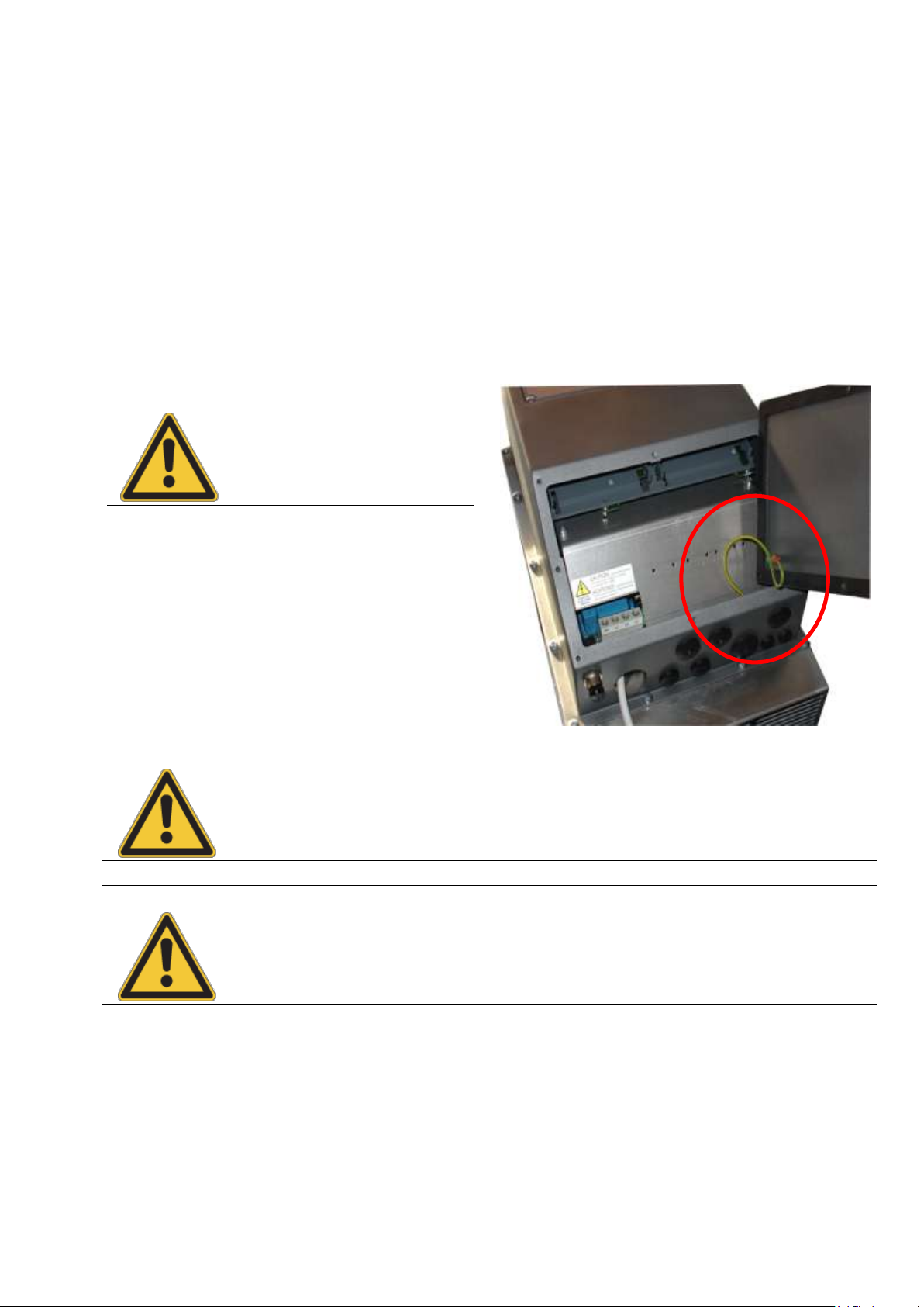
NOTE
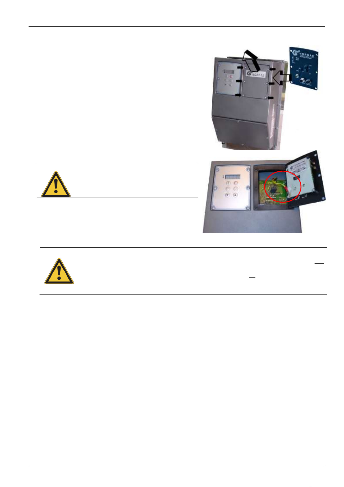
ATTENTION
Operation is not permitted if there is no secure
PE connection to the frequency inverter and to
the technology unit (see adjacent illustration)!
3.2.1 Installing the Technology Unit
Installation of the technology units must be carried out as
follows:
1. Switch off the mains voltage, observe the waiting
period.
2. Remove the blank cover by removing the 6 screws
and the PE cable.
3. Connect the technology unit to the PE cable and
push it in using slight pressure. Take care that the
connector strip makes proper contact.
4. Tighten the 6 fastening screws.
3.2 Overview of Technology Units
BU 0750 GB-3311 Subject to technical amendments 29
Page 30
NORDAC SK 750E Manual
NOTE
The digital frequency setpoint is factory set to 0Hz. To check whether the drive is working, a
frequency setpoint must be entered with the key or a jog frequency must be entered via the
relevant parameter >Jog frequency< (P113).
Settings should only be implemented by qualified personnel, strictly in accordance with the
warning and safety information.
ATTENTION:The drive may start immediately after pressing the START key !
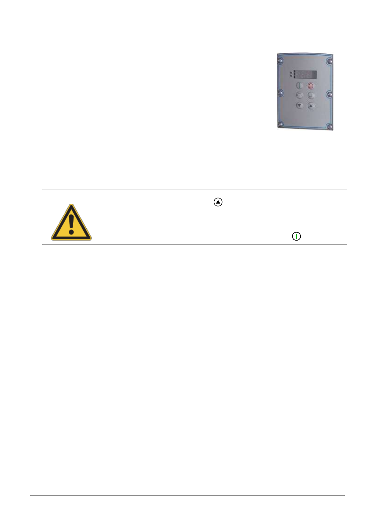
3.2.2 ControlBox SK TU2-CTR
(SK TU2-CTR, Part No.: 275130130)
(SK TU2-CTR-C, Part No.: 275170130)
This option is used as a simple parameterisation, display and control tool for the
frequency inverter SK 750E.
Features:
4-digit, 7-segment LED display
Direct control of a frequency inverter
Display of the active parameter set and operating values
After mounting the ControlBox and switching on the mains supply, horizontal dashes are displayed in the
4-digit, 7 segment display. This display signals the operational readiness of the frequency inverter.
If a jog frequency is preset in parameter P113, the display alternates between 0.0Hz and the value in P113.
If the frequency inverter is enabled, the display changes automatically to the operating value selected in
parameter >Selection Display value< P001(factory setting = actual frequency).
The actual parameter set is shown by the 2 LEDs next to the display on the left in binary code.
30 Subject to technical amendments BU 0750 GB-3311
Page 31

To switch on the frequency inverter. The frequency inverter is now enabled with the set jog frequency
(P113). A preset minimum frequency (P104) may at least be provided.
Parameter >Interface< P509 must = 0.
To switch off the frequency inverter. The output frequency is reduced to the absolute minimum
frequency (P505) and the frequency inverter shuts down.
7-segment
LED
display
Shows the actual operating value set during operation (selection in P001) or an error code. During
parameterisation, the parameter numbers or the parameter values are shown. When switched off, but in
standby mode, four dashes "_ _ _ _" are displayed.
LEDs
1
2
The LEDs indicate the actual operating parameter set in the display and the actual parameter set being
parameterised during parameterisation. In this case the display is coded in binary form.
1
2
= P1
2
1
= P2
1
2
= P3
2
1
= P4
The direction of rotation of the motor changes when this key is pressed. "Rotation to the left" is indicated
by a minus sign. Attention! Take care when operating pumps. screw conveyors, fans, etc. Block the
key with parameter P540.
Press key to increase the frequency. During parameterisation, the parameter number or parameter
value is increased
Press the key to reduce the frequency. During parameterisation, the parameter number or parameter
value is reduced.
Press "ENTER" to store a changed parameter value, or to switch between parameter number or
parameter value.
NOTE: If a changed value is not to be stored, the key can be used to exit from the parameter
without saving the change.
ControlBox functions:
3.2 Overview of Technology Units
BU 0750 GB-3311 Subject to technical amendments 31
Page 32

NORDAC SK 750E Manual
STOP
Store actual frequency as
jog frequency
(Enter key)
Set frequency = 0Hz
(press simultaneously)
Increase frequency
Change rotation direction
(Direction key)
Decrease frequency
START
Parameter set display
Emergency stop
(press simultaneously)
Controlling the frequency inverter with the ControlBox
The frequency inverter can only be controlled via the ControlBox, if it has not previously been enabled via the
control terminals or via a serial interface (P509 = 0).
If the START key is pressed, the frequency inverter switches to the operating display (selection P001). The
frequency inverter delivers 0Hz or a higher set minimum frequency (P104) or jog frequency (P113).
Parameter set display:
The LEDs indicate in the display the actual operating parameter set and during parameterisation ( P000) the
actual parameter set to be parameterised. In this case, the display appears in binary form.
The parameter set can also be changed during operation via the parameter P100 (control via ControlBox).
Frequency setpoint:
The actual frequency setpoint depends on the setting in the parameters jog frequency (P113) and minimum
frequency (P104). This value can be altered during keyboard operation with the value keys and
permanently stored as the jog frequency in P113 by pressing the ENTER key.
Emergency stop:
By simultaneously pressing the STOP key and the "Change direction key” , an emergency stop can be
initiated.
32 Subject to technical amendments BU 0750 GB-3311
Page 33

3.2 Overview of Technology Units
Simultaneous actuation:
Switching from control to
parameterisation while the
drive is running
(See Item 3)
Select menu group,
display parameter value
(Enter key)
One level each time back to
the operating value display
Next menu group or
parameter number
Previous menu group or
parameter number
Switching from
parameterisation to
control
(See Item 3)
Parameter set display
Parameterisation with the ControlBox
Parameterisation of the of the frequency inverter can be performed in the various operating states. All
parameters can always be changed online. Switching to the parameter mode is carried out in different ways
depending upon the operating states and the enabling source.
1. If there is noenable (if necessary press the STOP key ) via the ControlBox, the control terminals or
a serial interface, it is still possible to switch to parameterisation mode from the operating value display
by means of the value keys or . P 0 _ _ / P 7 _ _
2. If an enable is present via the control terminals or a serial interface and the frequency inverter is
producing an output frequency, it is also possible to switch to the parameterisation mode directly from
the operating value display using the value keys or . P 0 _ _ / P 7 _ _
3. If the frequency inverter is enabled via the ControlBox (START key ), the parameterisation mode
can be reached by pressing the START and ENTER keys ( + ) simultaneously.
4. Switching back to the control mode is achieved by pressing the START key .
Changing parameter values
To access the parameter section, one of the value keys or must be pressed. The display changes to
the menu group display P 0 _ _ ... P 7 _ _. After pressing the ENTER key access to the menu group is
obtained and the required parameter can be selected with the value keys.
All parameters are arranged in order in the individual menu groups in a continuous scroll pattern. It is therefore
possible to scroll forwards and backwards within this section.
Each parameter has a parameter number P x x x . The significance and description of the parameters starts
in Section 7 "Parameterisation".
BU 0750 GB-3311 Subject to technical amendments 33
Page 34

NORDAC SK 750E Manual
P0--
_ _ _ _
P1--
P2--
P4--
P5--
P6--
P7--
P001
P002
P100
P101
P114
P200
P201
P216
P400
P401
P460
Operating value display
(or operational)
following mains ON
P3--
P300
P301
P330
Accept changed value
Simultaneous actuation:
Value to factory setting
Accept changed value
Reduce value
Do not change value
(Direction key)
Parameter set display
Menu structure with the ControlBox
To change a parameter value, the ENTER key must be pressed when the relevant parameter number is
displayed.
Changes can then be made using the VALUE keys or and must be confirmed with to save them
and exit from the parameter.
As long as a changed value has not been confirmed by pressing ENTER, the value display will blink; this value
has not yet been stored in the frequency inverter.
During parameter changes, the display does not blink so that the display is more legible.
If a change is not to be saved, the "DIRECTION" key can be pressed to exit from the parameter.
34 Subject to technical amendments BU 0750 GB-3311
Page 35

LED
Description
Green LED [ON]
The green LED indicates that the mains voltage is present and operational, while
a flashing code that increases in speed shows the degree of overload at the
frequency inverter output.
Red LED [ERROR]
Indicates actual error by flashing with a frequency according to the number code
of the error.
DeviceNet status LEDs
MS (red/green)
Module status
MS (red/green)
Mains (bus) status
Module status LEDs
DS (green)
Module status
DE (red)
Module error
3.2.3 PotentiometerBox SK TU2-POT
(SK TU2-POT, Part No.: 275130060)
(SK TU2-POT-C, Part No.: 275170060)
The PotentiometerBox can be used as a control unit for various
functions. Selection can be carried out in parameter P549. An
infinitely variable potentiometer and a three-position switch for
selecting CW/CCW operation or Stop are integrated in the module for
operation. This is a control switch that can generate an enable signal.
The factory setting enables direct control of the output frequency in
the minimum (P104) and maximum frequency (P105) ranges.
Note: The frequency inverter can only be controlled via the
PotentiometerBox, if parameter P509 >Interface< is set to
"Control terminals or keyboard" (P509 = 0) and has not
previously been enabled via the control terminals
(customer unit).
3.2 Overview of Technology Units
3.2.4 DeviceNet Module SK TU2-DEV
(SK TU2-DEV, Part No.: 275130090)
(SK TU2-DEV-C, Part No.: 275170090)
DeviceNet is an open communications profile for distributed
industrial automation systems. It is based on the CANbus system.
Up to 64 participants can be linked to a single Bus system.
The transfer rate (125, 250, 500 kBit/s) and the Bus addresses are
set using rotary coding switches or the applicable parameters.
NOTE: Detailed information can be obtained from the operating instructions BU 0080 or contact the
supplier of the frequency inverter.
BU 0750 GB-3311 Subject to technical amendments 35
Page 36

NORDAC SK 750E Manual
Profibus status LEDs
BR (green)
BUS ready
BE (red)
BUS error
CANopen Status LEDs
CR (green)
CANopen RUN LED
CE (red)
CANopen ERROR LED
Module status LEDs
DR (green)
Module status
DE (red)
Module error
3.2.5 Profibus Module SK TU2-PBR
(SK TU2-PBR, Part No.: 275130070)
(SK TU2-PBR-24V, Part No.: 275130110)
(SK TU2-PBR-KL, Part No.: 275130065)
(SK TU2-PBR-C, Part No.: 275170070)
(SK TU2-PBR-24V-C, Part No.: 275170110)
(SK TU2-PBR-KL-C, Part No.: 275170065)
Profibus allows the exchange of data between a wise range of automation devices. PLC's, PC's, operating and
monitoring devices can all communicate via a uniform bus in serial bit mode.
PROFIBUS DP is primarily used for communication between sensor and actuator where system response
needs to be very fast. PROFIBUS DP is a suitable alternative to expensive 24-volt parallel signal transmission
and transmission of measured values. This type of PROFIBUS, which is optimised to speed, is used for
instance for operating frequency inverters on automation devices.
Data exchange is specified in DIN 19245 Part 1 and 2 and application-specific upgrades in Part 3 of this
standard. Within the European field bus standardisation process, PROFIBUS is integrated into the European
field bus standard pr EN 50170.
The termination resistor for the last bus participant is located in the Profibus standard plug.
NOTE: Detailed information can be obtained from the operating instructions BU 0020 or contact the
supplier of the frequency inverter.
3.2.6 CANopen BUS Module SK TU2-CAO
(SK TU2-CAO, Part No.: 275130100)
(SK TU2-CAO-C, Part No.: 275170100)
The CANopen interface on the NORDAC frequency inverter enables the
parameterisation and control of the devices in accordance with
standardised CANopen specifications. Up to 127 participants can be
addressed on a single Bus. A termination resistor is integrated and can
be switched on. The transfer rate (10kBaud and 500kBaud) and the Bus
addresses are set using rotary coding switches or the applicable
parameters.
NOTE: Detailed information can be obtained from the operating instructions BU 0060 or contact the
36 Subject to technical amendments BU 0750 GB-3311
supplier of the frequency inverter.
Page 37

Module status LEDs
ST (red/green)
Module error/ready
InterBus status LEDs
UL (green)
Supply voltage applied.
RC (green)
Remote Check, remote bus to previous InterBus device is OK.
BA (green)
Bus Active, InterBus data are being exchanged (Bus running).
RD (yellow)
Remote bus disabled, remote bus to next InterBus device is
switched off.
TR (green)
Transmit, data is being transferred from/to participants.
Status LEDs
Device S/E (red/green)
Module status/error.
AS-Int. PWR/FLT (red/green)
Standard status display for AS interface slaves.
3.2.7 InterBus Module SK TU2-IBS
(SK TU2-IBS, Part No.: 275130080)
(SK TU2-IBS-C, Part No.: 275170080)
With InterBus, up to 256 participants from a wide range of automation
devices can exchange data. PLC's, PC's, operating and monitoring
devices can all communicate via a uniform bus in serial bit mode.
NORDAC frequency inverters are remote bus participants. The data
width is variable (3 words; 5 words), at a baud rate of 500kBit/s
(optional 2Mbit/s). An additional termination resistor is not necessary
as it is already integrated. Addressing is carried out automatically by
means of the physical arrangement of the participants.
An external 24V supply is required for uninterrupted Bus operation.
3.2 Overview of Technology Units
NOTE: Detailed information can be obtained from the operating instructions BU 0070 or contact the
supplier of the frequency inverter.
3.2.8 AS interface SK TU2-AS1
(SK TU2-AS1, Part No.: 275130120)
(SK TU2-AS1-C, Part No.: 275170120)
The ActuatorSensor Interface (AS-Interface) is a bus system for the lower
field bus level. The transmission principle is a single master system with
cyclical polling. A maximum of 31 slaves (or 62 A/B slaves) can be
operated on an up to 100m long unshielded two-wire cable in any network
structure (tree/line/star). The AS interface cable (yellow) transmits data and
energy while a second two-wire cable can be used for a small auxiliary
voltage (24V). Addressing is implemented via the master, which can also
provide other management functions, or via a separate addressing device.
The 4 bit reference data (per direction) are cyclically transmitted with an
effective error protection at a maximum cycle time of 5ms. Transmission of
larger data volumes is also possible with some slave profiles (e.g. slave
profile 7.4). The bus system is defined in the AS-Interface Complete
Specification.
NOTE: Detailed information can be obtained from the operating instructions BU 0090 or contact the
supplier of the frequency inverter.
BU 0750 GB-3311 Subject to technical amendments 37
Page 38

NORDAC SK 750E Manual
LED
Description
Green LED [ON]
The green LED indicates that the mains voltage is present and operational,
while a flashing code that increases in speed shows the degree of overload
at the frequency inverter output.
Red LED [ERROR]
Indicates actual error by flashing with a frequency according to the number
code of the error.
NOTE
If a technology unit has not been ordered together with the SK 300E, it is always
delivered with a blank cover. This means that an extra retrofit kit does not need to
ordered for this SK 300E.
3.2.9 Retrofit kit, SK TU2 cover
(SK TU2 cover for SK 300E Size1/Size2, Part No.: 275113050)
The retrofit kit for the NORDAC trio SK 300E is screwed on top of the
SK 300E in the position of the technology unit. This module contains a
blind plate with the same measurements as other technology units, a
suitable seal and 6 screws for fastening.
This retrofit kit is used so that any technology units which are no longer
required, e.g. the PotentiometerBox, can be removed from the SK
300E and the retrofit kit screwed on in its place. This ensures that the
maximum protection class IP55/IP66 is maintained.
In addition, two LEDs are visible from outside the blind plate on the left
side. These indicate the actual device status.
38 Subject to technical amendments BU 0750 GB-3311
Page 39

3.3 Customer unit overview
NOTE
With the customer units (SK CU1-…) there is no difference between IP protection classes. This
means that the same customer units are used for both the air cooled SK 750E (IP54) and for the
water cooled version (IP65).
Option
Description
Data
Basic I/O
SK CU1-BSC
Simplest custom interface for optimum
adaptation to the application.
1 x multi-function relays
3 x digital inputs
1 x analog input, 0...10V
Standard I/O
SK CU1-STD
Extended functionality of control signals,
including USS bus (RS485) control.
2 x multi-function relays
4 x digital inputs
1 x analog input, 0...10V, 0/4...20mA
1 x analog outputs, 0..0.10V
1 x RS 485
Multi I/O
SK CU1-MLT
Highest functionality with digital and analog
signal processing. Analog voltage output.
2 x multi-function relays
6 x digital inputs
2 x analog inputs, -10...+10 V, 0/4...20mA
2 x analog outputs, 0...10V
Multi I/O
SK CU1-MLT-20mA
Highest functionality with digital and analog
signal processing. Analog current output.
2 x multi-function relays
6 x digital inputs
2 x analog inputs, -10...+10 V, 0/4...20mA
2 x analog outputs, 0/4…20mA
CANbus
SK CU1-CAN-RJ
This interface enables control of the NORDAC
SK 750E via the serial CAN port.
1 x multi-function relays
5 x digital inputs
2 x RJ45 CANbus connectors
Profibus
SK CU1-PBR
This interface enables control of the NORDAC
SK 750E via the Profibus DP serial port.
1 x multi-function relays
1 x digital inputs
1 x Profibus
3.3 Customer unit overview
Customer units are optional push-in modules. Their slots are located on the left guide rail inside the frequency
inverter housing. After insertion, they are automatically identified by the frequency inverter.
The cable connection is established using spring terminals. This makes the connection of devices very easy
and convenient.
BU 0750 GB-3311 Subject to technical amendments 39
Page 40

NORDAC SK 750E Manual
NOTE
for 5V / 15V power supplies
The customer units and special extension units have various power supplies (5V / 15V) which
can be used externally. The maximum permissible external load current is 300mA. This can be
taken from one or more power supplies. The total current must however not exceed 300mA.
All control voltages are related to a common reference potential!
Potentials AGND /0V and GND /0V are internally linked in the device.
ATTENTION
The PE connection must be
reconnected. Otherwise the device
must not be used (see adjacent
illustration)!
WARNING
Installation must be carried out by qualified personnel only, paying particular attention to safety and
warning instructions.
Customer units must not be inserted/removed when live.
Following the insertion, replacement or removal of modules, and once the equipment has been
switched on again, this procedure is indicated with the message E017 Customer unit changed.
Restore all PE connections!
3.3.1 Installation of customer units
1. Switch off the mains voltage, observe
the waiting period.
2. Remove the cover by unscrewing the
8 screws, noting the PE connection.
3. Using light pressure push the
customer unit into the left guide rail
until it engages.
4. Remove the connector by pressing
the releases and make the necessary
connections. Then push on the
connector.
5. Replace all covers.
40 Subject to technical amendments BU 0750 GB-3311
Page 41

ATTENTION
The PE connection must be
reconnected. Otherwise the device
must not be operated!
3.3.2 Removal of Customer Units
1. Switch off the mains voltage, observe the
waiting period.
2. Remove the cover by unscrewing the 8
screws, noting the PE connection (see
illustration of the PE connection on the
previous page).
3. Lever the customer unit out of its engaged
position with a screwdriver (see adjacent
illustration). If necessary disengage the
hooks on the right and left. Completely
remove the module by hand.
4. Replace all covers.
3.3 Customer unit overview
BU 0750 GB-3311 Subject to technical amendments 41
Page 42

NORDAC SK 750E Manual
Connector
Functions
Maximum cross-section
Parameter
X3.1
Output relay
1.5 mm2
P434 ... P436
X3.2
Analog input
1.5 mm2
P400 ... P408
X3.3
Digital inputs
1.5 mm2
P420 ... P422
NOTE: All control voltages are based on a common reference potential!
Potentials AGND /0V and GND /0V are internally linked in the device.
The maximum total current 5/15V is 300mA!
Floating contacts or
output of a PLC: 7.5...33V
(low = 0...3.5Volt)
Differential input 0...10 V
X3.1
X3.2
X3.3
01 REL1.1
02 REL1.2
11 VREF 10V
12 AGND /0V
13 AIN1 14 AIN1 +
21 DIG IN 1
22 DIG IN 2
23 DIG IN 3
42 VO +15V
Digital inputs:
DIG IN 1 = On right
DIG IN 2 = On left
DIG IN 3 = Parameter set bit 0
Output relay:
max. 2.0A
28V DC /230 V AC
U
REF
= 10 V / I
max
= 10 mA
0V, gnd
Voltage supply:
15V, max. 300mA
Analog PLC output: 0...10V
or potentiometer: 2...10k
3.3.3 Customer unit Basic I/O
(SK CU1-BSC, Part No.: 278200000)
The (Customer Unit) I/O provides sufficient control terminals for
simple control tasks and is therefore an economic solution for
many applications.
There are 1 analog input and 3 digital inputs available for control
of the frequency inverter. The analog differential input can
process positive signals of 0...10V.
By means of a relay contact, brake control can be actuated or
warnings can be sent to another system. A total of 13 different
relay functions are available.
The digital inputs of the Basic I/O can also be assigned analog
functions (see process controller, Section 10.3). Here, input
voltages ≥10V are processed as 10V signals and correspond to
100% (9V = 90%, ... , 0V=0%).
42 Subject to technical amendments BU 0750 GB-3311
Page 43

Connector
Functions
Maximum cross-section
Parameter
X1.1
Output relay
1.5 mm2
P434 ... P443
X1.2
Analog signals IN / OUT
1.0 mm2
P400 ... P419
X1.3
Digital inputs
1.0 mm2
P420 ... P423
X1.4
Bus signals / power supply
1.0 mm2
P507 ... P513
74 RS485 -
X1.1
X1.2
X1.3
X1.4
11 VREF 10V
12 AGND /0V
13 AIN1 14 AIN1 +
17 AOUT1
21 DIG IN 1
22 DIG IN 2
23 DIG IN 3
24 DIG IN 4
42 VO +15V
41 VO +5V
40 GND /0V
73 RS485 +
01 REL1.1
02 REL1.2
03 REL2.1
04 REL2.2
NOTE: All control voltages are based on a common reference potential!
Potentials AGND /0V and GND /0V are internally linked in the device.
The maximum total current 5/15V is 300mA!
Floating contacts or
output of a PLC: 7.5...33V
(low = 0...3.5Volt)
Differential input 0...10V
0/4...20mA
Voltage supply: 5V
RS485 (USS Protokoll)
5V power supply for
ParameterBox, p-box
or motor thermistor (switching
threshold=2,5V, to any digital
input)
Digital inputs:
DIG IN 1 = On right
DIG IN 2 = On left
DIG IN 3 = parameter set bit 0
DIG IN 4 = fixed frequency 1
Output relay:
max. 2.0A
28V DC /230V AC
U
REF
= 10V / I
max
= 10 mA
Analog PLC output: 0...10V
or potentiometer: 2...10k
Spannungsversorgung: 15V
Termination resistor for
RS 485 interface (120)
Additional burden resistance for
0/4...20mA analog input (250)
U/I switching
Analog input, 250
ON = Current,
OFF = Voltage
Termination
resistor
RS 485
120
OFF
ON
OFF
ON
3.3.4 Customer unit Standard I/O
(SK CU1-STD, Part No.: 278200020)
The standard I/O of the customer interface (Customer Unit)
provides sufficient control terminals for most applications and is
also equipped with an RS485 interface.
There are 1 differential analog input and 4 digital inputs available
for control of the frequency inverter. The analog input can process
signals from 0...10V or 0...20mA or 4...20mA (with additional
burden resistance).
The analog output allows actual operating parameters to be
transmitted to a display device or process control system The
output signal is scalable and is available in the voltage range
0...10V.
By means of the two relay contacts, a brake control can be
actuated or warnings can be transferred to another system.
The connected inverter can be controlled and parameterised with a
PC via the RS485 interface. NORD CON software is required for
this. Following successful parameterisation, the complete data set
can be stored as a file.
The digital inputs of the Standard I/O can also be assigned with
analog functions (see process controller, Section 10.3). Here, input
voltages ≥10V are processed as 10V signals and correspond to
100% (9V = 90%, ... , 0V=0%).
3.3 Customer unit overview
BU 0750 GB-3311 Subject to technical amendments 43
Page 44

NORDAC SK 750E Manual
NOTE: All control voltages are based on a common reference potential!
Potentials AGND /0V and GND /0V are internally linked in the device.
The maximum total current 5/15V is 300mA!
X2.1
X2.2
X2.3
11 VREF 10V
12 AGND /0V
14 AIN1 +
16 AIN2 +
17 AOUT1
21 DIG IN 1
22 DIG IN 2
23 DIG IN 3
24 DIG IN 4
42 VO +15V
01 REL1.1
02 REL1.2
03 REL2.1
04 REL2.2
25 DIG IN 5
26 DIG IN 6
18 AOUT2
40 GND /0V
41 VO +5V
Floating contacts or
output of a PLC: 7.5...33V
Analog inputs 1 and 2:
-10..+10V, 0/4...20mA
Analog outputs 1 and 2:
0...10V / max. 5mA
Only DIG IN 6 =
Temperature sensor!
Switching threshold = 2.5 V
Digital inputs:
DIG IN 1 = On right
DIG IN 2 = On left
DIG IN 3 = parameter set bit 0
DIG IN 4 = fixed frequency 1
DIG IN 5 / 6 = No function
Additional burden resistance for 0/4...20mA
analog input 1 (250)
Additional burden resistance for 0/4...20mA
analog input 2 (250)
Analog PLC output:
0...10V / -10...+10 V
or Potentiometer: 2...10k
Connector
Functions
Maximum cross-section
Parameter
X2.1
Output relay
1.5 mm2
P434 ... P443
X2.2
Analog signals
IN / OUT
1.0 mm2
P400 ... P419
X2.3
Digital inputs
1.0 mm2
P420 ... P425
Analog input 1
ON = Current,
OFF = Voltage
Analog input 2
ON = Current,
OFF = Voltage
ON OFF
U/I switching, R = 250 Ω
3.3.5 Multi I/O Customer Unit
(SK CU1-MLT, Part No.: 278200010)
The Multi I/O (Customer Unit)provides the highest functionality of
digital and analog signal processing. There are 2 differential
analog input and 6 digital inputs available for control of the
frequency inverter. Both analog inputs can process signals from
0...10V, 0...20mA (4...20mA) or -10V...+10V.
Two programmable and scaleable analog outputs 0...10V enable
actual operating parameters to be transmitted to a display device
or process control system.
Via the two relay contacts, a brake control can be actuated or
warnings can be transferred to another system.
The digital inputs of the multi I/O cannot process analog setpoints!
(See also Section "Control terminals", P420-P425)
44 Subject to technical amendments BU 0750 GB-3311
Page 45

NOTE: All control voltages are based on a common reference potential!
Potentials AGND /0V and GND /0V are internally linked in the device.
The maximum total current 5/15V is 300mA!
X2.1
X2.2
X2.3
11 VREF 10V
12 AGND /0V
14 AIN1 +
16 AIN2 +
17 AOUT1
21 DIG IN 1
22 DIG IN 2
23 DIG IN 3
24 DIG IN 4
42 VO +15V
01 REL1.1
02 REL1.2
03 REL2.1
04 REL2.2
25 DIG IN 5
26 DIG IN 6
18 AOUT2
40 GND /0V
41 VO +5V
Analog output of PLC:
0...10V / -10...+10 V
or potentiometer: 2...10k
Floating contacts or
output of a PLC: 7.5...33V
Output relay:
max. 2.0A
28V DC /230 V AC
Analog inputs 1 and 2:
-10...+10V, 0/4...20mA
Voltage supply: 5V
Analog outputs 1 and 2:
0/4…20mA
U
REF
= 10 V / I
max
= 10 mA
Voltage supply: 15V
Only DIG IN 6 =
Temperature sensor!
Switching threshold = 2.5 V
Digital inputs:
DIG IN 1 = On right
DIG IN 2 = On left
DIG IN 3 = parameter set bit 0
DIG IN 4 = fixed frequency 1
DIG IN 5 / 6 = No function
Additional burden resistance for 0/4...20mA
analog input 1 (250)
Additional burden resistance for 0/4...20mA
analog input 2 (250)
Connector
Functions
Maximum cross-section
Parameter
X2.1
Output relay
1.5 mm2
P434 ... P443
X2.2
Analog signals
IN / OUT
1.0 mm2
P400 ... P419
X2.3
Digital inputs
1.0 mm2
P420 ... P425
Analog input 1
ON = Current,
Analog input 2
ON = Current,
OFF = Voltage
ON OFF
U/I switching, R = 250 Ω
3.3.6 Multi I/O 20mA Customer Unit
(SK CU1-MLT-20mA, Part No.: 278200015)
The Multi I/O (Customer Unit) Multi I/O 20mA provides the highest
functionality of digital and analog signal processing. There are 2
differential analog input and 6 digital inputs available for control of
the frequency inverter. Both analog inputs can process signals
from 0...10V, 0...20mA (4...20mA) or -10V...+10V.
Two programmable and scaleable analog outputs 0/4..20mA
enable actual operating parameters to be transmitted to a display
device or process control system.
Via the two relay contacts, a brake control can be actuated or
warnings can be transferred to another system.
The digital inputs of the multi I/O 20mAcannot process analog
setpoints! (See also Section "Control terminals", P420-P425)
3.3 Customer unit overview
BU 0750 GB-3311 Subject to technical amendments 45
Page 46

NORDAC SK 750E Manual
CANbus SK CU1-CAN-RJ
Profibus SK CU1-PBR
Functions
Maximum cross-section
X7.1
X6.1
Output relay
1.5 mm2
X7.2
X6.2
Digital input
1.5 mm2
X7.3 (2x RJ45)
X6.3
Data cables
1.5 mm2 (Profibus)
X6.4
Data leads, parallel
1.5 mm2 (Profibus)
NOTE: All control voltages are based on a common reference potential!
Potentials AGND /0V and GND /0V are internally linked in the device.
The maximum total current 5/15V is 300mA!
X6.1
X6.2
X6.3
01 REL1.1
02 REL1.2
47 PBR +5V
48 PBR 0V
81 PBR A
82 PBR B
40 GND / 0V
41 VO +5V
83 PBR RTS
X6.4
81 PBR A
82 PBR B
90 SHIELD
21 DIG IN 1
42 VO +15V
RTA
RTB
Data leads for the Bus system used:
e.g. Profibus (Cl. 81-82-83, PROFI A/B)
or RS485 (Cl. 73-74, RS485 +/-)
or CAN (Cl. 75-76, CAN1 H/L)
Output of PLC: 2,5 ... 33V
Output relay:
Max. 2.0A
28V DC /230 V AC
Digital input 1 (P420)
Voltage supply: 5V
Voltage supply: 15V
Terminal 83 ‚RTS„, X6.4 and 2x
termination resistor are only
available with the Profibus
module!
Only Profibus has the DIP switch for the
termination resistor at this position!
Only internal 5V power supply
- do not use -
CAN
Termination resistor (CAN)
not connected
connected
ON OFF
3.3.7 BUS Customer Units, SK CU1-CAN-RJ, SK CU1-PBR
(SK CU1-CAN-RJ, Part No.: 278200052)
(SK CU1-PBR, Part No.: 278200030)
In addition to data connections, all Bus customer units also
provide conventional digital inputs and outputs.
By means of a relay contact, brake control can be actuated or
warnings can be sent to another system. The digital input has
a 2.5V switching threshold for the evaluation of the
temperature sensor. The input can, however, also be used for
an emergency stop function.
All BUS switching components have the same basic design.
However, the Profibus option has an RTS signal output on
connector X6.3.83 in addition to the data leads. In addition, the
Profibus module also has a second set of data connections
(X6.4) and a DIP switch for the termination resistors at the
front.
Note: Further details can be found in the relevant special
operating instructions for the bus systems.
46 Subject to technical amendments BU 0750 GB-3311
Page 47

NOTE
With the customer units (SK CU1-…) there is no difference between IP protection classes. This
means that the same customer units are used for both the air cooled SK 750E (IP54) and for the
water cooled version (IP65).
Option
Description
Data
Encoder
SK XU1-ENC
For highly accurate speed control from standstill to
double the rated speed
1 x digital inputs
1 x incremental encoder input, 5V TTL
up to 250kHz
PosiCon
SK XU1-POS
Position and speed regulation
Programmable positions are reached and maintained by
means of path calculations. The detection of the actual
value is by means an incremental and/or absolute
encoder
Up to 252 positions
6 x digital inputs
2 x multi-function relays
1 x absolute encoder input, SSI
1 x incremental encoder input, 5V TTL
up to 250kHz
NOTE
for 5V / 15V power supplies
The customer units and special extension units have various power supplies (5V / 15V) which
can be used externally. The maximum permissible external load current is 300mA. This can
be taken from one or more power supplies. The total current must however not exceed
300mA.
All control voltages are related to a common reference potential!
Potentials AGND /0V and GND /0V are internally linked in the device.
3.4 Overview of Special Extensions
The special extensions (EXtension
Unit) turn the standard frequency
inverter into a high-precision control
unit, which can flexibly react to all
requirements. The extensions can be
used on the right hand guide rail in the
frequency inverter, in addition to the
customer units. After insertion, they
are automatically identified by the
frequency inverter.
Cable connection is via direct plug-in
clip connectors with spring terminals.
This makes the connection of devices
very easy and convenient.
3.4 Overview of special extensions
BU 0750 GB-3311 Subject to technical amendments 47
Page 48

NORDAC SK 750E Manual
WARNING
Installation must be carried out by qualified personnel only, paying particular attention to safety
and warning instructions.
Customer units must not be inserted/removed when live.
Following the insertion, replacement or removal of modules, and once the equipment has been
switched on again, this procedure is indicated with the message E017 Customer unit changed.
Restore all PE connections!
ATTENTION
The PE connection must be reconnected.
Otherwise the device must not be used
(see adjacent illustration)!
3.4.1 Installation of the special extension units
1. Switch off the mains voltage, observe the
waiting period.
2. Remove the cover by unscrewing the 8 screws,
noting the PE connection.
3. Using light pressure push the special extension
unit into the right hand guide rail until it
engages.
4. Remove the connector by pressing the
releases and make the necessary connections.
Then push on the connector.
5. Replace all covers.
48 Subject to technical amendments BU 0750 GB-3311
Page 49

ATTENTION
The PE connection must be reconnected.
Otherwise the device must not be used (see
adjacent illustration)!
3.4.2 Removal of Special Extensions
1. Switch off the mains voltage, observe the waiting
period.
2. Remove the cover by unscrewing the 8 screws,
noting the PE connection.
3. Lever the special extension out of its engaged
position with a screwdriver (see illustration). If
necessary disengage the hooks on the right and
left. Completely remove the module by hand.
4. Replace all covers.
3.4 Overview of special extensions
BU 0750 GB-3311 Subject to technical amendments 49
Page 50

NORDAC SK 750E Manual
Connector
Functions
Maximum cross-section
Parameter
X11.1
Power supply and digital Input
1.5 mm2
P300 ... P330
X11.2
Incremental encoder
1.5 mm2
NOTE: All control voltages are based on a common reference potential!
Potentials AGND /0V and GND /0V are internally linked in the device.
Max. permitted current loading from all current sources = 300mA
Floating contact or
PLC output: 2,5 ... 33V
Digital input 13 (P330)
Voltage supply:
5V / 15V, max. 300mA
Incremental encoder input:
TTL, RS 422,
500 – 8192 impulses/revolution
X11.1
X11.2
42 VO +15V
41 VO +5V
40 GND /0V
33 DIG IN 13
51 ENC1 A+
52 ENC1 A53 ENC1 B+
54 ENC1 B-
3.4.3 Special Extension Encoder I/O
(SK XU1-ENC, Part No.: 278200120)
The special extension (EXtension Unit) encoder I/O offers the
possibility of connecting an incremental encoder with a TTL signal
level. The incremental encoder must be mounted directly on the
motor shaft.
This accessory enables highly accurate speed control from standstill
to double the rated speed.
As this special extension provides the best control of the load, this
option is especially recommended for lifting applications.
Connection details can also be found in Section 3.6 "Colour coding
and contact assignments for incremental encoders".
Maximum connection cross-section of the control leads:
50 Subject to technical amendments BU 0750 GB-3311
Page 51

Connector
Functions
Maximum cross-section
Parameter
X10.1
Output relay
1.0 mm2
P624 ... P629
X10.2
Digital inputs
1.0 mm2
P617 ... P623
X10.3
SSI Input
1.0 mm2
P605 ... P609
X10.4
Incremental encoder input
1.0 mm
2
NOTE: All control voltages are based on a common reference potential!
Potentials AGND /0V and GND /0V are internally linked in the device.
Max. permitted current loading from all current sources = 300mA
27 DIG IN 7
28 DIG IN 8
29 DIG IN 9
30 DIG IN 10
31 DIG IN 11
40 GND /0V
63 SSI1 CLK+
64 SSI1 CLK65 SSI1 DAT+
66 SSI1 DAT-
41 VO +5V
40 GND /0V
51 ENC1 A+
52 ENC1 A-
05 REL3.1
06 REL3.2
07 REL4.1
08 REL4.2
X10.1
X10.2
X10.3
X10.4
32 DIG IN 12
42 VO +15V
53 ENC1 B+
54 ENC1 B55 ENC1 N+
56 ENC1 N-
Floating contact or
PLC output: 7,5 ... 33V
Digital inputs:
DIG IN 7 to 12
for specification of position
Voltage supply:
5V, max. 300mA
Absolute encoder input: SSI
Incremental encoder input:
TTL, RS 422, max. 250kHz
500 – 8192 pulse/rotation
Voltage supply:
15V, max. 300mA
Output relay:
max. 2.0A
28V DC /230 V AC
3.4.4 Special Extension PosiCon I/O
(SK XU1-POS, Part No.: 278200130)
The special extension unit (EXtension Unit) PosiCon I/O is a
positioning control system which is integrated in the frequency
inverter. Previously programmed positions are reached
dynamically and precisely by means of path calculations.
The position acquisition is implemented by an incremental
(RS422) or absolute encoder (SSI protocol).
The encoder can be fitted on the motor or the load, step-up/stepdown can be freely selected.
Note: Further details can be found in the operating
instructions BU 0710, which were specially produced
for this option.
Maximum connection cross-section of the control leads:
3.4 Overview of special extensions
BU 0750 GB-3311 Subject to technical amendments 51
Page 52

NORDAC SK 750E Manual
Function
Data
Designation
Customer Units / Special Extension Units
Terminal
Relay
Closing contact
I
max
= 2A
U
max
= 28V DC / 230V AC
BSC
STD
MLT
MLT 20mA
CAN-RJ
PBR
POS
ENC
REL 1.1
X3.1.01
X1.1.01
X2.1.01
X2.1.01
X7.1.01
X6.1.01 - -
REL 1.2
X3.1.02
X1.1.02
X2.1.02
X2.1.02
X7.1.02
X6.1.02 - -
REL 2.1
-
X1.1.03
X2.1.03
X2.1.03
- - - - REL 2.2
-
X1.1.04
X2.1.04
X2.1.04
- - - - REL 3.1 - - - - - -
X10.1.05
-
REL 3.2 - - - - - -
X10.1.06
-
REL 4.1 - - - - - -
X10.1.07
-
REL 4.2 - - - - - -
X10.1.08
-
Reference
voltage source
+10V
I
max
= 10 mA
BSC
STD
MLT
MLT 20mA
CAN-RJ
PBR
POS
ENC
VREF 10V
X3.2.11
X1.2.11
X2.2.11
X2.2.11
- - - -
Reference
potential GND
Reference potential for the
inverter connected
to PE via resistor and
capacitor
BSC
STD
MLT
MLT 20mA
CAN-RJ
PBR
POS
ENC
AGND /
0V
X3.2.12
X1.2.12
X2.2.12
X2.2.12
- - -
-
GND / 0V
-
X1.4.40
X2.2.40
X2.2.40
X7.2.40
X6.2.40
X10.3.40
X11.1.40
X10.4.40
Analogue input
AIN1 = Differential voltage
input with 0V ... 10V
Ri 40 k
BSC
STD
MLT
MLT 20mA
CAN-RJ
PBR
POS
ENC
AIN1 -
X3.2.13
X1.2.13 - - - - - -
AIN1 +
X3.2.14
X1.2.14 - - - - - -
AIN1 + AIN 2 = -10V...+10V
Ri 20 k
AIN1 + - -
X2.2.14
X2.2.14
- - - - AIN2 + - -
X2.2.16
X2.2.16
- - - -
Analog output
0V ... 10V
I
max
= 5 mA
Resolution = 8 Bit
Accuracy = 0.1 V
BSC
STD
MLT
MLT 20mA
CAN-RJ
PBR
POS
ENC
AOUT1
-
X1.2.17
X2.2.17
X2.2.17
- - - - AOUT2 - -
X2.2.18
X2.2.18
- - - -
Digital input
Ri 4 k
High = 7.5V .... 33 V
Low = 0V ... 7.5V
Reaction time = 5ms...15ms
BSC
STD
MLT
MLT 20mA
CAN-RJ
PBR
POS
ENC
DIG IN 1
X3.3.21
X1.3.21
X2.3.21
X2.3.21
X7.2.21
X6.2.21 - -
DIG IN 2
X3.3.22
X1.3.22
X2.3.22
X2.3.22
X7.2.22 - - - DIG IN 3
X3.3.23
X1.3.23
X2.3.23
X2.3.23
X7.2.23 - - - DIG IN 4
-
X1.3.24
X2.3.24
X2.3.24
X7.2.24 - - - DIG IN 5
- - X2.3.25
X2.3.25
X7.2.25 - - - DIG IN 6
- - X2.3.26
X2.3.26
- - -
-
NOTE:
Input for temperature
sensor under option >BUS<
is only DIG IN 1! and under
>MLT< is only DIG IN 6!!
Here,
Ri 2 k
High = 2.5V .... 33 V
Low = 0V ... 2.5V
DIG IN 7
- - - - - - X10.2.27
-
DIG IN 8
- - - - - - X10.2.28
-
DIG IN 9
- - - - - - X10.2.29
-
DIG IN 10
- - - - - - X10.2.30
-
DIG IN 11
- - - - - - X10.2.31
-
DIG IN 12
- - - - - - X10.2.32
-
DIG IN 13
- - - - - - -
X11.1.33
Power supply
+15 V
Sum of the currents from all
power supplies to one
inverter:
I
max
= 300 mA
BSC
STD
MLT
MLT 20mA
CAN-RJ
PBR
POS
ENC
VO +15 V
X3.3.42
X1.3.42
X2.3.42
X2.3.42
X7.2.42
X6.2.42
X10.2.42
X11.1.42
Power supply
+5 V
BSC
STD
MLT
MLT 20mA
CAN
PBR
POS
ENC
VO +5 V
-
X1.4.41
X2.3.41
X2.3.41
-
X6.2.41
X10.4.41
X11.1.41
3.5 Control Terminals of Customer I/Os
52 Subject to technical amendments BU 0750 GB-3311
Page 53

3.5 Terminal assignment
Function
Data
Designation
Customer Units / Special Extension Units
Terminal
Serial interface
Electrically isolated
input
Transfer rate USS up
to 38400 Baud
Transfer rate CAN up
to 500 kBaud
Transfer rate Profibus
up to 1.5 MBaud
(12 MBaud on request)
BSC
STD
MLT
MLT 20mA
CAN-RJ
PBR
POS
ENC
RS485 +
-
X1.4.73 - - - - - -
RS485 -
-
X1.4.74 - - - - - -
CAN1 H - - - -
X7.3 - - - CAN1 L - - -
X7.3 - -
-
PBR A
- - - - -
X6.3.81 - -
PBR B - - - -
-
X6.3.82 - -
PBR RTS
- - - - -
X6.3.83 - -
PBR A - - - -
-
X6.4.81 - -
PBR B - - - -
-
X6.4.82 - -
SHIELD - - - -
-
X6.4.90 - -
Incremental encoder
TTL, RS 422
max. 250kHz
500 – 8192
impulses/revolution
BSC
STD
MLT
USS
CAN
PBR
POS
ENC
ENC1 A+
- - - - - - X10.4.51
X11.2.51
ENC1 A- - - - - - -
X10.4.52
X11.2.52
ENC1 B+
- - - - - - X10.4.53
X11.2.53
ENC1 B- - - - - - -
X10.4.54
X11.2.54
ENC1 N+
- - - - - - X10.4.55
-
ENC1 N- - - - - - -
X10.4.56
-
Absolute encoder
SSI, RS 422
24 bit
BSC
STD
MLT
USS
CAN
PBR
POS
ENC
SSI1 CLK+
- - - - - - X10.3.63
-
SSI1 CLK-
- - - - - - X10.3.64
-
SSI1 DAT+
- - - - - - X10.3.65
-
SSI1 DAT-
- - - - - - X10.3.66
-
BU 0750 GB-3311 Subject to technical amendments 53
Page 54

NORDAC SK 750E Manual
Function
Cable colours,
for incremental encoder
Assignment for encoder option
SK XU1-ENC
Assignment for encoder option
SK XU1-POS
15 V supply
brown / green
X11.1.42 VO +15V
X10.2.42 VO +15V
0 V supply
white / green
X11.1.40 GND /0V
X10.4.40 GND /0V
Track A
brown
X11.2.51 ENC1 A+
X10.4.51 ENC1 A+
Track A inverse
green
X11.2.52 ENC1 A-
X10.4.52 ENC1 A-
Track B
grey
X11.2.53 ENC1 B+
X10.4.53 ENC1 B+
Track B inverse
pink
X11.2.54 ENC1 B-
X10.4.54 ENC1 B-
Track 0
red
--
X10.4.55 ENC1 N+
Track 0 inverse
black
--
X10.4.56 ENC1 N-
Cable shield
connected to a large area of the frequency inverter housing or shielding angle
NOTE
If there are deviations from the standard equipment (A.772.4) for the motors, please note the
accompanying data sheet or consult your supplier.
ATTENTION
The rotation field of the incremental encoder must correspond to that of the motor. Because of
this, according to how the encoder is mounted on the motor (possible mirror image), tracks A+
and A- may need to be switched over or a negative sign entered in parameter P301. For
SK 750E, inverted mounting has already been taken into account!
3.6 Colour and contact assignments for the incremental encoders
RECOMMENDATION: For greater reliability, in particular with long connection cables, we recommend the use of a higher
power supply (15V/24V) and an incremental encoder for 10-30V power supply. The signal level must
still be 5V TTL.
54 Subject to technical amendments BU 0750 GB-3311
Page 55

4 Operation and display
M12 socket
→ Standard in device
4 Operation and display
There are various solutions for control of the SK 750E, dependent upon application. When used on site at the
device, the handheld version of the ParameterBox can be connected directly via an M12 connector. As well
as control and parameterisation of the frequency inverter, this also enables operating values to be displayed
and datasets to be saved (see also Section. 4.2‚ ParameterBox, handheld version).
For permanent fixed installation in a control panel, the ParameterBox is also available as an installation
version. The functionality is equivalent to that of the handheld type (see also Section 4.3 ParameterBox,
Installation version).
All NORDAC frequency inverters can be controlled and parameterised using the free NORD CON software. In
conjunction with a laptop or PC, this provides diagnosis tools for simple drive optimisation. Parameter sets and
oscillograms can be saved, edited and archived. Further information can be found in Section 5 "NORD CON
software".
Website for downloading NORD CON: > www.nord.com <
BU 0750 GB-3311 Subject to technical amendments 55
Page 56

NORDAC SK 750E Manual
4.1 Control element connection variants
56 Subject to technical amendments BU 0750 GB-3311
Page 57

4.3 ParameterBox Installation Version, SK PAR-2E
M12 plug
Description
Cable
2 (white)
+ 5V / 170mA
Length 3m
4 x 0.75mm²
1 (brown)
GND
4 (black)
P+ (A) RS485 +
3 (blue)
P- (B) RS485 -
4.2 ParameterBox, Handheld Version, SK PAR-2H
(SK PAR-2H, Part No.: 278910100)
The SK PAR-2H ParameterBox is a compact control device for direct connection to the
SK 750E frequency inverter. A suitable connection cable with an M12 plug contact is
already included with the device. This means that the ParameterBox can be directly
connected to the SK 750E without additional components.
Special connection cables are required for connection to other NORDAC inverters or a
PC/laptop. These are listed in more detail in the ParameterBox instruction manual
BU 0040.
Connection to SK 750E
Connection to the trio SK 750E can be made using the existing
M12 socket. The maximum protection class IP54/65 is retained for
the entire unit by using the special connector components.
After the mains voltage is switched on the corresponding device
type is automatically recognised.
Note: For further information, please refer to the operating
instructions for the ParameterBox "BU 0040 GB".
BU 0750 GB-3311 Subject to technical amendments 57
Page 58

NORDAC SK 750E Manual
137 mm
82 mm
136 mm
162 mm
35 mm
80 mm
35 mm
100 mm
73 mm
146 mm
90 mm
+/-1mm
+/-1mm
Fastening screws
6 x M3 x 7 mm
(Nuts and washers enclosed)
Control cabinet front
Control cabinet interior
Seal
Seal
4.3 ParameterBox Installation Version, SK PAR-2E
(SK PAR-2E, Part No.: 278910110)
The SK PAR-2E ParameterBox is a compact control device for control panel
installation. Up to 5 frequency inverters can be connected via the internal
connection terminals. Protection class IP66 is complied with at the front face.
A connection cable for the ParameterBox is not included in the scope of
delivery. A commercial 4-wire cable with a recommended cable cross-section of
0.75mm2 can be used in compliance with the general installation regulations.
Mechanical installation in a control panel
For installation in the control cabinet door or the control panel, a cut-out of 137mm x 82mm (tolerance
+/- 1mm) must be made. The sealed unit must be inserted in the pre-processed cabinet panel. There are 6
screws (M3 x 7mm) for securing the unit to the interior of the control panel. The ParameterBox is now
mounted securely on the switching cabinet door and has maximum protection class IP66 on the front side, if
mounted correctly.
The electrical connections of the installation version of the ParameterBox SK PAR-2E are made via the plug-in
screw terminals 42/40/73/74. The assignment of the terminals can be found in the following section.
58 Subject to technical amendments BU 0750 GB-3311
Page 59

4.3 ParameterBox Installation Version, SK PAR-2E
Number
Description
Terminals
1
+ 4.5V ... 30V
with +15V / 60mA
0.14 ... 1.5 mm²
2
GND
3
P+ (A) RS485 +
4
P- (B) RS485 -
Control cabinet
Gear unit motor with FI in field
SK PAR-2E
Part. No. 278910110
SK 700E
SK 750E
SK 500E
4.3.1 Electrical connection
The ParameterBox SK PAR-2E is connected via the screw terminal block.
Supply voltage
The +15V supply voltage for the ParameterBox can normally be drawn from the connected frequency inverter.
However, if several frequency inverters are linked together, ensure that only one frequency inverter is tapped
for voltage and not several inverters! The frequency inverter with the shortest cable distance to the
ParameterBox should be selected for this.
Communication via RS485
With connection of several frequency inverters in series (as illustrated below), ensure that the ParameterBox is
the first or last participant in the bus system. A termination resistor (approx. 120) must be provided for the
frequency inverter at the other end of the entire bus system.
NOTE: For further information, refer to the ParameterBox instruction manual BU 0040 GB.
BU 0750 GB-3311 Subject to technical amendments 59
Page 60

NORDAC SK 750E Manual
750E 11,0kW/3 POS STD
1
> NORDAC <
Frequency inverter
ONLINE
FI1
P1
EReady
4.4 Functions of the ParameterBox
Language settings
In order to set the ParameterBox to the language of the particular operator, please refer to the following brief
explanation. A query as to whether German or English language is required is displayed during the first switch
on. The following start data is then displayed:
1.) Press the key 4x "Options" and for Enter.
2.) Parameter P1301 is displayed with "Language : Deutsch"
3.) Press the key to select any of the languages in the following sequence:
4.) English, Francais, Espanol, Sverige, Nederlands
5.) Press „ „Enter‟ to switch to the language displayed or selected.
6.) Press the keys 2x together to return to the start.
60 Subject to technical amendments BU 0750 GB-3311
Page 61

4.4 Functions of the ParameterBox
750E 11.0kW/3 POS STD
1
> NORDAC <
Frequency inverter
ONLINE
FI1
P1
EReady
Actual status of
the inverter
Inverter type
750E 11.0kW/3 POS STD
1
Fi/Hz
U/V
I/A
45.0
190
1.4
ONLINE
FI1
P1
R RUNNING
Current actual values for
the selected operating
values and their
applicable units
Current
ParameterBox status
Inverter selected
Active parameters
in inverter
Actual status of the
inverter
Inverter type
Menu structure level
Special extension unit
Customer interface
NOTE
The digital frequency setpoint is factory set to 0Hz. To check whether the motor is working, a
frequency setpoint must be entered with the key or a jog frequency via the respective menu
level >Parameterise<, >Base parameters< and the respective parameter >Jog frequency<
(P113).
Settings should only be implemented by qualified personnel, strictly in accordance with the
warning and safety information.
CAUTION: The drive may start immediately after pressing the START key !
Display
After the ParameterBox is connected and the mains voltage for the inverter is switched on, an automatic "Bus
scan" is performed. The ParameterBox identifies the connected frequency inverter(s). The frequency inverter
type and its actual operating status can be seen in the following display.
In the standard display mode, 3 operating values and the actual frequency inverter status can be displayed
simultaneously.
The operating values displayed can be selected from a list of 8 possible values (in Menu>Display</>Values for
display< P1004).
BU 0750 GB-3311 Subject to technical amendments 61
Page 62

NORDAC SK 750E Manual
LCD
dsplay
Graphic-capable, backlit LCD display for displaying operational values and parameters for the
connected frequency inverter(s) and ParameterBox parameters.
Use the SELECTION keys to scroll through the menu levels and within the individual menu items.
Press the and keys together to go back one level.
The contents of individual parameters can be altered with the VALUE keys.
Press the and keys together to load the default values of the parameter selected.
When controlling the frequency inverter using the keyboard, the frequency setpoint is set using the
value keys.
Press the ENTER key key to select a menu group or accept the changed menu items or parameter
values.
Note:: If a parameter is to be exited without saving a changed value,
the SELECTION keys can be used.
If the frequency inverter is currently being controlled via the keyboard (not the control terminals), the
current setpoint frequency can be saved in the jog frequency parameter (P113).
START key for switching on the frequency inverter.
Note: Can only be used if this function has
not been blocked in parameter P509 or
P540.
STOP key for switching off the frequency inverter.
The direction of rotation of the motor is switched by
pressing the Direction key. Rotation direction left is
indicated by a minus sign.
Attention! Take care when operating pumps, screw
conveyors, fans, etc.
ON
ERROR
The LEDs indicate the actual status of the ParameterBox.
ON (green) The ParameterBox is connected to the power supply and is ready for operation.
ERROR (red) An error has occurred when processing data or in the connected frequency inverter.
Operation
62 Subject to technical amendments BU 0750 GB-3311
Page 63

4.4 Functions of the ParameterBox
No frequency inverter
control function
Increase frequency
Store current frequency
Decrease frequency
STOP (No enable)
Change rotation direction
START (Enable)
NOTE
If the frequency inverter is enabled in this mode, then the parameter set is used, which was
selected for this frequency inverter in the menu >Parameterisation< >Basic parameters< in the
>Parameter set< parameter P100. If the parameter set has to be changed during operation, then
the new parameter set must be selected in this parameter and activated using the , or
keys.
Attention: Following the START command, the frequency inverter may start up immediately
with a pre-programmed frequency (minimum frequency P104 or jog frequency P113).
Controlling the frequency inverter
The speed and direction of rotation of the frequency inverter can only by completely controlled with the
ParameterBox, if the parameter >Interface< (P509) is set to the function >Control terminals or keyboard< (= 0)
(Factory setting for NORDAC SK 300E and SK 700E) and the frequency inverter has not previously been
enabled via the control terminals.
BU 0750 GB-3311 Subject to technical amendments 63
Page 64

NORDAC SK 750E Manual
Parameter 1
management
P1201 2
Copy - Source
P1202 2
Copy - Target
P1204 2
Load default values
P1203 2
Copy - Start
P1205 2
Delete memory
P0 2
Back
Parameterisation 1
Display 1
P1001 2
Bus scan
P1002 2
FI selection
P1004 2
Values for display
P1003 2
Display mode
P1005 2
Standardisation factor
P0 2
Back
Options 1
P1301 2
Language
P1302 2
Operating mode
P1304 2
Contrast
P1303 2
Automatic bus scan
P1305 2
Set password
P1306 2
Box password
P0
zurück
750E 11.0kW/3 POS STD
1
Fi/Hz
U/V
I/A
45.0
360
2.4
ONLINE
FI
P1
R RUNNING
U1
U2
U3
U4
U5
1 - - - -
OK - - - -
100
P1307 2
Reset box parameter
P0 2
Back
P0
zurück
P1308 2
NORDAC p-box
Version 3.4 R1
Basic parameters 2
>OK< (to level 3)
P0 2
Back
Inverter menu structure,
depending on installed
options
(e.g. posicon, ...)
Section 7
Parameterisation
Motor data 2
>OK< (to level 3)
Operating displays 2
>OK< (to level 3)
ATTENTION
The parameters of the menu groups >Display< (P10xx), >Parameter Management< (P12xx) and
>Options< (P13xx) in level 1 are exclusively ParameterBox parameters and do not have anything
to do directly with the frequency inverter parameters.
Access to the frequency inverter menu structure is gained via the >Parameterisation<
menu. The details depend on the customer units (SK CU1-...) and/or special extension
units (SK XU1-...) connected to the inverter. The description of parameterisation begins in
Section 5 "Parameterisation".
Menu structure of the ParameterBox
The menu structure consists of various levels which are each arranged in a ring structure. The ENTER key
( ) moves the menu on to the next level. Simultaneous operation of theSELECTION keys ( and )
moves the menu back one level.
64 Subject to technical amendments BU 0750 GB-3311
Page 65

4.4 Functions of the ParameterBox
Simultaneous operation
→ Load factory settings of
parameter
Up one menu level
or
accept parameter value
Reduce value
Selection forward
Increase value
Selection back
Simultaneous operation
→ one menu level back
Parameter setup with the ParameterBox
To enter the parameterisation mode, the menu group >Parameterisation< must be selected in the menu level
1. Pressing the ENTER key ( ) opens the parameter level of the connected frequency inverter. The
following diagram shows how the control elements of the ParameterBox are used for the parameterisation of a
frequency inverter.
BU 0750 GB-3311 Subject to technical amendments 65
Page 66

NORDAC SK 750E Manual
P102
PS1
3
Start-up time
2.90 s
ONLINE
FI1
P1
E BLOCK
Menu structure
level
Actual parameter data set
to be edited
Actual parameter to be
edited (Text)
Current
ParameterBox
status
Selected frequency
inverter
Active parameter data set
in control medium
Status of the
frequency inverter
Actual parameter
value
Actual parameter to be
edited (No.)
Screen layout during parameterisation
If the setting of a parameter is changed, the value flashes until it is confirmed with the ENTER key ( ). To
load the factory setting of the parameter to be edited, both VALUE keys ( and ) must be pressed
together. To store this change, the setting must also be confirmed with the ENTER key.
If the change is not to be saved, pressing of a VALUE key ( or ) calls up the previously saved value
and the parameter is exited by pressing a VALUE key again.
Note: The display in the lower line is used to display the actual status of the ParameterBox and the
frequency inverter being controlled.
66 Subject to technical amendments BU 0750 GB-3311
Page 67

Menu group No.
Master function
Display (P10xx):
Selection of operating values and display layout
Parameterisation (P11xx):
Parameterisation of the connected inverter and all storage objects
Parameter Management (P12xx):
Copy and save complete parameter sets from storage objects and frequency
inverters
Options (P13xx):
Setting the ParameterBox functions and all automatic processes
Parameter
Setting value / Description / Note
P1001
Bus scan
A bus scan is initiated with this parameter. During this process a progress indicator is shown in the
display.
After a bus scan, the parameter is "Off".
Depending on the result of this process, the ParameterBox goes into the "ONLINE" or "OFFLINE"
operating mode.
P1002
FI selection
Selection of the actual object to be parameterised/controlled.
The display and further operating actions refer to the item selected. In the frequency inverter
selection list, only those devices detected during the bus scan are shown. The actual object
appears in the status line.
Note: If an error has occured in a connected frequency inverter, this can be acknowledged
by selecting the frequency inverter.
Value range: FI 1 - FI 5
P1003
Display mode
Selection of the operating values display for the ParameterBox
Standard Any 3 values next to each other
Large display 1 value (any) with unit
List Any 3 values listed with units
P1004
Values for display
Selection of a display value for the actual value display of the ParameterBox.
The value selected is placed in the first position of an internal list for the display value and is then
also used in the Large Display mode.
Possible actual values for the display:
Actual frequency Voltage Current
Speed of rotation Torque current Setpoint frequency
ZK voltage Bus actual value1 non-stand.
P1005
Standardisation
factor
The first value on the display list is scaled with the standardisation factor. Should this
standardisation factor deviate from 1.00, the unit of the scaled value is no longer displayed.
Value range: -327.67 to +327.67; Resolution 0.01
4.5 Parameters of the ParameterBox
The following main functions are assigned to the menu groups:
Menu group < Display> (P10xx)
4.4 Functions of the ParameterBox
BU 0750 GB-3311 Subject to technical amendments 67
Page 68

NORDAC SK 750E Manual
Parameter
Setting value / Description / Note
P1101
Object selection
Selection of the object to be parameterised.
The ongoing parameterisation process relates to the object selected. Only the devices and storage
objects detected during the bus scan are displayed in the selection list.
Note: This parameter is not shown if only one device is recognised and there is no
storage object in the ParameterBox.
Value range: I1 - I5 and S1 - S5
Parameter
Setting value / Description / Note
P1201
Copy - Source
Selection of the actual source object to be copied.
In the selection list, only the frequency inverters and storage media detected during the bus scan
are shown.
Value range: I1 - I5 and S1 - S5
P1202
Copy - Target
Selection of actual target object to copy.
In the selection list, only the frequency inverters and storage media detected during the bus scan
are shown.
Value range: I1 - I5 and S1 - S5
P1203
Copy - Start
This parameter triggers a transfer process, whereby all the parameter data sets selected in >Copy
– Source< are transferred to the object specified in the >Copy – Target< parameter.
While data is being overwritten, an information window appears with acknowledgement. The
transfer starts after acknowledgement.
P1204
Load default values
With this parameter, the parameter data sets of the object selected are described with factory
settings.
This function is particularly important for editing storage objects. It is only via this parameter that a
hypothetical frequency inverter can be loaded and edited with the ParameterBox.
Value range: I1 - I5 and S1 - S5
P1205
Delete memory
With this parameter the data in the selected storage medium is deleted.
Value range: S1 - S5
Menu group < Parameterisation> (P11xx)
Menu group < Parameter Management > (P12xx)
68 Subject to technical amendments BU 0750 GB-3311
Page 69

Parameter
Setting value / Description / Note
P1301
Language
Selection of languages for operation of the ParameterBox
Available languages: German English French
Spanish Swedish Dutch
P1302
Operating mode
Selection of the operating mode for the ParameterBox
Offline:
The ParameterBox is operated autonomously. No PC or frequency inverter is
connected. The parameter data set of the frequency inverter is not accessed. The
storage objects of the ParameterBox can be parameterised and administrated.
Online:
A frequency inverter is located at the interface of the ParameterBox. The frequency
inverter can be parameterised and controlled. On changeover to the "ONLINE"
operating mode, a bus scan is started automatically.
PC-Slave:
A PC is located at the interface of the ParameterBox. The ParameterBox can be
addressed as a slave by the NORD CON software. The storage objects log on as
separate frequency inverters
S1 USS address 1
S2 USS address 2
S3 USS address 3
S4 USS address 4
S5 USS address 5
P1303
Automatic bus scan
Setting the switch-on characteristics.
Off
An automatic bus scan is not performed. The frequency inverters connected before switching
off must be looked for again after switch-on.
On
A bus scan is automatically implemented when the ParameterBox is switched on.
P1304
Contrast
Contrast setting of the ParameterBox display
Value range: 0% ... 100%; Resolution 1%
P1305
Set password
The user can set up a password in this parameter.
If a value other than 0 has been entered in this parameter, then the settings of the ParameterBox
or the parameters of the connected frequency inverter cannot be altered.
P1306
Box password
If the password function is to be reset, the password selected in the >Set password< parameter
must be entered here. If the correct password has been selected, than all functions of the
ParameterBox can be used again.
Note: With the Master-Password ‚65„ the currently set password is displayed and can be
confirmed with the ENTER key.
P1307
Reset Box
parameter
With this parameter, the ParameterBox can be reset to the default setting. All ParameterBox
settings and the data in the storage media will be deleted.
P1308
Software version
Displays the software version of the ParameterBox. Please keep available for future use.
Menu group < Options> (P13xx)
4.5 Parameters of the ParameterBox
BU 0750 GB-3311 Subject to technical amendments 69
Page 70

NORDAC SK 750E Manual
Display
Fault
Cause
Remedy
Communication error
200
Illegal parameter number
These error messages are due to EMC interference or
differing software versions of the participants.
Check the software version of the ParameterBox and
that of the connected frequency inverter.
Check the cabling of all components, regarding
possible EMC interference
201
Parameter value cannot be
changed
202
Parameter outside of value
range
203
Incorrect
Sub-index
204
No Array parameter
205
Incorrect parameter type
206
Incorrect response
identifier
USS interface
207
Checksum error of USS
interface
Communication between frequency inverter and ParameterBox is
faulty (EMC), safe operation cannot be guaranteed.
Check the connection to the frequency inverter. Use a
shielded cable between the devices. Route the BUS
leads separately from the motor cables.
208
Incorrect status identifier,
USS interface
Communication between frequency inverter and ParameterBox is
faulty (EMC), safe operation cannot be guaranteed.
Check the connection to the frequency inverter. Use a
shielded cable between the devices. Route the BUS
leads separately from the motor cables.
209_1
Inverter not responding
The ParameterBox is waiting for a response from the connected
frequency inverter. The waiting time has elapsed without a response
being received.
Check the connection to the frequency inverter. The
settings of the USS parameters for the frequency
inverter were changed during operation.
Identification errors
220
Unknown device
Device ID not found.
The connected inverter is not listed in the database of the
ParameterBox; no communication can be established.
Please contact your Getriebebau Nord Representative.
221
Software version not
recognised
Software version not found!
The software of the connected frequency inverter is not listed in the
ParameterBox database, no communication can be set up.
Please contact your Getriebebau Nord Representative.
4.6 ParameterBox error messages
70 Subject to technical amendments BU 0750 GB-3311
Page 71

4.6 ParameterBox error messages
Display
Fault
Cause
Remedy
222
Inverter extension level not
recognised
An unknown module has been detected in the frequency inverter
(Customer interface).
Please check the components installed in the
frequency inverter
If necessary, check the software version of the
ParameterBox and the frequency inverter.
223
Bus configuration has
changed
After restoring the last Bus configuration, a device is reported that is
different from the one stored.
This error can only occur if the parameter >Auto Bus Scan< is set to
OFF and another device has been connected to the ParameterBox.
Activate the Automatic Bus Scan function.
224
Device is not supported
The frequency inverter type connected to the ParameterBox is not
supported!
The ParameterBox cannot be used with this frequency
inverter.
225
The connection to the
inverter is blocked
Access to a device that is not ONLINE (previously Time Out error).
Carry out a bus scan via the parameter >Bus Scan<
(P1001).
ParameterBox operating error
226
Source and target are
different devices
Copying objects of different types (from / to different inverters) is not
possible.
227
Source is empty
Copying of data from a deleted (empty) storage medium
228
This combination is not
permitted
Target and source for the copying function are the same. The
command cannot be carried out.
229
Object selected is empty
Parameterisation attempt of a deleted storage medium
230
Different software versions
Warning
Copying objects with different software versions can lead to problems
when transferring parameters.
231
Invalid password
Attempt to alter a parameter without a valid Box password being
entered in parameter >Box password< P 1306.
232
Bus scon only during
operation: ONLINE
A bus scan (search for a connected frequency inverter) is only possible
when in ONLINE mode.
BU 0750 GB-3311 Subject to technical amendments 71
Page 72

NORDAC SK 750E Manual
Display
Fault
Cause
Remedy
Warnings
240
Overwrite data?
YES NO
These warnings indicate that there is a possibly significant change which
needs additional confirmation.
Once the next procedure has been selected, it must be confirmed with
the "ENTER" key.
241
Delete data?
YES NO
242
Move SW version?
CONTINUE CANCEL
243
Move series?
CONTINUE CANCEL
244
Delete all data?
YES NO
Inverter control error
250
This function is not enabled
The function requested is not enabled at the frequency inverter
parameter interface.
Change the value of the parameter P509 >Interface< of
the connected frequency inverter to the required function.
251
Control command was not
successful
The control command cannot be implemented by the frequency inverter,
as a higher priority function, e.g. Emergency Stop or an OFF signal to the
control terminals of the frequency inverter, is present
252
Control is not possible
OFFLINE
Call up of a control function in Offline mode.
Change the operating mode of the ParameterBox in the
parameter >Operating mode< P1302 to Online and
repeat the action.
253
Error acknowledgement not
successful
The acknowledgement of an error at the frequency inverter was not
successful, the error message remains.
Error message from inverter
"Error No.
from
inverter"
Inverter error
"Inverter error text"
An error with the displayed number has occurred on the frequency
inverter. The frequency inverter error No. and error text is displayed.
72 Subject to technical amendments BU 0750 GB-3311
Page 73

4.7 NORD CON
5V-USB-Port
Adapter
PC / Laptop
ParameterBox
SK PAR-2H
Part No. 278910100
Adapter M12 So/SUB-D
for SK PAR-2H SK IC1
Part No. 278910210
Interface converter
SK IC1-232/485
Part No. 276970020
Software
NORD CON
Part No. 206099985
(NORD PAC)
www.nord.com
USB/5V adapter for
SK IC1-232/485
Part No. 278910220
RS232
NOTE
Only storage objects saved in the frequency inverter parameter data sets can be detected and
processed by the NORD CON parameterisation software.
To edit the data set of a new frequency inverter, the inverter type first has to be set via the >Load
default values (P1204)< parameter. The NORD CON software then detects the new storage
object in a new bus scan. The new parameter data set can then be edited with the usual tools.
All NORD CON parameterisation
functions are now available.
4.7 Data transfer with NORD CON
The storage elements S1 to S5 of the NORDAC ParameterBox can be managed and archived with the NORD
CON control and parameterisation software.
To achieve transfer of data, the PC serial interface (RS232) must be connected to the ParameterBox via an
interface converter (SK IC1-232/485, Part. No. 276970020) and suitable connection cable. (M12 Socket/SUBD, Part. No. 278910210). In addition, the interface inverter must be connected to an external supply voltage.
Use the USB/5V adapter (Part No. 278910220) for this, which is connected to the interface converter via a
cinch connector and to the PC/laptop via a USB connector.
The following components are required to connect the ParameterBox to the PC/Laptop benötigt:
In this configuration, communication is controlled by the PC. For this, the ParameterBox must be set to the
value PC slave, in the menu group >Options< parameter >Operating mode (P1302)< . After a bus scan,
NORD CON program will then detect the filed storage objects S1 to S5 as separate frequency inverters with
bus addresses 1 to 5 and display them on the screen.
BU 0750 GB-3311 Subject to technical amendments 73
Page 74

NORDAC SK 750E Manual
Simulation ControlBox
5 NORD CON software
5.1 General Information
NORD CON is a PC programPC-Program to control and
parameterise frequency inverters manufactured by Getriebebau
NORD. The software can be installed on all computers with the
Windows 95, 98, NT, 2000, ME or XP operating systems.
There are two ways to install the NORD CON software. The
NORD CON software can either be installed from the NORD
PAC CD (Part. No.: 206099985) or downloaded from the website
>www.nord.com<.
With NORD CON, communication can be carried out with up to
31 frequency inverters simultaneously or via the RS485 interface
specific to the device.
The connection from PC to SK 300E is implemented via the
interface converter SK IC1-232/485 (Part. No. 276970020) and
the connection cable 300E (Part. No. 278910060).
As well as control and parameterisation of the frequency
inverter, operating values can also be displayed. The integrated
oscilloscope function is a helpful tool for optimising drive
systems. The resulting oscillograms – like the parameter data
sets - can be saved, edited and archived.
NOTE: Internet site for downloading the PC software NORD
CON
>>> www.nord.com <<<
Features
Creation, documentation and storage of frequency inverter parameter settings
Control of the connected frequency inverters
Monitoring of connected frequency inverters
Oscilloscope function
Creation of macros for test process sequences
Remote control of connected frequency inverters
Remote control
For commissioning (parameterisation), the known device displays are
simulated, enabling remote control of the frequency inverter in a familiar
environment.
All possible frequency inverter operating unit functions can be carried out.
74 Subject to technical amendments BU 0750 GB-3311
Page 75

5 NORD CON software
Oscilloscope function
The function to be recorded can be selected
from various channel settings. A total of 4
channels are available and are scaleable in
both time and value range.
The curves can be saved and archived with
the respective settings and called up at a later
time.
Parameterisation
All the connected frequency inverter
parameters can be read, edited, saved or
printed for documentation with NORD
CON.
All frequency inverter parameters can be
easily accessed via the parameter name
and the corresponding parameter number.
This means that parameterisation with the
PC software NORD CON is very
transparent and therefore handling is
considerably easier.
In addition, the parameter characteristics
are available and it is possible to narrow
down the displayed parameters.
Macros
Macros enable simple process flows to be
created for test purposes. This can be
very useful, for instance, for testing during
commissioning of a frequency inverter.
BU 0750 GB-3311 Subject to technical amendments 75
Page 76

NORDAC SK 750E Manual
3~ Mot
IEC 56
IM B3
cos 0,74
cos 0,74
IP55
Rot. KL 16
Th.Cl.F
EN60034
60 Hz
460 V Y
5,22 A
2,53 kW
1740 /min
1440 /min
P206
P201
P204
P203
P202
P200
9,0 / 5,22 A
50 Hz
2,2 kW
P207
P200 Motor list:
0 = no change 8 = 2.20 kW
1 = no motor 9 = 3.00 kW
2 = 0.25 kW 10 = 4.00 kW
3 = 0.37 kW 11 = 5.50 kW
4 = 0.55 kW 12 = 7.50 kW
5 = 0.75 kW 13 = 11.0 kW
6 = 1.10 kW 14 = 15.0 kW
7 = 1.50 kW ....
230/400 V /Y
6 Commissioning
General information
Once the power supply has been connected to the frequency inverter, it will be operational within a few
moments. In this condition, the frequency inverter can be set up for the application requirements, i.e.
parameterised. A complete and comprehensive description of each parameter is set out in the following
sections.
The motor should only be started with the enable signal after the parameters have been successfully set by
qualified personnel.
CAUTION: The frequency inverter is not equipped with a line main switch and is therefore always live when
connected to the power supply.
6.1 Basic settings
All frequency inverters supplied by Getriebebau NORD are pre-programmed with the factory setting for
standard applications with 4-pole standard motors. For use with other motors, the data from the name plate of
the motor must be input into the parameters under the menu item >Motor data<.
Recommendation: For correct operation of the drive unit it is necessary to set the motor data as
precisely as possible (name plate). In particular, an automatic stator resistance measurement
(P208) must be carried out.
Note: In this example, the motor must be "star" wired (400V, P207 = 0).
The frequency inverter is pre-programmed at the factory for standard applications using 4-pole DC standard
motors. If another NORD motor is to be used, it can be selected from a motor list in P200. The data is
automatically loaded into parameters P201 – P208 and can be compared again with the data from the motor
name plate. Then, 0 or no change appears in P200.
When using other motors, the data from the name plate of the motor must be input into parameters P201 to
P208.
In order to automatically determine the stator resistance, set P208 = 0 and confirm by pressing "ENTER". The
value adjusted to the line resistance will be saved (dependent upon P207).
76 Subject to technical amendments BU 0750 GB-3311
Page 77

6 Commissioning
Measure
Key
Display
1. Connect the power supply to the frequency inverter. The operating display
changes to the "Operational" mode.
2. -Keep pressing the key until menu group P 1 _ _ is displayed.
3. -Press the key to access the Basis Parameter menu group.
4. Press the key. Parameter No. P101 and the following will be displayed.
5. Press the key until parameter P113 >jog frequency< is displayed.
6. Press the key to display the actual frequency setpoint (standard factory
setting = 0.0Hz).
7. Press the key to set the required frequency setpoint (e.g. 35.0Hz).
8. Press the key to store the setting.
9. Keep pressing the key until the operating display is reached.
Or press and simultaneously to change directly to the operation
display.
Use the key to switch on directly; the frequency inverter then changes
directly to the operating display.
10. Switch on the frequency inverter using the key.
The motor shaft starts up and indicates that the inverter output frequency is
reaching the setpoint of 35Hz.
Note:
The setpoint value is reached after 1.4 seconds (35Hz / 50Hz x 2s). The
standard start-up time is 2 seconds to reach 50Hz (as defined by P102 and
P105).
If necessary, the motor speed (i.e. the frequency) can be adjusted directly
using the keys. By pressing the key, the new set value can be
saved directly in P113.
11. Switch off the frequency inverter using the key.
The motor is braked and is brought to a controlled stop (this takes 1.4
seconds). The standard deceleration time is 2 seconds from 50Hz to standstill
(defined by P103, P105).
Note:
The inverter always supplies 0Hz for 0.5 seconds after stopping (P559, >DCTime lag<). If there is a new enable during this period, then this is interrupted.
6.2 Basic operation - Quick start guide
... with ControlBox (Option: SK TU2-CTR)
The simplest procedure to prepare the frequency inverter for operation is described below. For this operation,
jog frequency (P113) is used. Only one parameter needs to be changed in the standard setting.
BU 0750 GB-3311 Subject to technical amendments 77
Page 78

NORDAC SK 750E Manual
Basic- Kundenschnittstelle
X3.3
X3.2
X3.1
01 REL1.1
02 REL1.2
11 VREF 10V
12 AGND /0V
13 AIN1 14 AIN1 +
21 DIG IN 1
22 DIG IN 2
23 DIG IN 3
42 VO +15V
Potentiometer, 10kOhm
(Function = P400)
(Range = P104/105)
Switch, ON/OFF
(Function = P420)
Basic customer unit
P0--
Operating displays
_ _ _ _
P1 --
Basic parameters
P2--
Motor data
P4--
Control clamps
P5--
Extra functions
P7--
Information
As standard the
actual output frequency
is displayed
P102
Acceleration time
0 ... 320s
Motor data
See 4.1 Default settings
P400
Function analog input
0...10V -frequency-
Operating values
display (or operational)
following mains ON
P103
Deceleration time
0 ... 320s
P104
Min. frequency
0 ... 400Hz
P105
Max. frequency
0.1 ... 400Hz
P420
Funct. Digital input 1
- ON right -
P523
Load default data
6.3 Minimum configuration of control connections
... with Basic I/O and ControlBox (Option: SK CU1-BSC + SK TU2-CTR)
If the frequency inverter is to be controlled via the digital and analog inputs, this can be implemented
immediately in the delivery condition. Settings are not necessary for the moment.
The prerequisite is the installation of a customer unit, e.g. the Basic I/O (as described here).
Minimum circuitry
Basic parameters
If the present setting of the frequency inverter is not known. loading of the default parameters is
recommendedd P523 = 1. In In this configuration the frequency inverter is parameterised for standard
applications. If necessary, the following parameters can be modified (with the ControlBox option
SK TU2-CTR).
78 Subject to technical amendments BU 0750 GB-3311
Page 79

6 Commissioning
Menu group No.
Master function
Operating displays (P0--):
For the selection of the physical units of the display value.
Basic parameter (P1--):
Contain the basic inverter settings, e.g. switch on and switch off
procedures and, along with the motor data, and are sufficient for
standard applications.
Motor data / characteristic
curve parameters (P2--):
Setting of the motor-specific data, important for the ISD current control
and choice of the characteristic curve during the setting of dynamic
and static boost.
Control clamps (P4--):
Analog input and output scaling, specification of digital input and relay
output functions, as well as PID controller parameters.
Extra functions (P5--):
Functions dealing with e.g. the interface, pulse frequency or error
acknowledgement.
Information (P7--):
For display of e.g. actual operating modes, old error messages, device
status reports or software version (read parameter).
Array parameters -01
…
-xx
Some parameters can also be programmed or read out in several
levels (arrays). After selection of the parameter, the array level must
also be selected.
NOTE
Parameter P523 can be used to load the factory settings for all parameters at any time. This
can be helpful, e.g. during the commissioning of a frequency inverter whose parameters no
longer correspond with the factory settings.
ATTENTION
All current parameter settings will be lost, if P523= 1 is set and confirmed with "ENTER".
To safeguard the actual parameter settings, these can be transferred to the ControlBox or
ParameterBox memories.
7 Parameterisation
There are four switchable parameter sets available during operation. All parameters are always visible. All
parameters can be adjusted "online".
Note:: As there are dependencies between the parameters, it is possible for invalid internal data and
operating faults to be generated temporarily. Only inactive parameters should be adjusted during
operation.
The individual parameters are combined in various groups. The first digit of the parameter number indicates its
assignment to a menu group.
The following main functions are assigned to the menu groups:
BU 0750 GB-3311 Subject to technical amendments 79
Page 80

NORDAC SK 750E Manual
Parameter
Setting value / Description / Note
Parameter
set
Available with option
BSC
STD
MLT
P000
…-01
…-02
…
Operating display
P
BUS
ENC
POS
Example illustration
0.01 … 9999
[ 0 ]
Only with the Option ControlBox according to selection in P001.
The operating parameter selected in P001 will be displayed here.
Parameter text
Array value
Parameter number
Parameter value range
Factory settings of parameter
Parameter set (P) dependent on parameter; can be set
differently in 4 parameter sets; Selection in P100
Customer unit: BSC = Basic I / O
Customer unit: MLT = Multi I/O or Multi I/O 20mA
Special extension unit ENC = Incremental encoder module
BUS = BUS customer units
Customer unit: STD = Standard I / O
Special extension unit: POS = Positioning module
Attention
When using the ControlBox in combination with an
SK 750E, only the first array level of the array parameters is
displayed. The other array levels are not displayed with the
ControlBox.
It is only possible to display all array levels of the individual
array parameters in combination with the ParameterBox!
ParameterBox, SK PAR-2H
Example: Availability of the parameters / parameter description
7.1 Array parameter display
Some parameters have the option of displaying settings and views in
several levels (arrays). After the parameter is selected, the array level is
displayed and must then also be selected.
When using the ParameterBox, SK-PAR-..., (figure right), the array level
selection options appear in the top right of the display.
80 Subject to technical amendments BU 0750 GB-3311
Page 81

Parameter
Setting value / Description / Note
Parameter
set
Available with option
P000
Operating display
Always visible
Only with the Option ControlBox according to selection in P001.
The operating parameter selected in P001 will be displayed here.
P001
Selection display
Always visible
0 ... 17
[ 0 ]
0 = Actual frequency [Hz], is the actual output frequency being supplied by the FI.
1 = Speed [rpm], the actual speed calculated by the FI.
2 = Setpoint frequency [Hz], the output frequency equivalent to the actual setpoint. This need not
match the actual output frequency.
3 = Current [A], the actual output current measured by the FI.
4 = Torque current [A], the torque developing output current of the FI.
5 = Voltage [Vac], the actual alternating voltage being output by the FI.
6 = Link voltage [Vdc], the FI-internal DC voltage. Amongst other things, this depends on the
level of the mains voltage.
7 = cos , the actual calculated value of the power factor.
8 = Apparent power [kVA], the actual apparent power calculated by the FI.
9 = Effective power [kW], the actual effective power calculated by the FI.
10 = Torque [%], the actual torque calculated by the FI.
11 = Field [%], the actual field in the motor calculated by the FI.
12 = Operating hours [h], time that voltage is applied to the FI network.
13 = Enabled operating hours [h], time that the FI is enabled.
14 = Analog input 1 [%] *, actual value present at analog input 1 of the FI.
15 = Analog input 2 [%] *, actual value present at analog input 2 of the FI.
16 = Position setpoint **, desired control position.
17 = Actual position **, actual position of the drive.
*) Only advisable if the customer unit has the appropriate inputs.
**) Only with special extension PosiCon.
P002
Factor display
Always visible
0.01 ... 999.99
[ 1.00 ]
The operating value in parameter P001 >Selection of operating value display< is scaled with the scaling
factor and displayed in P000. It is therefore possible to display system-specific operating values such
as bottles per hour.
7.2 Operating displays
In the following, the abbreviation FIwill be used for a frequency inverter.
7.2 Operating displays
BU 0750 GB-3311 Subject to technical amendments 81
Page 82

NORDAC SK 750E Manual
Parameter
Setting value / Description / Note
Parameter
set
Available in Option
P100
Parameter set
Always visible
0 ... 3
[ 0 ]
Selection of the parameters sets to be parameterised. 4 parameter sets are available. All parameter
set-dependent parameters are identified by P.
The selection of the operating parameter set is performed via a digital input or the Bus control.
Switching can take place during operation (online).
Setting
Digital input
function [8]
Digital input
function [17]
ControlBox
display
0 =
Parameter set 1
LOW
LOW
1
2
1 =
Parameter set 2
HIGH
LOW
2
1
2 =
Parameter set 3
LOW
HIGH
1
2
3 =
Parameter set 4
HIGH
HIGH
2
1
If enabled via the keyboard (ControlBox, PotentiometerBox or ParameterBox), the operating
parameter set will match the settings in P100.
P101
Copy parameter set
Always visible
0 ... 4
[ 0 ]
After confirmation with the ENTER key, a copy of the parameter set selected in P100 >Parameter
set< is written to the parameter set dependent on the value selected here
0 = Do not copy
1 = Copies the active parameter set to parameter set 1
2 = Copies the active parameter set to parameter set 2
3 = Copies the active parameter set to parameter set 3
4 = Copies the active parameter set to parameter set 4
P102
Start-up time
P
Always visible
0 ... 320.00 s
[ 2.00 ]
or [ 3.00 ]
The start-up time is the time corresponding to the linear frequency rise from 0Hz to the set maximum
frequency (P105). If an actual setpoint of <100% is being used, the acceleration time is reduced
linearly according to the setpoint which is set.
The start-up time can be extended by certain circumstances, e.g. FI overload, setpoint lag, rounding
or if the current limit is reached.
P103
Braking time
P
Always visible
0 ... 320.00 s
[ 2.00 ]
or [ 3.00 ]
The braking time is the time corresponding to the linear frequency reduction from the set maximum
frequency to 0Hz (P105). If an actual setpoint <100% is being used, the braking time reduces
accordingly.
The braking time can be extended by certain circumstances, e.g. by the selected >Switch-off mode<
(P108) or >Ramp smoothing< (P106).
7.3 Basic parameters
82 Subject to technical amendments BU 0750 GB-3311
Page 83

7.3 Basic parameters
Parameter
Setting value / Description / Note
Parameter
set
Available in Option
P104
Minimum frequency
P
Always visible
0.0 ... 400.0 Hz
[ 0.0 ]
The minimum frequency is the frequency supplied by the FI as soon as it is enabled and no
additional setpoint is set.
In combination with other setpoints (e.g. analog setpoint or fixed frequencies) these are added to the
set minimum frequency.
This frequency is undershot when
a. the drive is accelerated from standstill.
b. The FI is blocked. The frequency then reduces to the absolute minimum (P505) before it is
blocked.
c. The FI reverses. The reverse in the rotation field takes place at the absolute minimum
frequency (P505).
This frequency can be continuously undershot if, during acceleration or deceleration, the function
"Maintain frequency" (Function Digital input = 9) is executed.
P105
Maximum frequency
P
Always visible
0.1 ... 400.0 Hz
[ 50.0 ]
The frequency supplied by the FI after being enabled and once the maximum setpoint is present,
e.g. analog setpoint as per P403, a correspondingly fixed frequency or maximum via the ControlBox.
This frequency can only be overshot by the slip compensation (P212), the function "Maintain
frequency" (function digital input = 9) or a change to another parameter set with lower maximum
frequency.
P106
Ramp rounding
P
Always visible
0 ... 100 %
[ 0 ]
This parameter enables a smoothing of the acceleration and deceleration ramps. This is necessary
for applications where gentle, but dynamic speed change is important.
Ramp smoothing is carried out for every setpoint change.
The value to be set is based on the set acceleration and deceleration time, however values <10%
have no effect.
The following then applies for the entire acceleration or deceleration time, including rounding:
100%
% P106
ttt
P102P102TIME ONACCELERATI tot
100%
% P106
ttt
P103P103TIME ONDECELERATI tot
P102
P103
Output
frequency
Setpoint
frequency
Time
Each
10 – 100% of P102
Each
10 – 100% of P103
BU 0750 GB-3311 Subject to technical amendments 83
Page 84

NORDAC SK 750E Manual
Parameter
Setting value / Description / Note
Parameter
set
Available in Option
P107
Brake reaction time
P
Always visible
0 ... 2.50 s
[ 0.00 ]
Electromagnetic brakes have a physically-dependent delayed reaction time when actuated. This can
cause a dropping of the load for lifting applications, as the brake only takes over the load after a
delay.
This reaction time can be taken into account under parameter P107 (Brake control).
Within the adjustable application time, the FI supplies the set absolute minimum frequency (P505)
and so prevents movement against the brake and load drop when stopping.
See also the parameter >Release time< P114
Note: For the control of electromagnetic braking (especially for lifting operations) an internal
relay should be used, see Function 1, external brake (P434/441). The minimum
absolute frequency (P505) should never be less than 2.0Hz.
Recommendation for application:
Lifting equipment with brake, without speed feedback
P114 = 0.2...0.3sec.
P107 = 0.2...0.3sec.
P201…P208 = Motor data
P434 = 1 (ext. brake)
P505 = 2...4Hz
for safe start-up
P112 = 402 (off)
P536 = 2.1 (off)
P537 = 1 (on)
P539 = 2/3 (ISD monitoring)
to prevent load drops
P214 = 50...100%
(precontrol)
Output
frequency
P107
Brake released
P114
or
P107, if P114 = 0
ON Signal
P505
OFF Signal
Time
Note: If a brake release time is set (P107 / P114) the brake will only be actuated if at
least ¼ of the rated magnetisation current (P209) is flowing. The static boost
P120 is correspondingly taken into account with values < 100%.
84 Subject to technical amendments BU 0750 GB-3311
Page 85

7.3 Basic parameters
Parameter
Setting value / Description / Note
Parameter
set
Available in Option
P108
Disconnection mode
P
Always visible
0 ... 12
[ 1 ]
This parameter determines the manner in which the output frequency is reduced after "Blocking"
(controller enable Low).
0 = Voltage block: The output signal is switched off immediately. The FI no longer supplies an
output frequency. In this case, the motor is braked only by mechanical friction. Immediate
switching on again of the FI can lead to error switch off.
1 = Ramp: The actual output frequency is reduced proportionally to the remaining braking time
from P103.
2 = Ramp with delay: as with ramp, however for generational operation the brake ramp is
extended, or for static operation the output frequency is increased. Under certain conditions,
this function can prevent overload switch off or reduce brake resistance power dissipation.
Note: This function must not be programmed if defined deceleration is required, e.g.
with lifting mechanisms.
3 = Immediate DC braking: The FI switches immediately to the preselected DC current (P109).
This DC current is supplied for the remaining proportion of the >DC brake time< (P110).
Depending on the relationship, actual output frequency to max. frequency (P105), the >Time
DC brake on< is shortened. The time taken for the motor to stop depends on the application.
The deceleration time depends of the moment of inertial of the load and the DC current which
is set (P109).
With this type of braking, no energy is fed back to the FI. Heat losses occur, mainly in the
rotor of the motor.
4 = Constant brake distance: The brake ramp is delayed in starting if the equipment is not being
driven at the maximum output frequency (P105). This leads to an almost constant braking
distance from various frequencies.
Note: This function cannot be used as a positioning function. This function should
not be used with ramp rounding (P106).
5 = Combined braking: Depending on the actual link voltage (CLV) a high frequency voltage is
applied to the basic mode (linear characteristic curves only, P211 = 0 and P212 = 0). The
braking time is retained where possible (P103). additional motor warming!
6 = Quadratic ramp: The braking ramp does not have a linear course, but rather is quadratic.
7 = Quadratic ramp with delay: Combination of functions 2 and 6
8 = Quadratic combined braking: Combination of functions 5 and 6
9 = Constant acceleration power: Only applies in the field weakening range! The drive is
accelerated and braked using constant electrical power. The course of the ramps depends on
the load.
10 = Distance calculator: Constant distance between actual frequency / speed and the set
minimum output frequency (P104).
11 = Constant acceleration power with delay: Combination of functions 2 and 9.
12 = Constant acceleration power with delay (as for 11) with additional chopper relief
P109
DC brake current
P
Always visible
0 ... 250 %
[ 100 ]
Current setting for the functions of DC current braking (P108 = 3) and combined braking (P108 = 5).
The correct setting value depends on the mechanical load and the required deceleration time. A
higher setting brings large loads to a standstill more quickly.
The 100% setting relates to a current value as stored in the >Nominal current< parameter P203.
P110
DC braking time on
P
Always visible
0.00 ... 60.00 s
[ 2.00 ]
The time during which the motor has the current selected in parameter >DC brake current< applied
to it during the DC braking functions (P108 = 3).
Depending on the relationship, actual output frequency to max. frequency (P105), the >Time DC
brake on< is shortened.
The time starts running with the removal of the enable and can be interrupted by fresh enabling.
BU 0750 GB-3311 Subject to technical amendments 85
Page 86

NORDAC SK 750E Manual
Parameter
Setting value / Description / Note
Parameter
set
Available in Option
P111
P - torque limit factor
P
Always visible
25 ... 400 %
[ 100 ]
Directly affects the behaviour of the drive at the torque limit. The basic setting of 100 % is sufficient
for most drive tasks.
If the value is too large, the drive unit will tend to oscillate when the torque limit is reached.
If the value is too small, the programmed torque limit may be undershot.
P112
Torque current limit
P
Always visible
25 ... 400/ 401 %
[ 401 ]
With this parameter, a limit value for the torque-generating current can be set. This can prevent
mechanical overloading of the drive. However, it cannot provide any protection against mechanical
blockages (movement to stops). A slipping clutch which acts as a safety device is essential.
The torque current limit can also be set over an infinite range of settings using an analog input. The
maximum setpoint (compare adjustment 100%, P403/P408) then corresponds to the value set in
P112.
The limit value 20% of torque current cannot be undershot by a smaller analog setpoint
(P400/405 = 2) (with P300 = 1, not below 10%)!
401% = AUS stands for switch-off of the torque current limit off! This is also the basic setting for the
FI.
P113
Jog frequency
P
Always visible
-400.0 ... 400.0
Hz
[ 0.0 ]
When using the ControlBox or ParameterBox to control the FI, the jog frequency is the starting value
following enable.
Alternatively, when control is via the control terminals, the jog frequency can be activated via one of
the digital inputs.
The setting of the jog frequency can be done directly via this parameter or, if the FI is enabled via
the keyboard, by pressing the ENTER key. In this case, the actual output frequency is set in
parameter P113 and is then available for the next start.
Note: Specified setpoints via the control terminals, e.g. jog frequency, fixed frequencies or
analog setpoints, are generally added with the correct sign. The set maximum
frequency (P105) cannot be exceeded and the minimum frequency (P104) cannot be
undershot.
P114
Brake release time
P
Always visible
0 ... 2.50 s
[ 0.00 ]
Electromagnetic brakes have a delayed reaction time for their release, which depends on physical
factors. This can result in the motor running while the brake is still applied, which will cause the
inverter to switch off with an overcurrent message.
This release time can be taken into account in parameter P114 (Brake control).
During the adjustable ventilation time, the FI supplies the set absolute minimum frequency (P505)
thus preventing movement against the brake.
See also the parameter >Brake reaction time< P107 (setting example).
Note: If the brake release time is set to "0", then P107 is the brake release and reaction time.
86 Subject to technical amendments BU 0750 GB-3311
Page 87

Parameter
Setting value / Description / Note
Parameter
set
Available with option
P200
Motor list
P
Always visible
0 ... 32
[ 0 ]
The factory settings for the motor data can be edited with this parameter. The factory setting in
parameters P201...P209 is a 4-pole DS standard motor with the nominal FI power setting.
By selecting one of the possible digits and pressing the ENTER key, all motor parameters
(P201…P209) are adjusted to the selected standard power. The basis for the motor data is a 4pole DS standard motor.
0 = No change to data
1 = No motor: In this setting, the FI operates without current control, slip compensation and
pre-magnetising time, and is therefore not recommended for motor applications. Possible
applications are induction furnaces or other applications with coils and transformers. The
following motor data is set here: 50.0Hz / 1500rpm / 15.0A / 400V / 0.00kW / cos =0.90 /
Stern / RS 0,01 / I
LEER
6.5A
2 = 0.25kW
3 = 0.37kW
4 = 0.55kW
5 = 0.75kW
6 = 1.10kW
7 = 1.50kW
8 = 2.2kW
9 = 3.0kW
10 = 4.0kW
11 = 5.5kW
12 = 7.5kW
13 = 11kW
14 = 15kW
15 = 18.5kW
16 = 22kW
17 = 30kW
18 = 0.25hp
19 = 0.50hp
20 = 0.75hp
21 = 1.00hp
22 = 1.50hp
23 = 2.00hp
24 = 3.00hp
25 = 5.0hp
26 = 7.5hp
27 = 10hp
28 = 15hp
29 = 20hp
30 = 25hp
31 = 30hp
32 = 40hp
Note: As P200 returns to = 0 after the input confirmation, the control of the set motor can be
implemented via parameter P205.
P201
Nominal frequency
P
Always visible
20.0..00.3990.9 Hz
[]
The motor nominal frequency determines the V/f break point at which the FI supplies the nominal
voltage (P204) at the output.
P202
Nominal speed
P
Always visible
300..0.24000 rpm
[]
The nominal motor speed is important for the correct calculation and control of the motor slip and
the speed display (P001 = 1).
P203
Nominal current
P
Always visible
0.1..00.5400.0 A
[]
The nominal motor current is a decisive parameter for the current vector control.
P204
Nominal voltage
P
Always visible
100..0.800 V
[]
The >Nominal voltage< matches the mains voltage to the motor voltage. In combination with the
nominal frequency, this produces the voltage/frequency characteristic curve.
P205
Nominal power
P
Always visible
0.00... 315.00 kW
[]
The motor nominal power controls the motor set via P200.
P206
cos
P
Always visible
0.50...0.90
[]
The motor cos is a decisive parameter for the current vector control.
7.4 Motor data / characteristic curve parameters
7.4 Motor data / characteristic curve parameters
These setting values depend on the selection in parameter P200.
BU 0750 GB-3311 Subject to technical amendments 87
Page 88

NORDAC SK 750E Manual
Parameter
Setting value / Description / Note
Parameter
set
Available with option
P207
Motor circuit
P
Always visible
0 ... 1
[]
0 = Star
1 = Delta
The motor circuit is decisive for stator resistance measurement and therefore for current vector
control.
P208
Stator resistance
P
Always visible
0.00...300.00
[]
Motor stator resistance resistance of one line in the DC motor.
Has a direct influence on the current control of the FI. Too high a value will result in a possible
overcurrent; too low a value will result in a motor torque which is too low.
For simple measurement, this parameter can be set to "Zero". Pressing the ENTER key initiates
the automatic measurement between two motor phases. In the FI, the resistance on the line is
measured on the basis of the delta or star circuit (P207) and the value saved.
Note: For optimum functioning of the current vector control, the stator resistance must be
automatically measured by the FI.
The motor must not be disconnected from the FI during the measurement!
P209
No load current
P
Always visible
0.1..00.5400.0 A
[]
This value is always calculated automatically from the motor data if there is a change in the
parameter >cos < P206 and the parameter >Nominal current< P203.
Note: If the value is to be entered directly, then it must be set as the last motor data. This is
the only way to ensure that the value will not be overwritten.
P210
Static boost increase
P
Always visible
0 ... 400 %
[ 100 ]
The static boost affects the current which generates the magnetic field. This is equivalent to the
no load current of the particular motor and is therefore independent of the load The no load
current is calculated using the motor data. The factory setting of 100% is sufficient for normal
applications.
P211
Dynamic boost increase
P
Always visible
0 ... 150 %
[ 100 ]
The dynamic boost affects the torque generating current and is therefore a load-dependent
parameter. The factory 100% setting is also sufficient for typical applications.
Too high a value can result in an overcurrent in the FI. Under load therefore, the output voltage
will be raised too sharply. Too low a value will result in insufficient torque.
P212
Slip compensation
P
Always visible
0 ... 150 %
[ 100 ]
The slip compensation increases the output frequency, dependent on load, to keep the speed of
an asynchronous motor approximately constant.
The factory setting of 100% is optimal when using DC asynchronous motors and correct motor
data has been set.
If several motors (different loads or outputs) are operated with one FI, the slip compensation P212
must be set to 0%. This excludes any negative influences. This also applies to synchronous
motors which do not have slip due to their design.
P213
ISD control loop gain
P
Always visible
25 ... 400 %
[ 100 ]
This parameter influences the control dynamics of the FI current vector control (ISD control).
Higher settings make the controller faster, lower settings make it slower.
Dependent on application type, this parameter can be altered, e.g. to avoid unstable operation
These setting values depend on the selection in parameter P200.
88 Subject to technical amendments BU 0750 GB-3311
Page 89

7.4 Motor data / characteristic curve parameters
Parameter
Setting value / Description / Note
Parameter
set
Available with option
P214
Lead torque
P
Always visible
-200 ... 200 %
[ 0 ]
This function allows a value for the expected torque requirement to be set in the controller. This
function can be used in lifting applications for a better load transfer during start-up.
Note: With a field of rotation to the right, the motor torques are entered with a positive
sign. Generator torques are entered with a negative sign. For rotation field to the
left, the reverse applies.
P215
Boost precontrol
P
Always visible
0 ... 200 %
[ 0 ]
Only with linear characteristic curve (P211 = 0% and P212 = 0%).
For drives that require a high starting torque, this parameter provides an option for switching in an
additional current during the start phase. The application time is limited and can be selected in the
parameter >Time boost precontrol< P216.
All current and torque current limits that may have been set (P112 and P536, P537) are
deactivated during the boost lead time.
Note: With active ISD control (P211 and / or P212 ≠ 0%), parameterisation of P215 ≠ 0
results in incorrect control.
P216
Time boost precontrol
P
Always visible
0.0 ... 10.0 s
[ 0 ]
Only with linear characteristic curve (P211 = 0% and P212 = 0%).
Application time for increased starting current.
Note: With active ISD control (P211 and / or P212 ≠ 0%), parameterisation of P216 ≠ 0
results in incorrect control.
P2xx
Control/characteristic curve parameters
P211
P210
P204
P201
P216
P215
Ausgangs-
spannung
Ausgangsfrequenz
Zeit
Note:
"Typical" setting for the:
Current vector control (factory setting)
P201 to P209 = Motor data
P210 = 100%
P211 = 100%
P212 = 100%
P213 = 100%
P214 = 0%
P215 = no significance
P216 = no significance
Linear V/f characteristic curve
P201 to P209 = Motor data
P210 = 100% (static boost)
P211 = 0%
P212 = 0%
P213 = no significance
P214 = no significance
P215 = 0% (dynamic boost)
P216 = 0s (time dyn. boost)
BU 0750 GB-3311 Subject to technical amendments 89
Page 90

NORDAC SK 750E Manual
Parameter
Setting value / Description / Note
Parameter
set
Available with option
P300
Servo mode
P
ENC
POS
0...1
[ 0 ]
This parameter activates speed control with speed measurement via an incremental encoder. This
results in a very stable speed behaviour untill the motor comes to a standstill.
0 = Off
1 = On
Note: For correct function, an incremental encoder must be connected (see encoder
connections, Section 3.6) and the correct pulse number must be entered in
parameter P301.
P301
Incremental encoder pulse number
ENC
POS
0...17
[ 6 ]
Input of the pulse-count per rotation of the connected incremental encoder.
If the direction of rotation of the encoder is not the same as the FI, (depending on installation and
wiring), this can be compensated by selecting the corresponding negative pulse numbers 8...16.
0 = 500 pulses
1 = 512 pulses
2 = 1000 pulses
3 = 1024 pulses
4 = 2000 pulses
5 = 2048 pulses
6 = 4096 pulses
7 = 5000 pulses
8 = 500 pulses
9 = 512 pulses
10 = 1000 pulses
11 = 1024 pulses
12 = 2000 pulses
13 = 2048 pulses
14 = 4096 pulses
15 = 5000 pulses
16 = -8192 pulses
17 = + 8192 pulses
P310
Speed controller P
P
ENC
POS
0...3200 %
[ 100 ]
P-component of the encoder (proportional amplification).
Amplification factor, by which the speed difference between the setpoint and actual frequency is
multiplied. A value of 100% means that a speed difference of 10% produces a setpoint of 10%.
Values which are too high can cause the output speed to oscillate.
P311
Speed controller I
P
ENC
POS
0...800 % / ms
[ 20 ]
I-component of the encoder (Integration component).
The integration component of the controller enables the complete elimination of any control
deviation. The value indicates how large the setpoint change is per ms. Values that are too small
cause the controller to slow down (adjustment time is too long).
7.5 Speed control
90 Subject to technical amendments BU 0750 GB-3311
Page 91

7.5 Speed control
Parameter
Setting value / Description / Note
Parameter
set
Available with option
P312
Torque current controller P
P
ENC
POS
0...800 %
[ 200 ]
Current controller for the torque current. The higher the current controller parameters are set, the
more precisely the current setpoint is maintained. Excessively high values in P312 generally lead to
high-frequency vibrations at low speeds, on the other hand, excessively high values in P313
generally produce low frequency vibrations across the whole speed range. If the value "Zero" is
entered in P312 and P313, then the torque current control is switched off. In this case, only the
precontrol for the motor model is used.
P313
Torque current controller I
P
ENC
POS
0...800 % / ms
[ 125 ]
I-component of the torque current controller. (See also P312 >Torque current controller P<)
P314
Torque current controller limit
P
ENC
POS
0...400 V
[ 400 ]
Determines the maximum voltage increase of the torque current controller. The higher the value, the
greater the maximum effect that can be exercised by the torque current controller. Excessive values
in P314 can specifically lead to instability during transition to the field weakening zone (see P320).
The values for P314 and P317 should always be set roughly the same, so that the field and torque
current controllers are balanced.
P315
Field current controller P
P
ENC
POS
0...800 %
[ 200 ]
Current controller for the field current. The higher the current controller parameters are set, the more
precisely the current setpoint is maintained. Excessively high values for P315 generally lead to high
frequency vibrations at low speeds. On the other hand, excessively high values in P316 generally
produce low frequency vibrations across the whole speed range If the value "Zero" is entered in
P315 and P316, then the field current controller is switched off. In this case, only the precontrol for
the motor model is used.
P316
Field current controller I
P
ENC
POS
0...800 % / ms
[ 125 ]
I-component of the field current controller. See also P315 >Field current controller P<
P317
Field current controller limit
P
ENC
POS
0...400 V
[ 400 ]
Determines the maximum voltage increase of the field current controller. The higher the value, the
greater is the maximum effect that can be exercised by the field current controller. Excessive values
in P317 can specifically lead to instability during transition to the field reduction range (see P320).
The values for P314 and P317 should always be set roughly the same, so that the field and torque
current controllers are balanced.
P318
Field weakening controller P
P
ENC
POS
0...800 %
[ 150 ]
The field weakening controller reduces the field setpoint when the synchronous speed is exceeded.
Generally, the field weakening controller has no function; for this reason, the field weakening
controller only needs to be set if speeds are set above the nominal motor speed. Excessive values
for P318 / P319 will lead to controller oscillations. The field is not weakened sufficiently if the values
are too small or during dynamic acceleration and/or delay times. The downstream current controller
can no longer read the current setpoint.
P319
Field weakening controller I
P
ENC
POS
0...800 % / ms
[ 20 ]
Only affects the field weakening range, see P318 >Field weakening controller P<
BU 0750 GB-3311 Subject to technical amendments 91
Page 92

NORDAC SK 750E Manual
Parameter
Setting value / Description / Note
Parameter
set
Available with option
P320
Field weakening controller limit
P
ENC
POS
0...110 %
[ 100 ]
The field weakening limit determines at which speed / current the controller will begin to weaken the
field. At a set value of 100% the controller will begin to weaken the field at approximately the
synchronous speed.
If values much larger than the standard values have been set in P314 and/or P317, then the field
weakening limit should be correspondingly reduced, so that the control range is actually available to
the current controller.
P321
Increase speed control I
P
ENC
POS
0... 4
[ 0 ]
During the brake release time (P107/P114), the I-component of the speed control is increased. This
results in better load take-up, especially with hanging loads.
0 = P311 x 1
1 = P311 x 2
2 = P311 x 4
3 = P311 x 8
4 = P311 x 16
P325
Encoder function
P
ENC
POS
0...4
[ 0 ]
The actual speed list value supplied by an incremental encoder to the FI can be used for various
functions in the FI.
0 = Speed measurement Servo mode: The actual motor speed list value is used for the FI
servo mode. In this function the ISD control cannot be switched off.
1 = PID actual frequency value: The speed list value of a system is used for speed control.
This function can also be used for controlling a motor with a linear characteristic curve. It is
also possible to use an incremental encoder for speed control which is not mounted directly
onto the motor. P413 – P416 govern the control.
2 = Frequency addition: The determined speed is added to the actual setpoint value.
3 = Frequency subtraction: The determined speed is subtracted from the actual setpoint.
4 = Maximum frequency: The maximum possible output frequency / speed is limited by the
speed of the encoder.
P326
Encoder transformation ratio
P
ENC
POS
0.01...200.0
[ 1.00 ]
If the incremental encoder is not mounted directly onto the motor shaft, then the respectively correct
transformation ratio of motor speed to encoder speed must be set.
speed encoder
speed motor
P326
Only when P325 = 1, 2, 3 or 4, therefore not in Servo mode (motor speed control)
P327
Slip error limit
P
ENC
POS
0..0.3000 rpm
[ 0 ]
The limit value for a permitted maximum slip error can be set. If this value is reached, the FI
switches off and indicates error E013.1.
0 = OFF
Only when P325 = 0, therefore in Servo mode (motor speed control)
92 Subject to technical amendments BU 0750 GB-3311
Page 93

7.5 Speed control
Parameter
Setting value / Description / Note
Parameter
set
Available with option
P330
Digital input 13
P
ENC
0 … 3
[ 0 ]
0 = Off: No function, input is switched off.
1 = Servo mode On / Off: Activation and deactivation of the Servo mode using an
external signal (High level = active). For this P300 must be set as 1 (Servo mode
= On).
2 = Sense monitoring: A connected incremental encoder which produces a fault
signal and indicates fault functions e.g. break in the supply line or light source
failure The FI shows Error 13, Encoder error, if there is an error.
3 = PTC resistor input: Analog evaluation of the actual signal switching threshold,
approx. 2.5 Volt.
BU 0750 GB-3311 Subject to technical amendments 93
Page 94

NORDAC SK 750E Manual
Parameter
Setting value / Description / Note
Parameter
set
Available with option
P400
Analog input function 1
BSC
STD
MLT
0...18
[ 1 ]
The FI analog input can be used for various functions. It should be noted that only one of the
functions given below is possible at any time.
If, for example, an actual PID frequency is selected, the frequency setpoint cannot be an analog
signal. The setpoint can, e.g., be specified via a fixed frequency.
0 = Off, the analog input has no function. After the FI has been enabled via the control
terminals, it will supply the set minimum frequency (P104).
1 = Setpoint frequency, the given analog range (P402/P403) varies the output
frequency between the set minimum and maximum frequencies (P104/P105).
2 = Torque current limit, based on the set torque current limit (P112), this can be
altered by means of an analog value. 100% setpoint here corresponds to the set
torque current limit P112. 20% cannot be undershot (with P300=1, not below
10%)!
3 = Actual PID frequency*, is required to set up a control loop. The analog input
(actual value) is compared with the setpoint (e.g. fixed frequency). The output
frequency is adjusted as far as possible until the actual value equals the setpoint.
(see Control variables P413 – P415)
4 = Frequency addition *, the supplied frequency value is added to the setpoint.
5 = Frequency subtraction *, the supplied frequency value is subtracted from the
setpoint.
6 = Current limit, based on the set current limit (P536), this can be altered via the
analog input.
7 = Maximum frequency, the maximum frequency of the FI is set in the analog range.
100% corresponds to the setting in parameter P411. 0% corresponds to the
setting in parameter P410. The values for the min/max output frequency
(P104/P105) cannot be exceeded or undershot.
8 = Actual frequency PID limited *, as for Function 3, Actual frequency PID, however
the output frequency cannot fall below the programmed minimum frequency value
in Parameter P104. (no change to rotation direction)
9 = Actual PID frequency monitored *, as for Function 3 "Actual frequency PID",
however the FI switches the output frequency off when the minimum frequency
P104 is reached.
10 = Servo mode torque, in the Servo mode the motor torque can be set using this
function.
11 = Torque precontrol, a function that enables a value for the anticipated torque
requirement to be entered in the controller (interference factor switching). This
function can be used to improve the load take-up of lifting equipment with separate
load detection.
12 = Reserved
13 = Multiplication, the setpoint is multiplied with the analog value supplied. The
analog value adjusted to 100% then corresponds to a multiplication factor of 1.
.... continued on next page
7.6 Control clamps
94 Subject to technical amendments BU 0750 GB-3311
Page 95

7.6 Control clamps
Parameter
Setting value / Description / Note
Parameter
set
Available with option
14 = Actual value process controller *, activates the process controller, analog input 1 is
connected to the actual value encoder (compensator, air can, flow volume meter, etc.). The
mode (0-10 V or 0/4-20 mA) is set in P401.
15 = Setpoint process controller *, as for Function 14, however, the setpoint is specified (e.g.
by a potentiometer). The actual value must be specified via a different input.
16 = Process controller lead *, adds an adjustable additional setpoint after the process
controller.
Note: Further details regarding the process controller can be found in Section 10.2
17 = Reserved
18 = Curve travel control, the slave communicates its actual speed to the master
*) The limits of these values are set by the parameters >Minimum frequency auxiliary setpoints<
P410 and >Maximum frequency auxiliary setpoints< P411.
P401
Analog input mode 1
BSC
STD
MLT
0...3
[ 0 ]
0 = 0 – 10V limited: An analog setpoint smaller than the programmed adjustment 0% (P402)
does not lead to undershooting of the programmed minimum frequency (P104). This therefore
does not lead to a reversal of the direction of rotation.
1 = 0 - 10V: also allows output frequencies which are below the programmed minimum frequency
(P104) if a setpoint is present, which is smaller than the programmed matching of 0% (P402).
This allows reversal of the direction of rotation using a simple voltage source and
potentiometer.
E.g. internal setpoint with reversal of direction of rotation: P402 = 5V, P104 = 0Hz,
Potentiometer 0–10V Rotation direction change at 5V in mid-range setting of the
potentiometer.
2 = 0 – 10V monitored: If the minimum
adjusted setpoint (P402) is undershot by
10% of the difference value from P403
and P402, the FI output switches off As
soon as the setpoint is greater than
[P402 - (10% * (P403 - P402))] it delivers
an output signal again.
E.g. setpoint 4-20mA:
P402: Adjustment 0% = 1V; P403:
Adjustment 100% = 5V; -10%
corresponds to -0.4V; i.e. 1...5V
(4...20mA) normal operating zone,
0.6...1V = minimum frequency
setpoint, below 0.6V (2.4mA) output
switches off.
f / Hz
P104
(fmin)
P105
(fmax)
P403 = 10.0V
P402 = 2.0V
= 8.0V
U/V
OFF = 2.0V - 10% * 8.0V = 1.2V
.... continued on next page
BU 0750 GB-3311 Subject to technical amendments 95
Page 96

NORDAC SK 750E Manual
Parameter
Setting value / Description / Note
Parameter
set
Available with option
3 = - 10V – 10V: If a setpoint smaller than the programmed adjustment 0% (P402) is present, this
may cause a change in the direction of rotation. This allows reversal of the direction of rotation
using a simple voltage source and potentiometer.
E.g. internal setpoint with reversal of direction of rotation: P402 = 5V, P104 = 0Hz,
Potentiometer 0–10V Rotation direction change at 5V in mid-range setting of the
potentiometer.
At the moment of reversal (hysteresis = P505), the drive stands still when the minimum
frequency (P104) is smaller than the absolute minimum frequency (P505). A brake which is
controlled by the FI has not been applied in the hysteresis range.
If the minimum frequency (P104) is greater than the absolute minimum frequency (P505),
the drive reverses when the minimum frequency is reached. In the hysteresis range P104,
the FI supplies the minimum frequency (P104), the brake controlled by the FI is not applied.
P402
Analog input adjustment 1 0%
BSC
STD
MLT
-50.0..00.500.0 V
[ 0.0 ]
This parameter sets the voltage, which is to correspond with the minimum value of the selected
function of analog input 1.
In the factory setting (setpoint) this value corresponds to the setpoint which is set by P104
>Minimum frequency<.
Typical setpoints and corresponding settings:
0 – 10V 0.0 V
2 – 10 V 2.0 V (for function 0-10 V monitored)
0 – 20 mA 0.0 V (internal resistance approx. 250)
4 – 20 mA 1.0 V (internal resistance approx. 250)
P403
Analog input adjustment 1 100%
BSC
STD
MLT
-50.0..00.500.0 V
[ 10.0 ]
This parameter sets the voltage, which is to correspond with the maximum value of the selected
function of analog input 1.
In the factory setting (setpoint) this value corresponds to the setpoint which is set by P105
>Maximum frequency<.
Typical setpoints and corresponding settings:
0 – 10 V 10.0 V
2 – 10 V 10.0 V (for function 0-10 V monitored)
0 – 20 mA 5.0 V (internal resistance approx. 250)
4 – 20 mA 5.0 V (internal resistance approx. 250)
P400 ... P403
P401 = 0 0–10V limited
0.0V
2.5V
5.0V
10.0V
P105
P104
P402
P403
output
frequency
setpoint
voltage
positive
P401 = 1 0–10V not limited
0.0V
2.5V
5.0V
10.0V
P105
P104
P402
P403
output
frequency
setpoint
voltage
positive
negative
96 Subject to technical amendments BU 0750 GB-3311
Page 97

7.6 Control clamps
Parameter
Setting value / Description / Note
Parameter
set
Available with option
P404
Filter analog input 1
BSC
STD
MLT
10 ... 400 ms
[ 100 ]
Adjustable digital low-pass filter for the analog signal.
Interference peaks are hidden, the reaction time is extended.
P405
Analog input function 2
MLT
0...18
[ 0 ]
This parameter is identical to P400.
P406
Analog input mode 2
MLT
0...3
[ 0 ]
0 = 0 – 10V limited
1 = 0 – 10V
2 = 0 – 10V monitored
3 = - 10V – 10V
This parameter is identical to P401. P402/403 change to P407/408.
P407
Analog input adjustment 2 0%
MLT
-50.0..00.500.0 V
[ 0.0 ]
This parameter is identical to P402.
P408
Analog input adjustment 2 100%
MLT
-50.0...50.0 V
[ 10.0 ]
This parameter is identical to P403.
P409
Filter analog input 2
MLT
10 ... 400 ms
[ 100 ]
This parameter is identical to P404.
P410
Minimum frequency auxiliary setpoints
P
Always visible
-400.0..0.4000.0
Hz
[ 0.0 ]
The minimum frequency that can act on the setpoint via the auxiliary setpoints.
Auxiliary setpoints are all frequencies that are additionally delivered for further functions in the FI:
Actual frequency PID Frequency addition
Frequency subtraction Auxiliary setpoints via BUS
Process controller Min. frequency above analog setpoint (potentiometer)
P411
Maximum frequency auxiliary setpoints
P
Always visible
-400.0..0.4000.0
Hz
[ 50.0 ]
The maximum frequency that can act on the setpoint via the auxiliary setpoints.
Auxiliary setpoints are all frequencies that are additionally delivered for further functions in the FI:
Actual frequency PID Frequency addition
Frequency subtraction Auxiliary setpoints via BUS
Max. frequency above analog setpoint (potentiometer)
Process controller
BU 0750 GB-3311 Subject to technical amendments 97
Page 98

NORDAC SK 750E Manual
Parameter
Setting value / Description / Note
Parameter
set
Available with option
P412
Process controller setpoint
P
Always visible
0.0 ... 10.0 V
[ 5.0 ]
Fixed specification of a setpoint for the process controller that will only occasionally be altered.
Only with P400 = 14 ... 16 (process controller). Further details can be found in Chap. 10.2
P413
PID control P-component
P
Always visible
0 ... 400.0 %
[ 10.0 ]
Only effective if the function Actual frequency PID is selected.
The P-component of the PID controller determines the frequency jump if there is a control deviation
based on the control difference.
E.g.: At a setting of P413 = 10% and a rcontrol difference of 50%, 5% is added to the actual
setpoint.
P414
PID control I-component
P
Always visible
0 ... 300.0 %/ ms
[ 1.0 ]
Only effective if the function actual frequency PID is selected.
The I-component of the PID controller determines the frequency change, dependent on time.
P415
PID control D-component
P
Always visible
0 ... 400.0 %ms
[ 1.0 ]
Only effective if the function actual frequency PID is selected.
If there is a rule deviation, the D-component of the PID controller determines the frequency change
multiplied by time (%ms).
If one of the analog inputs is set in the function actual value process controller, this parameter
determines the controller limitation (%) after the PI controller. For further details, see Section 10.2.
P416
Ramp PID controller
P
Always visible
0 ... 99.99s
[ 2.00 ]
Only effective if the function actual frequency PID is selected.
Ramp for PID setpoint
Note: Further details about the PID and process controller can be found in Section 10.2 and 10.3
P417
Offset analog output 1
P
STD
MLT
-10.0 ... +10.0 V
[ 0.0 ]
In the analog output function an offset can be entered to simplify the processing of the analog signal
in other equipment.
If the analog output has been programmed with a digital function, then the difference between the
switch-on point and the switch-off point can be set in this parameter (hysteresis).
98 Subject to technical amendments BU 0750 GB-3311
Page 99

Parameter
Setting value / Description / Note
Parameter
set
Available with option
P418
Function analog output 1
P
STD
MLT
0 ... 52
[ 0 ]
analog functions:
An analog voltage (0 ... +10 Volt) can be taken from the control terminals (max. 5mA). Various
functions are available, whereby:
0 Volt analog voltage always corresponds to 0% of the selected value.
10 V always corresponds to the motor nominal values (unless otherwise stated) multiplied by the
P419 standardisation factor, e.g.:
100%
P419value nominal motor
10Volt
0 = No function, no output signal at the terminals.
1 = Actual frequency, the analog voltage is proportional to the FI output frequency.
2 = Actual speed, this is the synchronous speed calculated by the FI based on the existing
setpoint. Load-dependent speed fluctuations are not taken into account.
If Servo mode is being used, the measured speed will be output via this function.
3 = Current, the effective value of the output current supplied by the FI.
4 = Torque current, displays the motor load torque calculated by the FI. (100% = P112)
5 = Voltage, the output voltage supplied by the FI.
6 = Link voltage, the DC voltage in the FI. This is not based on the nominal motor data.
10V Volt, standardised at 100%, is equivalent to 450V DC (230V mains) or 850 Volt DC
(480V mains)!
7 = Value from P542, the analog output can be set using parameter P542 independently of the
actual operating status of the FI. For example, with Bus switching (parameter command)
this function can supply an analog value from the FI, which is triggered by the control unit.
8 = Apparent power, the actual apparent power of the motor as calculated by the FI.
9 = Effective power, the actual effective power calculated by the FI.
10 = Torque [%], the actual torque calculated by the FI.
11 = Field [%], the actual field in the motor calculated by the FI.
12 = Output frequency ±, the analog voltage is proportional to the output frequency of the FI,
whereby the zero point is shifted to 5V. For rotation to the right, values between 5V and 10V
are output, and for rotation to the left values between 5V and 0V.
13 = Actual speed ±, is the synchronic rotation speed calculated by the FI, based on the current
setpoint, where the null point has been shifted to 5V. For rotation to the right, values from
5V to 10V are output and for rotation to the left, values from 5V to 0V.
The measured speed is output via this function if servo mode is used.
14 = Torque [%] ±, is the actual torque calculated by the FI, whereby the zero point is shifted to
5V. For drive torques, values between 5V and 10V are output, and for generator torque,
values between 5V and 0V.
30 = Setpoint frequency before frequency ramp, displays the frequency produced by any
upstream controllers (ISD, PID, etc.). This is then the setpoint frequency for the power
stage after it has been adjusted by the start-up or braking ramp (P102, P103).
31 = Value via BUS, the analog output is controlled via a bus system. The process data is
directly transferred (P546, P547, P548).
... continued on next page
7.6 Control clamps
BU 0750 GB-3311 Subject to technical amendments 99
Page 100

NORDAC SK 750E Manual
Parameter
Setting value / Description / Note
Parameter
set
Available with option
Digital functions:
All relay functions described in Parameter >Function Relay 1< P434 can also be transferred via the
analog output. If a condition has been fulfilled, then there will be 10V at the output terminals. A
negation of the function can be set in the parameter >Norm. analog output< P419.
15 = External brake
16 = Inverter working
17 = Current limit
18 = Torque current limit
19 = Frequency limit
20 = Setpoint reached
21 = Fault
22 = Warning
23 = Overcurrent warning
24 = Overtemperature warning motor
25 = Torque current limit active
26 = Value from P541, external control
27 = Drive torque current limit
28 = ... 29 reserved
34 = ... 43 reserved
44 = Bus In Bit 0
45 = Bus In Bit 1
46 = Bus In Bit 2
47 = Bus In Bit 3
48 = Bus In Bit 4
49 = Bus In Bit 5
50 = Bus In Bit 6
51 = Bus In Bit 7
52 = Output via Bus
P419
Analog output standardisation
P
STD
MLT
-500...500 %
[ 100 ]
Analog functions P418 (= 0 ... 14, 30, 31)
Using this parameter an adjustment can be made to the analog output for the selected working
range. The maximum analog output (10V) corresponds to the standardisation value of the
corresponding selection.
Therefore, if this parameter is raised from 100% to 200% at a constant working point, the analog
output voltage is halved. The 10 Volt output signal then corresponds to twice the nominal value.
For negative values the logic is reversed. A setpoint value of 0% will then produce 10V at the output
and 100% will produce 0V.
Digital functions P418 (= 15 ... 52)
The switching threshold can be set using this parameter for the functions Current limit (= 17), Torque
current limit (= 18) and Frequency limit (= 19). A value of 100% refers to the corresponding motor
nominal value (see also P435).
With a negative value, the output function is output negated (0/1 1/0).
100 Subject to technical amendments BU 0750 GB-3311
 Loading...