

Page 1
GB
BU 0530
Functional Safety
Supplementary instructions for frequency inverter SK 500E
Functional Safety
Functional Safety
Page 2

Functional safety with NORD SK 500E frequency inverters Safety information
NORD frequency inverters
Safety and operating instructions for drive power converters
(as per: Low Voltage Directive 2006/95/EEC)
1.General
During operation, drive power converters may, depending on their protection class, have live, bare, moving or rotating parts or hot surfaces.
Unauthorised removal of covers, improper use, incorrect installation or
operation causes a risk of serious personal injury or material damage.
Further information can be found in this documentation.
All transportation, installation commissioning and maintenance work
must be carried out by qualified personnel (compliant with IEC 364 or.
CENELEC HD 384 or DIN VDE 0100 and IEC 664 or DIN VDE 0110
and national accident prevention regulations).
For the purposes of these basic safety instructions, qualified personnel
are persons who are familiar with the assembly, installation, commissioning and operation of this product and who have the relevant qualifications for their work.
2. Proper use in Europe
Drive power converters are components intended for installation in electrical systems or machines.
When installed in machines, the drive power converter must not be
commissioned (i.e. commencement of the proper use) until it has been
ensured that the machine meets the provisions of the EC Directive
2006/42/EEC (Machinery Directive); EN 60204 must also be complied
with.
Commissioning (i.e. implementation of the proper use) is only permitted
if the EMC directive (2004/108/EEC) is complied with.
Drive power converters with a CE label meet the requirements of the
Low Voltage Directive 2006/95/EEC. The stated harmonized standards
for drive current inverters are used in the declaration of conformity.
Technical data and information for connection conditions can be found
on the rating plate and in the documentation, and must be complied
with.
The drive power converters may only be used for safety functions which
are described and explicitly approved.
3. Transport, storage
Information regarding transport, storage and correct handling must be
complied with.
4. Installation
The installation and cooling of the equipment must be implemented according to the regulations in the corresponding documentation.
The drive power converter must be protected against impermissible loads. Especially during transport and handling, components must not be deformed and/or insulation distances must
not be changed. Touching of electronic components and contacts must be avoided.
Drive power converters have electrostatically sensitive components, which can be easily damaged by incorrect handling. Electrical components must not be mechanically damaged or destroyed (this may cause a health hazard!).
5. Electrical connection
When working on live drive power converters, the applicable national accident prevention regulations must be complied with
(e.g. BGV A3, formerly VBG 4).
The electrical installation must be implemented according to the
applicable regulations (e.g. cable cross-section, fuses, earth
lead connections). Further instructions can be found in the documentation.
Information regarding EMC-compliant installation – such as
shielding, earthing, location of filters and installation of cables –
can be found in the drive power converter documentation. These instructions must be complied with even with CE marked
drive power converters. Compliance with the limit values specified in the EMC regulations is the responsibility of the manufacturer of the system or machine.
6. Operation
Systems in which drive power converters are installed must be
equipped, where necessary, with additional monitoring and protective equipment as per the applicable safety requirements,
e.g. legislation concerning technical equipment, accident prevention regulations, etc.
The parameterisation and configuration of the drive power converter must be selected so that no hazards can occur.
All covers must be kept closed during operation.
7. Maintenance and repairs
After the drive power converter is disconnected from the power
supply, live equipment components and power connections
should not be touched immediately, because of possible
charged capacitors. Observe the applicable information signs
located on the drive power converter.
Further information can be found in this documentation.
These safety instructions must be kept in a safe place!
2 BU 0530 GB-3712
Page 3

Functional safety with NORD SK 500E frequency inverters About this document
Designation of
previous issues
Software
Version
Comments
BU 0530 GB, November 2007
Part. No. 607 5302 / 4707
First issue
BU 0530 GB, July 2010
Part. No. 607 5302 / 2710
V1.8 R2
and above
Supplement to SK 511E and sizes 5 - 6
Updating of references to standards
Inclusion of new certifications
BU 0530 DE, September 2012
Part. No. 607 5302 / 3712
V2.0 R2
and above
Supplement to SK 511E and sizes 7 - 9
Updating of references to standards
Inclusion of new certifications
NOTE
This supplementary operating manual is only valid in conjunction with the operating manual
supplied for the respective frequency inverter.
Documentation
Designation: BU 0530 GB
Part No.: 607 53 02
Device series: SK 510E, SK 511E, SK 515E, SK 530E, SK 535E, SK 540E and SK 545E
Version list
Publisher
Getriebebau NORD GmbH & Co. KG
Rudolf-Diesel-Str. 1 D-22941 Bargteheide http://www.nord.com/
Tel.: +49 (0) 45 32 / 289-0 Fax +49 (0) 45 32 / 289-2555
BU 0530 GB-3712 3
Page 4

Functional safety with NORD SK 500E frequency inverters About this document
Intended use of the frequency inverter
Compliance with the operating instructions is necessary for fault-free operation and the
acceptance of any warranty claims. These operating instructions must be read before
working with the device!
These operating instructions contain important information about servicing. They must
therefore be kept close to the device.
SK 500E series frequency inverters are devices for industrial and commercial systems used
for the operation of three-phase asynchronous motors with squirrel-cage rotors and
Permanent Magnet Synchronous Motors - PMSM (SK 54xE and above). These motors must
be suitable for operation with frequency inverters, other loads must not be connected to the
devices.
SK 500E frequency inverters are devices for stationary installation in control cabinets. All
details regarding technical data and permissible conditions at the installation site must be
complied with.
Commissioning (implementation of the intended use) is not permitted until it has been
ensured that the machine complies with the EMC directive 2004/108/EEC and that the
conformity of the end product meets the machine directive 2006/42/EEC (note EN 60204).
Getriebebau NORD GmbH & Co. KG, 2012
4 BU 0530 GB-3712
Page 5

Functional safety with NORD SK 500E frequency inverters About this document
Item Item Item
Item
Item 5
SK
510
E-
250 - 323 - 511 370 -CP -KAR
515 550 -ERS
530 750 -XXX
535 111
540 151
545 221
301 401
551
751
112
152 182
SK
510
E-
550 - 340 -
511 750 350 -CP -KAR
515 111 -ERS
530 151 -XXX
535 221
540 301
545 401
551
751
112 152 182 222
302
372 452 552 752
902
Scope of Application
These instructions are only applicable to devices whose type can be derived from the following key:
Item 1.: Configuration
510: as for 500 (standard I/O) + "Safe pulse block"
511: as for 510, however with additional 2 x CANbus/CANopen
515: as for 510, however with 24V control supply, 2 x CANbus/CANopen
520: as for 500, however with additional 2x CANbus/CANopen, 2x dig. IN, 2x dig. OUT, incremental
encoder input
530: as for 520 (extended I/O) + "Safe pulse block"
535: as for 530, however with 24V control supply
540: as for 530, however additionally with PLC functionality and multi-encoder interface
545: as for 540, however with 24V control supply
Item 2.: Power in encoded form: abc
2 significant places, 3rd place multiplier: P=(10*a+b)*10
(c+1)
in W
BU 0530 GB-3712 5
Page 6

Functional safety with NORD SK 500E frequency inverters About this document
Item 3.: Mains in encoded form: abc
a: Number of mains phases
bc: Mains voltage (Nominal voltage/10) in two significant places
230 V devices up to 2.2 kW are also suitable for single phase operation.
The suffix A after the mains voltage stands for an integrated mains filter (Class A)
Item 4.: Heat sink (blank: standard; CP: Cold Plate)
Item 5.: Custom versions (e.g. KAR, ERS; XXX stands for further versions in general)
The customised versions are only variants which differ in the areas of the I/O, bus system, or connectors
and terminals. These versions have no effect on the "Safe pulse block".
6 BU 0530 GB-3712
Page 7

1 General
SAFETY AND OPERATING INSTRUCTIONS FOR DRIVE POWER CONVERTERS .............. 2
1 GENERAL ................................................................................................................................. 9
1.1 Safety and installationinformation ........................................................................ 9
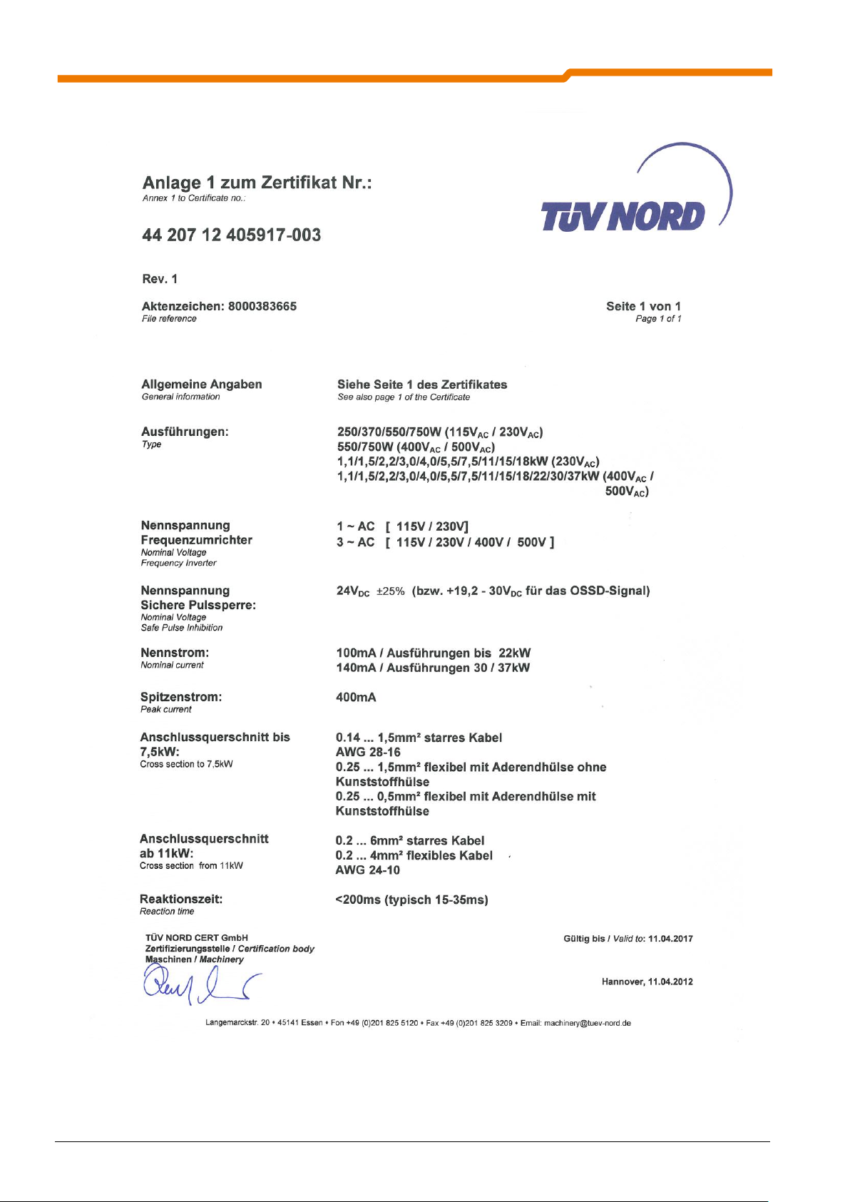
1.2 Approvals and certificates .................................................................................. 10
1.2.1 Certifications for the function STO .......................................................................... 11
1.2.2 Certifications for the function SS1 ................................................................ ........... 13
1.2.3 Certificate for the sole use of the digital inputs ........................................................ 15
1.3 Identification system ........................................................................................... 17
2 FUNCTION DESCRIPTION .................................................................................................... 19
2.1 Safe shut-down method ..................................................................................... 21
2.1.1 Safe pulse block ...................................................................................................... 21
2.1.2 Digital inputs ........................................................................................................... 21
2.2 Safety functions .................................................................................................. 22
2.2.1 Safe torque off, STO ............................................................................................... 22
2.2.2 Safe stop 1, SS1 ..................................................................................................... 22
2.3 Examples / Implementation ................................................................................ 23
2.3.1 STO function ........................................................................................................... 23
2.3.2 SS1 Function .......................................................................................................... 25
2.3.3 Simple restart block................................................................................................. 26
2.3.4 Example without safe shut-down method................................................................ 27
2.3.5 Ruling out wiring faults ............................................................................................ 28
3 ASSEMBLY AND INSTALLATION ........................................................................................ 29
3.1 Installation and assembly ................................................................................... 29
3.2 Wiring guidelines ................................................................................................ 29
3.3 Mains supply (X1-PE, L1, L2/N, L3) ................................................................... 29
3.4 Connecting the control cables ............................................................................ 29
3.4.1 Connecting the safe pulse block (X8 – VIS 24V, VIS 0V) ....................................... 30
3.4.2 Connection terminals .............................................................................................. 31
3.4.3 Details of the "Safe pulse block" control connections.............................................. 33
3.4.4 Details of the "Digital inputs" control connections ................................................... 34
3.4.5 Details of the "Digital outputs" control connections ................................................. 38
4 PARAMETERISATION ........................................................................................................... 40
5 PROTECTIVE SWITCHING DEVICES ................................................................................... 44
5.1 Output voltage .................................................................................................... 44
5.2 Switching capacity and current load ................................................................... 44
5.3 OSSD outputs, test pulse ................................................................................... 44
6 SAFETY CATEGORIES ......................................................................................................... 45
6.1 IEC 60204-1:2005 .............................................................................................. 45
6.2 IEC 61800-5-2:2007 ........................................................................................... 45
6.3 IEC 61508 ........................................................................................................... 45
6.4 ISO 13849-1:2006 .............................................................................................. 46
7 COMMISSIONING................................................................................................................... 47
8 DIAGNOSIS AND FAULTS .................................................................................................... 49
8.1 Diagnosis ............................................................................................................ 49
8.2 Faults .................................................................................................................. 49
8.2.1 Table of possible error messages ........................................................................... 49
8.2.2 Error display ............................................................................................................ 49
8.2.3 Error memory .......................................................................................................... 49
9 TECHNICAL DATA ................................................................................................................. 50
9.1 Environmental data............................................................................................. 50
9.2 Control terminal data .......................................................................................... 50
9.3 Data for the digital inputs .................................................................................... 51
9.4 Data for the safe pulse block .............................................................................. 52
BU 0530 GB-3712 7
Page 8

Functional safety with NORD SK 500E frequency inverters
10 ADDITIONAL INFORMATION ............................................................................................. 53
10.1 Maintenance and servicing information ........................................................... 53
10.2 Abbreviations in this manual ............................................................................ 53
11 KEYWORD INDEX ............................................................................................................... 54
8 BU 0530 GB-3712
Page 9
1 General
This manual BU 0530 ES describes the aspects that are directly related to the functional safety of the
equipment. All standard functions and parameters of the inverter are contained in the manual (BU 0500 GB).
1.1 Safety and installationinformation
SK 500E frequency inverters are equipment for use in industrial high voltage systems and are operated at
voltages that could lead to severe injuries or death if they are touched.
Installation and other work may only be carried out by qualified electricians and with the device
disconnected. The operating instructions must always be available to these persons and must
be strictly observed by them.
Local regulations for the installation of electrical equipment and accident prevention must be
complied with.
The equipment continues to carry hazardous voltages for up to 5 minutes after being switched
off at the mains. The equipment may only be opened or the cover or control element removed 5
minutes after the equipment has been disconnected from the power supply. All covers must be
put back in place before the mains voltage is switched back on again.
For single phase operation (115/230 V) the mains impedance must be at least 100H for each
conductor. If this is not the case, a mains choke must be installed.
1 General
For safe isolation from the mains, all poles of the supply cable to the frequency inverter must be
able to be disconnected.
Even during motor standstill (e.g. caused by an electronic block, blocked drive or output terminal
short circuit), the line connection terminals, motor terminals and braking resistor terminals may
still conduct hazardous voltages. A motor standstill is not identical to electrical isolation from the
mains.
Parts of the control board, and especially the connector socket for the removable technology
units also carry hazardous voltages. The control terminals are mains voltage free.
Note: with certain settings, the frequency inverter can start up automatically after the mains are
switched on.
The circuit boards contain highly-sensitive MOS semiconductor components that are particularly
sensitive to static electricity. Avoid touching circuit tracks and components with the hand or
metallic objects. Only the terminal strip screws may be touched with insulated screwdrivers when
connecting the cables.
The frequency inverter is only intended for permanent connection and may not be operated
without effective earthing connections which comply with the local regulations for large leakage
currents
(> 3.5 mA). VDE 0160 stipulates the installation of a second earthing conductor or an earthing
conductor cross-section of at least 10 mm2.
A universal leakage current-sensitive circuit breaker (type B) according to EN 50178/VDE 0160
must be used.
SK 500E frequency inverters are maintenance free. The cooling surfaces must be regularly
cleaned with compressed air if the ambient air is dusty.
Installation of the frequency inverter in an IP54 switching cabinet is mandatory.
The clamp cover must be used!
BU 0530 GB-3712 9
Page 10

Functional safety with NORD SK 500E frequency inverters
CAUTION
The heat sink and all other metal components can heat up to temperatures above 70 ℃.
When mounting, sufficient distance from neighbouring components must be maintained.
When working on the components, allow sufficient cooling time beforehand
Protection against accidental contact may need to be provided.
ATTENTION
DANGER TO LIFE!
The power unit can continue to carry voltages for up to 5 minutes after being switched off at
the mains. Inverter terminals, motor cables and motor terminals may carry voltage!
Touching open or free terminals, cables and equipment components can lead to severe injury
or death!
Work may only be carried out by qualified specialist electricians and with the electrical supply
to the equipment disconnected!
CAUTION
Children and the general public must be kept away from the equipment!
The equipment may only be used for the purpose intended by the manufacturer.
Unauthorised modifications and the use of spare parts and additional equipment which has
not been purchased from or recommended by the manufacturer of the device may cause fire,
electric shock and injury.
Keep these operating instructions in an accessible location and give them to all operators!
WARNING
This product is intended for use in an industrial environment and is subject to sales
restrictions according to IEC 61800-3. In a domestic environment, this product can cause
high frequency interference, in which case the user may be required to take appropriate
measures.
An appropriate measure would be the inclusion of a recommended mains filter.
1.2 Approvals and certificates
The certificates listed below refer to functional safety. Certifications relating to the frequency inverter (EMC,
UL, etc.) are listed in the main manual (BU0500).
The certificates for size 8 and 9 frequency inverters (45 ... 90kW) were not available at the time of
publication, however, they will be provided towards the end of 2012.
10 BU 0530 GB-3712
Page 11

1.2.1 Certifications for the function STO
1 General
BU 0530 GB-3712 11
Page 12

Functional safety with NORD SK 500E frequency inverters
12 BU 0530 GB-3712
Page 13

1.2.2 Certifications for the function SS1
1 General
BU 0530 GB-3712 13
Page 14

Functional safety with NORD SK 500E frequency inverters
14 BU 0530 GB-3712
Page 15

1.2.3 Certificate for the sole use of the digital inputs
1 General
BU 0530 GB-3712 15
Page 16
Functional safety with NORD SK 500E frequency inverters
16 BU 0530 GB-3712
Page 17
Name for ordering SK 5xxE
Example:
SK
520
E-
751
-
340-A
-
XXX
Configuration
500
5x dig. IN, 2x analog IN, 2x relay OUT, 1x analog OUT,
RS232/485
505*
as for "500", however 24 V supply for the control unit
510*
as for "500", but with additional "safe pulse block"
511*
as "510", but additionally with 2x CANbus/CANopen
515*
as for "510", however 24 V supply for the control unit
520
as "500", but additionally with 2x CANbus/CANopen, 2x dig. IN,
2x dig. OUT, incremental encoder input
525*
as for "520", however 24 V supply for the control unit
530
as for "520", however with additional "safe pulse block" and
positioning control
535
as for "530", however 24 V supply for the control unit
540
as for 530, however additionally with PLC functionality and
multi-encoder interface
545
as for "540", however 24 V supply for the control unit
Power
Mains
112
323-A
340-A
350-A
250
250W
I I
Size S
370
370W
1 1
550
550W
1 1 1
1
750
750W
1 1 1
1
111
1.1kW
2 2
2
151
1.5kW
2 2
2
221
2.2kW
2 2
2
301
3.0kW
3 3
3
401
4.0kW
3 3
3
551
5.5kW
5 4
4
751
7.5kW
5 4
4
112
11kW
6 5
5
152
15kW
7 5
5
182
18.5kW
7 6
6
222
22kW
6
6
302
30kW
7
7
372
37kW
7
7
452
45kW
8
8
552
55kW
8
8
752
75kW
9
9
902
90kW
9
9
1.3 Identification system
1 General
BU 0530 GB-3712 17
Page 18

Functional safety with NORD SK 500E frequency inverters
Name for ordering SK 5xxE
Example:
SK
520
E-
751
-
340-A
-
XXX
Mains
112-O
Single phase, 115V, without filter, only devices without "Safe
pulse block" (SK 500E, 505E, 520E and 525E, SK 530E only
position control)
323-A
3-phase, 230 V, internal A-filter (1/3 phases up to 2.2 kW)
340-A
3-phase, 400 V, internal A-filter
350-A*
3-phase, 500V, internal A-filter
Option
No option
CP
Cold Plate
XXX
Further options possible
* only available on request!
18 BU 0530 GB-3712
Page 19

2 Description of function
Sizes 1 - 4
Sizes 5 - 7
I/O
Emergency stop
µC
T5
T6
T3
T4
T1
T2
U
V
W
L1
L2
L3
Frequency Inverter
=
=
=
=
Control voltage
VIS 0V (88)
VIS 24V (89)
=
=
=
=
Safe pulse block
VOS 0V (87)
VOS 24V (86)
Driver
Logic
T1 T3 T5
Gate supply
T2 T4 T6
M
Gate supply
Driver
Internal power supply
Frequency inverter
Safe pulse block
Mains
Motor
I/O
Control
µC
T5
T6
T3
T4
T1
T2
U V W
M
L1
L2
L3
Logic
VI_S +24V
2 Function description
To avoid danger to persons and to prevent damage to material, machines must be able to be switched off
safely. The frequency inverters SK 510E, SK 511E, SK 515E, SK 530E, SK 535E, SK 540 and SK 545E
provide a method for safe switch-off (Safe pulse block).
In order to understand the function of the shut-down methods, it is first of all necessary to consider the function
of the frequency inverter.
The mains voltages are rectified and the resulting DC voltage is reconverted to AC according to the
requirements of the operating status of the motor (frequency and voltage).
Internal structure of the safe pulse block:
BU 0530 GB-3712 19
Page 20

Functional safety with NORD SK 500E frequency inverters
Sizes 7 - 9
I/O
Emergency stop
Driver
µC
T5
T6
T3
T4
T1
T2
U
V
W
L1
L2
L3
Frequency Inverter
Logic
=
=
=
=
Control voltage
Gate supply
VIS 0V (88)
VIS 24V (89)
VOS 0V (87)
VOS 24V (86)
Primary power
=
=
=
=
PWM-IC
=
=
PWM-IC
=
=
PWM-IC
M
Safe pulse block
The semiconductor switches of the inverter (T1 to T6) are controlled by a highly complex pulse pattern. This
pulse pattern is generated by the microcontroller (µC) and amplified by the driver. The drivers convert the logic
signals on the control voltages of the semiconductor switch. The semiconductor switches are switched via the
control voltage and the pulse pattern is amplified and applied to the motor terminals. Due to the low-pass effect
of the motor, a three-phase pulse width modulated sine wave voltage - a three-phase system, results from the
pulsed voltage. The motor generates a torque.
20 BU 0530 GB-3712
Page 21

2 Description of function
NOTE
On triggering the safe shut-down method, a mechanical brake connected to the terminals 1
(K1.1) and 2 (K1.2) can be applied (see parameter 434 in the BU 0500 GB manual). If the
drive unit is not previously switched off, the brake must be designed as an operational brake.
1
DIN1 ...
GND
DIN4
Frequency inverter
Filter
for
OSSD
optional
21
40
24V
Safety output
Safety output
24V
Safety output
24V
GND SH
24V SH
Frequency inverter
88
89
Safety output
24V
or
Safety output
24V
or
Safety output
24V
2.1 Safe shut-down method
With the aid of a safe shut-down method the torque is now to be safely shut down. This corresponds to the
safety function STO (safe torque off).
In order to switch off the torque, the current to the motor must be interrupted. The pulse block is provided for
this.
2.1.1 Safe pulse block
Devices equipped with a "safe pulse block" have an additional DC/DC converter, which produces the supply
voltage for the driver from a 24V supply (24V_SH, GND_SH).
If the external 24 V voltage is switched off then the DC/DC converter does not transmit any power to the
drivers. As the drivers are now no longer supplied with power, no control pulses reach the relevant
semiconductor switches of the inverter. The flow of current in the semiconductor switches and the motor is
interrupted. I.e. after a certain reaction time of the electronics and the reduction time of the motor current, the
motor does not develop a driving torque.
The switch-off of the 24V supply (24V_SH, GND_SH) must be carried out by a fail-safe switching device. For
this, either the connection 24V_SH (Terminal 89) or the connection GND_SH (Terminal 88) may be
disconnected from the 24V source. For preference, the 24V_SH connection is disconnected.
2.1.2 Digital inputs
In order to implement a safety function, the digital inputs can be used as auxiliary inputs, e.g. for the triggering
of a braking process. It should be noted that the digital inputs only fulfil minimum safety requirements. A safe
shut-down method is always required!
The digital inputs, other I/Os and the 24V supply have a common earth. This means that a digital input may
only be switched off by disconnecting the associated connection (21 for DIN1 to 24 for DIN 4). Switch-off via
GND is not possible!
When operating with an OSSD1 a filter is only required for environments with strong interference.
If only low levels of functional safety are required, the safety function can also be implemented with the digital
inputs. It is recommended that this is only considered if the risk assessment has shown that slight (normally
temporary) injuries could result on failure of the safety function (see also Section 6 ). In case of doubt, a safe
shut-down method should always be used.
Output Signal Switching Device
BU 0530 GB-3712 21
Page 22

Functional safety with NORD SK 500E frequency inverters
NOTE
Control of a mechanical brake by means of the inverter is not fail-safe!
A mechanical brake connected to terminals 1 (K1.1) and 2 (K1.2) can be applied on triggering
of the STO function. This means that in this case, the brake must be designed as an operating
brake, as the drive unit and all of its rotating mass is stopped by the mechanical brake.
Slippage of lifting gear when triggering the STO function must be prevented by suitable brakes
where necessary!
NOTE
Controlled braking is triggered via a digital input and only complies with low safety requirements!
If controlled braking fails then the device switches over to STO.
If necessary, the braking process must be monitored.
NOTE
Control of a mechanical brake by means of the inverter is not fail-safe!
In case of failure of controlled braking, a mechanical brake connected to terminals 1 (K1.1) and
2 (K1.2) may be overloaded, as this brake is applied when the STO function is triggered.
If necessary, slippage of lifting gear must be prevented by the use of suitable brakes.
2.2 Safety functions
A stop function can be executed by means of a safe shut-down method. As this has priority over other control
functions this stop-function is suitable for stopping in emergencies. This ensures that the torque is shut down
by means of a safe shut-down method. This function is known as "safe torque off" or STO.
It is also possible to first stop the motor in a controlled manner and then to switch off the torque. This function
is referred to as "safe stop 1" or SS1.
2.2.1 Safe torque off, STO
With the STO function the drive torque is switched off as quickly as possible (see Technical Data Reaction
Time) and the drive until (motor and machine) run down to a standstill. This behaviour corresponds to Stop
Category 0 (uncontrolled braking) as per EN 60204-1. A certain time therefore elapses until the drive unit does
not perform any further dangerous movements and a safe state is achieved. Monitoring of whether or when the
drive unit has achieved a safe state is not integrated into the frequency inverter.
According to the switching equipment used and with the use of a safe shut-down method, an STO function with
Safety Category 4 as per DIN EN ISO 13849-1 can be implemented.
2.2.2 Safe stop 1, SS1
With the SS1 function, the motor is first stopped by the inverter and after standstill the device switches to the
STO function. This method is the same as stop category 1 (controlled stop) as per IEC60204-1. Switching to
the STO function can be monitored after reaching standstill or can be carried out via a fail-safe timing relay
(delayed output of a protective switching device).
22 BU 0530 GB-3712
Page 23

2 Description of function
NOTE
If the "Safe pulse block" triggers for an enabled frequency inverter, error E018 (18.0 safety
circuit) is triggered.
DIN1
GND
24V SH
21
40
88
89
24V
24V
24V
Frequency inverter
Use of the
"Safe pulse block"
Reset
Emergency stop button
Reset circuit
Safety output 1
Safety output 2
Supply voltage
Input circuit
with short-
circuit detection
Shielded cable to
eliminate errors as per
DIN EN ISO 13849-2
Filter
for
OSSD
optional
GND SH
24V SH
88
89
24V
-
24V
Frequency inverter
Use of the
"Safe pulse block"
Reset
Emergency stop button
Reset circuit
Shielded cable to eliminate
errors as per
DIN EN ISO 13849-2
Input circuit
with shortcircuit
detection
Supply
voltage
Safety output
2.3 Examples / Implementation
The following illustrates several examples of solutions for the safety functions STO and SS1.
2.3.1 STO function
Normally, a protective switching device is used to implement a safety function. The safety category of the
function is determined by the component with the lowest category.
In this example, Safety Category 4 as per DIN ISO 13849-1 can be achieved. The prerequisite for this is that
the emergency stop button, the protective switching device and the wiring fulfil the requirements for Category
4. For example, this can be achieved as follows:
Redundant protective switching device with self-monitoring
Dual-channel input circuit with short-circuit recognition (and appropriate emergency stop button)
Safety output with periodic switch-off tests (OSSD)
Elimination of errors as per DIN ISO 13849-2 for the wiring between the switching device and the input
terminals of the safe shut-down method used, by the use of a shielded cable and connection of the
shield at both ends.
The typical reaction time can be reduced by the additional use of a digital input (e.g.: DIN1), which must be
parameterised for the function "Block voltage":
Note: The optional filter on the digital input is only required in environments with heavy interference.
A second safety output is required to control the digital input.
BU 0530 GB-3712 23
Page 24

Functional safety with NORD SK 500E frequency inverters
NOTE
A separate shielded cable must be used for the "safe pulse block" or "switch-off of the 24V
supply". When using a protective switching device with short-circuit monitored OSSD-outputs,
the safety outputs can be combined in a single cable.
NOTE
Only the "safe pulse block" or "switch-off of the 24V" supply fulfil the requirements of Safety
Category 4. This does not apply to the digital input.
The frequency inverter can only fulfil safety category 1 during the period between activation of
the safe pulse block via a digital input and activation via terminals 88 and 89.
This solution is preferable, especially in cases where the switching device only checks its safety outputs in the
course of an enabling cycle, as is the case with some electro-mechanical switching devices. A suitable
checking interval must be specified according to the safety requirements.
24 BU 0530 GB-3712
Page 25

2 Description of function
NOTE
A separate shielded cable must be used for the "safe pulse block" or "switch-off of the 24V
supply". When using a protective switching device with short-circuit monitored OSSD-outputs,
the safety outputs can be combined in a single shielded cable.
NOTE
The requirements of Safety Category 4 / Performance Level e can only be fulfilled with a safer
shut-down method. Safety Category 1 (and PL c) can be achieved for the digital inputs and
therefore for controlled braking.
DIN1
GND
GND SH
24V SH
21
40
88
89
24V
Reset
24V
24V
Filter
for
optional
Frequency inverter
Use of the
"Safe pulse block"
Emergency stop
Supply voltage
Reset circuit
Input circuit
with shortcircuit
detection
Safety output 1
Safety output 2
Shielded cable to eliminate
errors as per
DIN EN ISO 13849-2
2.3.2 SS1 Function
A digital input is always required for the implementation of the SS1 function in order to initiate a braking
process performed by the inverter. For this, the digital input used is set to the function "fast stop" [11].
Note: The optional filter on the digital input is only required in environments with heavy interference.
When the safety function is requested, a controlled stopping procedure is first triggered via the digital input (in
this case DIN1). Here it must be ensured that the drive is brought to standstill within the parameterised fast
stop time (P426). After the elapse of a delay time which is controlled by the switching device, the safe shutdown method is triggered. The delay time must be dimensioned so that the delay is longer than the fast stop
time plus the DC follow-up time (P559). The delay time must be selected so as to be fail-safe.
Here it should be noted that controlled braking can fulfil the requirements for Safety Category 1. Safety
Category 4 as per DIN EN ISO 13849-1 can be achieved with final switch-off by the triggering of a safe shutdown method "safe pulse block" or "switch-off of the 24V supply". For this, the same conditions as described in
the examples for the STO function apply. If controlled braking fails then the device switches over to STO (after
the set delay).
BU 0530 GB-3712 25
Page 26

Functional safety with NORD SK 500E frequency inverters
NOTE
After triggering the "safe pulse block“, the inverter shows the acknowledgeable fault E018 (18.0
Safety circuit).
NOTE
In this example, there is no reset circuit as is the case with the protective switching devices. If
the result of risk analysis is that cancellation of the stop command must be acknowledged by
intended manual action then the resetting requirements can be fulfilled organisationally (e.g. by
an emergency-stop button with key releasing device and storage of the key away from the
machine).
NOTE
We recommend that the "automatic fault clearance“ (P506) and "automatic start-up" (P428)
functions are not used in combination with each other (See BU 0500 GB), as the drive would
otherwise immediately start up after unlocking the emergency-off button.
GND SH
24V SH
Frequency inverter
89
Emergency stop button
24V
Shielded cable to eliminate
errors as per
DIN EN ISO 13849-2
88
2.3.3 Simple restart block
Safety Category 4 as per DIN ISO 13849-1 can be achieved with a direct dual-channel triggering of the "safe
pulse block" with the aid of a safe switching element. The following illustration shows an example with an
emergency stop switch (guided contacts, Safety Category 4).
To achieve safety category 4, fault exclusion as per EN 13849-2 Sec. D.5 must be possible for the upstream
components (hard-wiring and dual-channel buttons with independent, positive-opening contacts). I.e., in this
example, the emergency-stop button and the wiring must be designed in such a way that short-circuiting at the
emergency-stop button and to other live systems can be ruled out.
26 BU 0530 GB-3712
Page 27

2 Description of function
NOTE
As a maximum, this example achieves Safety Category 1 or Performance Level c. This circuit
version is not SIL-capable
(See Section 6).
DIN1 ...
GND
DIN4
40
24
24V
Reset
24V
Frequency inverter
optional
Emergency stop button
Reset circuit
Safety output
Use of a
digital input
STO: P420[-01...-04]=10, "Disable voltage"
SS1: P420[-01...-04]=11, "Fast stop"
Filter
for
OSSD
Shielded cable to eliminate
errors as per
DIN EN ISO 13849-2
Supply voltage
Input circuit
with shortcircuit
detection
2.3.4 Example without safe shut-down method
It is possible to implement the safety functions STO or SS1 with a digital input and a protective switching
device. With this switching version, as a maximum, Safety Category 1 as per DIN EN ISO 13849-1 can be
achieved, if in addition to the digital inputs, all other components (protective switching device, emergency stop
button, wiring) fulfil the requirements for Category 1.
This switching version should only be considered if only low requirements for functional safety need to be
fulfilled and if the risk assessment has shown that failure of the safety function can only result in slight (usually
temporary) injuries (see also Section 6 ). In case of doubt, the "Safe pulse block" should always be used.
Note: The optional filter is only required in environments with heavy interference.
To implement the safety function STO, the digital input is parameterised to the function "Disable voltage".
With the safety function SS1 the digital input is assigned the function "Fast stop" (parameter P420[-01...-04])
and the fast stop time is set via parameter P426. It must be ensured that the drive is brought to standstill within
the parameterised fast stop time.
BU 0530 GB-3712 27
Page 28

Functional safety with NORD SK 500E frequency inverters
GND SH
24V SH
88
89
24V
Frequency inverter
Safety output 1
Safety output 2
Monitored outputs
DIN1
GND
21
40
24V
optional
Safety output 1
Filter
for
OSSD
24V SH
GND SH
89
88
24V
Safety output 2
Monitored outputs
without short-circuit detection
Frequency inverter
DIN1
GND
21
40
24V
optional
Safety output 1
Filter
for
OSSD
24V SH
GND SH
89
88
24V
Safety output 2
Monitored outputs
without short-circuit
Frequency inverter
2.3.5 Ruling out wiring faults
In the examples above, a separate shielded cable, whose shield is connected at both ends is used each of the
inputs used for the implementation of the safety function. This measures serves to rule out faults as per DIN
EN ISO 13849-1 in case of a short circuit between any of the conductors. This exclusion of faults is necessary
in order to fulfil the requirements of Safety Category 4 as per DIN EN ISO 13849-1. According to this, a single
detected fault or an accumulation of undetected faults must not lead to the loss of the safety function. A short
circuit from an external voltage, e.g. from a 24V control cable, to the 24V input of a safe shut-down method
could lead to the loss of a safety function. I.e. this fault must be prevented by means of suitable measures.
The use of a separate shielded cable for each input is not mandatory. For example, the cables for the digital
inputs and the safe shut-down method may be jointly laid in a shielded cable, if the monitored safety outputs of
the switching device is equipped with short-circuit detection (See Fig.). If necessary, the effectiveness of the
short-circuit detection must be demonstrated.
Other measures (separate cable duct, installation in armoured conduit) are possible. More precise details
result from the risk assessment and the FMEA for the specific application.
For the "safe pulse block" it is also conceivable that this is triggered via two safety outputs, one switching the
24V output and the other switching the GND output.
In this case a shielded cable is not strictly necessary if both safety outputs are monitored. If, for example, other
24V control cables are laid in the same cable duct and an error in the form of a short-circuit from 24V_SH to a
control cable (=24V) is assumed, this fault would be detected by the output monitoring of the switching device
and the "safe pulse block" would be triggered by the second safety output. More precise details result from the
FMEA for the specific application.
If a shielded cable is not used for the wiring of the safety function, the effects of electromagnetic fields may
need to be taken into account. Hence the use of a 1 m long cable (in a separate cable duct) in an environment
without strong electromagnetic fields is relatively safe, while the installation of a long cable in the direct vicinity
of a powerful transmitter or a medium voltage distributor may cause the failure of the safety function. Because
of this, the use of shielded cables is generally recommended.
28 BU 0530 GB-3712
Page 29

3 Assembly and installation
3 Assembly and installation
The installation instructions contained within this manual only deal with issues that are related to functional
safety. Additional information is contained in the manual (BU 0500 DE).
3.1 Installation and assembly
SK 5xxE series frequency inverters have protection class IP20 and may only be installed in an area with
protection class IP54 (or higher).
The installation instructions contained in BU0500 GB must be observed!
3.2 Wiring guidelines
With regard to this item, please observe the appropriate chapter of BU 0500 DE and the following chapters in
this manual.
3.3 Mains supply (X1-PE, L1, L2/N, L3)
devices with "safe pulse block“ may only be operated at TN networks, TT networks and grounded corner! The
equipment has not been designed for operation at IT networks.
3.4 Connecting the control cables
Detailed information regarding the connection of the control cables (terminal designation, terminal positions
etc) can be found in the main manual for the frequency inverter (BU0500).
BU 0530 GB-3712 29
Page 30

Functional safety with NORD SK 500E frequency inverters
q
l
R
CU
*
km
mm
CU
2
*19
5,0R
VAInumberRU
PeakINFUcable
14,0*5*5,0**
,
3.4.1 Connecting the safe pulse block (X8 – VIS 24V, VIS 0V)
SK 51xE SK 53xE and SK 54xE series frequency inverters are equipped with the option "Functional safety".
Connection of the corresponding control cables is made via terminal block X8. Up to and including size 4, this
terminal block and all other control connections are located under the front cover (See Section 3.4.2
"Connection terminals"). For sizes 5 to 7, the terminal block X8 is located on the underside of the frequency
inverter (motor output side).
A two-wire shielded cable must be used for the safe pulse block. The shield must be connected at on both
ends. For mechanical switching devices the line drop in the cable must not exceed ΔU
electronic protective switching devices it must not exceed ΔU
I
= 400 mA should be assumed.
IN,Peak
Operation at OSSD
The safe pulse block is specially designed for use with an OSSD.
The capacity between the wires (including the shielded capacities) must not exceed a value of 20nF for each
inverter connected.
Additional restrictions may apply here with regard to the protective switching device.
EMC
When the „safe pulse block“ has been wired correctly for EMC, the recommended EMC values (See BU 0500
GB) can be complied with up to a cable length of 20m between the safety switching device and the inverter.
Multi-device operation
When operating several inverters at one safety switching device, the switching capacity of the switching device
and the load rating of the 24V power-feeding supply must be observed.
The shield must be applied to all inverters.
The permissible line drops on the cable must be observed!
Example:
≤ 1 V. For the calculation, a peak current of
Cable
≤ 3 V and for
Cable
5x frequency inverter at an electronic safety switching device!
The 5x FIs are arranged next to each other in a switching cabinet
20m must be bridged between the FI and the switching device!
Shielded cable 2x1.5 mm2
with
Double the length of cable must be used because line drops occur in both wires.
=> OK!
30 BU 0530 GB-3712
Page 31

3.4.2 Connection terminals
Frequency inverter
Size 1 ... 4 and 8 ... 9
Rigid cable cross-section
0.14 … 1.5mm²
Flexible cable cross-section
0.14 … 1.5mm²
AWG standard
AWG 28-16
Flexible cable cross section with wire end sleeve, without plastic tube
0.25 … 1.5mm²
Flexible cable cross section with wire end sleeve, and with plastic tube
0.25 … 0.5mm²
Nominal ratings of safe pulse block
Terminal X8:86
(output - provision of +15V / +24V)
+24 V
(max. 300mA)
Terminal X8:87
GND
Terminal X8:88
GND
Terminal X8:89
(Input: “Safe pulse block”)
+24 V ± 25% or
+24 V -20% + 25% for operation with OSSD
2
100mA (AV) (Size 1 - 4)
50mA (AV) (Size 8 - 9)
400mA (peak) after switching-on or after
a test pulse from an OSSD
2
CAUTION: For this safe pulse block function,
the bridges must be removed!
As delivered, terminals 87-88 and 86-89 are
bridged in order to enable commissioning or
operation without the safety function (or ext. 24V).
X8: VIS 24V 24V
input of pulse block
NOTE:
15V output for commissioning
without safety switching device
or safety function.
NOTE:
For size V and above, the ter-
minal block X8 is located on the
motor output side of the fre-
quency inverter.
3 Assembly and installation
Connection terminals: Plug-in clip connectors can be released with a small screwdriver
Deviating position of terminal block X8 for sizes 5 to 7
Output Signal Switching Device
BU 0530 GB-3712 31
Page 32

Functional safety with NORD SK 500E frequency inverters
Frequency inverter
Sizes 5 ... 7
Rigid cable cross-section
0.2 … 6mm²
Flexible cable cross-section
0.2 … 4mm²
AWG standard
AWG 24-10
Tightening torque
for screw terminals
0.5 … 0.6Nm
Nominal ratings of safe pulse block
Terminal X8:86
(output - provision of +24V)
+24 V
(max. 300mA)
Terminal X8:87
GND
Terminal X8:89
(Input: “Safe pulse block”)
+24 V ± 25%
100mA (AV) (Size 5 - 6)
140mA (AV) (Size 7)
400mA (peak) after switching-on or after
a test pulse from an OSSD
Terminal X8:88
GND
In deviation from the illustration above, from size
5 and above, the position of terminal block X8 for
the connection of the safe pulse block is located
on the underside of the device (motor connection
side).
Connection data:
32 BU 0530 GB-3712
Page 33

3.4.3 Details of the "Safe pulse block" control connections
NOTE
As delivered, for commissioning without safety switching device, terminals 87-88 and 86-89 are
bridged. In order to be able to use the safety function, the bridges must be removed.
Relevance
SK 500E
SK 505E
SK 510E
SK 511E
SK 515E
SK 520E
SK 530E
SK 535E
SK 540E
SK 545E
√
√
√ √
Terminal X8:
86
87
88
89
VO_S 15V
VO_S 0V
VI_S 0V
VI_S 24V
Designation
Terminal
Function
[factory setting]
Data
Description / wiring suggestion
Parameter
up to SK
535E
SK 540E
and above
86
Supply voltage
15V 20%
When setting-up without using a
safety function, wire directly to V_IS
24V.
P420 et
seqq.
P420 [-…]
87
Reference potential
88
Reference potential
24V 25%, ≤140mA
See technical data in
BU0530!
Fail-safe input
89
Input,
safe pulse lock
Relevance
SK 500E
SK 505E
SK 510E
SK 511E
SK 515E
SK 520E
SK 530E
SK 535E
SK 540E
SK 545E
√
√
√
Terminal X8:
86
87
88
89
VO_S 24V
VO_S 0V
V_S 0V
VI_S 24V
Designation
Terminal
Function
[factory setting]
Data
Description / wiring suggestion
Parameter
up to SK
535E
SK 540E
and above
86
Supply voltage
18-30V, each to VI
24V
When setting-up without using a
safety function, wire directly to V_IS
24V.
P420 et
seqq.
P420 […]
87
Reference potential
88
Reference potential
24V 25%, ≤140mA
See technical data in
BU0530!
Fail-safe input
89
Input,
safe pulse lock
Terminal block X8 – Safe pulse lock (not with 115V devices)
3 Assembly and installation
BU 0530 GB-3712 33
Page 34

Functional safety with NORD SK 500E frequency inverters
NOTE
AGND and DGND are common reference potentials for analog or digital inputs.
5V / 15V can be collected by several terminals if required. The sum of collected currents must
not exceed 250mA / 150mA.
Relevance
SK 500E
SK 505E
SK 510E
SK 511E
SK 515E
SK 520E
SK 530E
SK 535E
SK 540E
SK 545E
√ √
√ √
√
Terminals X5:
21
22
23
24
25
42
40
41
DIN1
DIN2
DIN3
DIN4
DIN5
VO 15V
GND / 0V
VO 5V
Designation
Terminal
Function
[factory setting]
Data
Description / wiring suggestion
Parameter
up to
SK 535E
21
Digital input 1
[ON right]
7.5...30V, Ri=6.1k
Not suitable for
thermistor evaluation.
HTL encoders can only
be connected to DIN2
and DIN4
Limiting frequencies:
max. 10 kHz
min. 15 Hz
Each digital input has a reaction time
of ≤ 5ms.
Control with internal 15V:
21
22
23
24
25
42
40
41
15V
motor - PTC
Control with external 7.5-30V:
21
22
23
24
25
42
40
41
7.5 … 30V
motor - PTC
GND / 0V
P420
22
Digital input 2
[ON left]
P421
23
Digital input 3
[parameter set bit0]
P422
24
Digital input 4
[Fixed frequency 1,
P429]
P423
25
Digital input 5
[no function]
2.5...30V, Ri=2.2k
Not suitable for
evaluation of a safety
device.
Suitable for thermistor
evaluation with 5V.
NOTE: For the motor
thermistor P424 = 13
must be set.
P424
42
15V supply voltage
output
15V 20%
Supply voltage provided by the
frequency inverter for connection to
the digital inputs or the supply of a
10-30V encoder.
40
Reference potential
for digital signals
0V digital
Reference potential
41
5V supply voltage
output
5V 20%
Voltage supply for motor-PTC
3.4.4 Details of the "Digital inputs" control connections
Terminal block X5 – Digital In
34 BU 0530 GB-3712
Page 35

3 Assembly and installation
Relevance
SK 500E
SK 505E
SK 510E
SK 511E
SK 515E
SK 520E
SK 530E
SK 535E
SK 540E
SK 545E
√
√
√
Terminals X5:
21
22
23
24
25
44*
40
41
* Terminal 44:
up to Size 4: VI
Size 5 and above:
VO
DIN1
DIN2
DIN3
DIN4
DIN5
V…
24V
GND /
0V
VO 5V
Designation
Terminal
Function
[factory setting]
Data
Description / wiring suggestion
Parameter
up to
SK 535E
21
Digital input 1
[ON right]
7.5...30V, Ri=6.1k
Not suitable for
thermistor evaluation.
HTL encoders can
only be connected to
DIN2 and DIN4
Limiting frequencies:
max. 10 kHz
min. 15 Hz
Each digital input has a reaction
time of ≤ 5ms.
21
22
23
24
25
44
40
41
18 … 30V
motor - PTC
GND / 0V
P420
22
Digital input 2
[ON left]
P421
23
Digital input 3
[parameter set bit0]
P422
24
Digital input 4
[Fixed frequency 1,
P429]
P423
25
Digital input 5
[no function]
Only S1 – S4
2.5...30V, Ri=2.2k
Not suitable for
evaluation of a safety
device.
Suitable for thermistor
evaluation with 5V.
NOTE: For the motor
thermistor P424 = 13
must be set.
Above Size 5
Thermistor on
X13:T1/T2
P424
44
Size 1 to Size 4
VI 24V supply
voltage input
18…30V
at least 800mA (input)
Voltage supply for the FI control unit.
This is essential for the function of
the frequency inverter.
Size 5 and above
VO 24V supply
voltageoutput
24V ± 25%
max. 200mA (output)
Supply voltage provided by the
frequency inverter for connection to
the digital inputs or the supply of a
10-30V encoder.
The 24V control voltage is
generated by the FI, however it can
also be supplied via the terminals
X12:44/40. Supply via terminal
X5:44 is not possible.
40
Reference potential
for digital signals
0V digital
Reference potential
41
5V supply voltage
output
5V 20%
Voltage supply for motor-PTC
BU 0530 GB-3712 35
Page 36

Functional safety with NORD SK 500E frequency inverters
Relevance
SK 500E
SK 505E
SK 510E
SK 511E
SK 515E
SK 520E
SK 530E
SK 535E
SK 540E
SK 545E
√
Terminals X5:
21
22
23
24
39
38
42
40
DIN1
DIN2
DIN3
DIN4
TF-
TF+
VO 15V
GND / 0V
Designation
Terminal
Function
[factory setting]
Data
Description / wiring suggestion
Parameter
SK 540E
and above
21
Digital input 1
[ON right]
7.5...30V, Ri=6.1k
Not suitable for
thermistor evaluation.
HTL encoders can
only be connected to
DIN2 and DIN4
Limiting frequencies:
max. 10 kHz
min. 15 Hz
Each digital input has a reaction
time of ≤ 5ms.
Control with internal 15V:
21
22
23
24
39
38
42
40
motor - PTC
15V
Control with external 7.5-30V:
21
22
23
24
39
38
42
40
motor - PTC
GND / 0V
7.5 … 30V
P420 [-01]
22
Digital input 2
[ON left]
P420 [-02]
23
Digital input 3
[parameter set bit0]
P420 [-03]
24
Digital input 4
[Fixed frequency 1,
P429]
P420 [-04]
39
Thermistor input -
potential isolated
thermistor input, which
cannot be disabled,
for monitoring the
motor temperature
with a PTC
38
Thermistor input +
42
15V supply voltage
output
15V 20%
Supply voltage provided by the
frequency inverter for connection to
the digital inputs or the supply of a
10-30V encoder.
40
Reference potential
for digital signals
0V digital
Reference potential
36 BU 0530 GB-3712
Page 37

3 Assembly and installation
Relevance
SK 500E
SK 505E
SK 510E
SK 511E
SK 515E
SK 520E
SK 530E
SK 535E
SK 540E
SK 545E
√ Terminals X5:
21
22
23
24
39
38
44
40
DIN1
DIN2
DIN3
DIN4
TF-
TF+
VI 24V
GND / 0V
Designation
Terminal
Function
[factory setting]
Data
Description / wiring suggestion
Parameter
SK 540E
and above
21
Digital input 1
[ON right]
7.5...30V, Ri=6.1k
Not suitable for
thermistor evaluation.
HTL encoders can
only be connected to
DIN2 and DIN4
Limiting frequencies:
max. 10 kHz
min. 15 Hz
Each digital input has a reaction
time of ≤ 5ms.
21
22
23
24
39
38
44
40
motor - PTC
GND / 0V
18 … 30V
P420 [-01]
22
Digital input 2
[ON left]
P420 [-02]
23
Digital input 3
[parameter set bit0]
P420 [-03]
24
Digital input 4
[Fixed frequency 1,
P429]
P420 [-04]
39
Thermistor input -
potential isolated
thermistor input, which
cannot be disabled,
for monitoring the
motor temperature
with a PTC
38
Thermistor input +
44
24V supply voltage
input
18…30V
at least 800mA (input)
Voltage supply for the FI control unit.
This is essential for the function of
the frequency inverter.
40
Reference potential
for digital signals
0V digital
Reference potential
BU 0530 GB-3712 37
Page 38

Functional safety with NORD SK 500E frequency inverters
Relevance
SK 500E
SK 505E
SK 510E
SK 511E
SK 515E
SK 520E
SK 530E
SK 535E
SK 540E
SK 545E
√
√ √
Terminals X7:
73
74
26
27 5 7
42
40
RS485 +
RS485 -
DIN6
DIN7
DOUT1
DOUT2
VO 15V
GND / 0V
Designation
Terminal
Function
[factory setting]
Data
Description / wiring suggestion
Parameter
up to
SK 535E
SK 540E
and above
73
Data cable RS485
Baud rate
9600…38400Baud
Termination resistor
R=120
BUS connection parallel to RS485
on RJ12 plug
NOTE: The termination resistance of
DIP switch 1 (see RJ12/RJ45) can
also be used for terminal 73/74.
P503
P509
P503
P509
74
26
Digital input 6
[no function]
7.5...30V, Ri=3.3k
As described for terminal block X5,
DIN1 to DIN5.
Not suitable for the evaluation of a
motor thermistor.
P425
P420 [-06]
27
Digital input 7
[no function]
P470
P420 [-07]
Only SK 54xE
Alternatively:
Output 5 (DOUT3)
[no function]
Digital output
15V, max. 20mA
max. 100k load
With SK 54xE the digital input
(DIN7) can also be used as a digital
output (DOUT3).
If P434 [-05] and P420 [-07] are
parameterised with functions, a High
signal of the DOUT function results
in a High signal for the DIN function.
P434 [-05]
5
Output 3 (DOUT1)
[no function]
For evaluation in a control system.
The scope of functions corresponds
to that of the relay (P434).
P450
P434 [-03]
7
Output 4 (DOUT2)
[no function]
P455
P434 [-04]
Only SK 54xE
Alternatively:
Digital input 8
[no function]
7.5...30V, Ri=3.3k
With SK 54xE the digital output
(DOUT2) can also be used as a
digital input (DIN3).
If P434 [-04] and P420 [-10] are
parameterised with functions, a High
signal of the DOUT function results
in a High signal for the DIN function.
P420 [-10]
42
15V supply voltage
output
15V 20%
Voltage supply for connection to the
digital inputs or the supply of a 1030V encoder
40
Reference potential
for digital signals
0V digital
3.4.5 Details of the "Digital outputs" control connections
A digital output can be used to indicate the status of the "safe pulse block". It must be noted that this status
indication is not fail-safe.
Terminal block X/ – Digital I/O
38 BU 0530 GB-3712
Page 39

3 Assembly and installation
Relevance
SK 500E
SK 505E
SK 510E
SK 511E
SK 515E
SK 520E
SK 530E
SK 535E
SK 540E
SK 545E
√
√ Terminals X7:
73
74
26
27 5 7
44*
40
* Terminal 44:
up to Size 4: VI
Size 5 and above:
VO
485+
RS485 -
DIN6
DIN7
DOUT1
DOUT2
V… 24V
GND / 0V
Designation
Terminal
Function
[factory setting]
Data
Description / wiring suggestion
Parameter
up to
SK 535E
SK 540E
and above
73
Data cable RS485
Baud rate
9600…38400Baud
Termination resistor
R=120
BUS connection parallel to RS485
on RJ12 plug
NOTE: The termination resistance of
DIP switch 1 (see RJ12/RJ45) can
also be used for terminal 73/74.
P503
P509
P503
P509
74
26
Digital input 6
[no function]
7.5...30V, Ri=3.3k
As described for terminal block X5,
DIN1 to DIN5.
Not suitable for the evaluation of a
motor thermistor.
P425
P420 [-06]
27
Digital input 7
[no function]
P470
P420 [-07]
Only SK 54xE
Alternatively:
Output 5 (DOUT3)
[no function]
Digital output
S1 to S4
18-30V according to
VI 24V, max. 20mA,
max. 100k load
Above Size 5
DOUT1 and DOUT2:
24V, max. 200mA
max. 100k load
With SK 54xE the digital input
(DIN7) can also be used as a digital
output (DOUT3).
If P434 [-05] and P420 [-07] are
parameterised with functions, a High
signal of the DOUT function results
in a High signal for the DIN function.
P434 [-05]
5
Output 3 (DOUT1)
[no function]
For evaluation in a control system.
The scope of functions corresponds
to that of the relay (P434).
P450
P434 [-03]
7
Output 4 (DOUT2)
[no function]
P455
P434 [-04]
Only SK 54xE
Alternatively:
Digital input 8
[no function]
7.5...30V, Ri=3.3k
With SK 54xE the digital output
(DOUT2) can also be used as a
digital input (DIN3).
If P434 [-04] and P420 [-10] are
parameterised with functions, a High
signal of the DOUT function results
in a High signal for the DIN function.
P420 [-10]
44
Size 1 to Size 4
VI 24V supply
voltage input
18…30V
at least 800mA (input)
Voltage supply for the FI control unit.
This is essential for the function of
the frequency inverter.
Size 5 and above
VO 24V supply
voltageoutput
24V ± 25%
max. 200mA (output)
Supply voltage provided by the
frequency inverter for connection to
the digital inputs or the supply of a
10-30V encoder.
The 24V control voltage is
generated by the FI, however it can
also be supplied via the terminals
X12:44/40. Supply via terminal
X7:44 is not possible.
40
Reference potential
for digital signals
0V digital
BU 0530 GB-3712 39
Page 40

Functional safety with NORD SK 500E frequency inverters
ATTENTION
to implement the STO function, the "block voltage"function [10] must be assigned to the
appropriate parameter (P420 [-01]…[-04], depending on the digital input selected (DIN1 … DIN4).
For the SS1 function, the "fast stop" function [11] is assigned to the appropriate parameter. In
addition, the stopping time must be entered in parameter P426 and the DC run-on time must be
entered in parameter P559.
For function SS1, the fast stop time (P426) must be rated so that the drive is stopped within this
time. The DC follow-up time follows after the fast stop time (see above). The delay time of the
delayed output of the protective switching device must be rated so that it is longer than the fast
stop time plus the DC follow-up time.
Parameter
Setting value / Description / Note
Device
Supervisor
Parameter set
P420
Digital input 1
(Digital input 1)
up to
SK 535E
0 ... 74
{ 1 }
Enable right as factory setting, control terminal 21 (DIN1)
Various functions can be programmed. These can be seen in the following table.
P420 [-01]
...
[-10]
Digital inputs
(Digital input functions)
SK 540E and
above
0 ... 80
{ [-01] = 1 }
{ [-02] = 2 }
{ [-03] = 8 }
{ [-04] = 4 }
all other { 0 }
Up to 10 inputs which can be freely programmed with digital functions are available in the SK
54xE. Of these inputs, analog inputs 1 and 2 of the frequency inverter do not comply with
EN61131-2 (Type 1 digital inputs).
[-01] = Digital input 1 (DIN1): Enable right, (default), Terminal 21
[-02] = Digital input 2 (DIN2): Enable left, (default), Terminal 22
[-03] = Digital input 3 (DIN3): Parameter switching, (default), Terminal 23
[-04] = Digital input 4 (DIN4): Fixed frequency 1 (P429), (default), Terminal 24
[-05] = Digital input 5 (DIN5): No function, (default), Terminal 253
[-06] = Digital input 6 (DIN6): No function, (default), Terminal 26
[-07] = Digital input 7 (DIN7): No function, (default), Terminal 274
[-08] = Digital function Analog1 (AIN1), "Digital function of analog input 1": Terminal 145
[-09] = Digital function Analog2 (AIN2), "Digital function of analog input 2": Terminal 16c
[-10] = Digital input 8 (DIN8): No function, (default), Terminal 7b
P421
Digital input 2
(Digital input 2)
up to SK
535E
0 ... 74
{ 2 }
Enable left as factory setting, control terminal 22 (DIN2)
Various functions can be programmed. These can be seen in the following table.
P422
Digital input 3
(Digital input 3)
up to SK
535E
0 ... 74
{ 8 }
Parameter set switching Bit 0 as factory setting, control terminal 23 (DIN3)
Various functions can be programmed. These can be seen in the following table.
3
4
5
4 Parameterisation
In this manual, only those parameters and configurations are listed, which are of immediate significance to
functional safety. For additional information, please observe the instructions in manual BU 0500 GB.
Parameter list
Up to and including Size 4, digital input 5 is not available. In place of this a potential-free isolated thermistor input is implemented, whose function cannot be
disabled. If no thermistor is present the two terminals TF- and TF+ must be bridged. Parameterisation of this input does not have any effect.
Digital input 7 (DIN7) can also be used as digital output 3 (DOUT3 / Binary output 5). It is recommended that either an input function (P420 [-07] or an output
function (P434 [-05]) is parameterised. However, if and input function and an output function are parameterised, a High signal from the output function will result in the activation of the input function. This IO-exclusion is hence used as a kind of "flag". This also applies for digital input 8 (DIN8) and digital output 2
(DOUT2 / binary output 4).
The analog inputs 1 and 2 (AIN1 / 2) can also process digital functions. Care must be taken that either an analog function (P400 [-01]/[-02]) or a digital function (P420 [-08]/[-09]) is parameterised in order to prevent misinterpretation of the signals.
40 BU 0530 GB-3712
Page 41

4 Parameterisation
Parameter
Setting value / Description / Note
Device
Supervisor
Parameter set
P423
Digital input 4
(Digital input 4)
up to
SK 535E
0 ... 74
{ 4 }
Fixed frequency 1 (P429) as factory setting, control terminal 24 (DIN4)
Various functions can be programmed. These can be seen in the following table.
P425
Digital input 6
(Digital input 6)
From SK 520E
to SK 535E
0 ... 74
{ 0 }
No function as factory setting, control terminal 26 (DIN6)
Various functions can be programmed. These can be seen in the following table.
P426
Quick stop time
(Quick stop time)
P
0 ... 320.00 s
{ 0.10 }
Setting of the stop time for the fast stop function which can be triggered either via a digital input,
the bus control, the keyboard or automatically in case of a fault.
The emergency stop time is the time for the linear frequency decrease from the set maximum
frequency (P105) to 0Hz. If an actual setpoint <100% is being used, the emergency stop time is
reduced correspondingly.
P434
Relay 1 function
(Analog output 1 function (Relay 1– MFR1))
up to SK
535E
P
0 ... 39
{ 1 }
Control terminals 1/2:Settings 3 to 5 and 11 work with a 10% hysteresis, i.e. the relay contact
closes (Function 11 opens) when the limit value is reached and opens (function 11 closes) when a
10% smaller value is undershot. This behaviour can be inverted with a negative value in P435.
Various functions can be programmed. These can be seen in the following table.
BU 0530 GB-3712 41
Page 42

Functional safety with NORD SK 500E frequency inverters
Parameter
Setting value / Description / Note
Device
Supervisor
Parameter set
P434 [-01]
...
[-05]
Digital output function
(Digital output function)
SK 540E and
above
P
0 ... 39
{ [-01] = 1 }
{ [-02] = 7 }
all other { 0 }
Up to 5 outputs (2 of which are relays), which can be freely programmed with digital functions are
available in the SK 54xE. These can be seen in the following table.
[-01] = Output 1 / MFR1, relay output 1: external brake, (default), Terminals 1/2
[-02] = Output 2 / MFR2, relay output 2: Fault, (default), Terminals 3/4
[-03] = Output 3 / DOUT1, digital output 1: No function, (default), Terminal 5
[-04] = Output 4 / DOUT2, digital output 2: No function, (default), Terminal 76
[-05] = Output 5 / DOUT3, digital output 3: No function, (default), Terminal 27a
P441
Relay 2 function
(Output 2 function (Relay 2 - MFR2))
up to
SK 535E
P
0 ... 39
{ 7 }
Control terminals 3/4: Functions are identical to P434!
P450
Relay 3 function
(Function output 3 (DOUT1)) )
from SK 520E
to SK 535E
P
0 ... 39
{ 0 }
Control terminals 5/40: Functions are identical to P434! Digital output, 15V against DGND (for
SK 5x5E devices, deviations of the signal level are possible).
P455
Relay 4 function
(Function output 4 (DOUT2))
from SK 520E
to SK 535E
P
0 ... 39
{ 0 }
Control terminals 7/40: Functions are identical to P434! Digital output, 15V against DGND (for
SK 5x5E devices, deviations of the signal level are possible).
P470
Digital input 7
(Digital input 7)
from SK 520E
to SK 535E
0 ... 74
{ 0 }
No function as factory setting, control terminal 27 (DIN7)
Various functions can be programmed. These can be found in the tables for P420…P425.
P559
DC Run-on time
(DC run-on time)
S P
0.00 ... 30.00 s
{ 0.50 }
Following a stop signal and the braking ramp, a direct current is briefly applied to the motor to
fully bring the drive to a stop. Depending on the inertia, the time for which the current is applied
can be set in this parameter.
The current level depends on the previous braking procedure (current vector control) or the static
boost (linear characteristic).
6
Digital input 7 (DIN7) can also be used as digital output 3 (DOUT3 / Binary output 5). It is recommended that either an input function (P420 [-07] or an out-
put function (P434 [-05]) is parameterised. However, if and input function and an output function are parameterised, a High signal from the output function will
result in the activation of the input function. This IO-exclusion is hence used as a kind of "flag". This also applies for digital input 8 (DIN8) and digital output 2
(DOUT2 / binary output 4).
42 BU 0530 GB-3712
Page 43

4 Parameterisation
Value
Function
Description
Signal
00
No function
Input switched off.
-----
10
Disable voltage 7
The FI output voltage is switched off; the motor runs down freely.
Low
11
Fast stop ³
The FI reduces the frequency according to the programmed fast stop time
P426.
Low
Valu
e
Function
Description
Signal*
00
No function
Input switched off.
Low
01
External brake
For the control of a mechanical brake on the motor. The relay switches at
a programmed absolute minimum frequency (P505). For typical brakes a
setpoint delay of 0.2 … 0.3 seconds (see also P107) should be
programmed.
A mechanical brake can be directly AC switched. (Please note the technical specifications of the relay contacts)
High
07
Fault
General fault message, fault is active or not yet acknowledged.
Error – contact opens
(ready – contact closes)
Low
39
STO inactive
The relay / bit deactivates if STO or the Safe Stop are active.
High
* For relay contacts (High = "Contact closed", Low = "Contact open")
7
List of the functions or the digital inputs P420 ... P425, P470 which are relevant to "Functional safety"
List of possible functions for the relays and digital outputs P434, P441, P450, P455
A complete list of all possible functions can be found in Manual BU 0500 GB.
Also effective for bus control (RS232, RS485, CANbus, CANopen, DeviceNet, Profibus, InterBus, AS-Interface)
BU 0530 GB-3712 43
Page 44

Functional safety with NORD SK 500E frequency inverters
Load per connected frequency inverter
“Safe pulse block”
Continuous current (mean value)
≤ 50 - 140 mA, according to size
Switch-on current
≤ 400 mA (for t ≤ 2 ms)
Supporting capacitance (downstream of inverse polarity protection)
max. 30 µF
Peak current after an OSSD4 test pulse (periodic)
≤ 400 mA (for t ≤ 300 ms)
8
Permissible test pulses for an OSSD
0 1 -1 0 1 2 3 4 5 6 7 8 9
10
11
Time in ms
5 Protective switching devices
The safety switching device used for the intended purpose, as well as all additional components required to
implement a safety function, must fulfil the requirements of the special application in accordance to the risk
analysis.
The switching device outputs must fulfil the following basic conditions:
5.1 Output voltage
Mechanical protective switching device: 24V±25% (18V…30V)
Electronic protective switching devices with OSSD5 outputs: 24V-20%+25% (19.2V…30V)
The stated voltages should be available at the input terminals of the inverter. I.e. the line drop in the cable
used may need to be taken into account.
5.2 Switching capacity and current load
The safety outputs of the switching devices used must be able to withstand the following loads:
Please note:
Due to the supporting capacitors of the safe shut-down method, there is an increased current consumption for
a short time on switch-on and after a test pulse from an OSSD4. The "safe pulse block" is equipped with an
active current limiter in order to reduce the load on safety outputs to a minimum.
5.3 OSSD8 outputs, test pulse
t
≤ 0.5ms (width of test pulse)
off
Maximum time for which the output of the safety switching device is switched off for test purposes.
D ≥ 90% (Duty)
The supply voltage is applied for at least 90% of the time. I.e. for a test pulse of t
voltage is subsequently applied for at least ton=4.5 ms.
Double pulses are permitted when the two pulses are at least 1ms apart and the condition for D is
observed.
The following sequence results at maximum pulse width: First test pulse, where t
voltage is then connected for 0.5 ms, followed by the second test pulse where t
supply voltage is connected for at least 8.5 ms!
=0.5 ms the supply
off
= 0.5 ms, the supply
off
= 0.5 ms, and then the
off
Output Signal Switching Device
44 BU 0530 GB-3712
Page 45

6 Safety categories
Shut-down method
“Safe pulse block”
SIL
3
PFH
0
DC
cannot be established (PFH=0)
SFF
100 %
TM
20 years
6 Safety categories
6.1 IEC 60204-1:2005
(German version EN 60204-1:2006)
The requirements of a Category 0 and Category 1 stop function can be fulfilled by the "safe pulse block".
The controlled braking for Category 1 is not fail-safe via the standard functions of the frequency inverter. The
switch-over to the stop function of Category 0 is fail-safe.
6.2 IEC 61800-5-2:2007
(German version EN 61800-5-2:2007)
The requirements for the functions "Safe shut-down torque (STO) and "Safe stop 1" (SS1) can be fulfilled with
the shut-down method "safe pulse block.
With the function SS1, there is no safe monitoring of motor speed reduction or motor speed reduction by the
frequency inverter. If a risk analysis has shown that monitoring is necessary, this must be carried out via an
external safe control unit. The solutions for the function SS1 described in the examples correspond to
characteristics as per IEC 61800-5-2:2007, Section 4.2.2.3, Paragraph c) "Triggering of motor speed reduction
and triggering of the STO function after an application-specific time delay". The motor speed reduction is
carried out via the standard functionality of the frequency inverter and is not fail-safe. The switch-over to the
STO function is fail-safe.
6.3 IEC 61508
Part 1: 2010
Parts -3, -4, -5: 1998 + Corrigendum 1999
Parts -2, -6, -7: 2000
(German version EN 61508, Part 1: 2010, Parts 2 to 7:2001)
For the safety-relevant stop functions STO and SS1 (designation as per IEC 61800-5-2:2007), frequency
inverters with the safe shut-down methods "safe pulse block" and "switch-off of the 24 V supply" fulfil the
requirements for SIL 3.
SIL Safety Integrity Level
PFH Probability of hazardous failures per hour
DC Diagnostic coverage level
SFF Proportion of safe failures
TM Period of use
The digital inputs do not have SIL capability
BU 0530 GB-3712 45
Page 46

Functional safety with NORD SK 500E frequency inverters
Shut-down method
“Safe pulse block”
PL e DC
cannot be established (PFH=0)
MTTFd
"high" (>100 years)
TM
20 years
Category
4
Input
DIN 1 to DIN 4
PL c DC
No DC
PFH
588.39 FIT
MTTFd
"high" (>100 years)
TM
20 years
Category
1
NOTE
The values given only refer to the stated inputs or shut-down methods
The components which are additionally required for the implementation of a safety
function, such as a protective switching device, an emergency stop button etc. must also
be taken into account for the evaluation of the safety function. The resulting safety-relevant
data can be significantly influenced by these components.
6.4 ISO 13849-1:2006
(German version EN ISO 13849-1:2008)
For the safety-relevant stop functions STO and SS1 (designation as per IEC 61800-5-2:2007), frequency
inverters with the safe shut-down methods "safe pulse block" and "switch-off of the 24 V supply" fulfil the
requirements for Performance Level e. Safety category 4 can not be achieved.
PL Performance Level
DC Diagnostic coverage level
MTTF
TM Period of use
The digital inputs which are used for the implementation of safety-relevant stop functions are primarily intended
as auxiliary inputs and can fulfil the requirements of Safety Category 1 and Performance Level c.
The mean time until a hazardous failure
d
46 BU 0530 GB-3712
Page 47

7 Commissioning
ATTENTION
DANGER TO LIFE!
The frequency inverter is not equipped with a line main switch and is therefore always live when
connected to the power supply. Live voltages may therefore be connected to a connected motor
at standstill.
ATTENTION
The connected motor may only be started after the parameters specific to the application in
question have been set by qualified personnel.
Special care is necessary during commissioning until the correct behaviour of the safety
functions has been demonstrated by means of validation. If necessary, possible hazards during
commissioning must be avoided by organisational means.
7 Commissioning
Once the power supply has been connected to the frequency inverter, it will be operational within a few
moments. In this state, the frequency inverter can be set to the requirements of the application, i.e. it can be
configured. A detailed and complete description of each parameter is contained in BU 0500 GB.
During commissioning, the following steps with regard to functional safety must be carried out:
STO:
One safety output of the safety switching device is connected to the safe pulse block (Terminal 89
(24V_SH) and terminal 88 (GND_SH).
According to the required safety category, if necessary, a wiring fault (short-circuit between any arbitrary
wires) must be able to be ruled out.
It is recommended that a two-conductor shielded cable is used for the safe shut-down method (See also
Section 2.3.5 "Ruling out wiring faults").
The shield must be applied on both sides!
The typical reaction time can be reduced by the additional use of a digital input.
With the Safe Pulse Block, the diagnostic path "Status at the input terminals", which is in the form of
the digital input parallel to the safe pulse block, can be used. For this, the digital input with the function
"Block voltage" is used.
It is recommended that a separate shielded cable is used for each safe shut-down method and for the
digital inputs used for functional safety. (see also Section 2.3.5 "Ruling out wiring faults"). The shield
must be applied on both sides!
The On/Off switching delay of the digital input must not be used: P475 [-0x] = 0 s!
According to the application, disabling of the safety function may cause a hazard, so that a monitored start
is necessary. In this case, the automatic start may not be used, P428 = "Off" [0].
BU 0530 GB-3712 47
Page 48

Functional safety with NORD SK 500E frequency inverters
NOTE
The additional 15V/24V output of the inverter (terminal block X8, terminal 86, 87) has been
provided for commissioning the inverter without a safety switching device. In this case, the
15V/24V can be directly connected to the 24V input voltage of the pulse block.
As delivered, terminals 87-88 and 86-89 are bridged in order to enable commissioning or
operation without the safety function (or without ext. 24V).
NOTE
It must be proven by suitable validation that the requirements for the specially intended
purpose have been met.
SS1:
One safety output of the safety switching device is connected to a digital input (terminal block X5, terminals
21 ... 24). It is recommended that a shielded cable is used for this. The shield must be applied on both
sides!
The safe pulse block is connected to a delayed safety output of the safety switching device used (terminal
89 (24V_SH) and terminal 88 (GND_SH).
It is recommended that a separate shielded cable is used for this.
The shield must be applied on both sides!
The selected digital input must be assigned the „fast stop“ [11] function.
For the function SS1, the parameter P426 "fast stop time" and if necessary P559, "DC follow-on time" must
be parameterised according to the requirements of the application. The delay time of the delayed output of
the protective switching device must be rated so that it is longer than the fast stop time plus the DC followon time.
The On/Off switching delay of the digital input must not be used: P475 [-0x] = 0 s!
According to the application, disabling of the safety function may cause a hazard, so that a monitored start
is necessary. In this case, the automatic start may not be used, P428 = "Off" [0].
Validation
48 BU 0530 GB-3712
Page 49

8 Diagnosis and faults
Display
in the ControlBox
Fault
Text in the ParameterBox
Cause
Group
Details in
P700 / P701
E018
18.0
Safety circuit
While the frequency inverter was enabled, the Safe pulse
block safety circuit was triggered.
8 Diagnosis and faults
8.1 Diagnosis
Detailed information can be found in the operating instructions for the basic device (BU0500).
Status information
It is possible to access status information by means of the ParameterBox, SimpleBox or via a field bus. This
information is not provided on a fail-safe basis, but rather only for information purposes!
The status of the "safe pulse block" and the digital inputs and outputs can be accessed via the information
parameters and if necessary by means of the status word with communication via a field bus (See Section 4
"Parameterisation").
In order to be able to query the reaction of the "safe pulse block", the digital output, a Bus Out bit or a free bit
of the status word (Bit 10 or Bit 13) must be assigned function 39 (STO inactive). The status of this bit can be
read out via the parameters P711 (digital output), P741 [-01] (status word) or P741 [-05] (Bus Out bits) or can
be transferred via the bus protocol.
8.2 Faults
Detailed information can be found in the operating instructions for the basic device (BU0500).
8.2.1 Table of possible error messages
The fault messages to be assigned to functional safety are listed in the following table.
8.2.2 Error display
ControlBox / SimpleBox: The 4-digit, 7 segment display of these boxes indicates a fault with its number and
the prefix "E". If the cause of the error is no longer present, the error display flashes and the error can be
acknowledged with the OK key.
ParameterBox: The error messages are shown in plain text.
8.2.3 Error memory
The current error is saved in parameter P700 and the last five error messages are saved in parameter P701 [01]…[-05]. Further information on inverter status at the time the error occurred are stored in parameters P702
to P706 / P799. More detailed information can be found in the manual BU 0500 GB.
BU 0530 GB-3712 49
Page 50

Functional safety with NORD SK 500E frequency inverters
Function
Specification
Ambient temperature
0℃ ... +40°C (S1–100% ED), 0℃ ... +50°C (S3–70% ED 10min.)
Storage temperature
-20℃ ... +60℃
Transport temperature
-20℃ ... +70°C
Relative humidity
5%...85%, condensation is not permissible
Installation altitude above sea level
≤ 2,000m
Overvoltage category
3
Degree of fouling
2
Protection class (inverter)
IP20
Space requirements
IP54
Long-term storage
After one year at the latest, the frequency inverter must be connected to the
mains supply for 60 minutes. In addition, the fail-safe input (safe pulse block)
must be supplied with voltage ´(24V) or must be operated in its start-up
configuration. This cycle must be maintained for the storage period.
EMC
When using wiring that conforms to EMC requirements, as per BU 0500 DE, the
thresholds can be observed up to a line length of 20 m between the safety
switching device and the inverter.
Function
Specification
Sizes 1 to 4, 8 and 9
Terminal cross-section
of the control terminals
terminals X3 to X8
0.14mm
2
…1.5mm
2
rigid, flexible
28…16 AWG
0.25mm
2
…1.5mm
2
flexible with wire and sleeves and without plastic tube
0.25mm
2
…0.5mm
2
flexible with wire and sleeves and with plastic tube
Sizes 5 to 9
Terminal cross-section
of the control terminals
terminals X3 to X7
0.14mm
2
…1.5mm
2
rigid, flexible
28…16 AWG
0.25mm
2
…1.5mm
2
flexible with wire and sleeves and without plastic tube
0.25mm
2
…0.5mm
2
flexible with wire and sleeves and with plastic tube
Terminal X8
0.2mm
2
…6mm
2
rigid, flexible
24…10 AWG
0.2mm2…6mm2 flexible with wire and sleeves and without plastic tube
0.2mm
2
…4mm
2
flexible with wire and sleeves and with plastic tube
9 Technical data
For further data, which is not listed here, please refer to the main manual for the basic device (BU0500).
9.1 Environmental data
9.2 Control terminal data
50 BU 0530 GB-3712
Page 51

9.3 Data for the digital inputs
Function
Specification
(only DIN1…4,6,7)
Input voltage
+24V
Voltage tolerance
-50% +25% (12V…30V)
High level (VT+)
≥ 11V
Low level (VT+)
≤ 3.5V
Input resistance
6.1kΩ (typical)
Input capacitance
10nF (typical)
Reaction time
≤ 5ms
Requirements made of OSSDs
Test pulse width ≤ 500 µs
Duty (high level) ≥ 90 %
Distance between double pulses ≥1ms (note the duty factor)
Safety integrity level
(IEC 61508)
non, the digital inputs do not have SIL capability
Probability of a hazardous failure
DIN1 to DIN4: PFH = 588.39 FIT
Proportion of safe failures
DIN1 to DIN4: SFF = 37.34%
Safety category
(as per to EN ISO 13849-1)
Cat. 1
Performance Level
(As per EN 13894-1)
PL c
The mean time until a hazardous
failure
MTTFd = "High" (>100 years)
Diagnostic coverage level
No DC
Lifetime
TM = 20 years
9 Technical data
BU 0530 GB-3712 51
Page 52

Functional safety with NORD SK 500E frequency inverters
Function
Specification
Input voltage
+24V
Voltage tolerance
±25% (18V…30V)
Operation at OSSD
-20% +25% (19.2V…30V)
Power consumption
Size 1 - 6: 100mA, Size 7 140mA, Size 8 - 9 50mA (mean value)
Peak current
400mA (peak, when switching on or at the OSSD9) size 1 - 4
Cable length
≤ 20m (refer to EMC, grouping)
Line capacitance
≤ 10nF for each inverter connected
Switch-on delay
≤ 200ms
Reaction time
≤ 200ms (15ms - 35ms typical)
Cycle time
≥ 1s
Requirements made of OSSDs
Test pulse width ≤ 500µs
Duty (High level) ≥ 90%
Distance between double pulses ≥1ms (observe the duty factor)
Safety integrity level (IEC 61508)
SIL3
Probability of a hazardous failure
PFH=0
Safety category
(as per EN ISO 13849-1)
Cat. 4 with dual-channel triggering (separation of VI_S 24V and VI_S 0V)
Cat. 3 with single-channel triggering of the safe pulse block
Performance level (as per to EN
13894-1)
PL e
Lifetime
TM=20 years
9
9.4 Data for the safe pulse block
Output Signal Switching Device
52 BU 0530 GB-3712
Page 53

10 Additional information
NOTE
If possible, the reason for returning the component/device should be stated. If
necessary, at least one contact for queries should be stated.
This is important in order to keep repair times as short and efficient as possible.
On request you can obtain a suitable goods return voucher from Getriebebau NORD
GmbH.
10 Additional information
10.1 Maintenance and servicing information
SK 500E frequency inverters are maintenance free. Please also note the "General data" in Section 7.1. of
Manual BU 0500 GB.
If air intake filters have been built into the control cabinet, then these should also be regularly cleaned or
replaced.
If you contact our technical support, please have the precise device type (rating plate/display), accessories
and/or options, the software version used (P707) and the series number (name plate) at hand.
Repairs
The device must be sent to the following address if it needs repairing:
NORD Electronic DRIVESYSTEMS GmbH
Tjüchkampstr. 37
26605 Aurich, Germany
For queries about repairs, please contact:
Getriebebau NORD GmbH & Co. KG
Tel.: 04532 / 289-2515
Fax: 04532 / 289-2555
If a frequency inverter or accessories are sent in for repair, no liability can be accepted for any added
components, e.g. such as line cables, potentiometer, external displays, etc.!
Please remove all non-original parts from the frequency inverter.
Internet information
You can also find the comprehensive manual in German and in English on our Internet site.
www.nord.com
10.2 Abbreviations in this manual
AS-i ..... AS interface
BW ...... Brake resistor
EMC ..... Electromagnetic compatibility
FI ......... Frequency inverter
OSSD .. Output Signal Switching Device
BU 0530 GB-3712 53
S ...........Supervisor Parameter, P003
SH ........."Safe stop"
SS1 .......safe stop 1
STO .......safe torque off
SW .......Software version, P707
Page 54

Functional safety with NORD SK 500E frequency inverters
11 Keyword index
A
Assembly .................................... 29
C
Control terminals ......................... 50
D
DC run-on time (P559) ................ 42
Digital input 1 (P420) .................. 40
Digital input 2 (P421) .................. 40
Digital input 3 (P422) .................. 40
Digital input 4 (P423) .................. 41
Digital input 6 (P425) .................. 41
Digital input 7 (P470) .................. 42
Digital inputs ......................... 21, 51
Digital inputs (P420) .................... 40
Digital output
Funct. (P434) ................... 42
Digital output ............................... 38
E
EMC ............................................ 30
Environmental data ..................... 50
Error memory .............................. 49
Example (Restart block) .............. 26
Example (SS1) ............................ 25
Examples (STO) ......................... 23
Exclusion of faults ....................... 28
F
Functional Safety ........................ 30
G
Grounded Corner ........................ 29
I
IEC 60204-1 ............................... 45
IEC 61508 .................................. 45
IEC 61800-3 ............................... 10
IEC 61800-5-2 ............................ 45
Installation .................................. 29
Internet ....................................... 53
IP 29
ISO 13849-1 ............................... 46
IT network .................................. 29
L
Low Voltage Directive .................. 2
M
Mains connection ....................... 29
mechanical brake ....................... 22
Mechanical brake ....................... 22
O
OSSD ................................... 30, 44
P
Performance Level ..................... 46
Protection class .......................... 29
Q
Quick stop time (P426) ............... 41
R
Relay 1
function (P434) ................. 41
Relay 2
function (P441) ................. 42
Relay 3
function (P450) ................ 42
Relay 4
function (P455) ................ 42
Repairs ....................................... 53
Restart block .............................. 26
S
Safe pulse block ......................... 19
Safe pulse block ......................... 21
Safe pulse block ......................... 30
Safe pulse block ......................... 52
Safe shut-down methods ............ 21
Safety category .......................... 46
Safety functions .......................... 22
Safety information ........................ 2
SIL .............................................. 45
SS1 ............................................ 48
SS1 ...................................... 22, 40
Status information ...................... 49
STO ................................ 22, 40, 47
STO (Safe Pulse Block).............. 30
T
Technical data ............................ 50
TN Network ................................ 29
TT Network ................................. 29
W
Wiring: ........................................ 29
54 BU 0530 GB-3712
Page 55

11 Index
BU 0530 GB-3712 55
Page 56

Mat. Nr. 607 5302 / 3712
 Loading...