

Page 1

GB
BU 0500
SK 500E
Users Manual for Frequency Inverters
Page 2

SK 500E – Users Manual for Frequency Inverters
During operation, drive power converters may, depending on their
protection class, have live, bare, moving or rotating parts or hot
carried out by qualified personnel (comply with IEC 364,
CENELEC HD 384, DIN VDE 0100, IEC 664 and DIN VDE 0110, and
amiliar with the assembly, installation,
Drive power converters are components intended for installation in
When installed in machines, the drive power converter cannot be
ensured that the machine meets the provisions of the EC Directive
lso be complied
e installation and cooling of the equipment must be implemented
The drive power converter must be protected against
and handling,
components must not be deformed and/or insulation dis tances
must not be changed. Touching of electronic components and
Drive power converters have electrostatically sensitive
by incorrect
handling. Electrical components must not be mechanically
When working on live drive power converters, the applicable
t be complied with
section, fuses, ground
lead connections). Further instructions can be found in the
such as
shielding, earthing, location of filters and installation of cables
can be found in the drive power converter documentation.
rters. Compliance with the limiting values
specified in the EMC regulations is the responsibility of the
Where necessary, systems where drive power converters are
l monitoring and
protective equipment according to the applicable safety
requirements, e.g. legislation concerning technical equipment,
The parameterisation and configuration of the drive power
supply, live equipment components and power connections
ately, because of possible
charged capacitors. Observe the relevant information signs
Pos: 2 /Anleit ung en/Elektr oni k/FU und Star ter / 0. Prolog/0. 1 Sicherheits - und Anwendungshinweise für Antriebsstromrichter @ 0\mo d_1325778640201_3 88.docx @ 5201 @ @ 1
NORD frequency inverters
Safety and operating instructions for drive power converters
(as per: Low Voltage Directive 2006/95/EEC )
1. General
surfaces.
Unauthorised removal of covers, improper use, incorrect ins tallation or
operation causes a risk of serious personal injury or material damage.
Further information can be found in this documentation.
All transportation, installation and initialisation and maintenance work
must be
national accident prevention regulations).
For the purposes of these basic safety inst ructions, qualified personnel
are persons who are f
commissioning and operation of this product and who have the relevant
qualifications for their work.
2. Proper use in Europe
electrical systems or machines.
commissioned (i.e. commencement of the proper use) until it has been
2006/42/EEC (machine directive); EN 60204 must a
with.
Commissioning (i.e. implementation of the proper use) is only permitted
when the EMC directive (2004/108/EEC) is complied with.
Drive power converters with the CE mark meet the requirements of the
Low Voltage Directive 2006/95/EEC. The harmoni zed standards stated
in the Declaration of Conformity are used for the drive power converters.
Technical data and information for connec tion conditions can be found
on the rating plate and in the documentation, and must be complied
with.
The drive power converters m ay only be used for the safety functions
which are described and for which they have been explicitly approved.
3. Transport, storage
Information regarding transport, storage and correct handling must be
complied with.
4. Installation
Th
according to the regulations in the corresponding documentation.
These safety instructions must be kept in a safe place!
Pos: 3 /Anl eitungen/El ektronik/F U un d Starter/0. Pr ol og / 0.2 Bestimm u ng s g e mäß e Verwendu ng der Fr eq uenzumric ht er [BU 0500] @ 0\mod_1325778851914_388.docx @ 5224 @ @ 1
impermissible loads. Especially during transport
contacts must be avoided.
components, which can be easily damaged
damaged or destroyed (this may cause a health hazard!).
5. Electrical connections
national accident prevention regulations mus
(e.g. VBG A3, formerly VBG 4).
The electrical installation must be implemented according t o the
applicable regulations (e.g. cable cross-
documentation.
Information about EMC-compliant installation –
These instructions must be compl ied with even with CE m arked
drive power conve
manufacturer of the system or machine.
6. Operation
installed must be equipped with additiona
accident prevention regulations, etc.
converter must be selected so that no hazards can occur.
All covers must be kept closed during operation.
7. Maintenance and repairs
After the drive power converter is di sconnected from the power
should not be touched immedi
located on the drive power converter.
Further information can be found in this documentation.
2 BU 0500 GB-1013
Page 3

Intended use of the frequency inverter
Intended use of the frequency inverter
Compliance with the operating instructions is necessar y for fault-free operation
and the acceptance of any warranty claims. These operating instructions must
be read before working with the device!
These operating instructions contain important information about servicing.
They must therefore be kept close to the device.
SK 500E series frequency inverters are devices for industrial an commercial
systems used for the operatio n of three-phase as ynchronous motors with squirr elcage rotors and Permanent Magnet Synchronous Motors – PMSM (SK 54x E and
above) These motors must be s uitab le for o perat ion with fr equenc y inverter s, ot her
loads must not be connected to the devices.
SK 5xxE frequency inverters are devices for stationary installation in control
cabinets. All details regarding technical data and permissible conditions at the
installation site must be complied with.
Commissioning (com mencement of the intended use) is not perm itted until it has
been ensured that the machine complies with the EMC Directive 2004/108/EEC
and that the conformity of the end product meets the Machinery Directive
2006/42/EEC (observe EN 60204) .
Pos: 4 /Anl eitungen/El ektronik/F U und Starter /0. Prolog /0.3 Dokum entation - V er s i o ns l is t e [BU 0500] @ 0\mod_1325778935605_388.docx @ 5247 @ @ 1
Getriebebau NORD GmbH & Co. KG, 2013
BU 0500 GB-1013 3
Page 4

SK 500E – Users Manual for Frequency Inverters
SK 5xxE-250-112-O ... SK 5xxE-750-112-O
SK 5xxE-301-323-A ... SK 5xxE-182-323-A
Documentation
Name: BU 0500
Part No.: 607 50 01
Series: SK 500E
FI series: SK 500E, SK 505E, SK 510E, SK 511E,
SK 515E, SK 520E, SK 530E, SK 535E,
FI types:
SK 5xxE-250-323-A ... SK 5xxE-221-323-A
SK 5xxE-550-340-A ... SK 5xxE-902-340-A
(0.25 – 0.75kW, 1~ 115V, output 3~ 230V)
0.25 - 2.2kW, 1/3~ 230V, output 3~ 230V)
(3.0 – 18.0kW, 3~ 230V, output 3~ 230V)
(0.55 – 90.0kW, 3~ 400V, output 3~ 400V)
Version list
Name of previous issues Software
Version
BU 0500 DE, March 2005 V 1.1 R1 First issue based on BU 0750 DE
May, June, August, December 2005, May, October 2006, May, August 2007, February, May 2008
(For an overview of the amendments to the above editions: please refer to the April 2009 version (Part No.:
April 2009, November 2010, February, April 2011
(For an overview of the amendments to the above editions: please refer to the April 2011 version (Part No.:
BU 0500 DE, September 2011
Part No. 607 5001 / 3811
BU 0500 DE, March 2013
Part No. 607 5001 / 1013
V 2.0 R0 please refer to the September 2011 edition (Part No.:
V 2.0 R5 These include:
Remarks
Further revisions:
6075001/1409))
Further revisions:
6075001/1411))
6075001/3811)
• Addition of size 8 and size 9 (45 kW ... 90 kW)
• Modification of the UL data, mains fuses, e.g. RK types
• Revision of section structure
• Removal of the parameter summary list
• Correction of the snap-on rail mounting kit SK DRK1-...
• Description of control boxes SK TU3-CTR and
SK TU3-PAR removed (see BU0040)
• Addition of E004 in the description of errors
• Removal of SK54xE devices and transfer to a new
document (BU0505)
Table 1: Version list
Pos: 8 /Anl eitungen/El ektronik/F U und Starter /0. Prolog /0.4 Hera usgeber @ 0\mod_1325779078002_388.docx @ 5270 @ @ 1
Publisher
Getriebebau NORD GmbH & Co. KG
Rudolf-Diesel-Str. 1 • D-22941 Bargteheide • http://www.nord.com/
Tel.: +49 (0) 45 32 / 289-0 • Fax +49 (0) 45 32 / 289-2555
=== Ende der Liste für Textmarke Copyright ===
4 BU 0500 GB-1013
Page 5

Publisher
BU 0500 GB-1013 5
Page 6

SK 500E – Users Manual for Frequency Inverters
Pos: 10 /Anl eitungen/ Steuermodul e/Inhalts verzeichnis @ 0\mod_1317978518480_388.docx @ 4078 @ @ 1
Table of Contents
=== Ende der Liste für T extmarke I nhaltsverz eichnis ===
1. General ....................................................................................................................................................... 11
1.1 Overview .......................................................................................................................................... 11
1.2 Delivery ............................................................................................................................................ 13
1.3 Scope of delivery.............................................................................................................................. 13
1.4 Safety and installation information ................................................................................................... 13
1.4.1 Explanation of labels used .................................................................................................. 14
1.4.2 List of Safety and installation information ........................................................................... 14
1.5 Certifications .................................................................................................................................... 16
1.5.1 European EMC Directive .................................................................................................... 16
1.5.2 UL and cUL approvals for frequency inverters (CSA) ......................................................... 16
1.5.3 C-Tick labelling - No. N 23134 ............................................................................................ 19
1.5.4 RoHS compliant .................................................................................................................. 19
1.6 Type codes / Device versions .......................................................................................................... 19
2. Assembly and installation ........................................................................................................................ 22
2.1 SK 5xxE, standard version ............................................................................................................... 23
2.2 SK 5xxE…-CP in ColdPlate version ................................................................................................. 24
2.3 External heat sink kit ........................................................................................................................ 25
2.4 Snap-on mounting rail kit SK DRK1-… ............................................................................................ 27
2.5 EMC Kit ............................................................................................................................................ 28
2.6 Brake resistor (BR)........................................................................................................................... 29
2.6.1 Electrical data, brake resistor ............................................................................................. 30
2.6.2 Dimensions of bottom-mounted BR SK BR4 ...................................................................... 31
2.6.3 Dimensions, bra ke re sistor chassis SK BR2 ...................................................................... 33
2.7 Mains choke SK CI1......................................................................................................................... 34
2.8 Output choke SK CO1 ...................................................................................................................... 36
2.9 Line filter .......................................................................................................................................... 37
2.10 Electrical connections ...................................................................................................................... 40
2.10.1 Wiring guidelines ................................................................................................................ 41
2.10.2 Adaptation to IT networks ................................................................................................... 42
2.10.3 DC-coupling ........................................................................................................................ 44
2.10.4 Electrical connections, power unit ...................................................................................... 47
2.10.5 Electrical connections, control unit ..................................................................................... 49
2.11 Colour and contact assignments for encoders ................................................................................. 59
2.12 RJ45 WAGO- Connection module ................................................................................................... 60
2.13 Setpoint card ± 10V .......................................................................................................................... 61
3. Displays and control ................................................................................................................................. 62
3.1 Modular assemblies SK 5xxE .......................................................................................................... 62
3.2 Overview of technology units ........................................................................................................... 63
3.3 SimpleBox, SK CSX-0 ...................................................................................................................... 65
4. Commissioning ......................................................................................................................................... 68
4.1 Factory settings ................................................................................................................................ 68
4.2 Minimal configuration of control connections ................................................................................... 69
4.3 KTY84-130 connection (above software version 1.7)....................................................................... 70
4.4 Frequency addition and subtraction via operating boxes ................................................................. 71
5. Parameters ................................................................................................................................................. 72
6. Operating status messages ................................................................................................................... 140
6.1 Display of messages ...................................................................................................................... 140
6.2 Messages ....................................................................................................................................... 141
7. Technical data ......................................................................................................................................... 149
7.1 General Data SK 500E ................................................................................................................... 149
7.2 Electrical data ................................................................................................................................ 150
7.2.1 Electrical data 115V .......................................................................................................... 150
6 BU 0500 GB-1013
Page 7

Table of Contents
7.2.2 Electrical data 230V .......................................................................................................... 151
7.2.3 Electrical data 400V .......................................................................................................... 153
7.3 General conditions for ColdPlate technology ................................................................................. 156
8. Additional information ............................................................................................................................ 158
8.1 Setpoint processing........................................................................................................................ 158
8.2 Process controller .......................................................................................................................... 160
8.2.1 Process controller application example ............................................................................ 160
8.2.2 Process controller parameter s ettin gs .............................................................................. 161
8.3 Electromagnetic Compatibility (abbreviation: EMC) ...................................................................... 162
8.4 EMC limit value classes ................................................................................................................. 162
8.5 Reduced output power ................................................................................................................... 164
8.5.1 Increased heat dissipation due to pulse frequency ........................................................... 164
8.5.2 Reduced overcurrent due to time ..................................................................................... 164
8.5.3 Reduced overcurrent due to output frequency.................................................................. 165
8.5.4 Reduced output current due to mains voltage .................................................................. 167
8.5.5 Reduced output current due to the heat sink temperature ................................................ 167
8.6 Operation with FI circuit breakers ................................................................................................... 167
8.7 Energy Efficiency ........................................................................................................................... 168
8.8 Standardisation of setpoint / target values ..................................................................................... 169
8.9 Definition of setpoint and actual value processing (frequencies) ................................................... 170
9. Maintenance and servicing information ................................................................................................ 171
9.1 Maintenance Instructions ............................................................................................................... 171
9.2 Repair information .......................................................................................................................... 171
9.2.1 Repairs ............................................................................................................................. 172
9.2.2 Internet information ........................................................................................................... 172
9.3 Abbreviations ................................................................................................................................. 173
BU 0500 GB-1013 7
Page 8

SK 500E – Users Manual for Frequency Inverters
8 BU 0500 GB-1013
Page 9

List of illustrations
Pos: 12 /Anl eitungen/ Steuermodul e/Abbildung sverzeichni s @ 0\mod_1317978515699_388.docx @ 3917 @ @ 1
List of illustrations
=== Ende der Liste für T extmarke A bbildungs verzeichnis ===
Fig. 1 SK 5xxE and accessories ............................................................................................................................ 20
Fig. 2 Frequency inverter ty pe plate (ex ample) ..................................................................................................... 21
Fig. 3 Mounting distances for SK 5xxE .................................................................................................................. 22
Fig. 4 EMC Kit SK EMC2-x .................................................................................................................................. 28
Fig. 5: Top: bottom-mounted brake resistor SK BR4- Bottom: chassis brake resistor SK BR2-... ......................... 29
Fig. 6 Diagram of a DC-coupling ........................................................................................................................... 45
Fig. 7 Diagram of a DC coupling with an input/feedback unit ................................................................................ 46
Fig. 8: Dimensions of setpoint card± 10V .............................................................................................................. 61
Fig. 9: Mod ular assemblies SK 5xxE ..................................................................................................................... 62
Fig. 10 SimpleBox SK CSX-0 ................................................................................................................................ 65
Fig. 11 Top side of FI with RJ12 / RJ45 connection ............................................................................................. 65
Fig. 12: SimpleBox, SK CSX-0 menu structure ..................................................................................................... 67
Fig. 13 Motor type plate ......................................................................................................................................... 68
Fig. 14: Setpoint processing ................................................................................................................................ 159
Fig. 15: Process controller flow diagram .............................................................................................................. 160
Fig. 16: Heat losses due to pulse frequency ........................................................................................................ 164
Fig. 17: Output current due to mains voltage ....................................................................................................... 167
Fig. 18 Energy efficiency due to automatic flux optimisation ............................................................................... 168
BU 0500 GB-1013 9
Page 10

SK 500E – Users Manual for Frequency Inverters
Pos: 14 /Anleit u ng e n/Steuermo d ule/Tabell en v er z eichnis @ 0\mod_1317978519199_388.docx @ 4124 @ @ 1
List of tables
=== Ende der Liste für T extmarke T abellenverz eichnis == =
Table 1: Version list ................................................................................................................................................. 4
Table 2: Overview of SK 500E performance grading features ............................................................................... 12
Table 3: Overview of differing hardware features .................................................................................................. 12
Table 4: EMC Kit SK EMC2-x .............................................................................................................................. 28
Table 5: Electrical data for brake resistor SK BR2-… and SK BR4-… .................................................................. 30
Table 6: Brake resistor temperature switch data ................................................................................................... 31
Table 7: Dimensions of bottom-mounted brake resistor SK BR4-... ...................................................................... 31
Table 8: Dimensions of chassis brake resistor SK BR2-... .................................................................................... 33
Table 9: Mains choke data for SK CI1-..., 1~ 240 V .............................................................................................. 34
Table 10: Mains choke data for SK CI1-..., 3~ 240 V ............................................................................................ 34
Table 11: Mains choke data for SK CI1-..., 3~ 480 V ............................................................................................ 35
Table 12: Output choke data for SK CO1-..., 3~ 240 V.......................................................................................... 36
Table 13: Output choke data for SK CO1-..., 3~ 480 V.......................................................................................... 37
Table 14: Mains filter NHD-... ................................................................................................................................ 37
Table 15: Mains filter LF2-... .................................................................................................................................. 38
Table 16: Mains filter HLD-... ................................................................................................................................. 38
Table 17: Mains filter SK CIF-................................................................................................................................ 39
Table 18: Integrated mains filter ............................................................................................................................ 42
Table 19: Tools 47
Table 20: Connection data .................................................................................................................................... 47
Table 21: Colour and contact assignments for NORD TTL incremental encoders ................................................ 60
Table 22: RJ45 WAGO connection module ........................................................................................................... 61
Table 23: Setpoint card ± 10V ............................................................................................................................... 61
Table 24: Overview of Technology Units and Control Boxes ................................................................................. 63
Table 25: Overview of Technology Units and Bus Systems .................................................................................. 63
Table 26: Overview of technology units, other optional modules ........................................................................... 64
Table 27: SimpleBox SK CSX-0, functions ............................................................................................................ 66
Table 28: Technical data, ColdPlate 115V / 230V devices .................................................................................. 156
Table 29: Technical data, ColdPlate 400V devices ............................................................................................. 157
Table 30: Overview of standards according to product standard EN 61800-3 ..................................................... 163
Table 31: Overcurrent relative to time ................................................................................................................. 165
Table 32: Overcurrent relative to pulse and output frequency ............................................................................. 166
Table 33: Scaling of setpoints and actual values (Selection) ............................................................................... 169
Table 34: Processing of setpoints and actual values in the frequency inverter ................................................... 170
Pos: 16 /Anl eitungen/ Elektronik/F U und Start er/1. Allg emeines/1. Allgemein es [ BU 0 50 0] @ 0\ mod_1325779554274_388.docx @ 5293 @ 1 @ 1
10 BU 0500 GB-1013
Page 11

1 General
rs etc.) may also be subject to modifications.
1. General
The SK 500E series is based on the tried and tested NORD platform. These devices feature a
compact design with optimum control characteristics.
These frequency inverters are provided with sensorless vector current control system which in
combination with as ynchronous three-ph ase motor types constan tly ensures an optim ised voltage-tofrequency ratio. For the drive unit, this means very hi gh starting and overload torques with constant
speed.
As standard, the freque ncy inverters are eq uipped with a fixed heat sink, via whic h the power losses
are dissipated to the environment. Altern atively, for sizes 1 - 4 there is the ColdPlate version and for
sizes 1 and 2 there is also an external heat sink version.
This series of frequenc y inverters can be adapte d to indivi dual requirem ents b y means of t he modular
technology units.
Due to the wide range of setting options, these inverters can control all three-phase motors. The
power range is from 0.25 kW to 90.0 kW with integrated mains filter.
This manual is base d on the d evice soft ware as state d in the ver sion list (s ee P707). If the frequenc y
inverter uses a diff erent s oftw are v ers ion, t his may cause differences. If nec es s ary, the curr ent manual
can be downloaded from the Internet (http://www.nord.com/
).
There are additional descriptions for the optional functions "Functional Safety "(BU 0530) and the
"POSICON" positioning system (BU 0510) and the memory programmable "PLC" control units
(BU0550). Supplementary descriptions for the optional bus systems are also available
http://www.nord.com/
).
Note
The accessories mentioned in the manual (brake resistors, filte
Current details of these are included in separate data sheets, which are listed under www.nord.com unde r the
heading Documentation → Manuals → Frequency inverters → Data sheets. The data sheets available at the date
of publication of this manual are listed by name in the relevant sections (TI ...).
Accessories
Pos: 17 /Anl eitungen/ Elektronik/F U und Start er/1. Allg emeines/1. 1 Überblic k -1- [BU 0500] @ 0\mod_13257 79961835_388.docx @ 5316 @ 2 @ 1
1.1 Overview
Properties of the basic frequency inverter SK 500E:
• High starting torque and precise motor speed control setting with sensorless current vector
control
• Can be mounted next to each other without additional spacing
• Permissible ambient temperature range 0 to 50°C (please refer to the technical data)
• Integrated EMC mains filter for limit curve A1 (and B1 for size 1 - 4 devices) as per EN55011
(not for 115V devices)
• Automatic measurement of the stator resistance or determination of the precise motor data
• Programmable direct current braking
• Integrated brake chopper for 4 quadrant operation (optional brake resistors)
• Four separate online switchable parameter sets
• RS232/485 interface via RJ12 plug connector
• USS-integrated (see BU 0050)
BU 0500 GB-1013 11
Page 12

SK 500E – Users Manual for Frequency Inverters
Safe pulse block (STO / SS1)*
x x x x BU 0530
2 x CANbus/CANopen interfaces via RJ45
plug
RS485 interface additionally via terminals
x x x
Speed feedback via incremental encoder
input
Integrated “POSICON” positioning control
x x BU 0510
CANopen absolute encoder evaluation
x x BU 0510
PLC / SPS – functionality
x BU 0550
Universal encoder interface
(SSI, BISS, Hiperface, EnDat and
SIN/COS)
Operation of PMSM
(Permanent Magnet Synchronous Motors)
Modbus RTU
x BU 0050
5 / 3 6 / 2
7 / 1
Additional potential-isolated PTC input***
x
Number of analog inputs / outputs
2 / 1
2 / 1
2 / 1
2 / 1
2 / 1
2 / 1
Number of relay messages
2 2 2 2 2 2
External 24V supply voltage. Communication with the frequency inverter is
External 24V supply voltage with automatic switchover to the internal 24V low
Feature SK … 50xE 51xE 511E 520E 53xE 54xE
Operating manual BU 0500 BU 0505
Additional
options
x x x x BU 0060
x x x
x BU 0510
x
Number of digital inputs / outputs** 5 / 0 5 / 0 5 / 0 7 / 2 7 / 2
* not with 115 V devices
** SK 54xE: 2 I/Os can be variably parameterised as inputs or outputs
*** alternative "thermistor" function on digital input 5 possible (above size 5 an additional thermistor input is available as
standard)
Table 2: Overview of SK 500E performance grading features
Pos: 18 /Anl eitungen/ Elektronik/F U und Start er/1. Allg emeines/1. 1 Überblic k -2- Abweichende Hardwareeigenschaften [BU 0500] @ 1\mod_1340695009508_388.docx @ 28170 @ @ 1
Differing hardware features
Version Description
SK 5xxE-…-CP
compared with SK 5xxE
SK 5x5E
compared with SK 5x0E
For size 5 and above in
comparison with sizes 1 –
4 (> 4 kW, 230V or
> 11 kW, 400V)
Table 3: Overview of differing hardware features
Pos: 19 /Anl eitungen/ Elektronik/F U und Start er/1. Allg emeines/1. 2 Lieferung @ 0\mod_1325780242208_388.docx @ 5339 @ 2 @ 1
• ColdPlate or external heat sink
•
possible even without a power connection
• Additional, separately mounted PTC input (potential isolated)
•
voltage generator on failure of the external control voltage.
• Processing of both bipolar and analog signals
• 2 x CANbus/CANopen interfaces via RJ45 plug as standard
12 BU 0500 GB-1013
Page 13

1 General
RS485 (supplementary description BU 0010), NORD CON PC
1.2 Delivery
Check the equipm ent immediately after d el iv er y/unp a cking for transport damage such as deformation
or loose parts.
If there is any damage, contact the carrier immediately and carry out a thorough assessment.
Important! This also applies even if the packaging is undamaged.
Pos: 20 /Anleit u ng e n/Elektro ni k/FU und Starter / 1. Allgemei n es / 1. 3 Lieferumfa ng [ BU 05 0 0] @ 0\ mod_132578038 4629_388.docx @ 5362 @ 2 @ 1
1.3 Scope of delivery
Standard version: IP20
Integrated brake chopper
Integrated EMC mains filter f or limit curve A1 as per EN55 011
devices)
Blanking cover for technology unit slot
Screening terminal for control terminals
Covering for the control terminals
Size 1 to Size 7: Accessory bag with wall mounting brackets
Size 8 and above: miscellaneous electrical connection material
Operating instructions on CD
Available
accessories:
Braking resistor, mains filter, mains chokes, output chokes, link circuit choke
(size 8 and above), EMC kit (SK EMV ...), el ectronic brake rec tifier SK EBGR-
1), IO extension for SK 54xE (SK EBIOE-2), interface converter RS232 →
parameterisation software > www.nord.com <, ePlan macros for creating
electrical circuit diagrams > www.nord.com <
Technology units for clipping onto the frequency inverter for control and
parameterisation or as communication interface for various bus systems.
Pos: 21 /Anl eitungen/ Elektronik/F U und Start er/1. Allg emeines/1. 4 Sicherheit s- und Instal lat i onshinweis e @ 0\ mod_132578042 8207_388.docx @ 5385 @ 2 @ 1
1.4 Safe ty and installation information
NORD frequency inverter s are equipment for use in industrial high volt age systems and ar e operated
at voltages that could lead to severe injuries or death if they are touched.
The frequency inverter a nd its acc es sor ies must only be used for th e p urpos e w hic h is intended by the
manufacturer. Unauthor ised modifications and the use of spare par ts and additional equipm ent which
has not been purchased from or recommended by the manufacturer of the frequency inverter may
cause fire, electric shock and injury.
All of the associated covers and protective devices must be used.
Installation and other work may only be carried out b y qualified electr icians with strict adherenc e to the
operating instructions. Therefore keep these Operating Instructions at hand, together with all
supplementary instructions for any options which are used, and give them to each user.
Local regulations for the installation of electrical equ ipm ent and accident pre vention m ust be complied
with.
Pos: 22 /Anl eitungen/ Elektronik/F U und Start er/1. Allg emeines/1. 4.1 Erläuter ung der v erwendeten K ennzeichnu ngen @ 1\mod_1341559156309_388.docx @ 30301 @ 3 @ 1
BU 0500 GB-1013 13
Page 14

SK 500E – Users Manual for Frequency Inverters
erous situation, which may result in death or
Indicates a possibly dangerous situation, which may result in slight or
Indicates a possibly harmful situation, which may cause damage to the
The frequency inverter operates with a dangerous voltage. Touching certain conducting components (connection
pply cables as well as the PCBs) will cause electric shock with possibly fatal
erminals and braking resistor terminals, contact rails, PCBs and
supply cables may still conduct hazardous voltages. A motor standstill is not identical to electrical isolation from
after the mains have been switched off! (The equipment may continue to carry hazardous voltages for
generate a dangerous voltage. Touching electrically conducting components may then cause an electric shock
1.4.1 Explanation of labels used
DANGER
WARNING
CAUTION
Note
NOTICE
Indicates an immediate danger, which may result in death or serious injury.
Indicates a possibly dang
serious injury.
minor injuries.
product or the environment.
Indicates hints for use and useful information.
Pos: 23 /Anl eitungen/ Elektronik/F U und Start er/1. Allg emeines/1. 4.2 Auflistu ng der Sich erheits- und Installati onshinweis e @ 1\mod_1341560303401_388.docx @ 30325 @ 3 @ 1
1.4.2 List of Safety and installation information
DANGER
terminals, contact rails and su
consequences.
Even when the motor is at a standstill (e.g. caused by an electronic block, blocked drive or output terminal shortcircuit), the line connection terminals, motor t
Danger of electric shock
the mains.
Only carry out installations and work if the device is disconnected from the voltage and wait at least 5
minutes
up to 5 minutes after being switched off at the mains).
Follow the 5 Safety Rules (1. Switch off the power, 2. Secure against switching on, 3, Check for no voltage, 4.
Earth and short circuit, 5. Cover or fence off neighbouring live components).
DANGER
Even if the drive unit has been disconnected from the mains, a connected motor may rotate and possible
with possible fatal consequences.
Therefore prevent connected motors from rotating.
Danger of electric shock
14 BU 0500 GB-1013
Page 15

1 General
e voltage supply of the frequency inverter may directly or indirectly put it into operation, or touching electrically
In case of a fault, insufficient earthing may cause an electric shock with possibly fatal consequences if the device
frequency inverter is only intended for permanent connection and may not be operated
when the mains are switched on. The machinery which it drives (press / chain hoist / roller / fan etc.) may then
ecure the danger area by warning and removing all persons from the danger
ient distance from adjacent
Failure to comply with this may cause damage to the frequency inverter due to impermissible currents in the
equency inverter is a product which is intended for use in an industrial environment and is subject to sales
WARNING
Th
conducting components may then cause an electric shock with possible fatal consequences.
Therefore, all poles of the voltage supply must be disconnected. For devices with a 3-phase supply,
L1 / L2 / L3 must be disconnected. For devices with a single phase supply, L1 / N must be disconnected. For
devices with a DC supply, –DC / +B must be disconnected. Also, the motor cables U / V / W must be
disconnected.
WARNING
is touched.
Because of this, the
without effective earthing connections which comply with local regulations for large leakage currents (> 3.5mA).
EN 50178 / VDE 0160 stipulates the installation of a second earthing conductor or an earthing conductor with a
cross-section of at least 10mm2.
WARNING
With certain setting conditions, the frequency inverter or the motor which is connected to it may start automatically
make an unexpected movement. This may cause various injuries, including to third parties.
Before switching on the mains, s
area.
Danger of electric shock
Danger of electric shock
Danger of injury if motor starts
CAUTION
The heat sink and all other metal components can heat up to temperatures above 70°C.
Touching such components may cause local burns to the affected parts of the body (hands, fingers, etc.).
To prevent such injuries, allow sufficient time for cooling down before starting work - the surface temperature
should be checked with suitable measuring equipment. In addition, keep suffic
components during installation, or install protection against contact.
NOTICE
For single phase operation (115/230V) the mains impedance must be at least 100µH for each conductor. If this is
not the case, a mains choke must be installed.
components.
Damage to the frequency inverter
NOTICE
The fr
restrictions according to IEC 61800-3. Use in a residential environment may require additional EMC measures.
For example, electromagnetic interf er ence can be reduced by the use of an optional mains filter.
Danger of burns
EMC - Interference
BU 0500 GB-1013 15
Page 16

SK 500E – Users Manual for Frequency Inverters
Due to their principle of operation (e.g. due to integrated mains filters, mains units and capacitor banks),
Note
The frequency inverters are suitable for operation on TN or TT networks as well as for IT networks with the
"Integral solid state short circuit protection does not provide branch circuit protection. Branch circuit protection
circuit protection does not provide branch circuit protection. Branch circuit protection must be
“Anschluss von Kupferkabel mit einer Isolationsfestigkeit von mind. 75°C“
NOTICE
Leakage and residual currents
frequency inverters generate leakage currents. For the correct operation of the frequency inverter on a currentsensitive RCD, the use of an all-current sensitive earth leakage circuit breaker (Type B) compliant with EN 50178
/ VDE 0160 is necessary.
Operation on TN- / TT- / IT- networks
configuration of the integrated mains filter.
Note
Maintenance
In normal use, frequency inverters are maintenance free.
The cooling surfaces must be regularly cleaned with compressed air if the ambient air is dusty.
In case of long-term shut-down or long-term storage, the capaci tor s must be re-formed (refer to "T echnica l Data ").
Failure to do this will damage these components and will cause a considerable reduction of the service life -
including the immediate destruction of the frequency inverter.
Pos: 24 /Anl eitungen/ Elektronik/F U und Start er/1. Allg emeines/1. 5 Zulassung en @ 0\mod_1326111302308_388.docx @ 6223 @ 2 @ 1
1.5 Certifications
Pos: 25 /Anl eitungen/ Elektronik/F U und Start er/1. Allg emeines/1. 5.1 Europäis che EMV-Richtlinie @ 0\mod_1325780630565_388.docx @ 5431 @ 3 @ 1
1.5.1 European EMC Directive
If the frequency inverter is installed according to the recommendations in this manual, it meets all
EMC directive requirements, as per the EMC pr od uc t s tandard f or m otor-operated systems EN 618 00-
3.
Pos: 26 /Anl eitungen/ Elektronik/F U und Start er/1. Allg emeines/1. 5.2 Zulassu ngen Freque nzumrichter UL und cU L [BU 0500] @ 0\mod_1325780690549_388.docx @ 5454 @ 355 @ 1
1.5.2 UL and cUL approvals for frequency inverters (CSA)
All SK 500E frequenc y inverters include motor overlo ad protection. Further technical details c an be
found in Section 7.2.
NOTICE
must be provided in accordance with the National Electric Code and any additional local codes."
The integral shortprovided in accordance with the manufacturer's instructions, the "National Electric Code" and all additional local
regulations.
Note
“Use 75°C Copper Conductors Only" (betrifft ausschließlich Anschlussleitungen (Netz- / Motorkabel aber nicht Steuerleitungen))
„These products are intended for use in a pollution degree 2 environment“ - „Das Produkt ist für den Betrieb in
Umgebungen mit Verschmutzungsgrad 2 geeignet“
"Maximum Surrounding Air Temperature 40°C" - “Maximale Umgebungstemperatur 40°C”
16 BU 0500 GB-1013
Page 17

1 General
d bei Schutz über eine
strombegrenzende Sicherung“ mit hohem
A oder 65 000 A
(symmetrisch), und bei Schutz über
Sicherungsautomaten nach UL Kategorie DIVQ
ischer und elektromagnetischer Auslöser)
Die Stromwerte der Sicherungen und
Wenn diese Klemmen genutzt werden um externe
Spannungen (24V) einzuspeisen, so muss für
einen UL konformen Anschluss folgendes
(24Vdc) verbunden werden. Eine Sicherung
n isoliertem Steuerspannungskreis und
UL- Approval - File No. E171342
Frequency inverter Fuses Circuit Breaker
SK 5xxE-xxx- Size Type Circuit Circuit
1 … 4 5, 6 7 C,J,R,T G, L [V] [A] rms [V] [A] rms
-112
-323
-323
-323
-340 (/ -350)
-340 (/ -350)
-340 (/ -350)
X X X 300 100 000 480 10 000
X X X 300 100 000 480 10 000
X X - 300 65 000 480 65 000
X X X 300 100 000 480 65 000
X X X 600 100 000 480 10 000
X X - 600 65 000 480 65 000
X X X 600 100 000 480 65 000
referring to the table above
“Suitable for use on a circuit capable of delivering
not more than 65 000 or 100 000 rms symmetrical
Amperes, and when protected by High-Interrupting
Capacity, Current Limiting Fuses”.
“Suitable for use on a circuit capable of delivering
not more than 10 000 or 65 000 rms symmetrical
Amperes, and when protected by a Circuit Breaker
(inverse time trip type) in accordance with UL 489”,
having an interrupting rating of not less than 10 000
or 65 000 rms symmetrical Amperes, 480 Volts
maximum.
The current ratings of the fuses and circuit
breakers are stated in Section 0.
Devices of size 5 and above - Use of terminals X12 or X8
"Intended to be connected only to isolated
secondary sources rated 24Vdc. Fuse in
accordance with UL 248 rated max. 4 A must be
provided externally between the isolated source
and this device input".
bezugnehmend zur obigen Tabelle
Geeignet für den Einsatz am Netz mit einem max.
Kurzschlussstrom von 65 000 A oder 100 000 A
(symmetrisch), un
Ausschaltvermögen.
Geeignet für den Einsatz am Netz mit einem max.
Kurzschlussstrom von 10 000
(therm
gemäß UL 489, mit einem Mindestausschaltvermögen von 10 000 A oder 65 000 A,
480 V Maximum.
Leistungsschalter sind im Kapitel 0 aufgeführt.
berücksichtigt werden:
"Darf nur mit isoliertem Steuer-spannungskreis
BU 0500 GB-1013 17
zwische
diesem Eingang muss gemäß UL 248 ausgeführt
sein, darf maximal 4 A betragen und muss extern
bereitgestellt werden.“
Page 18

SK 500E – Users Manual for Frequency Inverters
und bei Schutz über eine strombegrenzende
Sicherung“ mit hohem Ausschaltvermögen wie
cherungsautomaten nach
UL Kategorie DIVQ (thermischer und
Die Stromwerte der Sicherungen und
40 für
xx) ist zwischen Einspeisung und
itig) nach
The supplementary requirements as per the cUL listing are fulfilled by the use of an appropriate overvoltage filter
For SK500E series frequency inverters, no suitable CSA filter can be provided for the voltage range 1~115V
Supplement for cUL
Compliance with th e condit ions descr ibed bel ow f ulfils the requir em ents f or
cUL approval as per CSA.
Frequency Inverters size 1 - 7
“Suitable for use on a circuit capable of delivering
not more than 5 000 rms symmetr i cal Amperes,
• 240 Volts maximum (SK 5xxE-xxx-323) or
• 500 Volts maximum (SK 5xxE-xxx-340 /
SK 5xxE-xxx-350)
and when protected by High-Interrupting Capacity,
Current Limiting Fuses as described above”.
“Suitable for use on a circuit capable of delivering
not more than 5 000 rms symmetr i cal Amperes,
• 240 Volts maximum (SK 5xxE-xxx-323) or
• 500 Volts maximum (SK 5xxE-xxx-340 /
SK 5xxE-xxx-350)
and when protected by a Circuit Breaker (inverse
time trip type) in accordance with UL 489”, having
an interrupting rating of not less than 5 000 rms
symmetrical Amperes, 480 Volts maximum.
The current ratings of the fuses and circuit
breakers are stated in Section 0.
Devices size 1 - 6
“cUL only in combination with SK CIF-340-30 or
SK CIF-340-60 for 380 - 500V models and
SK CIF-323-20 or SK CIF-323-40 for 3 phase
200 - 240V rated models”.
The recognized transient surge suppression filter
board has to be connected between supply and the
input of the drive according to the instruction
manual.
Frequenzumrichter Baugröße 1 - 7
Geeignet für den Einsatz am Netz mit einem max.
Kurzschlussstrom von 5 000 A (symmetrisch),
• 240 Volt Maximum (SK 5xxE-xxx-323) oder
• 500 Volt Maximum (SK 5xxE-xxx-340 /
SK 5xxE-xxx-350)
oben beschrieben.
Geeignet für den Einsatz am Netz mit einem max.
Kurzschlussstrom von 5 000 A (symmetrisch),
• 240 Volt Maximum (SK 5xxE-xxx-323) oder
• 500 Volt Maximum (SK 5xxE-xxx-340 /
SK 5xxE-xxx-350)
und bei Schutz über Si
elektromagnetischer Auslöser) gemäß UL 489, mit
einem Mindest-ausschaltvermögen von 5 000 A,
480 V Maximum.
Leistungsschalter sind im Kapitel 0 aufgeführt.
cUL Konformität, nur in Kombination mit SK CIF340-30 oder SK CIF-340-60 für 380 - 500V Typen
und SK CIF-323-20 oder SK CIF-323200 - 240V Typen.
Das entsprechende Spannungs-begrenzungsfilter
(SK CIF-xxxFrequenzumrichter (eingangsse
Handbuchangaben anzuschließen.
Note
SK CIF-323-xx or. SK CIF-340-xx.
For devices larger than size 7 no SK CIF-3xx-xx overvoltage filter is required.
Note
(SK 5xxE-xxx-112). For these types, (SK 5xxE-xxx-112) there is therefore NO cUL approval.
1~115V devices: no cUL approval
SK CIF-xxx
Pos: 27 /Anl eitungen/ Elektronik/F U und Start er/1. Allg emeines/1. 5.3 C-Tick-Kennz eichnung - No. N 23134 [SK 5xxE] @ 0\mod_1325835937619_388.docx @ 5480 @ 3 @ 1
18 BU 0500 GB-1013
Page 19
1 General
SK 500E-250-323-A-CP
Versions: CP = “ColdPlate” or “External heat sink technology”
Radio interference filter class: O = without, A or B limit value
Mains voltage: x12 = 115V, x23 = 230V, x 40 = 400V, x50 = 500V
Number of mains phases: 1 = single phase, 3 = 3-phase *
Digits before comma for power: 0 = 0.xx, 1 = 0x.x0, 2 = 0xx.0
Device nominal power (xx): 25 = 0.25kW, 37 = 0.37kW up to 90 = 90.0kW
Device series: SK 500E / SK 505E / SK 510E / SK 511E / SK 515E /
SK 520E / SK 530E / SK 535E / SK 540E / SK 545E
*) designation
- 3 - also includes combined devic es
which are intended for single and three-phase operation (please refer to the technical data)
1.5.3 C-Tick labelling - No. N 23134
Frequency inverters of the NORD product series SK 500E (except 115V
devices: SK5xxE-xxx-112-O) comply with all the relevant regulations in
Australia and New Zealand.
Pos: 28 /Anl eitungen/ Elektronik/F U und Start er/1. Allg emeines/1. 5.4 RoHS-kon f or m @ 0\mod_1325836122418_388.docx @ 5503 @ 3 @ 1
1.5.4 RoHS compliant
The frequency inverters and optional modules are designed to be RoHS
compliant according to Directive 2002/95/EU.
Pos: 29 /Anl eitungen/ Elektronik/F U und Start er/1. Allg emeines/1. 6 Typenschl üssel / Ger äteausführu ng [SK5xxE ] @ 0\mod_1325859433216_388.docx @ 5526 @ 2 @ 1
1.6 Type codes / Device versions
BU 0500 GB-1013 19
Page 20

SK 500E – Users Manual for Frequency Inverters
incl. fastening sc rews
Optional
Wall mount bracket
Technology Unit
including securing screw
additional control
terminals
SK 520E or higher
Analog and digital
control terminals
Fig. 1 SK 5xxE and accessories
Encoder input
for SK 520E and higher
Optional EMC Kit:
Screening angle and clips
20 BU 0500 GB-1013
Page 21

1 General
The type designation resulting from this type code can be obtained from the name plate which is
printed on the frequency inverter below the blank cover.
Fig. 2 Frequency inverter type plate (example)
Pos: 30 /Anleit ungen/Elek tronik/FU u nd Starter/ 2. Montage und Install ation/2. Mo ntage und I nstallatio n [BU 0500] @ 0\mod_1325859552792_388.docx @ 5572 @ 1 @ 1
BU 0500 GB-1013 21
Page 22

SK 500E – Users Manual for Frequency Inverters
2. Assembly and installation
SK 500E frequenc y inverters are available in vari ous s i zes depending on the output. Attention mus t be
paid to a suitable position when install ing.
The equipment requires sufficient ventilation to protect against overheating. For this the minimum
guideline distances f rom adjacent components above and below the fr equency inverter, which could
obstruct the air flow apply.
Distance from device: Mounting can be immediately next to each other. However, for the use of
brake resistances m ounted belo w t he f reque ncy inverter (not poss ible with … -CP devices), the greater
width must be taken into consid eration, particularly in combination with temperature switches on the
brake resistor!
Installation position: The installation position is nor mally vertical. It m ust be ensured tha t the cooling
ribs on the rear of the frequency inverter are covered with a flat surface to provide good convection.
(above > 100 mm, below > 100 mm)
Warm air must be vented above the device!
Fig. 3 Mounting distances for SK 5xxE
If several inverters are arranged above each other, it must be ensured that the upper air entry
temperature limit is not exceede d. (See also Section 0 ) If this is the case, it is recomm ended that an
"obstacle" (e.g. a cab le duct) is m ounted between the inverters so tha t the direct air f low (rising warm
air) is impeded.
Heat dissipation: If the frequency inverter is insta lled in a control cabinet, adeq uate ventilation mus t
be ensured. The heat dissipati on in operation is appr ox. 5% (according to the si ze and equipment of
the device) of the rated power of the frequency inverter.
Pos: 31 /Anl eitungen/ Elektronik/F U und Start er/2. Montag e und Installat i on/2.1 SK 5xxE in St a ndard-Ausfü hr u ng [BU 0500] @ 0\mod_1325859863676_388.docx @ 5618 @ 2 @ 1
22 BU 0500 GB-1013
Page 23

2 Assembly and installation
∅
SK 5xxE-250- … to SK 5xxE-750- ...
Size 1
186
74*
153
220 / 5.5
1.4
SK 5xxE-111- … to SK 5xxE-221- …
Size 2
226
74*
153
260 / 5.5
1.8
SK 5xxE-301- … to SK 5xxE-401- …
Size 3
241
98
181
275 / 5.5
2.7
SK 5xxE-551- 340… to SK 5xxE-751- 340…
Size 4
286
98
181
320 / 5.5
3.1
SK 5xxE-551- 323… to SK 5xxE-751- 323…
Size 5
327
162
224
357
93
5.5
8.0
SK 5xxE-112- 340… to SK 5xxE-152- 340…
Size 5
327
162
224
357
93
5.5
8.0
SK 5xxE-112- 323…
Size 6
367
180
234
397
110
5.5
10.3
SK 5xxE-182- 340… to SK 5xxE-222- 340…
Size 6
367
180
234
397
110
5.5
10.3
SK 5xxE-152- 323… to SK 5xxE-182- 323…
Size 7
456
210
236
485
130
5.5
15
SK 5xxE-302- 340… to SK 5xxE-372- 340…
Size 7
456
210
236
485
130
5.5
16
SK 5xxE-452- 340… to SK 5xxE-552- 340…
Size 8
598
265
286
582
210
8.0
20
SK 5xxE-752- 340… to SK 5xxE-902- 340…
Size 9
636
265
286
620
210
8.0
25
400V (…-340…) and 500V (…-350…) - FI:
identical dimensions and weights
*) for the use of brake resistors mounted below the device = 88 mm
2.1 SK 5xxE, standard version
Normally, the frequency inverter is mounted directly on the rear wall of a
control cabinet. For th is, two, or f or sizes 5 to 7, f our m atching wall m ounting
brackets are supplied, which are to be inser ted into the he at sink at the rear
of the device. For size 8 and above, the mounting device is integrated.
Alternatively, for si zes 1 ... 4 the wall mounting brackets can be insert ed at
the side of the cooling el ement in order to minimis e the necessary depth of
the control cabinet.
In general, care m ust be taken that the rear of the cool ing e lem ent is c over ed
with a flat surface and that the device is mounted vertically. This enables
optimum convection, which ensures fault-free operation.
Frequency inverter type
Housing
dimensions
Size
A B C D E
Wall-mounting Weight
All dimensions in [mm]
E
Approx.
[kg]
Pos: 32 /Anl eitungen/ Elektronik/F U und Start er/2. Mont age und Ins tallation/2. 2 SK 5xxE… -CP in ColdPlate-Ausführung [B U 05 00] @ 0\mod_1325859970018_388 .docx @ 5641 @ 2 @ 1
BU 0500 GB-1013 23
Page 24

SK 500E – Users Manual for Frequency Inverters
A
C
B
Ø 4.5mm
H
Ø 4.5mm
H
2.2 SK 5xxE…-CP in ColdPlate version
Instead of a cooling element /fan, ColdPlate versions of the frequency inverter have a flat m etal plate
on the rear side which is mounted on an existing mounting plate (e.g. the rear wall of the control
cabinet) so as to pro v ide t h ermal conduction. A liqui d c ooling medium (water, oil) may also be passed
through the mounting surface. In this way, not only is the waste heat from the frequency inverter
dissipated more effectively, but also the waste heat from the inverter is prevented from remaining
inside the control c abinet. In additio n to the optim isation of the p ower reserved a nd the service life of
the inverter, this also causes less thermal load on the inside of the control cabinet.
A further advantage of the ColdPlate version is the reduced installation depth of the device and the
fact that in general, there is no need for a fan on the frequency inverter.
Bottom-mounted brake resistors (SK BR4-…) cannot be mounted directly.
Frequency inverter type
SK 5xxE-250- …-CP
SK 5xxE-750- …-CP
SK 5xxE-111- …-CP
SK 5xxE-221- …-CP
SK 5xxE-301- …-CP
SK 5xxE-401- …-CP
SK 5xxE-551- 340…-CP
SK 5xxE-751- 340…-CP
Envelope dimensions
[mm]
ColdPlate dimensions [mm]
Size
A / H B C h1 h2 u / k Thickness
Weight
Approx.
[kg]
1 182 95 119 91 - 5.5 10 1.3
2 222 95 119 111 - 5.5 10 1.6
3 237 120 119 75.33 75.33 5.5 10 1.9
4 282 120 119 90.33 90.33 5.5 10 2.3
B
u
u
k
k
h1
h1
h2
SK 5xxE-…CP ColdPlate size 1 and size 2 ColdPlate size 3 and size4
Pos: 33 /Anl eitungen/ Elektronik/F U und Start er/2. Mont age und Ins tallation/2. 3 Durchst eck-Kit [BU 050 0] @ 0\ mod_1325861024826_388.docx @ 5733 @ 2555 @ 1
24 BU 0500 GB-1013
Page 25

2 Assembly and installation
Frequency inverter
internal hexagon socket M4x16 (4x)
External heat
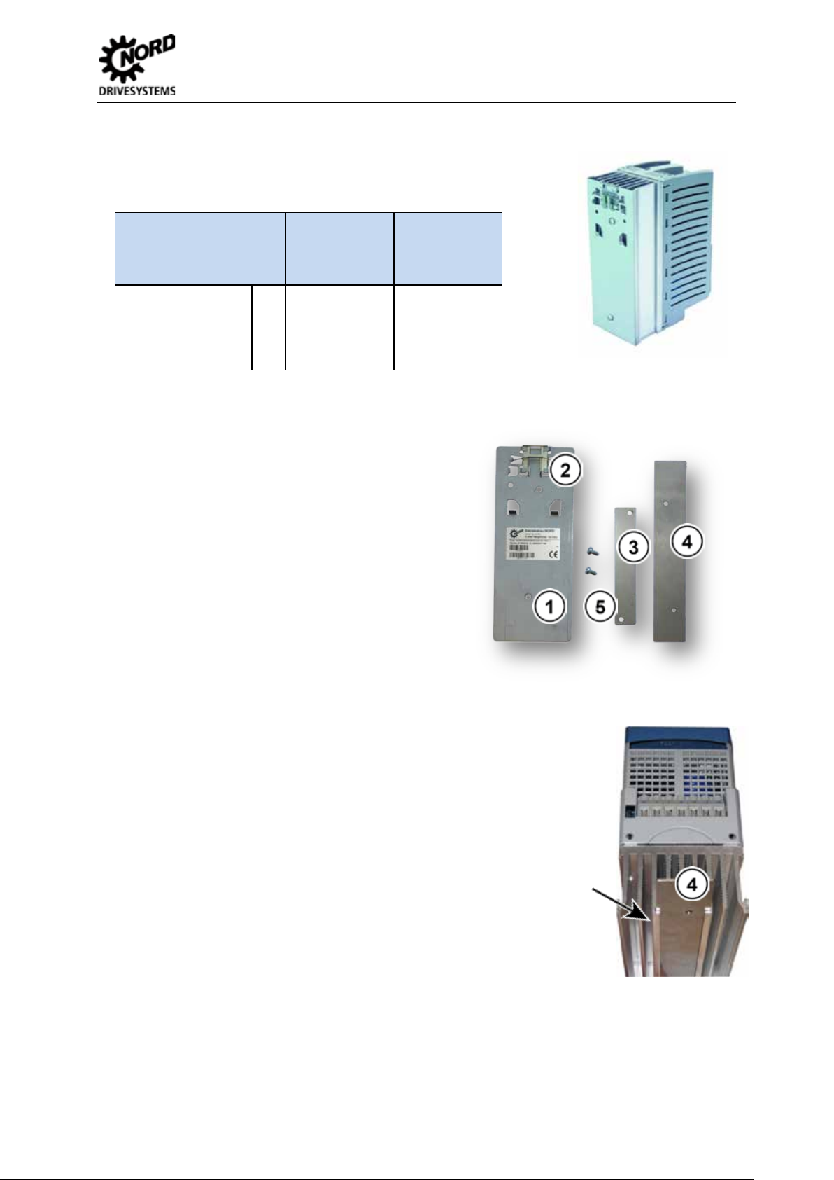
2.3 External heat sink kit
External heat sink technology is an optional supplement for ColdPlate
devices. This is use d if an external cooling system is provided, but no
liquid-cooled m ounting plate is available. A cooling element is mounted
on the ColdPlate device, which passes through an opening in the rear
panel of the control cabinet into the exterior air-cooled environment.
Convection takes place ou tside of the control cabinet, which results in
the same advantages as with ColdPlate technology.
Type
type
External heat
Size
sink kit
Part. No.
SK 5xxE-250- …-CP
SK 5xxE-750- …-CP
SK 5xxE-111- …-CP
SK 5xxE-221- …-CP
Scope of delivery
Dimensions
Type
sink kit
1
2
1=
Heat sink
2=
Gasket
3=
Heat-conducting paste
4=
Cylindrical-head screws wit h
Heat sink dimensions
[mm]
HK BK TK
SK TH1-1
SK TH1-2
Weight
Heat sink
Approx. [kg]
275999050
275999060
BK
TK
SK TH1-1 157 70 100 1.5
SK TH1-2 200 70 110 1.7
BU 0500 GB-1013 25
HK
Page 26

SK 500E – Users Manual for Frequency Inverters
Assembly
For installation, a hole with the size of the heat sink must be made in the w all of the control cabinet
(note the load bearing capacity).
1. App l y heat-conducting paste to the ColdPlate of the
SK 5xxE;
2. firmly fasten the heat sink to the ColdPlate with the
4 enclosed screws;
3. remove any heat conducting paste which exudes;
4. Place the seal between the frequency inverter and
the wall of the control cabinet (inside of the control
cabinet);
5. Insert the frequency inverter and guide the external
heat sink out of the control cabinet through the hole
in the wall of the control cabinet;
6. Fasten the frequency inverter to the wall of the
control cabinet though all of the 6 or 8 holes in the
ColdPlate.
Information
With correct installation, the control cabinet achieves IP54 from the outside at the point of installation.
Protection class IP54
Pos: 34 /Anl eitungen/El ektronik/FU und Start er/2. Mont age und Inst allation/2. 4 Hutschien enmontages et SK DRK1- ... [BU 0500] @ 0\mod_1325861903944_388.docx @ 5802 @ 255 @ 1
26 BU 0500 GB-1013
Page 27
2 Assembly and installation
ize 1 or 2
Frequency inverter
on rail. To
2.4 Snap-on mounting r ail kit SK DRK1-…
The snap-on mounting rail set SK DRK1-1 enables s
frequency inverters to be m ounted on a sta ndard T S35 (EN 50022)
mounting rail.
Type
type
Snap-on rail
Size
mounting kit
Part. No.
SK 5xxE-250- …
SK 5xxE-750- …
SK 5xxE-111- …
SK 5xxE-221- …
Scope of delivery
1=
2=
3=
4=
5=
SK DRK1-1
1
2
SK DRK1-2
275999030
275999040
Adapter for snap-on rail mounting
Clamp
Spacer
Fastening plate
Screws(2x)
Assembly
1. Push the fastening plate (4) into the guide on the heat sink (arrow);
2. place the spacer plate (3) on the fastening plate (4);
3. connect the snap-on rail mounting adapter (1) and the components
(3) + (4) with screws (5).
During assembly, take care that the stirrup (2) points upwards (mains
connection side of the inverter).
Then the inverter can be clipped directly onto the snaprelease the frequency inverter, the stirrup (2) must be pulled a few
millimetres out of the snap-on rail.
Pos: 35 /Anl eitungen/ Elektronik/F U und Start er/2. Mont age und Install ation/2.5 EMV- Kit [SK5xxE] @ 0\mod_1325861952008_388.docx @ 5825 @ 2 @ 1
BU 0500 GB-1013 27
Page 28

SK 500E – Users Manual for Frequency Inverters
b
Similar to illustration
Part No. 275999061
Note
strain relief (e.g. for the connection cables of a bus system)
2.5 EMC Kit
For optimum EMC-compliant wiring, the optional EMC Kit must be used. This includes a shield
bracket, two hamm er clips, two fasten ing screws an d a pre-assembled PE cable. T he PE cable mus t
be connected to the appropriate screw on the shielding bracket and to the PE terminal of the
frequency inverter. The connection of further PE connections to the shield bracket is possible with
additional ring cable lugs (SK EMC 2-1 and 2-2).
The EMC Kit provides th e pos sibi li t y of attaching the screening of the motor cable to a larg e s urf ac e of
the frequency inverter (interference source). If necessary, a screened brake resistor cable can be
attached with the second hammer clip.
The screening angle is attached to the two housing screws on the lower edge (below the U-V-W
terminals). The m otor cable screening is earthed to a large area of the s creening angle by means of
the hammer clip.
Fig. 4 EMC Kit SK EMC2-x
Device type Size EMC Kit Dimension "b"
SK 5xxE-250- … SK 5xxE-750- Size 1
SK 5xxE-111- … SK 5xxE-221- Size 2
SK 5xxE-301- … SK 5xxE-401- Size 3
SK 5xxE-551-340- … SK 5xxE-751- 340- Size 4
SK 5xxE-551-323- … SK 5xxE-751- 323-
SK 5xxE-112-340- … SK 5xxE-152- 340SK 5xxE-112-323-
SK 5xxE-182-340- … SK 5xxE-222- 340SK 5xxE-152-323- … SK 5xxE-182- 323-
SK 5xxE-302-340- … SK 5xxE-372- 340-
Size 5
Size 6
Size 7
SK 5xxE-452-340- … SK 5xxE-902- 340- Size 8/9
SK EMC 2-1
Part No. 275999011
SK EMC 2-2
Part No. 275999021
SK EMC 2-3
Part No. 275999031
SK EMC 2-4
Part No. 275999041
SK EMC 2-5
Part No. 275999051
SK EMC 2-6
42 mm
42 mm
52 mm
57 mm
57 mm
100 mm
Table 4: EMC Kit SK EMC2-x
The EMC Kit cannot be combined with ...-CP (ColdPlate) devices. Any cable screening must be earthed to a large
area of the mounting surface.
Alternatively, the EMC Kit can be simply used as a
(note the bending radii!).
Pos: 36 /Anl eitungen/ Elektronik/F U und Start er/2. Mont age und Ins tallation/2. 6 Bremswi derstand (B W) [BU 0500] @ 0\mod_1325862128510_388 .docx @ 5848 @ 2 @ 1
28 BU 0500 GB-1013
Page 29

2 Assembly and installation
CAUTION
should be checked with suitable measuring equipment. In addition, keep sufficient distance from adjacent
),inordertoi
SK BR4-...
Size 1 SK BR4-...
Size 2
SK BR2-... Size 3 SK BR2-... Size 4 and above
2.6 Brake resistor (BR)
The heat sink and all other metal components can heat up to temperatures above 70°C.
Touching such components may cause local burns to the affected parts of the body (hands, fingers, etc.).
To prevent such injuries, allow sufficient time for cooling down before starting work - the surface temperature
components during installation, or install protection against contact.
Danger of burns
During dynamic brak ing (frequency reduc tion) of a three-phase motor, electrica l energy is returne d to
the inverter. An external br ake resistor can be used in order to prevent the FI from being shut down
due to overvoltage. W ith this, the int egrated brake c hopper (electr onic s witch) pul ses the interm ediate
circuit voltage (switching wave approx. 420 V/775 V(/825 V) DC, according to the mains voltage)
(115 V, 230 V/400 V(/500 V)) to the brake resistor. Here the excess energy is converted into heat.
For inverter powers up to 7.5 kW (230 V: up to 4.0 kW) a standard bottom-mounted resistor
(SK BR4-..., IP40) ca n be u s ed. T his can additionally be equip ped wit h a n opt io na l temperature switch
(bi-metal, switching po int 1 00 ℃
is enclosed. The resistor and the temperature switch are connected by means of flexible stranded
conductors. Approval: UL, cUL
Note: Brake resistors cannot be directly mounted below …-CP (ColdPlate) devices.
For frequency inverters above 3kW chassis resistors (SK BR2-..., IP20) are also available. These
must be mounted i n the co ntrol c abinet, close to th e fr equenc y invert er. T here is a tem perature switch
on the braking resistor to provide protection against overload. Connection of the resistor and the
temperature switch is by means of screw terminals. Approval: UL, cUL
Fig. 5: Top: bottom-mounted brake resistor SK BR4- Bottom: chassis brake resistor SK BR2-...
Pos: 37 /Anl eitungen/ Elektronik/F U und Start er/2. Mont age und Ins tallation/2. 6.1 Elektr ische Date n BW [BU 05 00 ] @ 0\ mod_1325862333353_388.docx @ 5871 @ 3 @ 1
BU 0500 GB-1013 29
Page 30

SK 500E – Users Manual for Frequency Inverters
SK 5xxE-250-112-O …
SK 5xxE-370-112-O
SK 5xxE-550-112-O …
SK 5xxE-750-112-O
SK 5xxE-370-323-A
SK 5xxE-550-323-A …
SK 5xxE-750-323-A
SK 5xxE-111-323-A …
SK 5xxE-221-323-A
2 x 2.5mm
2
L = 0.5m
SK 5xxE-401-323-A
SK 5xxE-551-323-A …
SK 5xxE-751-323-A
SK BR2- 12/1500-C
Part No. 278282015
SK 5xxE-152-323-A …
SK 5xxE-182-323-A …
SK 5xxE-550-340-A …
SK 5xxE-750-340-A
SK 5xxE-111-340-A …
SK 5xxE-221-340-A
SK 5xxE-401-340-A
SK 5xxE-751-340-A
SK 5xxE-301-340-A …
SK 5xxE-401-340-A
SK 5xxE-551-340-A …
SK 5xxE-751-340-A
SK 5xxE-112-340-A …
SK 5xxE-152-340-A
SK 5xxE-222-340-A
SK 5xxE-372-340-A
SK 5xxE-452-340-A …
SK 5xxE-552-340-A
SK 5xxE-752-340-A …
SK 5xxE-902-340-A
2.6.1 Electrical data, brake resistor
Connecting
cable /
terminals
Inverter ID Resistor type Resistance
Continuous
rating
Pulse
energy*
SK 5xxE-250-323-A …
SK 5xxE-301-323-A …
SK 5xxE-401-323-A
SK 5xxE-301-323-A …
SK 5xxE-112-323-A
SK 5xxE-301-340-A …
SK 5xxE-551-340-A …
SK 5xxE-182-340-A …
SK 5xxE-302-340-A …
SK BR4-240/100
Part No. 275991110
SK BR4-150/100
Part No. 275991115
SK BR4-240/100
Part No. 275991110
SK BR4-150/100
Part No. 275991115
SK BR4- 75/200
Part No. 275991120
SK BR4- 35/400
Part No. 275991140
SK BR2- 35/400-C
Part No. 278282045
SK BR2- 22/600-C
Part No. 278282065
SK BR2- 9/2200-C
Part No. 278282122
SK BR4-400/100
Part No. 275991210
SK BR4-220/200
Part No. 275991220
SK BR4-100/400
Part No. 275991240
SK BR4-60/600
Part No. 275991260
SK BR2-100/400-C
Part No. 278282040
SK BR2- 60/600-C
Part No. 278282060
SK BR2- 30/1500-C
Part No. 278282150
SK BR2- 22/2200-C
Part No. 278282220
SK BR2- 12/4000-C
Part No. 278282400
SK BR2- 8/6000-C
Part No. 278282600
SK BR2- 6/7500-C
Part No. 278282750
240 Ω
150 Ω
240 Ω
150 Ω
75 Ω
35 Ω
35 Ω
22 Ω
12 Ω
9 Ω
400 Ω
220 Ω
100 Ω
60 Ω
100 Ω
60 Ω
30 Ω
22 Ω
12 Ω
8 Ω
6 Ω
100 W 1.0 kWs
2 x 1.9mm
AWG 14/19
100 W 1.0 kWs
L = 0.5m
100 W 1.0 kWs
2 x 1.9mm
100 W 1.0 kWs
AWG 14/19
L = 0.5m
200 W 3.0 kWs
400 W 6.0 kWs
AWG 14/19
400 W 6.0 kWs 2 x 10mm
600 W 7.5 kWs 2 x 10mm
1500 W 20 kWs 2 x 10mm
2200 W 28 kWs 2 x 10mm
100 W 1.0 kWs
2 x 1.9mm
AWG 14/19
200 W 3.0 kWs
400 W 6.0 kWs
L = 0.5m
2 x 2.5mm
AWG 14/19
600 W 12.0 kWs
L = 0.5m
400 W 6.0 kWs
2 x 10mm
600 W 7.5 kWs
1500 W 20 kWs
2200 W 28 kWs
2 x 10mm
4000 W 52 kWs
6000 W 78 kWs
7500 W 104 kWs 2 x 25mm
*) Maximum once for 1.2s within 120s
2
2
2
2
2
2
2
2
2
2
2
Table 5: Electrical data for brake resistor SK BR2-… and SK BR4-…
The chassis brak e resistors (SK BR2-…) listed ab ove are equipped with a temperature switch at the
factory. An optional temperature switch is available for the bottom-mounted brake resistor
(SK BR4-…). In or der to use the signal from the temperature switch it m ust be connected to a free
digital input of the frequenc y inverter an d, f or example, parameterised with the fun c tion "Vo ltag e bl ock"
or "Fast stop".
30 BU 0500 GB-1013
Page 31

2 Assembly and installation
℃
L = 0.5m
250Vac
30Vdc
10A
5A
∅
SK BR4- 75/200
SK BR4-... Size 1 SK BR4-... Size 2
B A C
D
NORDAC SK 5xxE
Optional temperature switch
B A C
D
NORDAC SK 5xxE
Bi-metal temperature switch
for... Part No.
SK BR4-... 275991200 IP40 250Vac
SK BR2-... integrated IP00
Table 6: Brake resistor temperature switch data
Pos: 38 /Anl eitungen/ Elektronik/F U und Start er/2. Mont age und Ins tallation/2. 6.2 Abmess ungen Unt erbau- BW SK BR4 [BU 05 0 0] @ 0\ mod_132586248 5335_388.docx @ 5894 @ 3 @ 1
Protection
class
Voltage Current
2.5A with cosϕ=1
1.6A with cosϕ=0.6
125Vac
15A
2.6.2 Dimensions of bottom-mounted BR SK BR4
Resistor type Size A B C
SK BR4-240/100
SK BR4-150/100
SK BR4-400/100
SK BR4-220/200
SK BR4-35/400
SK BR4-100/400
Size 1 230 88 175 220 5.5
Size 2 270 88 175 260 5.5
Size 3 285 98 239 275 5.5
Nominal
switching
Dimensions
temperature
100
Width +10mm
(one side)
180°C ± 5K Internal
Fixing dimensions
D
Connecting
cable /
terminals
Flexible
strand 2 x
0.8mm
2
AWG 18/19
terminals
2 x 4mm
2
SK BR4-60/600
C = Installation depth of the frequency inverter + bottom-mounted brake resistor. All dimensions in mm
Table 7: Dimensions of bottom-mounted brake resistor SK BR4-...
Size 4 330 98 239 320 5.5
BU 0500 GB-1013 31
Page 32

SK 500E – Users Manual for Frequency Inverters
SK BR4-... Size 3
SK BR4-... Size 4
Type plate
Temperature switch optional
please order separately
For fitting by the customer
Temperature switch optional
please order separately
For fitting by the customer
Type plate
Separate data sheets are available for bott om-mounted brak e resistors SK BR4 abo ve size 3. These
can be downloaded at www.nord.com
.
Inverter ID Brake resistor type Part No. Data sheet
SK 5xxE-301-323-A … -401-323-A
SK 5xxE-301-340-A … -401-340-A
SK 5xxE-551-340-A … -751-340-A
Pos: 39 /Anl eitungen/ Elektronik/F U und Start er/2. Mont age und Ins tallation/2. 6.3 Abmess ungen Chas sis-BW SK BR2 [BU 0 50 0, u.A.] @ 0\mod_1325862658505_388.docx @ 5917 @ 3 @ 1
SK BR4-35/400
SK BR4-100/400
SK BR4-60/600
275991140 TI014 275991140
275991240 TI014 275991240
275991260 TI014 275991260
32 BU 0500 GB-1013
Page 33

2 Assembly and installation
∅
SK BR2-100/400-C
SK BR2- 35/400-C
SK BR2- 60/600-C
SK BR2- 22/600-C
SK BR2- 30/1500-C
SK BR2- 12/1500-C
SK BR2- 22/2200-C
SK BR2- 9/2200-C
SK BR2- 12/4000-C
560
270
240
530
240
6.5
SK BR2- 8/6000-C
470
600
300
440
2x220
6.5
SK BR2- 6/7500-C
570
600
300
540
2x220
6.5
All dimensions in mm
SK BR2-... FI size 3 and above
(Schematic diagram, model varies
according to power)
B
A
E
D
C
2.6.3 Dimensions, brake resistor chassis SK BR2
Resistor type A B C
170 100 240 150 90 4.3
350 92 120 325 78 6.5
560 185 120 530 150 6.5
460 270 120 430 240 6.5
Fixing dimensions
D E
Table 8: Dimensions of chassis brake resistor SK BR2-...
Pos: 40 /Anl eitungen/ Elektronik/F U und Start er/2. Mont age und Ins tallation/2. 7 Netzdros sel SK CI1 [BU 0500, u.A.] @ 0\mod_1325862740832_388.docx @ 5940 @ 2 @ 1
BU 0500 GB-1013 33
Page 34

SK 500E – Users Manual for Frequency Inverters
V at
The choke used
must therefore be installed in a control
oke is
being used, in order to avoid possible
Continuous
SK CI1-230/20-C
All dimensions in [mm]
[mm2]
SK CI1-480/6-C
SK CI1-480/11-C
Part. No.: 276993011
SK CI1-480/20-C
SK CI1-480/40-C
SK CI1-480/70-C
Part. No.: 276993070
SK CI1-480/100-C
All dimensions in [mm]
[mm2]
D
L2
L1
W1
B2
L1
L2
L22
L12
L3
L32
Similar to
illustration
2.7 Mains choke SK CI1
To reduce input side current harmonics,
additional inductivity can be installed into
the line supply to the inverter.
These chokes ar e specif ied f or a m aximum
supply voltage of 230 V or 480
50/60 Hz.
All chokes have a protection class
corresponding to IP00.
cabinet.
For frequency inverters w ith an output of
45 kW or more, a line ch
recommended where several devices are
adverse effects of one device on another.
In addition, the charging currents (mains voltage fluctuations) are significantly reduced.
Input choke 1 x 220 - 240 V
Inverter ID
NORD
SK 500E
0.25 ... 0.75hp
1.1 ... 2.2 kW
Type
SK CI1-230/8-C
Part. No.: 278999030
Part. No.: 278999040
current
8 A 2 x 1.0 mH 78 65 89 56 40 M4 4
20 A 2 x 0.4 mH 96 90 106 84 65 M6 10
Table 9: Mains choke data for SK CI1-..., 1~ 240 V
Inductance
L1 W1 D
Detail: Mounting
L2 B2
Inverter ID
NORD
SK 500E
0.25 ... 0.75hp
1.1 ... 1.5 kW
Input choke 3 x 200 - 240 V
Type
Part. No.: 276993006
Continuous
current
Inductance
6 A 3 x 4.88 mH 96 60 117 71 45 M4 4
11 A 3 x 2.93 mH 120 85 140 105 70 M4 4
L1 W1 D
Detail: Mounting
L2 B2
Connection
Installation
Connection
Installation
2.2 … 3.0 kW
4.0 … 7.5 kW
Part. No.: 276993020
Part. No.: 276993040
11 … 15 kW
18 kW
Part. No.: 276993100
Table 10: Mains choke data for SK CI1-..., 3~ 240 V
34 BU 0500 GB-1013
20 A 3 x 1.47 mH 155 110 177 135 95 M5 10
40 A 3 x 0.73 mH 155 115 172 135 95 M5 10
70 A 3 x 0.47 mH 185 122 220 170 77 M6 35
100 A 3 x 0.29 mH 240 148 263 180 122 M6 35
Page 35

2 Assembly and installation
Continuous
Installation
SK CI1-480/6-C
Part. No.: 276993006
SK CI1-480/11-C
Part. No.: 276993011
SK CI1-480/20-C
Part. No.: 276993020
SK CI1-480/40-C
Part. No.: 276993040
SK CI1-480/70-C
SK CI1-480/100-C
SK CI1-480/160-C
Part. No.: 276993160
SK CI1-480/280-C
All dimensions in [mm]
[mm2]
Input choke 3 x 380 - 480 V
Inverter ID
NORD
SK 500E
0.55 ... 2.2 kW
3.0 ... 4.0 kW
5.5 ... 7.5 kW
11 ... 15 kW
18 ... 30hp
37 … 45 kW
55 … 75 kW
90 kW
* Bolt for copper rail
Table 11: Mains choke data for SK CI1-..., 3~ 480 V
Pos: 41 /Anl eitungen/ Elektronik/F U und Start er/2. Mont age und Install ation/2.8 A usg a ngsdrossel SK CO 1 [BU 05 00, u.A.] @ 0\mod_1325863040983_388.do cx @ 5963 @ 2 @ 1
Type
Part. No.: 276993070
Part. No.: 276993100
Part. No.: 276993280
current
Inductance
6 A 3 x 4.88 mH 96 60 117 71 45 M4 4
11 A 3 x 2.93 mH 120 85 140 105 70 M4 4
20 A 3 x 1.47 mH 155 110 177 135 95 M5 10
40 A 3 x 0.73 mH 155 115 172 135 95 M5 10
70 A 3 x 0.47 mH 185 122 220 170 77 M6 35
100 A 3 x 0.29 mH 240 148 263 180 122 M6 35
160 A 3 x 0.18 mH 352 140 268 240 105 M8 M8*
280 A 3 x 0.10 mH 352 169 268 240 133 M10 M16*
Detail: Mounting
L1 W1 D
L2 B2
Connection
BU 0500 GB-1013 35
Page 36

SK 500E – Users Manual for Frequency Inverters
To reduce interference signals from the
capacitance in long motor cables, an
additional output choke can be installed
or a
V at
0.25 … 0.75
kW
SK CI1-460/9-C
SK CI1-460/17-C
SK CI1-460/33-C
SK CI1-460/90-C
Part. No.: 276996090
3 x 0.22 mH
All dimensions in [mm]
[mm2]
D
L2
L1
W1
B2
U V V2
U2 W W3
Similar to
illustration
2.8 Output choke SK CO1
motor cable or to compensate for cable
into the inverter output.
During installation tak e care that the pulse
frequency of the frequency inverter is set
to 3 - 6 kHz (P504 = 3 - 6).
These chokes are specified f
maximum supply voltage of 480
0 - 100 Hz.
An output choke s hould be fitted f or cable le ngths over 100 m/30 m (unshie lded/shielded). All chok es
have a protection class corresponding to IP00. The choke used must therefore be installed in a control
cabinet.
Output choke 3 x200 – 240 V
Inverter ID
NORD
SK 5xxE
1.1 ... 1.5 kW
2.2 ... 4.0 kW
5.5 ... 7.5 kW
11 … 15 kW
Type
SK CI1-460/4-C
Part. No.: 276996004
Part. No.: 276996009
Part. No.: 276996017
Part. No.: 276996033
SK CI1-480/60-C
Part. No.: 276992060
18 kW
Table 12: Output choke data for SK CO1-..., 3~ 240 V
Detail: Mounting
Continuous
current
Inductance
L1 W1 D
L2 B2
4 A 3 x 3.5 mH 120 104 140 84 75 M6 4
9 A 3 x 2.5 mH 155 110 160 130 71.5 M6 4
17 A 3 x 1.2 mH 185 102 201 170 57.5 M6 10
33 A 3 x 0.6 mH 185 122 201 170 77.5 M6 10
60 A 3 x 0.33 mH 185 112 210 170 67 M8 16
90 A
352 144 325 224 94 M10 35
Connection
36 BU 0500 GB-1013
Page 37

2 Assembly and installation
Installation
SK CI1-460/4-C
Part. No.: 276996004
SK CI1-460/9-C
Part. No.: 276996009
SK CI1-460/17-C
Part. No.: 276996017
SK CI1-460/33-C
Part. No.: 276996033
SK CI1-480/60-C
55 … 75 kW
SK CI1-460/170-C
Part. No.: 276996170
90 kW
SK CI1-460/240-C
Part. No.: 276996170
All dimensions in [mm]
[mm2]
Inverter ID
NORD
SK 5xxE
0.55 ... 1.5 kW
2.2 ... 3.0 kW
4.0 ... 7.5 kW
11 ... 15 kW
18 ... 30hp
37 … 45 kW
Output choke 3 x 380 – 480 V
Type
Part. No.: 276992060
SK CI1-460/90-C
Part. No.: 276996090
Continuous
current
Inductance
L1 W1 D
4 A 3 x 3.5 mH 120 104 140 84 75 M6 4
9 A 3 x 2.5 mH 155 110 160 130 71.5 M6 4
17 A 3 x 1.2 mH 185 102 201 170 57.5 M6 10
33 A 3 x 0.6 mH 185 122 201 170 77.5 M6 10
60 A 3 x 0.33 mH 185 112 210 170 67 M8 16
90 A 3 x 0.22 mH 352 144 325 224 94 M10 35
Detail: Mounting
L2 B2
170 A 3 x 0.13 mH 412 200 320 264 125 M10 M12*
240 A 3 x 0.07 mH 412 225 320 388 145 M10 M16*
* Bolt for copper rail
Table 13: Output choke data for SK CO1-..., 3~ 480 V
Pos: 42 /Anl eitungen/ Elektronik/F U und Start er/2. Mont age und Ins tallation/2. 9 Netzfilt er [BU 0500 ] @ 0\mod_1325863166231_388.docx @ 5986 @ 2 @ 1
2.9 Line filter
An additional external line filter can be installed into the line supply of the frequency inverter to
maintain the increased noise suppression level (class B as per EN 55011).
Pos: 43 /Anl eitungen/ Elektronik/F U und Start er/2. Mont age und Ins tallation/2. 9 Netzfilt er -Teil 1 - Netzfilter SK NHD [BU 0500] @ 1\mod_1331135215479_388.docx @ 17490 @ 5 @ 1
Mains filter SK NHD (up to size 4)
Connection
SK NHD type mains filters are so-called bottom-mounted combination filters with integrated mains
choke. The mains filter is only intended for three-phase operation.
This provides a com pact unit to im prove the le vel of r adio inter fer ence suppr essi on, whic h can als o be
mounted underneath the frequency inverter if there is a shortage of space.
For further information abo ut the overv oltage filter , please ref er to the relevant da ta sheet. Thes e data
sheets can be downloaded from www.nord.com
.
Inverter ID Filter type Part No. Data sheet
SK 5xxE-250-323-A … -750-323-A
SK 5xxE-111-323-A … -221-323-A
SK 5xxE-301-323-A … -401-323-A
SK 5xxE-550-340-A … -750-340-A
SK 5xxE-111-340-A … -221-340-A
SK 5xxE-301-340-A … -401-340-A
SK 5xxE-551-340-A … -751-340-A
Table 14: Mains filter NHD-...
Pos: 44 /Anl eitungen/ Elektronik/F U und Start er/2. Mont age und Ins tallation/2. 9 Netzfilt er -Teil 2 - Netzfil ter SK LF2 [BU 0 500] @ 1\mod_1331135342246_388.docx @ 17514 @ 5 @ 1
SK NHD-480/6-F
SK NHD-480/10-F
SK NHD-480/16-F
SK NHD-480/3-F
SK NHD-480/6-F
SK NHD-480/10-F
SK NHD-480/16-F
278273006 TI030 278273006
278273010 TI030 278273010
278273016 TI030 278273016
278273003 TI030 278273003
278273006 TI030 278273006
278273010 TI030 278273010
278273016 TI030 278273016
BU 0500 GB-1013 37
Page 38

SK 500E – Users Manual for Frequency Inverters
SK 5xxE-551-323-A
SK 5xxE-751-323-A
SK 5xxE-112-323-A
SK 5xxE-182-323-A
SK 5xxE-152-340-A
SK 5xxE-182-340-A
SK 5xxE-222-340-A
SK 5xxE-372-340-A
SK 5xxE-552-340-A
SK 5xxE-902-340-A
All dimensions in mm
mm
2
L1
L2
L3
L3'
L2'
L1'
L2
L1
B2
T
Netz / LINE
Gerät / LOAD
B1
Mains filter SK LF2 (size 5 - 6)
SK LF2 type mains filter s are mains filters which can be bott om mounted, and their dimensions are
matched to those of the relevant frequency inverter. This enables space-saving installation.
Inverter ID Filter type Part No.
SK 5xxE-551-323-A … -751-323-A
SK 5xxE-112-323-A
SK 5xxE-112-340-A … -152-340-A
SK 5xxE-182-340-A … -222-340-A
Table 15: Mains filter LF2-...
Pos: 45 /Anl eitungen/ Elektronik/F U und Start er/2. Mont age und Ins tallation/2. 9 Netzfilt er -Teil 3 - Netz fi l ter SK HLD [BU 0500] @ 1\ mod_13311353 94656_388.docx @ 17538 @ 5 @ 1
SK LF2-480/45-F
SK LF2-480/66-F
SK LF2-480/45-F
SK LF2-480/66-F
278273045 TI030 278273045
278273066 TI030 278273066
278273045 TI030 278273045
278273066 TI030 278273066
Mains filter SK HLD (above size 5)
In addition, a chassis m ains filter is availab le for inverters of size V and above. This
enables Class Br adio inter ferenc e sup press ion up to a m aximum motor cable len gth
of 25 m.
When connecting the line filter, comply with "W iring guidelines" Section 2.10.1 and
"EMC" Section 8.3. In partic ular, care must be taken that the pulse frequenc y is set
to the default value (P504 = 6k Hz). The line filter should be placed as close to the
side of the inverter as possible.
The connection is b y means of screw connections o n the upper (mains) and lower
(inverter) ends of the filter
Data sheet
Inverter ID
SK 5xxE-152-323-A…
SK 5xxE-112-340-A…
SK 5xxE-302-340-A…
SK 5xxE-452-340-A…
SK 5xxE-752-340-A…
Table 16: Mains filter HLD-...
Pos: 46 /Anl eitungen/ Elektronik/F U und Start er/2. Mont age und Ins tallation/2. 9 Netzfilt er -Teil 4 - Spannungsbegrenzungsfilter SK CIF [BU 0500] @ 0\mod_1325863390898_388.docx @ 6009 @ 5 @ 1
Filter type
[-V/A]
SK HLD 110-500/30
SK HLD 110-500/42
SK HLD 110-500/75
SK HLD 110-500/100
SK HLD 110-500/42
SK HLD 110-500/55
SK HLD 110-500/75
SK HLD 110-500/130
SK HLD 110-500/180
SK HLD 110-500/250
Detail: Mounting Connection
L1 W1 D
L2 B2
cross-
section
270 55 95 255 30 10
310 55 95 295 30 10
270 85 135 255 60 35
270 95 150 255 65 50
310 55 95 295 30 10
250 85 95 235 60 16
270 85 135 255 60 35
270 95 150 255 65 50
380 130 181 365 102 95
450 155 220 435 125 150
38 BU 0500 GB-1013
Page 39

2 Assembly and installation
Voltage limitation filter SK CIF
Up to and including size 6 , the use of a sui table overvolta ge filter is m andatory (see a lso Section 1.5)
in order to comply with cU L requirements. For f urther information about the o vervoltage filter, pl ease
refer to the relevant data sheet. These data sheets can be downloaded from www.nord.com
.
Inverter ID Filter type Part No.
SK 5xxE-250-323-A … -301-323-A*
SK 5xxE-401-323-A … -112-323-A*
SK 5xxE-550-340-A … -751-340-A
SK 5xxE-112-340-A … -222-340-A
* (only with suitable mains choke)
Table 17: Mains filter SK CIF-...
Pos: 47 /Anl eitungen/ Elektronik/F U und Start er/2. Mont age und Ins tallation/2. 10 Elektr ischer Ansc hluss [BU 0 500] @ 0\mod_1325863603644_388.docx @ 6055 @ 2 @ 1
SK CIF-323-20
SK CIF-323-40
SK CIF-340-30
SK CIF-340-60
Data sheet
276997070 TI030 276997070
276997071 TI030 276997071
276997080 TI030 276997080
276997081 TI030 276997081
BU 0500 GB-1013 39
Page 40

SK 500E – Users Manual for Frequency Inverters
Safe operation of the devices presupposes that qualified personnel mount and operate it in compliance with the
afety regulations for work on high voltage systems (e.g.
VDE) must be complied with as must the regulations concerning correct use of tools and the use of personal
1 =
Mains connection
L1, L2/N, L3, PE
X1
2 =
Motor connection
U, V, W, PE
X2
3 =
multi-function relay
1 - 4
X3
4 =
Braking resistor
+B, -B
X2
5 =
DC - link circuit
-DC
X2
Above Size 8: + DC, - DC
6 =
Control terminals
IOs, GND, 24Vout, IG, DIP for AIN
à
X4, X5, X6, X7, X14
7 =
Technology unit
8 =
Link circuit choke
-DC, CP, PE
Above size 8:
2.10 Electrical connections
WARNING
THESE DEVICES MUST BE EARTHED.
instructions provided in these operat ing in struc t io ns.
In particular, the general and regional installation and s
protection equipment.
Dangerous voltages can be present at the motor connection terminals even when the inverter is switched off.
Always use insulated screwdrivers on these terminal fields.
Ensure that the input voltage source is not live before setting up or changing connections to the unit.
Make sure that the inverter and motor have the correct supply voltage set.
Note
Thermistor
As with other signal cables, thermistor cables must be laid separately from the motor cables
Depending on the size of the f requency inverter, the connection term inals for the supply cables and
the control cables ar e located in different positions. According to the configuration of the frequency
inverter, various terminals are not present.
Size 1 - 4 Size 5 - 7 Above size 8
40 BU 0500 GB-1013
Page 41

2 Assembly and installation
9 =
communication
CAN/CANopen; RS232/RS485
à
X9/X10; X11
10 =
Thermistor
T1/2 or TF+/-
X13
Up to size 4 (except SK 54xE): to DIN 5
11 =
Safe pulse block
86, 87, 88, 89
X8
12 =
Control voltage VI 24V
40, 44
X12
Except SK 5x0E and SK 511E
Size 1 - 4 Size 5 - 7 Above size 8
Pos: 48 /Anl eitungen/ Elektronik/F U und Start er/2. Mont age und Ins tallation/2. 10.1 Verdr ahtungsric htlinien [Al lg.] @ 0\mod_1325863475147_388.docx @ 6032 @ 3 @ 1
2.10.1 Wiring guidelines
The frequency inverters have been developed for use in an industrial environment. In this
environment, high le vels of electr omagnet ic interf erence can act on the freque ncy inver ter. In gener al,
correct installation ensures safe and problem-free operatio n. To meet the lim iting values of the EMC
directives, the following instructions should be complied with.
1. Ensure that all equipment in the control cabinet is securely earthed using short earthing cables
which have large cross-sections and are connecte d to a common ear thing point or earth ing bar. It
is especially important that each control unit which is connecte d to the electronic drive technol ogy
(e.g. an automatic de vice) has a short c able with a la rge cross-section, which is connected t o the
same earthing point as the dfrequency inverter itself. Flat cables (e.g. metal stirrups) are
preferable, as they have a lower impedance at high frequencies.
2. The bonding cable of the m otor c ontr o lled by the frequency inverter s hou ld b e connected directly to
the earthing terminal of the associated controller. The presence of a central earthing bar in the
control cabinet and the grouping together of a ll bonding conductors to this bar normally ensures
safe operation.
3. W here poss ible, shield ed cables should be us ed for contr ol circuits . The shie lding at th e cable end
should be caref ully sealed and it m ust be e nsured th at th e wires are not laid over longer distances
without shielding.
The shields of analog setpoint cables should only be earthed on one side on the device.
4. T he control cables sh ould be installe d as far as possible f rom power cables , using separate ca ble
ducts, etc. Where cables cross, an angle of 90° should be ensured as far as possible.
5. Ensure that the contactors in the cabinet are interference protected, either by RC circuits in the
case of AC contactors or by free-wheeling diodes for DC contactors, for which the interference
traps must be positioned on the contactor coils. Varistors for o ver-voltage limitation are also
effective. This inter ference suppression is partic ularl y impor tant when the c ontactors are contro lled
by the relay in the frequency inverter.
6. Shi elded or arm oured c ables s hould be use d for the load co nnections (m otor c able). The sh ielding
or armouring mus t be earthed at both ends. If possible, earthing should be made directly to t he
electrically conducting mounting plate of the control cabinet or the screening angle of the EMC Kit.
BU 0500 GB-1013 41
Page 42

SK 500E – Users Manual for Frequency Inverters
The control cables, mains cables and motor cables must be laid separately. Under no circumstances may they be
r high voltage insulations must not be used on cables that are connected to the motor
In addition, EMC-compliant wiring must be ensured. If required, an optional output choke can be
supplied
The safety regulations must be complied with under all circumstances when installing the
frequency inverter!
NOTICE
installed in a common conduit or installation duct, in order to prevent interference.
The test equipment fo
controller. Failure to comply with this will cause damage to the drive electronics.
Pos: 49 /Anl eitungen/ Elektronik/F U und Start er/2. Mont age und Ins tallation/2. 10.2 Anpassung an IT-Netze [BU 05 0 0] @ 1\ mod_1331196207398_388.docx @ 17782 @ 355 @ 1
Interference and damage
2.10.2 Adaptation to IT networks
As delivered, the dev ice is conf igured for operat ion in TN or TT net work s. Sim ple adaptat ions m ust be
made for operation in an It network. However, these adaptations also cause a deterioration in the
suppression of radio interference.
Up to and including s ize 7, the adaptat ion is made wit h jumpers. As del ivered, the jum pers are set in
the “normal position” . W ith this, the mains filter has its norm al eff ect and leak age current. Fr om si ze 8
and above there is a DIP switch element. According to the setting of the DIP switch, the f requency
inverter is configured for TN/TT network operation or for operation in an IT network (also refer to
Sections Fehler! Verweisquelle konnte nicht gefunden werden. and 0).
Frequency inverter Jumper A Jumper B Remarks Leakage current
Size 1 - 4 Position 1 Position 1 Operation in IT network Not applicable
Size 1 - 4 Position 3 Position 2 Large filtering effect < 30 mA
Size 1 - 4 Position 3 Position 3 Limited effect of filter
Size 5 - 6 Position 0 Position 1 Operation in IT network Not applicable
Size 5 - 6 Position 4 Position 2 Large filtering effect < 6 mA
Size 7 Position 0 Position 1 Operation in IT network Not applicable
Size 7 Position 4 Position 2 Large filtering effect < 6 mA
Size 8 - 9 OFF Operation in IT network < 30 mA
Size 8 - 9 ON Large filtering effect < 10 mA
DIP switch "EMC-Filter"
<< 30 mA
> 3.5 mA
Table 18: Integrated mains filter
Adaptation of sizes 1 - 7
NOTICE
Jumper positions which are not illustrated below must not be used, as these may cause the destruction of the
frequency inverter.
Jumper positions
42 BU 0500 GB-1013
Page 43

2 Assembly and installation
= Operation in IT network = Position 1
(reduced leakage current)
= normal position = Position 3
= Operation in IT network = Position 0
(reduced leakage current)
= normal position = Position 4
= Operation in IT network = Position 1
= normal position = Position 2
= reduced leakage current – Position 3
(The set pulse frequency (P504) only has a slight
influence on the leakage current.)
= Operation in IT network = Position 1
(reduced leakage current)
= normal position = Position 2
Geräte- Oberseite
Top side of device
Underside of the device
Underside of the device
Jumper “A” mains input
Size 1 - 4
Size 5 - 7
Jumper 'B' motor output
Size 1 - 4
Size 5 - 7
BU 0500 GB-1013 43
Page 44

SK 500E – Users Manual for Frequency Inverters
"OFF" position. The leakage current is reduced, with a
NOTICE
ssential to note the following summary of criteria for the setup of a DC supply or the coupling of the link
phase devices, care must be taken that the coupling to the same external
Adaptation above size 8
The adaptation to the IT network is carried out via the DIP
switch "EMC Filter" (1). As del ivered, this s witch is in the "ON"
position.
For operation in an IT network the switch must be s et to the
deterioration in the EMC com patibil ity.
Pos: 50 /Anl eitungen/ Elektronik/F U und Start er/2. Mont age und Ins tallation/2. 10.3 Gleic hspannung skopplung [BU 0500] @ 1 \mod_1331196183481_388.docx @ 17758 @ 3 @ 1
2.10.3 DC-coupling
Overload of link circuits
It is e
circuits of frequency inverters.
Errors in the link circuit coupling have especially negative effects on the charging circuits in the inverters or on the
life span of the link circuits - including their complete destruction.
In drive engineering, DC-coupling is advisable if m otors act as drivers and generators at the sam e
time in the system. Here, the energ y from the drive which is actin g as a generat or can be fed bac k to
the drive which is acti ng as a motor. T he advantages are lower energy consumption a nd the sparing
use of braking resistor s. In addition, t he e nerg y balance c an be m ade eve n m ore ef ficient with the us e
of a regenerative feed bac k unit or an inp ut/f eedb ac k unit. In general, in cas e of D C coupl in g, wh er ev er
possible, devices w ith the same power should be c onnected together. Further more, only operational
devices (whose link circuits are charged) must be coupled.
Connection
Size 1 … 7 +B, - DC
Above size 8: + DC, - DC
NOTICE
DC coupling for single phase devices
For direct current coupling of singleconductor is used. Otherwise the device may be destroyed.
For the 115V devices (SK 5xx-xxx-112-O), no DC coupling is possible.
44 BU 0500 GB-1013
Page 45

2 Assembly and installation
M
3~
PE U V W +B -B -DC
PE L3 L2 L1
L1 / L
L2 / N
L3 / PE
M
3~
PE U V W +B -B -DC
PE L3 L2 L1
Coupling if
FIs ready
Readiness
message from
all FIs
U1
U2
Fig. 6 Diagram of a DC-coupling
1 The link circuits of the individual frequency inverters must be protected with suitable fuses.
2 The frequency inverters only obtain their power supply via the link circuit. Electrical isolation is
carried out via the power circuit breakers which must be provided in the supplies to the devices.
3 CAUTION! Ensure that the coupling is only made after readiness is reported. Otherwise, there
is a danger that all the frequency inverters will be charged by a single one.
4 Ensure that the coupling is disconnected as soon as one of the devices is no longer ready for
operation.
5 For a high availability a braking resistor must be used. If different sizes of frequency inverters
are used, the braking resistor must be connected to the larger of the two frequency inverters.
6 If devices with the same rating (identical type) are coupled, and the same mains impedances
are in effect (identical lengths of cable to the mains rail), the frequency inverters may be
operated without mains chokes. Otherwise a mains choke must be installed in the mains cable
of each frequency inverter.
BU 0500 GB-1013 45
Page 46

SK 500E – Users Manual for Frequency Inverters
PE U V W +B -B -DC
PE L3 L2 L1
L1 / L
L2 / N
L3 / PE
M
3~
PE U V W +B
-B -DC
PE L3 L2 L1
M
3~
PE L3 L2 L1
Input/feedback
unit
For information on
connection and
protection, as well as the
necessary accessories,
please consult the
manufacturer of the
input/feedback unit.
+ -
Fig. 7 Diagram of a DC coupling with an input/feedback unit
The following points must be taken into consideration in association with a DC supply:
Pos: 51 /Anl eitungen/ El e k tr o ni k/FU und Start er / 2. Montage und I ns t al l ation/2.1 0. 4 El e ktrischer Ansc hluss Leist u ng s t ei l [B U 05 00] @ 0\mod_1325863684752_388.docx @ 6078 @ 3 @ 1
46 BU 0500 GB-1013
1 Use a connecting cable which is as short as possible between the DC bus and the equipment to
be connected. The connection and protection of the devices in the DC circuit must be carried
out for cable protection and the maximum cross-section of the device.
2 The link circuits of the individual frequency inverters must be protected with suitable fuses.
3 The frequency inverters only obtain their supply via the link circuit. Electrical isolation is carried
out via the power circuit breakers which must be provided in the supplies to the devices.
4 For frequency inverters above size 8, a DC supply is only permissible with an external charging
device.
Page 47

2 Assembly and installation
2.10.4 Electrical connections, power unit
Before connecting the frequency inverter, the following must be observed:
1. Ensure that the mains supply provides the correct voltage and is suitable for the current required.
2. Ens ure that sui table circuit br eak ers with t he s pecified nom inal cur rent range are instal led be tw een
the voltage source and the inverter.
3. Connect the mains voltage directly to the mains terminals L1-L2/N-L3-PE (for each device)
4. A four-core cable must be used to connect the motor. The cable is connected to the motor
terminals PE-U-V-W.
5. If screened m otor cables (r ecom m ended) are us ed, the cable s cree ning m us t also be con nected to
a large area of the m etallic screening angle of the EMC Kit, however, at least to the electricall y
conducting mounting surface of the control cabinet.
6. Above size 8, the cable lugs which are included in the scope of delivery must be used. After
crimping, these must be insulated with shrink hose.
Note
The use of shielded cables is essential in order to maintain the specified radio interference suppression level.
If certain wire end sleeves are used, the maximum cross-section which can be connected can be reduced.
To connect the power unit, the following tools must be used:
Frequency inverter Tools Type
Size 1 - 4 Screwdriver SL / PZ1; SL / PH1
Size 5 - 7 Screwdriver SL / PZ2; SL / PH2
Size 8 - 9 Socket wrench SW 13
Table 19: Tools
Connection data:
Frequency inverter BG 1 ... 4 Size 5 Size 6 Size 7 Size 8 Size 9
Rigid cable Ø [mm²] 0.2 … 6 0.5 … 16 0.5 … 35 0.5 … 50 50 95
Flexible cable Ø [mm²] 0.2 … 4 0.5 … 10 0.5 … 25 0.5 … 35 50 95
AWG standard 24-10 20-6 20-2 20-1 1/0 3/0
Starting torque [Nm] 0.5 … 0.6 1.2 … 1.5 2.5 … 4.5 2.5 … 4 15 15
[lb-in] 4.42 … 5.31 10.62 … 13.27 22.12 … 39.82 22.12 … 35.4 135 135
Table 20: Connection data
NOTICE
The voltage supply for an electro-mechanical brake (or its brake rectifier) must be via the mains.
Connection to the output side (connection to the motor terminals) may cause the destruction of the brake or the
frequency inverter.
Brake voltage supply
Pos: 52 /Anl eitungen/ Elektronik/F U und Start er/2. Mont age und Ins tallation/2. 10.4 Elek trischer Ansc hluss Leis tungsteil - Teil 1 - Netzansc hluss (X1) [BU 05 0 0] @ 1\mod_1331195429990_ 388.docx @ 17590 @ 5 @ 1
BU 0500 GB-1013 47
Page 48

SK 500E – Users Manual for Frequency Inverters
NOTICE
It is urgently recommended that the frequency inverter is only operated on a IT network if a braking resistor is
For operation with an insulation monitor, the insulation resistance of the frequency inverter must be taken into
NOTICE
Mains connections (X1 – PE, L1, L2/N, L3)
No special safety measures are required on the mains input side of the frequency inverter. It is
advisable to use the normal mains fuses (see technical data) and a main switch or circuit breaker.
Frequency inverter data Permissible mains data
Voltage Power 1 ~ 115 V 1 ~ 230 V 3 ~ 230 V 3 ~ 400 V
115 VAC 0.25 … 0.75 kW X
230 VAC 0.25 … 2.2 kW X X
230 VAC ≥ 3.0 kW X
400 VAC ≥ 0.37 kW X
Connections
L/N = L1/L2 L/N = L1/L2 L1/L2/L3 L1/L2/L3
Isolation from or connection to the mains must always be carried out for all the poles and
synchronously (L1/L2/L2 or. L1/N).
Operation in IT networks
The use of this frequency inverter on an IT network is possible after modification of the integrated mains filter.
connected. If an earthing fault occurs in the IT network, this measure prevents an impermissible charging of the
link circuit capacitor and the associated destruction of the frequency inverter.
account.
Pos: 53 /Anl eitungen/ Elektronik/F U und Start er/2. Mont age und Ins tallation/2. 10.4 Elek trischer Ansc hluss Leis tungsteil - Teil 2 - Motorka b el (X 2) [B U 05 00] @ 1\mod_1331195941727_388 .docx @ 17638 @ 5 @ 1
Motor cable (X2 - U, V, W, PE)
The motor cable may have a total length of 100m if this is a standard cable (take EMC into
consideration). If a s creene d m otor cable is used, or if the c able is laid in a m etal condu it which is wel l
earthed, the total length should not exceed 30m.
For greater lengths of cable, an additional output choke (accessory) must be used.
For multiple m otor operation the tot al motor cable length consis ts of the sum of the individu al cable
lengths.
Output switching
The motor cable must not be switched as long as the inverter is pulsing (The inverter must be in "Standby" or
"Starting disabled" status).
Otherwise the inverter nay be damaged.
Pos: 54 /Anl eitungen/ Elektronik/F U und Start er/2. Mont age und Ins tallation/2. 10.4 Elek trischer Ansc hluss Leis tungsteil - Teil 3 - Bremswiderstand (X2) [BU 0500] @ 1\mod_1331195973501_388.docx @ 17662 @ 5 @ 1
Breake resistor (X2 - +B, -B)
The terminals +B/ -B are inten ded for the connection of a suitable brak ing resistor. A short screened
connection should be selected. For the installation of a braking resistor, the large amount of heat
which is generated due to its operation (> 70°C) must be taken into account.
Pos: 55 /Anl eitungen/ Elektronik/F U und Start er/2. Mont age und Ins tallation/2. 10.5 Elek trischer Ansc hluss St euerteil [BU 0500] @ 0\mod_1325864707420_388.docx @ 612 4 @ 3 @ 1
48 BU 0500 GB-1013
Page 49

2 Assembly and installation
NOTICE
If the cable are laid in parallel, a minimum distance of 20cm must be maintained from cables which carry a
NOTICE
2.10.5 Electrical connections, control unit
The control connections ar e located under the front cover (abo ve size 8 under th e two front c overs) of
the frequency inverter. The configuration differs according to the size. Up to size 7, the individual
control terminals (X3, X8, X13) are in staggered positions (please also refer to Section 2.10).
Connection data:
Frequency inverter All Size 1 … 4 Size 5 … 7
Terminal block Typically X3
Rigid cable Ø [mm²] 0.14 … 1.5 0.14 … 2.5 0.2 … 6 0.2 … 2.5
Flexible cable Ø [mm²] 0.14 … 1.5 0.14 … 1.5 0.2 … 4 0.2 … 2.5
AWG standard 26-16 26-14 24-10 24-12
Starting torque [Nm] Clamping 0.5 … 0.6 0.5 … 0.6 Clamping
[lb-in] 4.42 … 5.31 4.42 … 5.31
X3, X8,
X12, X13
Above
size 8:
X3.1/2,
X15
GND/0V is a common reference potential for analog and digital inputs.
Furthermore, it m ust be taken into ac count t hat with SK 5x5E size 1 ... 4 frequen cy inverter s, term inal
44 is used to feed in the control voltage. However with devices of size 5 and above, this terminal
provides a 24V control voltage.
Cable laying
All control cables (including the thermistor) must be laid separately from the mains and the motor cables, in order
to prevent interference to the inverter.
voltage >60V The minimum distance may be reduced by screening the cables which carry a voltage, or by the
use of earthed metal partitions within the cable conduits.
Total currents
5V / 15V (24V) can be obtained from several terminals if required. With size 1 ... 4, the total output current must
not exceed 250mA/150mA (5V/15V). Above Size 5 the limiting value is 250mA/200mA (5V/ 24V ).
Pos: 56 /Anl eitungen/ Elektronik/F U und Start er/2. Mont age und Ins tallation/2. 10.5 Elek trischer Ansc hluss St euerteil- Kle m m e nbl ock X3 - Relais [S K 500...535 E] @ 1\ mod_1341401431286_388.docx @ 29221 @ 5 @ 1
BU 0500 GB-1013 49
Page 50

SK 500E – Users Manual for Frequency Inverters
11
12
14
16
17
R=10k
Terminal block X3, (above size 8: X3.1 and X3.2) - Relay
Relevance
Terminals X3:
Name
SK 500E SK 505E SK 510E SK 511E SK 515E SK 520E SK 530E SK 535E
√ √ √ √ √ √ √ √
1 2 3 4
K1.1 K1.2 K2.1 K2.2
Terminal Function
[Factory setting]
1
2
3
4
Output 1
[Braking control]
Output 2
[Ready/Fault]
Data Description / wiring suggestion Parameter
Relay closing contact
230 VAC, 24 VDC,
< 60 VAC in circuits with
safe isolation,
≤ 2 A
Pos: 58 /Anl eitungen/ Elektronik/F U und Start er/2. Mont age und Ins tallation/2. 10.5 Elek trischer Ansc hluss St euerteil- Kle m m e nbl ock X4 – Analog I/O [SK 500...535E] @ 1\mod_1341401660718_388.docx @ 29265 @ 55 @ 1
Terminal block X4 – Analog I/O
Relevance
Terminals X4:
SK 500E SK 505E SK 510E SK 511E SK 515E SK 520E SK 530E SK 535E
√ √ √ √ √ √ √ √
11 12 14 16 17
Brake control
(closes on enabling)
Fault / Ready
(closes when FI ready / no fault)
P434
P441
Name
VO 10V GND/0V AIN1 AIN2 AOUT1
Terminal Function
[factory setting]
11 10V Reference
voltage
12 Reference potential
for analog signals
14 Analog input 1
[set point frequency]
16 Analog input 2
[no function]
17 Analog output
[no function]
Data Description / wiring suggestion Parameter
10V, 5mA
The analog input controls the output
frequency of the frequency inverter.
0V analog
V=0...10V, R
I=0/4...20mA, R
can be switched over with
DIP switch, reference
voltage GND.
For the use of digital
functions 7.5...30V.
Above Size 5:
=30kΩ,
i
=250Ω,
i
The possible digital functions are
described in Parameter P420.
Above Size 5:
Configuration of analog input with DIP
switch (see below)
P400
P405
also -10 … + 10 V signals
0...10V
Reference potential GND
Max. load current:
Can be used for an external display or
for further processing in a following
machine.
P418
5mA analog,
20mA digital
Pos: 60 /Anl eitungen/ Elektronik/F U und Start er/2. Mont age und Ins tallation/2. 10.5 Elek trischer Ansc hluss St euerteil- Kle m m e nbl ock X5 – Digital In [SK 500 ... 53 5 E] @ 1\ mod_134140178 2175_388.docx @ 29289 @ 5 @ 1
50 BU 0500 GB-1013
Page 51

2 Assembly and installation
21
22
23
24
25
42
40
41
15V
motor - PTC
21
22
23
24
25
42
40
41
7.5 … 30V
motor - PTC
GND / 0V
[Fixed frequency 1,
thermistor P424 = 13 must
Terminal block X5 – Digital In
Relevance
Terminals X5:
Name
SK 500E
√
21 22 23 24 25 42 40 41
DIN1 DIN2 DIN3 DIN4 DIN5 V O 15V GND/0V VO 5V
Terminal Function
[factory setting]
21 Digital input 1
[ON right]
22 Digital input 2
[ON left]
23 Digital input 3
[parameter set bit0]
24 Digital input 4
P429]
25 Digital input 5
[no function]
42
15V output power
supply
40 Reference potential
for digital signals
41
5V output power
supply
SK 505E
SK 510E SK 511E
√ √
SK 515E
SK 520E SK 530E
√ √
SK 535E
Data Description / wiring suggestion Parameter
7.5...30V, R
Not suitable for thermistor
evaluation.
=6.1kΩ
i
Each digital input has a reaction time of
≤ 5ms.
Connection with internal 15V:
HTL encoders can only be
connected to DIN2 and
DIN4
Limiting frequencies:
max. 10 kHz
min. 15 Hz
2.5...30V, R
=2.2kΩ
i
Connection with external 7,5-30V:
Not suitable for evaluation
of a safety device.
Suitable for thermistor
evaluation with 5V.
NOTE: For the motor
be set.
Supply voltage provided by the
15V ± 20%
frequency inverter for connection to the
digital inputs or the supply of a 10-30V
encoder.
0V digital Reference potential
5V ± 20%
Voltage supply for motor-PTC
P420
P421
P422
P423
P424
BU 0500 GB-1013 51
Page 52

SK 500E – Users Manual for Frequency Inverters
21
22
23
24
25
44
40
41
18 … 30V
motor - PTC
GND / 0V
[Fixed frequency 1,
Relevance
SK 500E
SK 505E
√
SK 510E SK 511E
SK 515E
√
SK 520E SK 530E
SK 535E
√
Terminals X5:
Name
21 22 23 24 25 44* 40 41
DIN1 DIN2 DIN3 DIN4 DIN5 V…24V GND/0V VO 5V
Terminal Function
[factory setting]
21 Digital input 1
[ON right]
22 Digital input 2
[ON left]
23 Digital input 3
[parameter set bit0]
24 Digital input 4
P429]
25 Digital input 5
[no function]
44 Size 1 to Size 4
VI 24V supply
voltage input
Size 5 and above
VO 24V supply
voltage output
40 Reference potential
for digital signals
41
5V output power
supply
Pos: 62 /Anl eitungen/ Elektronik/F U und Start er/2. Mont age und Ins tallation/2. 10.5 Elek trischer Ansc hluss St euerteil- Kle m m e nbl ock X6 – Encoder [S K 5 00 ...535E] @ 1\mod_1341401891684_388.docx @ 29313 @ 5 @ 1
* Terminal 44:
up to Size 4: VI
Size 5 and above:
VO
Data Description / wiring suggestion Parameter
7.5...30V, Ri=6.1kΩ
P420
Not suitable for thermistor
evaluation.
P421
HTL encoders can only be
connected to DIN2 and
DIN4
Limiting frequencies:
max. 10 kHz
min. 15 Hz
Each digital input has a reaction time of
≤ 5ms.
P422
P423
Only S1 – S4
2.5...30V, Ri=2.2kΩ
Not suitable for evaluation
of a safety device.
Suitable for thermistor
evaluation with 5V.
P424
NOTE: For the motor
thermistor P424 = 13 must
be set.
Above Size 5
Thermistor on X13:T1/T2
18…30V
at least 800mA (input)
Voltage supply for the FI control unit. Is
essential for the function of the
frequency inverter.
Supply voltage provided by the
frequency inverter for connection to the
digital inputs or the supply of a 10-30V
24V ± 25%
max. 200mA (output)
encoder.
The 24V control voltage is generated by
the FI, however it can alternatively be
supplied via the terminals X12:44/40
(size 8 and above: X15:44/40). Supply
via terminal X5:44 is not possible.
0V digital Reference potential
5V ± 20%
Voltage supply for motor-PTC
52 BU 0500 GB-1013
Page 53

2 Assembly and installation
Reference potential
Not suitable for the evaluation of a motor
scope of functions corresponds to that of
Terminal block X6 – Encoder
Relevance
Terminals X6:
Name
Terminal Function
SK 500E SK 505E SK 510E SK 511E SK 515E
40 51 52 53 54
GND/0V ENC A+ ENC A- ENC B+ ENC B-
Data Description / wiring suggestion Parameter
[factory setting]
40
for digital signals
0V digital
51 Track A
52 Track A inverse
53 Track B
54 Track B inverse
TTL, RS422
500…8192Imp./Rpm.
Limiting frequencies:
max. 205 kHz
min. 250 Hz
Pos: 64 /Anl eitungen/ Elektronik/F U und Start er/2. Mont age und Ins tallation/2. 10.5 Elek trischer Ansc hluss St euerteil- Kle m m e nbl ock X7 – Digital I/O [SK 500... 535E] @ 1\mod_1341402016088_388.docx @ 29337 @ 5 @ 1
Terminal block X7 – Digital I/O
Relevance
SK 500E SK 505E SK 510E SK 511E SK 515E
SK 520E SK 530E SK 535E
√ √ √
The incremental encoder input can be
used for the exact regulation of the
speed of rotation, additional set point
functions or positioning (SK530E and
above).
An encoder system with 10-30V supply
voltage must be used in order to
compensate for voltage drop in long
cable connections.
Note: Encoders with 5V supply are not
suitable in order to set up a system
which operates reliably.
SK 520E SK 530E
√ √
SK 535E
P300
Terminals X7:
Name
73 74 26 27 5 7 42 40
RS485 + RS485 - DIN6 DIN7 DOUT1 DOUT2 VO 15V GND/0V
Terminal Function
[factory setting]
73
74
Data cable RS485
26 Digital input 6
[no function]
27 Digital input 7
[no function]
5 Output 3 (DOUT1)
[no function]
7 Output 4 (DOUT2)
[no function]
42
15V output power
supply
40 Reference potential
for digital signals
Data Description / wiring suggestion Parameter
Baud rate
9600…38400Baud
Termination resistance
R=120Ω
7.5...30V, Ri=3.3kΩ
Digital output
15V, max. 20mA
For inductive loads:
provide protection with a
BUS connection parallel to RS485 on
RJ12 plug
NOTE: The termination resistance of
DIP switch 1 (see RJ12/RJ45) can also
be used for terminal 73/74.
As described for terminal block X5, DIN1
to DIN5.
thermistor.
For evaluation in a control system. The
the relay (P434).
P503
P509
P425
P470
P450
P455
free-wheeling diode.
Voltage supply for connection to the
15V ± 20%
digital inputs or the supply of a 10-30V
encoder
0V digital
BU 0500 GB-1013 53
Page 54

SK 500E – Users Manual for Frequency Inverters
As described for terminal block X5, DIN1
Not suitable for the evaluation of a motor
scope of functions corresponds to that of
Relevance
Terminals X7:
Name
SK 500E SK 505E SK 510E SK 511E SK 515E SK 520E SK 530E
73 74 26 27 5 7 44* 40
RS485
+
Terminal Function
[factory setting]
73
74
Data cable RS485
26 Digital input 6
[no function]
27 Digital input 7
[no function]
5 Output 3 (DOUT1)
[no function]
7 Output 4 (DOUT2)
[no function]
44 Size 1 to Size 4
VI 24V supply
voltage input
Size 5 and above
VO 24V supply
voltage output
40 Reference potential
for digital signals
Pos: 66 /Anl eitungen/ Elektronik/F U und Start er/2. Mont age und Ins tallation/2. 10.5 Elek trischer Ansc hluss St euerteil- Kle m m e nbl ock X8 – Sicher e Pulssperre [SK 500...535E] @ 1\mod_1341402303592_388.docx @ 29361 @ 5 @ 1
SK 535E
√
RS485 - DIN6 DIN7 DOUT1 DOUT2 V…24V GND/0V
* Terminal 44:
up to Size 4: VI
Size 5 and
Data Description / wiring suggestion Parameter
Baud rate
9600…38400Baud
Termination resistance
R=120Ω
7.5...30V, Ri=3.3kΩ
BUS connection parallel to RS485 on
RJ12 plug
NOTE: The termination resistance of
DIP switch 1 (see RJ12/RJ45) can also
be used for terminal 73/74.
to DIN5.
thermistor.
Digital output
S1 to S4
18-30V, according to VI
24V, max. 20mA
For evaluation in a control system. The
the relay (P434).
size 5 and above
DOUT1 and DOUT2:
24V, max. 200mA
For inductive loads:
provide protection with a
free-wheeling diode.
18…30V
at least 800mA (input)
Voltage supply for the FI control unit. Is
essential for the function of the
frequency inverter.
Supply voltage provided by the
frequency inverter for connection to the
digital inputs or the supply of a 10-30V
24V ± 25%
max. 200mA (output)
encoder.
The 24V control voltage is generated by
the FI, however it can also be supplied
via the terminals X12:44/40. Supply via
terminal X7:44 is not possible.
0V digital
above: VO
P503
P509
P425
P470
P450
P455
54 BU 0500 GB-1013
Page 55

2 Assembly and installation
Terminal block X8 – Safe pulse lock (not with 115V devices)
Relevance
Terminal X8:
Name
SK 500E SK 505E
86 87 88 89
VO_S 15V VO_S 0V VI_S 0V VI_S 24V
Terminal Function
[factory setting]
86 Supply voltage
87 Reference potential
88 Reference potential
89 Input
'safe pulse block'
Relevance
Terminal X8:
Name
SK 500E SK 505E SK 510E SK 511E
86 87 88 89
VO_S 24V VO_S 0V VI_S 0V VI_S 24V
SK 510E SK 511E
√ √
SK 515E SK 520E
SK 530E
√
SK 535E
Data Description / wiring suggestion Parameter
Details: BU0530!
When setting-up without using a safety
function, wire directly to V_IS 24V.
P420 et seq.
Details: BU0530! Fail-safe input
SK 515E
√
SK 520E SK 530E
SK 535E
√
Terminal Function
[factory setting]
86 Supply voltage
87 Reference potential
88 Reference potential
89 Input
'safe pulse block'
Pos: 68 /Anl eitungen/ Elektronik/F U und Start er/2. Mont age und Ins tallation/2. 10.5 Elek trischer Ansc hluss Steu er t ei l - St eckerbloc k X 9 un d X1 0 – CAN / CAN open [SK 50 0...535E] @ 1\mod_1341402404239 _388.docx @ 29385 @ 5 @ 1
Data Description / wiring suggestion Parameter
Details: BU0530!
When setting-up without using a safety
function, wire directly to V_IS 24V.
P420 et seq.
Details: BU0530! Fail-safe input
BU 0500 GB-1013 55
Page 56

SK 500E – Users Manual for Frequency Inverters
CAN _H
CAN _L
CAN _G N D
nc
CAN _SH LD
CAN _G N DncCAN_24V
CAN _H
CAN _L
CAN _G N D
nc
CAN _SH LD
CAN _G N DncCAN_24V
be used for the evaluation of an absolute
External 24VDC
RS485_A
RS485_B
GND
TXD
RXD
+ 5V
1 2
ON
CAN _H
CAN _L
CAN _GN DncCAN _SHLD
CAN _GN DncCAN_24V
CAN _H
CAN _L
CAN _GN DncCAN _SHLD
CAN _GN DncCAN_24V
Control block X9 and X10 – CAN / CANopen
Relevance
Terminals
X9: / X10:
Name
SK 500E SK 505E SK 510E
1 2 3 4 5 6 7 8
CAN_H CAN_L CAN_GND nc nc CAN_SHD CAN_GND CAN_24V
SK 511E SK 515E SK 520E SK 530E SK 535E
Contact Function
[factory setting]
1
2
CAN/CANopen
signal
3 CAN GND
4
No function
5
6 Cable shi eld
7 GND/0V
8
voltage supply
DIP-1 Termination resistor for RS485 interface
(RJ12); ON = switched in
[Default = "OFF"]
For RS232 communication DIP1 to "OFF"
Data Description / wiring suggestion Parameter
Baud rate …500kBaud
RJ45 sockets are connected
in parallel internally.
Terminal resistance
R=120Ω DIP 2 (see below)
NOTE: To operate
CANbus/CANopen the
interface must be externally
supplied with 24V (capacity
at least 30 mA).
DIP switch 1/2 (top side of frequency inverter)
√ √ √ √ √
X10 X9
2x RJ45: Pin No. 1 … 8
NOTE: For frequency inverters SK 530E
and above, this CANopen interface can
encoder. Further details can be found in
manual BU 0510.
Recommendation: Provide strain relief
(e.g. with EMC Kit)
X11 X10 X9
P503
P509
DIP 2
Terminal resistor for CAN/CANopen interface
(RJ12); ON = switched in
[Default = "OFF"]
Pos: 70 /Anl eitungen/ Elektronik/F U und Start er/2. Mont age und Ins tallation/2. 10.5 Elek trischer Ansc hluss St euerteil- Stec kerblock X11 – RS485 / RS232 [SK 500...535E] @ 1\mod_1341402857648_388.docx @ 29469 @ 5 @ 1
56 BU 0500 GB-1013
RS232/485 DIP CAN/CANopen
Page 57

2 Assembly and installation
RS485_A
RS485_B
GND
TXD
RXD
+5V
RXD
0V
TXD
6
1
5 9
TxD
RxT
GND
+ 5V
n.c.
n.c.
RS485_A
RS485_B
GND
TXD
RXD
+ 5V
1 2
ON
CAN _H
CAN _L
CAN _GN DncCAN _SHLD
CAN _GN DncCAN_24V
CAN _H
CAN _L
CAN _GN DncCAN _SHLD
CAN _GN DncCAN_24V
ab SK 511E
Plug connector block X11 – RS485 / RS232
Relevance
Terminals X11:
Name
SK 500E SK 505E SK 510E SK 511E SK 515E SK 520E SK 530E SK 535E
√ √ √ √ √ √ √ √
1 2 3 4 5 6
RS485 A + RS485 A- GND 232 TXD 232 RXD +5V
Contact Function
[factory setting]
Note: Coupling of two frequency inverters via the RJ12 socket must only be made via the USS BUS (RS485). Care must be taken that
no connection to the data cable is possible via RS232, in order to prevent damage to this interface.
1
2
Data cable RS485
3 Reference potential
for bus signals
(must always be
wired!)
4
Data cable RS232
5
6 Interna l 5V supply
voltage
optional Adapter cable
RJ12 to SUB-D9
for RS232
communication
for direct connection
to a PC with NORD
CON
Data Description / wiring suggestion Parameter
Baud rate
9600…38400Baud
Terminal resistance
R=120Ω DIP 1 (see below)
0V digital
Baud rate
9600…38400Baud
RJ12: Pin No. 1 … 6
5V ± 20%
Length 3m
Assignment of the SUB-D9
plug socket:
Part No. 278910240
P503
P509
DIP switch 1/2 (top side of frequency inverter)
DIP-1 Termination resistor for RS485 interface
X11 X10 X9
(RJ12); ON = switched in
[Default = "OFF"]
For RS232 communication DIP1 to "OFF"
DIP 2
Terminal resistor for CAN/CANopen interface
(RJ12); ON = switched in
[Default = "OFF"]
RS232/485 DIP CAN/CANopen
Pos: 72 /Anl eitungen/ Elektronik/F U und Start er/2. Mont age und Ins tallation/2. 10.5 Elek trischer Ansc hluss St euerteil- Kle m m e nbl ock X12 – 24V [SK 500...535E] @ 2\mod_1354115094116_388.docx @ 517 38 @ 5 @ 1
BU 0500 GB-1013 57
Page 58

SK 500E – Users Manual for Frequency Inverters
for the FI control unit. Is
essential for the function of the
frequency inverter.
Terminal block X12 – 24 VDC input (only size 5 … 7)
Relevance
Terminals X12:
Name
SK 500E SK 505E SK 510E SK 511E
40 44
GND VI 24V
Terminal Function
[factory setting]
44
Voltage supply input
40 Reference potential
for digital signals
Data Description / wiring suggestion Parameter
24V … 30V
min. 1000mA
GND/0V Reference potential
Pos: 74 /Anl eitungen/ Elektronik/F U und Start er/2. Mont age und Ins tallation/2. 10.5 Elek trischer Ansc hluss Steu er t ei l - Kl e m m e nblock X13 – Mot or PTC [SK 500...535E] @ 2\mod_1354114924387_388.docx @ 51690 @ 5 @ 1
Terminal block X13 – motor PTC (only size 5 … 7)
Relevance
Terminals X13:
Name
SK 500E SK 505E SK 510E SK 511E
T1 T2
T1 T1
SK 515E
SK 520E SK 530E
√
Voltage supply
SK 515E
SK 520E SK 530E
√
SK 535E
√
SK 535E
√
Terminal Function
[factory setting]
T1 Thermistor input + EN 60947-8
T2
Thermistor input -
Data Description / wiring suggestion Parameter
On: >3.6 kΩ
Off: < 1.65 kΩ
Measurement voltage 5 V
at R < 4 kΩ
Pos: 77 /Anl eitungen/ Elektronik/F U und Start er/2. Mont age und Ins tallation/2. 10.5 Elek trischer Ansc hluss St euerteil- Kle m m e nbl ock X15 – Motor PTC und 2 4V input [SK 500...535E ] @ 2\mod_1354176953684_388.docx @ 51770 @ 5 @ 1
The function cannot be switched off, set
a jumper if no PTC is present.
58 BU 0500 GB-1013
Page 59

2 Assembly and installation
Voltage supply for the FI control unit. Is
essential for the function of the
The counting direction of the incremental encoder must correspond to that of the motor. Therefore, depending on
jumps between 0 and 0.8V the relevant rack is faulty. The position can no longer be determined via the
Terminal block X15 – motor PTC and 24V input (above size 8)
Relevance
Terminals X15:
Name
SK 500E SK 505E SK 510E SK 511E
38 39 44 40
T1 T2 VI 24V GND
Terminal Function
[factory setting]
38
Thermistor input +
39
Thermistor input -
44
Voltage supply input
40 Reference potential
for digital signals
Pos: 79 /Anl eitungen/ Elektronik/F U und Start er/2. Mont age und Ins tallation/2. 11 Farb- u nd K on taktbeleg ung für Dr ehgeber [BU 0 500] @ 0\mod_1325865982124_388.docx @ 6147 @ 2 @ 1
SK 515E
√
SK 520E SK 530E
SK 535E
√
Data Description / wiring suggestion Parameter
EN 60947-8
On: >3.6 kΩ
Off: < 1.65 kΩ
The function cannot be switched off, set
a jumper if no PTC is present.
Measurement voltage 5 V
at R < 4 kΩ
24V … 30V
min. 3000mA
frequency inverter.
GND/0V Reference potential
2.11 Colour and contact assignments for encoders
The incremental encod er connect ion is an inp ut for a type w ith two track s and TTL-compatible signals
for EIA RS 422-c ompliant drivers. The m aximum current consumption of incremental encoders m ust
not exceed 150 mA.
The pulse number per rotation can be between 500 and 8192 increments. This is set with t he normal scaling via parameter
P301 "Incremental encoder pulse number" in the menu group "Control parameters". For cable lengths > 20 m and motor speeds
above 1500 rpm the encoder should not have more than 2048 pulses/revolution.
For longer cable lengths the c able cross-section must be selected large e nough so that the voltage
drop in the cable is not too great. This partic ularly aff ects the supply cab le, in which the cr oss-section
can be increased by connecting several conductors in parallel.
Unlike incremental e ncoders, for sine e ncoders or SIN/COS e ncoders the signals are not in the f orm
of pulses, but rather in the form of sine signals (shifted by 90°).
Note
the rotation direction of the encoder to the motor (possibly reversed), a negative number must be set in parameter
P301.
Note
The voltage difference between tracks A and B can be measured with the aid of parameter P709 [-09] and [-10]. If
the incremental encoder is rotated, the value of both tracks must jump between -0.8V and 0.8V. If the voltage only
Encoder counting direction
Rotary encoder function test
incremental encoder. We recommend replacement of the encoder!
Pos: 80 /Anl eitungen/ Elektronik/F U und Start er/2. Mont age und Ins tallation/2. 11 Farb- u nd K on taktbeleg ung für Dr ehgeber- Inkrementalgeber [SK 5xxE] @ 1\mod_1331216115763_388.docx @ 17854 @ 5 @ 1
BU 0500 GB-1013 59
Page 60

SK 500E – Users Manual for Frequency Inverters
30V encoder, TTL/RS422) for the
Contact
1 2 3 4 5 6 7 8 S
Meaning
CAN_H CAN_L CAN_GND nc. nc. CAN_SHD CAN_GND CAN_24V
Shield
Incremental encoder
According to the resolution (pulse number), incremental encoders generate a defined number of
pulses for each rotat ion of the encod er shaft (Tr ack A / Track A invers e) With this , the precise speed
of the encoder or m otor can be meas ured by the fr equency in verter. B y the use of a second trac k (B /
B inverse) shifted by 90° (¼ period), the direction of rotation can also be determined.
The supply voltage for t he encoder is 10-30V. The voltage sour ce can be an external source or the
internal voltage (according to the frequency inverter version: 12V /15V /24V).
Function
Cable colours,
for incremental encoder
10-30V supply brown / green
0V supply white / green
Track A brown
Track A inverse green
Track B grey
Track B inverse pink
Connections for SK 53xE
Terminal block X5 or X6
42(/44 /49)
15V (/24V /12V)
40 GND/0V
51 ENC A+
52 ENC A-
53 ENC B+
54 ENC B-
Cable shield connected to a large area of the frequency inverter housing or shielding angle
Table 21: Colour and contact assignments for NORD TTL incremental encoders
Note
If there are deviations from the standard equipment (Type 5820.0H40, 10motors, please note the accompanying data shee t or consul t your suppl ier.
Incremental encoder data sheet
Pos: 83 /Anl eitungen/ Elektronik/F U und Start er/2. Mont age und Ins tallation/2. 12 RJ45 WA GO- Anschlus s modul [Allg. ] @ 0\ mod_1325866182423_388.docx @ 6170 @ 2 @ 1
2.12 RJ45 WAGO- Connection module
This adapter module can be used for the simple wiring of
functions of the RJ45 conn ec tion (2 4V s up ply voltage, CANopen
absolute encoder, CANbus) with normal cables.
Pre-assembled RJ45 p atch cables are connect ed to the springloaded terminals (1-8 + S) with this adapter.
The shield clamp should be used in order to ens ure the correct
connection and relief of tension on the shield.
60 BU 0500 GB-1013
Page 61

2 Assembly and installation
Ethernet connection module with CAGE CLAMP
Getriebebau NORD GmbH &
The analog inputs of series SK 500E frequenc y inverters s ize 1 to
20mA) with
10V … + 10V)) is
available, this mus t be converte d to a 0 … 10V sig nal b y means of
a setpoint converter. In this case, the appropriate module is
-
equency inverter in
the control cabinet. For further details, please refer to the
60
30
10
Supplier Name Article number
WAGO Kontakttechnik GmbH
connection
RJ45 transfer module
WAGO Kontakttechnik GmbH Accessories: WAGO shield clamp 790-108
Alternative, complete connection module and shield clamp Part No.
289-175
Adapter module RJ45/terminal
Co.KG
Table 22: RJ45 WAGO connection module
Pos: 84 /Anl eitungen/ Elektronik/F U und Start er/2. Mont age und Ins tallation/2. 13 Sollwer tkarte ± 1 0V [BU 0500 ] @ 0\mod_1325866300204_388.docx @ 6193 @ 2 @ 1
278910300
2.13 Setpoint car d ± 10V
4 can only process unipolar setpo ints ( 0 … 10 V; 0/4
reference to GROUND.
If a bipolar setpo int (analog difference signal (-
available from NORD. This module is suitable for snap-on rail
mounting and should be in stalled near to the fr
supplementary instructions for the setpoint converter.
Note: Frequency inverters of size S5 and above can process both unipolar and bipolar
setpoints by means of configuration with DIP switches.
Supplier Name Article number
Getriebebau NORD GmbH & Co.KG
Setpoint converter ±10V → 0 … 10V
Table 23: Setpoint card ± 10V
Pos: 85 /Anleitungen/3. /4. Anzeige und Bedienung [BU 0500 / BU 0200]/SK 5xxE/3. Anzeige und Bedienung @ 0\mod_1327492711496_388.docx @ 6260 @ 1 @ 1
Fig. 8: Dimensions of setpoint card± 10V
BU 0500 GB-1013 61
278910320
45
Page 62

SK 500E – Users Manual for Frequency Inverters
red / green
3. Displays and control
As delivered, without th e te chnolog y unit, 2 LEDs (gre en/red) ar e vis ible ex ternall y. Thes e indica te the
actual device status.
The green LED indic ates that the m ains volta ge is pres ent and operati onal, whil e a flashing cod e that
increases in speed shows the degree of overload at the frequency inverter output.
The re d LED signals actual error by flashing with a frequenc y which correspo nds to the number c ode
of the fault (Section Fehler! Verweisquelle konnte nicht gefunden werden.).
Pos: 86 /Anleitungen/3. /4. Anzeige und Bedienung [BU 0500 / BU 0200]/SK 5xxE/3.1 M odulare Baugruppen [SK 5xxE] @ 0\mod_1327492754652_388.docx @ 6283 @ 2 @ 1
3.1 Modular assemblies SK 5xxE
By the use of various m odules for display, control and par ameterisation, the SK 5xx E can be easily
adapted to a wide range of requirements.
Alphanumerical display and operating modules can be used for simple commissioning. For more
complex tasks, various connections to a PC or an automation system can be selected.
The Technology Unit (Technology Unit, SK TU1-...) is connected externally to the front of the
frequency inverter and is therefor e easy to access and replace at any time.
LED
Fig. 9: Modular assemblies SK 5xxE
Pos: 87 /Anleitungen/3. /4. Anzeige und Bedienung [BU 0500 / BU 0200]/SK 5xxE/3.2 Ü bersicht der Technol ogieboxen -1- @ 0\mod_1327492858354_388.docx @ 6306 @ 2555 @ 1
62 BU 0500 GB-1013
Page 63

3 Displays and control
LED display,
ON, OFF, R/L,
0…100%
3.2 Overview of technology units
Detailed information about the options listed below can be found in the relevant documentation.
Control boxes
Module Name Description Data Part No. Document
SK CSX-0 SimpleBox Commissioning,
parameterisation and
control of the
frequency inverter
SK TU3-CTR ControlBox As for SK CSX-0
+ saving of the
parameters of an
7-segment, 4-digit
LED display,
single button
control
7-segment, 4-digit
keyboard
275900095 BU 0500
275900090 BU 0040
inverter
SK TU3-PAR ParameterBox As for SK CSX-0
+ saving of
parameters from up
4-line LCD display
(illuminated),
keyboard
275900100 BU 0040
to 5 inverters
SK TU3-POT PotentiometerBox Direct contol of the FI
275900110 BU 0500
Table 24: Overview of Technology Units and Control Boxes
Interfaces
Module Interface Data Part No. Document
Normal field bus protocols
SK TU3-AS-1 AS Interface 4 sensors / 2 actuators
5/8 pin screw terminals
SK TU3-CAO CANopen Baud rate 1 Mbit/s
Connector: Sub-D9
SK TU3-DEV DeviceNet Baud rate: 500 KBit/s
5-pole screw terminal
SK TU3-IBS InterBus Baud rate: 500 kBit/s (2Mbit/s)
Connector: 2 x Sub-D9
SK TU3-PBR Profibus DP Baud rate: 1.5 MBaud
Connector: Sub-D9
SK TU3-PBR24V
Profibus DP Baud rate: 12 MBaud
Connector: Sub-D9
24V DC connection via terminal
Ethernet-based Bus systems
SK TU3-ECT EtherCAT Baud rate: 100 MBaud
Connector: 2 x RJ45
24V DC connection via terminal
SK TU3-PNT PROFINET IO Baud rate: 100 MBaud
Connector: 2 x RJ45
24V DC connection via terminal
SK TU3-POL POWERLINK Baud rate: 100 MBaud
Connector: 2 x RJ45
24V DC connection via terminal
275900170 BU 0090
275900075 BU 0060
275900085 BU 0080
275900065 BU 0070
275900030 BU 0020
275900160 BU 0020
275900180 BU 0570
275900190 BU 0590
275900140 BU 0580
Table 25: Overview of Technology Units and Bus Systems
BU 0500 GB-1013 63
Page 64

SK 500E – Users Manual for Frequency Inverters
tegrated into all SK 5xxE series devices. An interface is available via terminal X11, or if
Electronic brake
on rail
on rail mounting,
Push the control terminals cover down
movement. If
Note
No optional modules are required for communication via USS or Modbus RTU.
The USS protocol is in
present, also via X7:73/74.
Modbus RTU is only available with version SK 54xE or higher. For this, the same interfaces as for USS apply.
A detailed description of both of these protocols can be found in Manual BU 0050.
USS Bus modules and Modbus RTU
Other optional modules
Module Interface Data Part No. Document
SK EBGR-1
rectifier
SK EBIOE-2 IO extension Extension with 4 DIN, 2 AIN, 2 DOUT and
Table 26: Overview of technology units, other optional modules
Pos: 88 /Anleitungen/3. /4. Anzeige und Bedienung [BU 0500 / BU 0200 ]/SK 5xxE/3.2 Übersicht der Technologieboxen -2- Montage @ 1\mod_1340712929975_388.docx @ 28340 @ 5 @ 1
Extension for direct control of an electromechanical brake, IP20, snapmounting
1 AOUT, IP20, snapSK 54xE and higher
19140990 TI 19140990
275900210 TI 275900210
Installing
Note
Installing the technology unit
Modules should not be inserted or removed unless the device is free of voltage. The slots may only be used for
the intended modules.
Installation of a technology unit separate from the frequency inverter is not possible. It must be connected directly
to the frequency inverter.
The technology units must be installed as follows:
1. Switch off the mains voltage, observe the
waiting period.
2.
slightly or remove.
3. Remove the blank cover, by loosening the
release on the lower edge and pulling off
with an upward turning
necessary, the attachm ent screw next to the
release must be removed.
4. Hook the technology unit onto the upper edge slots and press in lightly until it engages.
Ensure full contact with t he connector strip and fasten with the screws if necessar y (separate
packet).
5. Close the control terminal cover again.
Pos: 89 /Anl eitungen/ 3. /4. Anzeig e und Bedi enung [BU 0500 / BU 020 0]/SK 5xx E/3.3 Simple Box, SK CS X-0 @ 0\mod_1327493009711_388.docx @ 6329 @ 255555 @ 1
64 BU 0500 GB-1013
Page 65

3 Displays and control
set in parameter P113, or a
If the frequency inverter is enabled, the display changes
automatically to the operating value selected in parameter
>Selection Display value< P001 (factory setting = current
. As all of these elements use the same communication channel, this may cause
edge of the frequency inverter using the RJ12
RJ12
2 x RJ45, not with
SK 500E/505E/510E
X11
X10 X9
3.3 Sim p leBox, SK CSX-0
This option is used as a simple parameterisation, display and
control tool for the frequency inverter SK 5xxE. even in active
BUS operation, data c an be read out an d parameterisat ion made
especially if the frequency inverter slot is occupied with a BUS
unit.
Features
• 4-digit, 7-segment LED display
• Single button operation of the frequency inverter
• Display of the active parameter set and operating value
After the SimpleBox has been attached, the cable connectors
plugged in and the m ains has been s witched on, horizontal lines
appear in the 4-di git 7-segment display. This disp lay signals the
operational readiness of the frequency inverter.
If a jog frequency value is preminimum frequency is pre-set in P104, the display flashes with
this value.
frequency).
The actual parameter set is shown by the 2 LEDs next to the
Fig. 10 SimpleBox SK CSX-0
display on the left in binary code.
NOTICE
The SimpleBox SK CSX 0 must not be used in co mbinati on with th e SK TU3-POT, SK TU3-CTR, SK TU3-PAR,
the handheld control units SK …- 3H or their built-in ver sions SK …-3E or the Remote control window of the
NORD CON software
communication errors.
Parallel operation of control elements
Assembly
The SimpleBox can be a ttached to an y technology unit (SK T U3-…) or to the blin d cover. To rem ove
it, simply pull it of f after the RJ12 connectio n has been detached (press in the latching lever on th e
RJ12 connector).
Connection
The SimpleBox is connec ted to the socket at the upp er
connector/cable.
The Bus termination resistor for the RS485 interface
must be set with DIP switch 1 (left).
BU 0500 GB-1013 65
Fig. 11 Top side of FI with RJ12 /
RJ45 connection
Page 66

SK 500E – Users Manual for Frequency Inverters
1
2
operating parameter set in the operating display (P000) and
1
2
2
1
1
2
2
1
Turn the knob to the right in order to increase the parameter number or the parameter
Briefly pressing the knob = “ENTER” function in order to store a changed parameter or to
s operating mode, the drive can only be stopped with the button in the operating value display (short press)
Functions of the SimpleBox
When the frequency inverter is ready for operation any initial value (P104/ P113 for keyboard
operation) is indicated by a flashing display. This frequency is immediately used on being
7-segment LED
display
LEDs
enabled.
During operation, the currently set operating value (selection in P001) or an error code (Section 6)
is displayed.
During parameterisation, the parameter numbers or the parameter values are shown.
The LEDs indicate the actual
the current parameter set being parameterised. The display is in binary code.
= P1
= P2
= P3
= P4
Turn the knob to
the right
Turn the knob to
the left
value.
Turn the knob to the left in order to reduce the parameter number or the parameter value.
Briefly press the
knob
Press the knob
for longer
change from parameter number to parameter value.
If the knob is pressed for a longer period, the display changes to the next higher level, if
necessary without storing a parameter change.
Table 27: SimpleBox SK CSX-0, functions
Control with the SimpleBox
If P549=1 is set an d the op erating va lue displa y P000 is selected, the dri ve can b e contro lled with th e
SimpleBox on the FI.
Depressing the button f or a long time starts the drive, pressing briefly stops it. T he speed of rotation
can be controlled in the positive and negative range by means of the rotating knob.
Note
Stopping the drive
In thi
or by switching off the mains voltage.
66 BU 0500 GB-1013
Page 67

3 Displays and control
P0--
_ _ _ _
P1--
P2--
P4--
P5--
P6--
P7--
P001
P002
P10 0
P10 1
P114
P200
P201
P220
P400
P401
P483
Operating value display
(or operational)
following mains ON
P3--
P300
P301
P327
P003
P 01
P502
P 02
OFF
OFF
Setting:
Master function value 1
Setting:
Master function value 2
ENTER
ENTER
ENTER
VALUE
Menu structure with the SimpleBox
Fig. 12: SimpleBox, SK CSX-0 menu structure
NOTE: Some parameters, e.g. P 465, P475, P480…P483, P502, P510, P534, P701…P706,
P707, P718, P740/741 and P748 have additional levels (arrays), in which further
adjustments can be made, e.g.:
Pos: 90 /Anleitungen/4. Inbetriebnahme [BU 0500]/4. Inbetriebnahme @ 0\mod_1327569589301_388.docx @ 7173 @ 1 @ 1
BU 0500 GB-1013 67
Page 68

SK 500E – Users Manual for Frequency Inverters
3~ Mot
IEC 56
IM B3
cos
0.
74
cosj 0.74
IP55
Rot. KL 16
Th.Cl.F
EN60034
60 Hz
460 V Y
5.2 A
2.5 kW
1765 /min
1440 /min
P206
P201
P204
P203
P202
P200
9.0 / 5.2 A
50 Hz
2.2 kW
P207
P200 Motor list:
0 = no change 8 = 0.37kW 400V
1 = no motor 9 = 0.50PS 460V
2 = 0.25kW 230V 10 = 0.55kW 230V
3 = 0.33PS 230V 11 = 0.75PS 230V
4 = 0.25kW 400V 12 = 0.55kW 400V
5 = 0.33PS 460V
13 = 0.75PS 460V
6 = 0.37kW 230V 14 = 0.75kW 230V
7 = 0.50PS 230V ....
230 / 400 V D/Y
4. Commissioning
Once the power su pply has been connected to the frequency inverter, it wil l be operational within a
few moments. In this state, the fr equency inverter can be set to the requirements of the application,
i.e. it can be configured. A c ompletely comprehensive description of all th e parameters is set out in
Section 5.
The connected motor m ay only be started after the parameters specific to the application i n question
have been set by qualified personnel.
DANGER
Danger to life!
The frequency inverter is not equipped with a line main switch and is therefore always live when connected to the
power supply. Live voltages may therefore be connected to a connected motor at standstill.
Pos: 91 /Anleit u ng e n/4. Inbetrie bnahme [BU 05 00 ] / 4. 1 Werkseinst el l u ngen @ 0\mod_1327569750609_388.docx @ 7196 @ 2 @ 1
4.1 Factory settings
All frequency inverter s supplied by Getriebebau NORD ar e pre-programmed with the defau lt setting
for standard applicatio ns with 4 pole IE1 three-ph ase motors (s ame voltage and power). For use with
motors with other powers or number of poles, the data from the rating plate of the m otor m ust be input
into the parameters P201...P207 under the menu item >Motor data<.
NOTE: All data for IE1 motors can be pre-set with parameter P200. After use of this
function has been s ucces sful, th is param eter is reset to 0 = no c hang e! The data is
loaded automaticall y into parameters P201...P209 – and can b e compared again
with the data on the motor rating plate.
Fig. 13 Motor type plate
68 BU 0500 GB-1013
Page 69

4 Commissioning
R = 10k
AIN 1
GND/0V
VO 10V
DIN 1
VO 15V
11
12
14
16
17
21
22
23
24
25
42
40
41
RECOMMENDATION: For the correct operation of the drive unit, it is necessary to input the
motor data (rating plate) as precisely as possible. In particular, an
automatic stator resistance measurement using parameter P220 is
recommended.
In order to a utomatically determine the stator res istance, set P220 = 1
and then confirm by pressing "ENTER". The value calculated for the
Pos: 92 /Anl eitungen/ 4. Inbetrie bnahme [BU 0500]/4.2 Mi nimalkonfig uration d er Steuerans chlüsse @ 0\mod_1327569977746 _388.docx @ 7219 @ 255 @ 1
line resistance (dependent upon P207) will be saved in P208.
4.2 Minima l configuration of control connections
If the frequency in verter is to be contr olled via the digital and analog inputs, this c an be implemented
immediately in the condition as delivered. Settings are not necessary for the moment.
Minimum connections
Potentiometer, 10kOhm
(Function P400 = 1)
(min./max. range = P104/105)
Switch, ON/OFF
(Function P420 = 1)
*Devices SK5x5E:
Terminal designation 44 instead of 42:
Size 1 - 4: 18V … 30V (accordi ng to input volt age VI)
Size 5 - 7: VO = 24V ± 25%
Basic parameters
If the current setting of the frequency inverter is not known, loading the default setting is
recommended à P523 = 1. The inverter is pre-programmed for standard applications in this
configuration. If necess ary, the following param eters can be adjusted with the optional Sim pleBox SK
CSX-0 or ControlBox TU3-CTR.
BU 0500 GB-1013 69
Page 70

SK 500E – Users Manual for Frequency Inverters
P0--
Display
parameters
_ _ _ _
P1--
Basic parameter
P2--
Motor data
P4--
Control terminals
P5--
Additional
parameter
P7--
Information
As standard, the actual
output frequency is displayed
P102
Acceleration time
0 ... 320s
Motor data
See 4.1 Default Settings
P400
Analog input function
0...10V frequency
Operating value display
(or operational)
following mains ON
P103
Deceleration time
0 ... 320s
P104
Min. frequency
0 ... 400Hz
P105
Max. frequency
0.1 ... 400Hz
P420
Digital input function 1
- ON right -
P523
=1
Load factory data
RV = 2,7 kOhm
AIN 2
GND/0V
VO 10V
11
12
14
16
17
KTY84-130
-1R2
+1R1
X4
Pos: 93 /Anleit u ng e n/4. Inbetrie bnahme [BU 05 00 ] / 4. 3 KTY84-130 A nsc hluss (ab Soft ware Versio n 1. 7) @ 0\mod_1327570228346_388.docx @ 7242 @ 255 @ 1
4.3 KTY84-130 connection (above software version 1.7)
The current vector contro l of the SK 500E s eries can be f urther optim ised by the use of a KTY84-130
temperature sensor (R
th(0°C)
=500Ω, R
intermediate mains switch-of f during operation t he temper ature of the mot or is measured dir ectly and
therefore the actual value is always available to the f requency inverter. With this, the regulat or can
always achieve optimum speed precision.
Connections (Example SK 500E, analog input 2)
=1000Ω). In particular there is the advan tage that after an
th(100°C)
70 BU 0500 GB-1013
Page 71

4 Commissioning
P0--
Display parameters
to
_ _ _ _
P1--
Basic parameter
P2--
Motor data
P4--
Control terminals
P5--
Additional parameter
P7--
Information
P201
Nominal motor frequency
10 … 400Hz
P406
Mode analog input 2
P406 = 1 (0...10V)
P207
Motor switching
Star/delta
P208
Stator resistance
0 … 300Ω
P220
Parameter identification
P220 1 / 2
P407
Adjustment of analog input 2
P407=1.54V
P405
Analog input function 2
P405=48 (Motor temperature)
P408
Adjustment of analog input 2
P408=2.64V
P001
Motor temperature
-50 ... 150°C
P409
Analog input filter 2
P409=400ms
Excess temperature of the motor is also monitored and at 155°C (switching threshold for the thermistor) causes
Parameter settings (ExampleSK 500E, analog input 2)
The following parameters must be set for the function of the KTY84-130.
1. Set the motor data P201-
P207 according to the type
plate
2. Determine the motor stator
resistance P208 at 20°C
with P220=1.
3. Analog input 2 function,
P405=48 (Motor
temperature)
4. Analog input 2 mode 2,
P406=1 (taking negative
temperatures into account)
5. Matc hi ng of analog input 2:
P407= 1.54 V and
P408= 2.64 V (with R
=
V
2.7 kΩ)
6. Adjust time constants:
P409=400ms (Maximum
value of filter time constant)
7. Motor temperature control:
P001=23 (Temperature
display, operation display SK
TU3-CTR / SK CSX-0)
Note
Temperature ranges
the drive unit to shut down with error message E002.
To determine the stator resistance of the motor, the temperature range 15 … 25°C should not be exceeded.
Pos: 94 /Anl eitungen/ 4. Inbetrie bnahme [BU 0500]/4.4 Fr equenz- Addition und Subtraktion über Bedienboxen. @ 0\mod_1327571806191_388.docx @ 7290 @ 2 @ 1
4.4 Freque ncy addition and subtraction via operating boxes
(software version 1.7 and above)
If the parameter P549 (P otentiometerBox Function) is set to 4 “Frequency additi on” or 5 “Frequency
subtraction”, a value can be adde d or s ubtrac ted via t he v alue keys
the ParameterBox.
If the ENTER key
is confirmed, the v al ue is sav ed in P11 3. The next time the de vice is star te d, t he
value will be added or subtracted immediately.
As soon as the inverter is enabled, the ControlBox switches to the operating display. With the
ParameterBox, a change of value can only be made in the operating display. If the ControlBox is
enabled, parameterisati on is no longer pos sible. Enabling via the ControlBox or Parameter Box is also
no longer possible in this mode, even if P509 = 0 and P510 = 0.
Note: In order to safely activate the ParameterBox in this mode, the STOP key
pressed once.
Pos: 95 /Anl eitungen/ 5. /6. Para metrierung [ BU 0500 / BU 0200]/5. P arameter -1- @ 0\mod_1327572853172_388.docx @ 7316 @ 1 @ 1
or with the ControlBox or
m ust be
BU 0500 GB-1013 71
Page 72

SK 500E – Users Manual for Frequency Inverters
Operating displays
(P0--)
For the selection of the physical units of the display value.
Basic parameters
tings, e.g. switch on and switch off behaviour
and, along with the motor data, and are sufficient for standard applications.
Motor data
(P2--)
Settings for the motor-specific data, important for ISD current control, and
uring the setting of dynamic and static
boost.
Speed control
(SK 520E or higher)
(P3--)
Settings for the control parameters (current controller, speed controller, etc.)
with speed feedback.
Control terminals
ication of digital input and relay
output functions, as well as PID controller
Additional
parameters
Functions dealing with e.g. the interface, pulse frequency or error
acknowledgement.
Positioning
(SK 52xE and higher)
(P6--)
Information
(P7--)
Display of e.g. actual operating values, old error messages, equipment
status reports or software version.
Array parameters
-01
-xx
Some parameters in these groups can be programmed and read in several
levels (arrays). After the parameter is selected, the array level must also be
selected.
during the commissioning of a frequency inverter whose parameters no longer correspond with the factory
s, these can be transferred to the ControlBox (P550=1) or
5. Parameters
Every frequency inv erter is factor y-set for a m otor of the same po wer. All parameter s can be adjusted
"online". There are four switchable parameter sets available during operation. As delivered, all
parameters are visible; however, some can be hidden with parameter P003.
NOTICE
As there are dependencies between parameters, it is possible for invalid internal data and operating faults to be
generated briefly. Only the inactive or non-critical parameter sets should be adjusted during operation.
Operating faults
The individual param eters are combined in to various groups. The f irst digit of th e parameter number
indicates the assignment to a menu group:
Menu group No. Master function
(P1--) Contain the basic inverter set
selection of characteristic curve d
(P4--) Analog input and output scaling, specif
param eters.
(P5--)
Setting of the positioning function. Details: please refer to BU 0510.
…
Note
Parameter P523 can be used to load the factory settings for all parameters at any time. This can be helpful, e.g.
settings.
All actual parameter settings will be overwritten, if P523= 1 is set and confirmed with "ENTER".
To safeguard the actual parameter setting
ParameterBox memories
Parameter P523
Pos: 96 /Anleit u ng e n/5. /6. Para me tr i er u ng [BU 0500 / BU 0200] /5. Paramet er -2- Verfügbar keit der P arameter @ 1\mod_1340700117242_388.docx @ 28316 @ 55 @ 1
72 BU 0500 GB-1013
Page 73

5 Parameters
1
Parameter number
2
Array values
3
Parameter text; Top: P-Box display, bottom: Meaning
4
Special features (e.g.: only available for SK 520E and above)
5
Supervisor parameters (S) are dependent on the settings in P003
6
Parameter set dependent (P) parameter selections in P100
7
Parameter value range
8
Description of the parameter
9
Default values (factory settings) of the parameter
P 01
P502
P 02
OFF
OFF
Setting:
Master function value 1
Setting:
Master function value 2
ENTER
ENTER
ENTER
VALUE
Availability of parameters
Due to certain configurati on s , the par ameters are subject to cer tain con dit ions . T he following tables list
all parameters together with the particular information.
Array parameter display
Some parameters have the option of displaying settings and views in
several levels (arrays). After the parameter is selec ted, the array level is
displayed and must then also be selected.
If the ControlBox is used, the ar ray level is shown by _ - 0 1 . W ith the
ParameterBox (picture on right) the selection op tions for the array level
appear at the top left of the display.
For parameterisation with ControlBox SK TU3-CTR:
Pos: 97 /Anleit u ng e n/5. /6. Para me tr i er u ng [BU 0500 / BU 0200] /P0xx Betrie bsanzeige @ 0\mod_1327573414463_388.docx @ 733 9 @ 5 @ 1
Operating displays
Abbreviations used:
• FI = Frequency inverter
• SW = Software version, stored in P707.
• S = Supervisor parameters are visible or hidden depending on P003.
BU 0500 GB-1013 73
Page 74

SK 500E – Users Manual for Frequency Inverters
segment displays (e.g. SimpleBox) the operating value which is selected
Selection of the operating display of a ParameterBox with 7-segment display (e.g.: SimpleBox)
0 =
Actual frequency [Hz]:
Actually supplied output frequency
Speed [rpm]
2 =
Setpoint frequency [Hz]:
Output frequency equivalent to the actual setpoint. This need not
match the actual output frequency.
3 =
Current [A]
Actual, measured output current
4 =
Torque current [A]:
Output current which causes torque
Voltage [V AC]:
6 =
DC link voltage [V DC]
The "Link voltage" is the internal DC voltage of the FI. Amongst
other things, this depends on the level of the mains voltage.
7 =
cos phi
Actual calculated value of the power factor
8 =
Apparent power [kVA]
Actual calculated apparent power
Effective power [kW]
10 =
Torque [%]
Actual calculated torque
11 =
Field [%]
Actual calculated field in the motor
12 =
Hours of operation [h]:
Time for which the FI has been connected to mains voltage
13 =
Operating time enable [h]
"Operating time enable" is the time for which the FI was enabled.
Analog input 1 [%]:
15 =
Analog input 2 [%]:
actual value present at analog input 2 of the FI.
16 =
… 18
reserved for Posicon
19 =
Heat sink temperature
[°C]:
actual temperature of the FI heat sink.
Actual utilisation of motor
[%]
21 =
Actual utilisation of brake
resistor [%]
"Utilisation of brake resistor" is the average braking resistor load,
based on the known resistance data (P556...P557).
22 =
Internal temperature [°C]
Actual internal temperature of the FI (SK 54xE / SK 2xxE)
Motor temperature
24 =
… 29
reserved for Posicon
30 =
Actual Setpoint MP-S [Hz]
"Actual setpoint of motor parameter function with saving":
function or pre-set (without the drive running).
31 =
… 59
reserved for POSICON or PLC
60 =
R stator ident:
the stator resistance determined by measurement (P220)
61 =
R rotor ident:
the rotor resistance determined by measurement ((P220) Function 2)
62 =
L stray stator ident:
the stray inductance determined by meas urement ((P220) Function
2)
63 =
L stator ident:
the inductance determined by measurement ((P220) Function 2)
65 = Reserved
Parameter
{factory setting}
Pos: 98 /Anleit u ng e n/5. /6. Para me tr i er u ng [BU 0500 / BU 0200] /Parameter / P 0 00- P099/Para m et er P 0 0 0 – B etriebsanzei ge @ 0\mod_1327573548773_388.docx @ 7362 @ @ 1
P000
Setting value / Descri ption / N ote Supervisor
Operating display
(Operating parameter display)
Parameter
set
0.01 ... 9999 In ParameterBoxes with 7-
in P001 is displayed online.
Important information about the operatin g status of the drive can be read out as required.
Pos: 99 /Anleit u ng e n/5. /6. Para me tr i er u ng [BU 0500 / BU 0200] /Parameter / P 0 00- P099/Para m et er P 0 0 1 – A uswahl Anz eige @ 0\mod_1327573728068_388.docx @ 7386 @ @ 1
P001
0 ... 65
{ 0 }
Selection of disp.value
(Selection of display value)
1 =
5 =
9 =
Calculated actual speed
The Actual AC voltage delivered to the output of the FI
Actual calculated effective power
14 =
20 =
23 =
actual value present at analog input 1 of the FI.
average motor load, based on the known motor data (P201...P209).
Measured via KTY-84
(P420…=71/72). The nominal value can be read out with this
Pos: 100 /A nleitungen/ 5. /6. Para metrierung [BU 0500 / BU 0200]/Par ameter/P 000-P099/Par ameter P0 02 – Display-Faktor @ 0\mod_1327573818457_388.docx @ 7409 @ @ 1
74 BU 0500 GB-1013
Page 75

5 Parameters
Selection of the parameters sets to be parameterised. 4 parameter sets are available. All
of the operating parameter set is performed via a digital input or the Bus control.
1
2
2
1
1
2
2
1
If enabled via the keyboard (SimpleBox, ControlBox, PotentiometerBox or ParameterBox), the
P002
0.01 ... 999.99
{ 1.00 }
Display factor
(Display factor)
The selected operating value in parameter P001 >Select of display< is multiplied with the scaling
factor in P000 and displayed in >Operating parameter display<.
It is therefore possible to display system-specific operating such as e.g. the throughput quantity
Pos: 101 /A nleitungen/ 5. /6. Para metrierung [BU 0500 / BU 0200]/Par ameter/P 000-P099/Paramet er P003 – Sup ervisor-Cod e @ 0\ mod_132757388 2472_388.docx @ 7432 @ @ 1
P003 Supervisor-Code
(Supervisor code)
0 ... 9999
{ 1 }
Pos: 102 /A nleitungen/ 5. /6. Para metrierung [BU 0500 / BU 0200]/P1 xx Basispar ameter @ 0\ mod_1327574618174_388.docx @ 7458 @ 5 @ 1
Basic parameters
Parameter
{factory setting}
Pos: 103 /A nleitungen/ 5. /6. Para metrierung [BU 0500 / BU 0200]/Par ameter/P 100-P199Par a me t er P 10 0 – Parameters atz @ 0\mod_1327574757831_388.docx @ 7481 @ @ 1
P100
0 = The Supervisor parameters are not visible.
1 = All parameters are visible.
2 = Only the menu group 0 > Operating display< (P001 and P003) is visible.
3 = ... ... 9999, as for setting value 2.
Setting value / Description / Note Supervisor
Parameter set
(Parameter set)
S
Parameter
set
S
0 ... 3
{ 0 }
Pos: 104 /A nleitungen/ 5. /6. Para metrierung [BU 0500 / BU 0200]/Par ameter/P 100-P199Par a me t er P 10 1 – Param.-Satz kopieren @ 0\mod_1327574829893_388.docx @ 7504 @ @ 1
parameter set-dependent parameters are identified by P.
The selection
Switching can take place during operation (online).
Setting
0 =
Parameter set 1 LOW LOW
Digital
inputfunction [8]
1 =
Parameter set 2 HIGH LOW
2 =
Parameter set 3 LOW HIGH
3 =
Parameter set 4 HIGH HIGH
operating parameter set will match the settings in P100.
Digital
inputfunction [17]
LEDs
olBox
BU 0500 GB-1013 75
Page 76

SK 500E – Users Manual for Frequency Inverters
After confirmation with the OK / ENTER key, a copy of the parameter set selected in P100
The acceleration time is the time corresponding to the linear frequency rise from 0Hz to the set
imum frequency (P105). If an actual setpoint of <100% is being used, the acceleration time is
The acceleration time can be extended by certain circumstances, e.g. FI overload, setpoint lag,
Care must be taken that the parameter values are realistic. A setting of P102 = 0 is not
50Hz in < 0.1 s) should generally be avoided, as these may
corresponding to the linear frequency reduction from the set
maximum frequency (P105) to 0Hz (P105). If an actual setpoint <100% is being used, the
Care must be taken that the parameter values are realistic. A setting of P103 = 0 is not
P101
0 ... 4
{ 0 }
Pos: 105 /A nleitungen/ 5. /6. Para metrierung [BU 0500 / BU 0200]/Par ameter/P 100-P199Par a me t er P 10 2 – H ochlaufzei t @ 0\ mod_1327574880847_388.docx @ 7527 @ @ 1
P102
0 ... 320.00 sec
{ 2.00 }
{ 5.00 } above size 8
Pos: 106 /A nleitungen/ 5. /6. Para metrierung [BU 0500 / BU 0200]/Par a me ter / P100-P199 Par ameter P10 3 – B r e ms z eit @ 0\mod_1327574939362_388.docx @ 7550 @ @ 1
P103
0 ... 320.00 sec
{ 2.00 }
{ 5.00 } above size 8
Copy parameter set
(Copy parameter set)
S
>Parameter set< is written to the parameter set dependent on the value selected here
0 = Do not copy
1 = Copy actual to P1: Copies the active parameter set to parameter set 1
2 = Copy actual to P2: Copies the active parameter set to parameter set 2
3 = Copy actual to P3: Copies the active parameter set to parameter set 3
4 = Copy actual to P4: Copies the active parameter set to parameter set 4
Acceleration time
(Acceleration time)
P
max
reduced linearly according to the setpoint set.
smoothing, or if the current limit is reached.
NOTE:
permissible for drive units!
Information on ramp gradient:
Ultimately, the moment of inertia of the rotor determines the possible ramp gradient.
If the ramp is too steep, the motor may "break down".
Extremely steep ramps (e.g.: 0 cause damage to the frequency inverter.
Braking time
(Deceleration time)
P
The braking time is the time
deceleration time reduces accordingly.
The braking time can be extended by certain circumstances, e.g. by the selected >Switch-off
mode< (P108) or >Ramp smoothing< (P106).
NOTE:
permissible for drive units!
For information about ramp gradients: please refer to parameter (P102)
Pos: 107 /A nleitungen/ 5. /6. Para metrierung [BU 0500 / BU 0200]/Par ameter/P 100-P199Par a me t er P 10 4 – M i nimale Freq ue nz @ 0\ mod_1327575009471_388.docx @ 7573 @ @ 1
76 BU 0500 GB-1013
Page 77

5 Parameters
The minimum frequency is the frequency supplied by the FI as soon as it is enabled and no
In combination with other setpoints (e.g. analog setpoint of fixed frequencies) these are added to
This frequency can be continuously undershot if, during acceleration or braking, the function
abled and once the maximum setpoint is present,
e.g. analog setpoint as per P403, a correspondingly fixed frequency or maximum via the
This frequency can only be overshot by the slip compensation (P212), the function "Maintain
ion digital input = 9) or a change to another parameter set with lower maximum
This parameter enables a smoothing of the acceleration and deceleration ramps. This is
The value to be set is based on the set acceleration and deceleration time, however values <10%
[ ]
100%
% P106
ttt
P102P102TIME ONACCELERATI tot
⋅+=
[ ]
100%
% P106
ttt
P103P103TIME ONDECELERATI tot
⋅+=
P102
P103
Output
frequency
Setpoint
frequency
Time
Currently
10 – 100% from P102
Currently
10 – 100% from P103
P104
0.0 ... 400.0 Hz
{ 0.0 }
Pos: 108 /A nleitungen/ 5. /6. Para metrierung [BU 0500 / BU 0200]/Par ameter/P 100-P199Par a me t er P 10 5 – M aximale Fr equenz @ 0\ mod_1327575060751_388.docx @ 7596 @ @ 1
P105
0.1 ... 400.0 Hz
{ 50.0 }
Pos: 109 /A nleitungen/ 5. /6. Para metrierung [BU 0500 / BU 0200]/Par ameter/P 100-P199Par a me t er P 10 6 – Rampenverrundungen @ 0\mod_1327575116954_388.docx @ 7619 @ @ 1
P106
0 ... 100 %
{ 0 }
Minimum frequency
(Minimum frequency)
additional setpoint is set.
the set minimum frequency.
This frequency is undershot when
a. the drive is accelerated from standstill.
b. The FI is blocked. The frequency then reduces to the absolute minimum (P505) before
it is blocked.
c. The FI reverses. The reverse in the rotation field takes place at the absolute minimum
frequency (P505).
"Maintain frequency" (Function Digital input = 9) is executed.
Maximum frequency
( Maximum frequency)
The frequency supplied by the FI after being en
ControlBox.
frequency" (funct
frequency.
Ramp smoothing
(Ramp smoothing)
necessary for applications where gentle, but dynamic speed change is important.
Ramp smoothing is carried out for every setpoint change.
P
P
P
have no effect.
The following then applies for the entire acceleration or deceleration time, including rounding:
BU 0500 GB-1013 77
Page 78

SK 500E – Users Manual for Frequency Inverters
dependent delayed reaction time when actuated. This
ns, as the brake only takes over the load after
requency (P505)
For the control of electromagnetic braking (especially for lifting operations) an
nction 1, external brake (P434/441). The
If a time > 0 is set in P107 or P114, at the moment the FI is switched on, the level of
no magnetising current is present,
down and an error message (E016) in this case, P539
motor. For lower powers (< 1.5 kW) the
Output
frequency
P107
Brake released
P114
or
P107, if P114 = 0
ON signal
P505
OFF signal
Time
Pos: 110 /A nleitungen/ 5. /6. Para metrierung [BU 0500 / BU 0200]/Par ameter/P 100-P199Par a me t er P 10 7 – Einfallzeit Br e mse @ 0\mod_1327575190328_388.docx @ 7642 @ @ 1
P107
0 ... 2.50 s
{ 0.00 }
Brake reaction time
(Brake reaction time)
Electromagnetic brakes have a physicallycan cause a dropping of the load for lifting applicatio
a delay.
P
This reaction time can be taken into account with parameter P107 (Brake control).
Within the adjustable reaction time, the FI supplies the set absolute minimum f
and so prevents movement against the brake and load drop when stopping.
See also the parameter >Release time< P114
NOTE:
internal relay should be used, see Fu
minimum absolute frequency (P505) should never be less than 2.0Hz.
NOTE:
the excitation current (field current) is checked. If
the FI remains in magnetising mode and the motor brake is not released.
In order to achieve a shutmust be set to 2 or 3.
Recommendation for applications:
Lifting equipment with brake, without speed feedback
P114 = 0.2...0.3sec. *
P107 = 0.2...0.3sec. *
P201…P208 = Motor data
P434 = 1 (ext. brake)
P505 = 2...4Hz
for safe start-up
P112 = 401 (off)
P536 = 2.1 (off)
P537 = 150%
P539 = 2/3 (I
monitoring)
SD
to prevent load drops
P214 = 50...100% (precontrol)
* Setting values (P107/114) depending
on the brake type and the size of the
values also tend to be lower. For larger
powers (>4.0 kW ) the values tend to be
larger than those stated.
Pos: 111 /A nleitungen/ 5. /6. Para metrierung [BU 0500 / BU 0200]/Par ameter/P 100-P199Par a me t er P 10 8 – Ausschaltm odus @ 0\mod_1327575421965_388.docx @ 7665 @ @ 1
78 BU 0500 GB-1013
Page 79

5 Parameters
This parameter determines the manner in which the output frequency is reduced after "Blocking"
(controller enable à Low).
This function must not be programmed if defined deceleration is required,
This function cannot be used as a positioning function. This function should
P108
Disconnection mode
(Disconnection mode)
0 ... 13
{ 1 }
0 = Voltage disable: The output signal is switched off immediately. The FI no longer
supplies an output frequency. The motor is only braked by mechanical friction.
Immediately switching the FI on again can lead to an error message.
1 = Ramp down: The current output frequency is reduced in proportion to the remaining
deceleration time, from P103/P105. The DC run-on follows the end of the ramp (if
programmed in P559).
2 = Dela yed ramping: as for 1 "Ramp", however for generational operation the brake ramp
is extended, or for static operation the output frequency is increased. Under certain
conditions, this function can prevent overload switch off or reduce brake resistance
power dissipation.
NOTE:
e.g. with lifting mechanisms.
3 = Instant DC braking: The FI switches immediately to the preselected DC current (P109).
This DC current is supplied for the remaining proportion of the >DC brake time< (P110).
Depending on the relationship, actual output frequency to max. frequency (P105), the
>Time DC brake on< is shortened. The time taken for the motor to stop depends on the
application. The time taken to stop depends on the mass inertia of the load and the DC
current set (P109).
With this type of braking, no energy is returned to the FI; heat loss occurs mainly in the
motor rotor.
4 = Const. brake distance, "Constant brake distance": The brake ramp is delayed in starting
if the equipment is not being driven at the maximum output frequency (P105). This
results in an approximately similar braking distance for different frequencies.
NOTE:
not be combined with ramp smoothing (P106).
5 = Combi. braking, "Combined braking": Dependent on the actual link voltage (UZW), a
high frequency voltage is switched to the basic frequency (only for linear characteristic
curves, P211 = 0 and P212 = 0). The deceleration time is retained where possible
(P103). à additional motor warming!
6 = Quadratic ramp: The brake ramp does not follow a linear path, but rather a decreasing
quadratic one.
7 = Quad. ramp with delay, "Quadratic ramp with delay": Combination of functions 2 and 6.
8 = Quad. ramp w. braking, "Quadratic combined braking": Combination of functions 5 and 6.
9 = Constant accn., "Constant acceleration power": Only applies in field weakening range!
The drive is accelerated or braked using constant electrical power. The course of the
ramps depends on the load.
10 = Distance calculator: Constant distance between actual frequency / speed and the set
minimum output frequency (P104).
11 = Const. accn. delay, "Constant acceleration power with delay": Combination of functions
2 and 9.
12 = Const. accn. mode 3, "Constant acceleration power mode 3": as for 11, however with
additional chopper relief.
13 = Switch off delay, "Ramp with switch-off delay":As for 1 "Ramp", however, before the
brake is applied, the drive unit remains at the absolute minimum frequency set in
parameter (P505) for the time specified in parameter (P110).
Application example: Re-positioning for crane control.
Pos: 112 /A nleitungen/ 5. /6. Para metrierung [BU 0500 / BU 0200]/Par ameter/P 100-P199Par a me t er P 10 9 – Strom DC-Bremse @ 0\mod_1 327585946142_388 .docx @ 7700 @ @ 1
S P
BU 0500 GB-1013 79
Page 80

SK 500E – Users Manual for Frequency Inverters
Current setting for the functions of DC current braking (P108 = 3) and combined braking
leration time. A
In the basic setting this limiting
P108 "DC brake current"
Depending on the ratio of the actual output frequency to the max. frequency (P105), the >Time
Directly affects the behaviour of the drive at torque limit. The basic setting of 100% is sufficient for
generating current can be set. This can prevent
It cannot provide any protection against mechanical
The torque current limit can also be set over an infinite range of settings using an analog input.
imum setpoint (compare adjustment 100%, P403/P408) then corresponds to the value
The limit value 20% of current torque cannot be undershot by a smaller analog setpoint
P109
0 ... 250 %
{ 100 }
Pos: 113 /A nleitungen/ 5. /6. Para metrierung [BU 0500 / BU 0200]/Par ameter/P 100-P199Parameter P110 – Zeit DC-Bremse an @ 0\mod_1327587720502_388.docx @ 7723 @ @ 1
P110
0.00 ... 60.00 sec
{ 2.00 }
Pos: 114 /A nleitungen/ 5. /6. Para metrierung [BU 0500 / BU 0200]/Par ameter/P 100-P199Par a me t er P 11 1 – P-Faktor Mom entengr. @ 0 \mod_1327587790393_388.docx @ 7746 @ @ 1
P111
25 ... 400 %
{ 100 }
Pos: 115 /A nleitungen/ 5. /6. Para metrierung [BU 0500 / BU 0200]/Par ameter/P 100-P199Par a me t er P 11 2 – M omentstromgr enze @ 0\mod_1327587840768_388.docx @ 7769 @ @ 1
P112
25 ... 400 % / 401
{ 401 }
DC brake current
(DC brake current)
S P
(P108 = 5).
The correct setting value depends on the mechanical load and the required dece
higher setting brings large loads to a standstill more quickly.
The 100% setting relates to a current value as stored in the >Nominal current< parameter P203.
NOTE: The amount of DC current (0Hz) which the FI can supply is limited. For this value,
plese refer to the table in Section 0
, column: 0Hz.
value is about 110%.
DC braking time on
(DC braking time on)
S P
The time during which the motor has the current selected in parameter
applied to it during the DC braking functions (P108 = 3).
DC brake on< is shortened.
The time starts running with the removal of the enable and can be interrupted by fresh enablin g.
P factor torque limit
(P factor torque limit)
S P
most drive tasks.
If values are too high the drive tends to vibrate as it reaches the torque limit.
If values are too low, the programmed torque limit can be exceeded.
Torque current limit
(Torque current limit)
S P
With this parameter, a limit value for the torquemechanical overloading of the drive.
blockages (movement to stops). A slipping clutch which acts as a safety device must be provided.
The max
set in P112.
(P400/405 = 2). However, in servo mode with P300 = 1:
- up to SW version 1.9: not le ss than 10%
- SW version 2.0 and above: no restriction (motor torques from 0% are possible)!
401 = OFF means the switch-off of the torque current limit! This is also the basic setting for the FI.
NOTE: For lifting gear applications, a torque limit must not be used!
Pos: 116 /A nleitungen/ 5. /6. Para metrierung [BU 0500 / BU 0200]/Par ameter/P 100-P199Par a me t er P 11 3 – Tippfrequenz @ 0\mod_1327587895377_388.docx @ 7792 @ @ 1
80 BU 0500 GB-1013
Page 81

5 Parameters
Change of function
as of software
to control the FI, the jog frequency is the initial
the jog frequency can be activated via one
The setting of the jog frequency can be done directly via this parameter or, if the FI is enabled via
t in
The activation of the jog frequency via one of the digital inputs causes the remote
any setpoint
Exception: analog setpoint values which are processed via the functions Frequency
als, e.g. jog frequency, fixed frequencies or
analog setpoints, are generally added with the correct sign. The set maximum
frequency (P105) cannot be exceeded and the minimum frequency (P104) cannot
delayed reaction time during ventilation, which depends on
physical factors. This can lead to the motor running while the brake is still applied, which will
During the adjustable ventilation time, the FI supplies the set absolute minimum frequency (P505)
ctory setting in
By selecting one of the possible digits and pressing the ENTER key, all motor parameters
applications are induction furnaces or other applications with coils and transformers. The
=0.90 /
P113
-400.0 ... 400.0 Hz
{ 0.0 }
version 1.7
Pos: 117 /A nleitungen/ 5. /6. Para metrierung [BU 0500 / BU 0200]/Parameter/P100-P199Para me ter P 11 4 – Lüftzeit Bre ms e @ 0\mod_1327587947470_ 388.docx @ 7815 @ @ 1
P114
0 ... 2.50 s
{ 0.00 }
Jog frequency
(Jog frequency)
S P
When usi ng the ControlBox or Parame terBox
value following successful enabling.
Alternatively, when control is via the control terminals,
of the digital inputs.
the keyboard, by pressing the ENTER key. In this case, the actual output frequency is se
parameter P113 and is then available for the nex t start.
NOTE: Software version V1.7 R0 and higher:
control to be switched off in case of bus operation. In addition,
frequencies present are not taken into account.
addition or Frequency subtraction.
Up to software version V1.6 R1:
Specified setpoints via the control termin
be undershot.
Brake delay off
(Brake release time)
S P
Electromagnetic brakes have a
cause the inverter to switch off with an overcurrent report.
This release time can be taken into account in parameter P114 (Brake control).
thus preventing movement against the brake.
See also the parameter >Brake reaction time< P107 (setting example).
NOTE:
If the brake ventilation time is set to "0", then P107 is the brake ventilation and reaction time.
Pos: 119 /A nleitungen/ 5. /6. Para metrierung [BU 0500 / BU 0200]/P2 xx Motord aten / Kennl inienparame ter @ 0\mod_1327588046860_388.docx @ 7838 @ 5 @ 1
Motor data / Characteristic curve parameters
Parameter
{factory setting}
Pos: 120 /A nleitungen/ 5. /6. Para metrierung [BU 0500 / BU 0200]/Par ameter/P 200-P299/Par ameter P2 00 – Motorlis te @ 0\mod_1327588261094_388.docx @ 7861 @ @ 1
P200
0 ... 73
{ 0 }
Setting value / Description / Note Supervisor Parameter set
Motor list
(Motor list)
The factory settings for the motor data can be edited with this parameter. The fa
parameters P201...P209 is a 4-pole IE-1 DS standard motor with the nominal FI power setting.
(P201…P209) are adjusted to the selected standard power. The basis for the motor data is a 4-pole
DS standard motor
0 = No change to data
1 = No motor: In this setting, the FI operates without current control, slip compensation and pre-
magnetising time, and is therefore not recommended for motor applications. Possible
P
following motor data is set here: 50.0Hz / 1500rpm / 15.0A / 400V / 0.00kW / cos ϕ
Star / RS 0.01Ω / I
LEER
6.5A
BU 0500 GB-1013 81
Page 82

SK 500E – Users Manual for Frequency Inverters
19 = 1.5 Hp 230V
37 = 7.5 PS 230V
55 = 50.0 PS 460V
73 = 340.0 PS 460V
As P200 returns to = 0 after the input confirmation, the control of the set motor can be implemented
Information
IE2 motors
For the use of IE2 motors, after the selection of an IE1 motor (P200) the motor data in P201 ...
eak point at which the FI supplies the nominal
The nominal motor speed is important for the correct calculation and control of the motor slip and
2 = 0.25kW 230V
3 = 0.33 Hp 230V
4 = 0.25kW 400V
5 = 0.33 Hp 460V
6 = 0.37kW 230V
7 = 0.50 Hp 230V
8 = 0.37kW 400V
9 = 0.50 Hp 460V
10 = 0.55kW 230V
11 = 0.75 Hp 230V
12 = 0.55kW 400V
13 = 0.75 Hp 460V
14 = 0.75 Hp 230V
15 = 1.0 Hp 230V
16 = 0.75 Hp 400V
17 = 1.0 Hp 460V
18 = 1.1 kW 230V
NOTE:
via parameter P205.
20 = 1.1 kW 400V
21 = 1.5 Hp 460V
22 = 1.5 Hp 230V
23 = 2.0 Hp 230V
24 = 1.5 Hp 400V
25 = 2.0 Hp 460V
26 = 2.2 kW 230V
27 = 3.0 Hp 230V
28 = 2.2 kW 400V
29 = 3.0 Hp 460V
30 = 3.0 Hp 230V
31 = 3.0 Hp 400V
32 = 4.0 kW 230V
33 = 5.0 PS 230V
34 = 4.0 kW 400V
35 = 5.0 PS 460V
36 = 5.5 kW 230V
38 = 5.5 kW 400V
39 = 7.5 PS 460V
40 = 7.5 kW 230V
41 = 10.0 PS 230V
42 = 7.5 kW 400V
43 = 10.0 PS 460V
44 = 11.0 kW 400V
45 = 15.0 PS 460V
46 = 15.0 kW 400V
47 = 20.0 PS 460V
48 = 18.5 kW 400V
49 = 25.0 PS 460V
50 = 22.0 kW 400V
51 = 30.0 PS 460V
52 = 30.0 kW 400V
53 = 40.0 PS 460V
54 = 37.0 kW 400V
56 = 45.0 kW 400V
57 = 60.0 PS 460V
58 = 55.0 kW 400V
59 = 75.0 PS 460V
60 = 75.0 kW 400V
61 = 100.0 PS 460V
62 = 90.0 kW 400V
63 = 120.0 PS 460V
64 = 110.0 kW 400V
65 = 150.0 PS 460V
66 = 132.0 kW 400V
67 = 180.0 PS 460V
68 = 160.0 kW 400V
69 = 220.0 PS 460V
70 = 200.0 kW 400V
71 = 270.0 PS 460V
72 = 250.0 kW 400V
Pos: 121 /A nleitungen/ 5. /6. Para metrierung [BU 0500 / BU 0200]/Par ameter/P 200-P299/Par ameter P2 01 – Motor Nen nfrequenz @ 0\mod_1327588385923_3 88.docx @ 7884 @ @ 1
P201
10.0 ... 399.9 Hz
∗∗∗
}
{
Pos: 122 /A nleitungen/ 5. /6. Para metrierung [BU 0500 / BU 0200]/Par ameter/P 200-P299/Par ameter P2 02 – Motor Nenn drehzahl @ 0\mod_1327588441470_388.docx @ 7907 @ @ 1
P202
150 ... 24000 rpm
***
{
}
Pos: 123 /Anleit ungen/5. /6. Parametrierung [BU 0500 / BU 0200]/Parameter/P200-P299/Parameter P 203 – Motor N en ns tr om @ 0\mod_1327588500455_388.docx @ 7930 @ @ 1
P203
0.1 ... 1000.0 A
***
{
}
P209 must be adapted to the data on the motor type plate.
Nominal motor frequency
(Nominal motor frequency)
The motor nominal frequency determines the V/f br
voltage (P204) at the output.
Nominal speed
(Nominal motor speed)
the speed display (P001 = 1).
Nominal current
(Nominal motor current)
The nominal motor current is a decisive parameter for the current vector control.
S P
S P
S P
*** These settings are dependent on the nominal power of the FI or the selection in parameter P200.
82 BU 0500 GB-1013
Page 83

5 Parameters
The >Nominal voltage< matches the mains voltage to the motor voltage. In combination with the
(P220) and therefore for current
Has a direct influence on the current control of the FI. Too high a value will lead to a possible
The parameter P220 can be used for simple measurement. Parameter P208 can be used for
This value is always calculated automatically from the motor data if there is a change in the
he value is to be entered directly, then it must be set as the last motor data. This is
Pos: 124 /A nleitungen/ 5. /6. Para metrierung [BU 0500 / BU 0200]/Par ameter/P 200-P299/Par ameter P2 04 – Motor Nen nspannung @ 0\mod_1327588687111_388.docx @ 7953 @ @ 1
P204
100 ... 800 V
***
{
}
Pos: 125 /A nleitungen/ 5. /6. Para metrierung [BU 0500 / BU 0200]/Par ameter/P 200-P299/Par ameter P2 05 – Motor Nen nleistung @ 0\mod_1327588736705_388.docx @ 7976 @ @ 1
P205
0.00 ... 250.00 kW
∗∗∗
}
{
Pos: 126 /A nleitungen/ 5. /6. Para metrierung [BU 0500 / BU 0200]/Par ameter/P 200-P299/Par ameter P2 06 – Motor cos phi @ 0\mod_1327588784877_388.docx @ 7999 @ @ 1
P206
Nominal voltage
(Nominal motor voltage)
nominal frequency, the voltage/frequency characteristic curve is produced.
Nominal power
(Nominal motor power output)
The motor nominal power controls the motor set via P200.
Cos phi
(Motor cos
ϕ
)
S P
P
S P
0.50 ... 0.90
***
{
}
Pos: 127 /A nleitungen/ 5. /6. Para metrierung [BU 0500 / BU 0200]/Par ameter/P 200-P299/Par ameter P2 07 – Motorschal tung @ 0\mod_1327589654065_388.docx @ 8022 @ @ 1
P207
0 ... 1
***
{
}
Pos: 128 /A nleitungen/ 5. /6. Para metrierung [BU 0500 / BU 0200]/Par ameter/P 200-P299/Par ameter P2 08 – Statorwi d er s t an d @ 0\ mod_132758972 3457_388.docx @ 8045 @ @ 1
P208
0.00 ... 300.00 W
***
{
}
Pos: 129 /A nleitungen/ 5. /6. Para metrierung [BU 0500 / BU 0200]/Par ameter/P 200-P299/Par ameter P2 09 – Leerlauf strom @ 0\mod_1327589796537_388.docx @ 8068 @ @ 1
P209
The motor cos ϕ is a decisive parameter for the current vector control.
Star Delta con.
(Star Delta connection)
S P
0 = Star 1 = Delta
The motor circuit is decisive for stator resistance measurement
vector control.
Stator resistance
(Stator resistance)
S P
Motor stator resistance ⇒ resistance of a phase winding with a DC motor.
overcurrent; too low a value to a motor torque that is too low.
manual setting or as information about the result of an automatic measurement.
NOTE:
For optimum functioning of the current vector control, the stator resistan ce must be autom atically
measured by the FI.
No load current
(No load current)
S P
0.1 ... 1000.0 A
***
{
}
parameter >cos ϕ< P206 and the parameter >Nominal current< P203.
NOTE: If t
the only way to ensure that the value will not be overwritten.
Pos: 130 /A nleitungen/ 5. /6. Para metrierung [BU 0500 / BU 0200]/Par ameter/P 200-P299/Par ameter P2 10 – Statisch er Bo os t @ 0\ mod_132759015 6790_388.docx @ 8094 @ @ 1
*** These settings are dependent on the nominal power of the FI or the selection in parameter P200.
BU 0500 GB-1013 83
Page 84

SK 500E – Users Manual for Frequency Inverters
The static boost affects the current that generates the magnetic field. This is equivalent to the no
. The no load current is
Too high a value can lead to overcurrent in the FI. Under load therefore, the output voltage will be
The slip compensation increases the output frequency, dependent on load, to keep the
s motors and correct motor data
If several motors (different loads or outputs) are operated with one FI, the slip compensation P212
must be set to 0%. This rules out a negative influence. This is equally valid for synchronous motors
This parameter influences the control dynamics of the FI current vector control (ISD control). Higher
This function allows a value for the expected torque requirement to be set in the controller. This
Motor torques (with rotation field right) are entered with a positive sign, generator
The reverse applies for the counter
P210
0 ... 400 %
{ 100 }
Pos: 131 /A nleitungen/ 5. /6. Para metrierung [BU 0500 / BU 0200]/P arameter/P200-P299/Parameter P 211 – Dynamis cher Boost @ 0\mod_1327590224915_388.docx @ 8117 @ @ 1
P211
0 ... 150 %
{ 100 }
Pos: 132 /A nleitungen/ 5. /6. Para metrierung [BU 0500 / BU 0200]/Par ameter/P 200-P299/Par ameter P2 12 – Schlupfk o m pe nsation @ 0\mod_1327590275572_388.docx @ 8140 @ @ 1
P212
0 ... 150 %
{ 100 }
Pos: 133 /A nleitungen/ 5. /6. Para metrierung [BU 0500 / BU 0200]/Par ameter/P 200-P299/Par ameter P2 13 – Verst. ISD-Reg el ung @ 0\mod_1327590323026_388 .docx @ 8163 @ @ 1
P213
25 ... 400 %
{ 100 }
Pos: 134 /A nleitungen/ 5. /6. Para metrierung [BU 0500 / BU 0200]/Par ameter/P 200-P299/Par ameter P2 14 – Vorhalt Dr ehmoment @ 0\mod_1327590368794_388.docx @ 8186 @ @ 1
P214
Static boost
(Static boost)
S P
load current of the respective motor and is therefore load-independent
calculated using the motor data. The factory setting of 100% is sufficient for normal applications.
Dynamic boost
(Dynamic boost)
S P
The dynamic boost affects the torque generating current and is therefore a load-dependent
parameter. The factory 100% setting is also sufficient for typical applications.
raised too sharply. Too low a value will lead to insufficient torque.
Slip compensation
(Slip compensation)
S P
asynchronous motor speed approximately constant.
The factory setting of 100% is optimal when using DC asynchronou
has been set.
that do not have slip due to their design.
ISD ctrl. loop gain
(Amplification of ISD control)
S P
settings make the controller faster, lower settings slower.
Dependent on application type, this parameter can be altered, e.g. to avoid unstable operation.
Torque precontrol
(Torque precontrol)
S P
-200 ... 200 %
{ 0 }
function can be used in lifting applications for a better load transfer dur ing start -up.
NOTE:
torques are entered with a negative sign.
clockwise rotation.
84 BU 0500 GB-1013
Page 85

5 Parameters
For drives that require a high starting torque, this parameter provides an option for switching in an
additional current during the start phase. The application time is limited and can be selected at
All current and torque current limits that may have been set (P112 and P536, P537) are deactivated
d / or P212 ≠ 0%), parameterisation of P215 ≠ 0 results in incorrect
With the oscillation damping, idling current harmonics can be damped. Parameter 217 is a measure
ation damping the oscillation component is filtered out of the torque current by means of a
constant for the high pass
With a set value of 10% for P217, a maximum of ± 0.045Hz are switched in. At 400% in P217, this
This setting influences the maximum possible output voltage of the FI in relation to the mains
voltage. Values <100% reduce the voltage to values below that of the mains voltage if this is
alues >100% increase the output voltage to the motor increased the
Pos: 135 /A nleitungen/ 5. /6. Parametrierung [BU 0500 / BU 0200]/Parameter/P200-P299/Parameter P2 15 – Boost Vor halt @ 0\mod_1327590415702_388.docx @ 8209 @ @ 1
P215
0 ... 200 %
{ 0 }
Pos: 136 /A nleitungen/ 5. /6. Para metrierung [BU 0500 / BU 0200]/Par ameter/P 200-P299/Par ameter P2 16 – Zeit Boo st Vorhalt @ 0\mod_1327590478846_388.docx @ 8232 @ @ 1
P216
0.0 ... 10.0 sec
{ 0 }
Pos: 137 /A nleitungen/ 5. /6. Para metrierung [BU 0500 / BU 0200]/Par ameter/P 200-P299/Par ameter P2 17 – Schwing ung s dämpfung @ 0\ mod_132759052 0707_388.docx @ 8255 @ @ 1
P217
0 ... 400 %
{ 10 }
SW1.6 and above
Boost precontrol
(Boost precontrol)
S P
Only advisable with linear characteristic curve (P211 = 0% and P212 = 0%).
parameter >Time boost precontrol< P216.
during the boost lead time.
NOTE:
With active ISD control (P211 an
control.
Time boost prectrl.
(Time boost precontrol)
S P
Only advisable with linear characteristic curve (P211 = 0% and P212 = 0%).
Application time for increased starting curr e nt.
NOTE: With active ISD control (P211 and / or P212 ≠ 0%), parameterisation of P216 ≠ 0
results in incorrect control.
Oscillation damping
(Oscillation damping)
S P
of the damping power.
For oscill
high pass filter. This is amplified by P217, inverted and switched to the output frequency.
The limit for the value switched is also proportional to P217. The time
filter depends on P213. For higher values of P213 the time constant is lower.
corresponds to ± 1.8Hz
The function is not active in “Servo mode, P300”.
Pos: 138 /A nleitungen/ 5. /6. Para metrierung [BU 0500 / BU 0200]/Par ameter/P 200-P299/Par ameter P2 18 – Modulati onsgrad @ 0\mod_1327590589726_388.docx @ 8278 @ @ 1
P218
Modulation depth
(Modulation depth)
50 ... 110 %
{ 100 }
SW 1.5 and above
required for motors. V
harmonics in the current, which may cause swinging in some motors.
Normally, 100% should be set.
Pos: 139 /A nleitungen/ 5. /6. Para metrierung [BU 0500 / BU 0200]/Par ameter/P 200-P299/Par ameter P2 19 – Auto.Mag n.anpassung @ 0\ mod_13275906 37383_388.docx @ 8301 @ @ 1
S
BU 0500 GB-1013 85
Page 86

SK 500E – Users Manual for Frequency Inverters
his parameter, an automatic adjustment of the magnetizing to the motor load can be made.
The reduction of the field is performed with a time constant of approx. 7.5 sec. On increase of load
the field is built up again with a time constant of approx. 300 ms. The reduction of the field is carried
rent and the torque current are approximately equal, so that the
motor is operated with “optimum efficiency”. An increase of the field above the setpoint value is not
hanges slowly (e.g.
pumps and fans). Its effect therefore replaces a quadratic curve, as it adapts the voltage to the
up of the
offs or inversion of
the motor on sudden changes of load, because the missing field would have be
ontroller is
activated. The ISD controller then operates with a subordinate magnetizing controller,
which improves the slippage calculation, especially at higher loads. The control times
P211
P210
P204
P201
P216
P215
Output
voltage
Output frequency
Time
P219
25 ... 100 % / 101
{ 100 }
SW 1.6 and above
Auto. magn. adjustment
(Automatic magnetisation adjustment)
With t
P219 is a limiting value, to which the field in the motor can be reduced.
As standard, the value is set to 100%, and therefore no reduction is possible. As minimum, 25%
can be set.
out so that the magnetisation cur
intended.
This function is intended for applications in which the required torque only c
load.
NOTE: This must not be used for lifting or applications where a more rapid build-
torque is required, as otherwise there would be overcurrent switchcompensated by a disproportionate torque current.
101 = automatic, with the setting P219=101 an automatic magnetisation current c
are considerably faster compared to the Normal ISD control (P219 = 100)
Pos: 140 /A nleitungen/ 5. /6. Para metrierung [BU 0500 / BU 0200]/Par ameter/P 200-P299/Par ameter P2 xx – Regelung s-/ Kennlini en-Paramet er @ 0\mod_1327590712994_388.docx @ 8324 @ @ 1
P2xx Control/characteristic curve parameters
S
NOTE:
"typical"
Settings for the...
Current vector control (factory setting)
P201 to P209 = Motor data
P210 = 100%
P211 = 100%
Pos: 141 /A nleitungen/ 5. /6. Para metrierung [BU 0500 / BU 0200]/Par ameter/P 200-P299/Par ameter P2 20 – Para.-ide ntifikation @ 0\mod_1327590796917_388.docx @ 8347 @ @ 1
P212 = 100%
P213 = 100%
P214 = 0%
P215 = no significance
P216 = no significance
Linear V/f characteristic curve
P201 to P209 = Motor data
P210 = 100% (static boost)
P211 = 0%
P212 = 0%
P213 = no significance
P214 = no significance
P215 = 0% (boost precontrol)
P216 = 0s (time dyn. boost)
86 BU 0500 GB-1013
Page 87

5 Parameters
the motor data is automatically determined by the FI via this
this time. If unfavourable operating characteristics result after identification, select a suitable motor
This parameter activates speed control with speed measurement via an incremental encoder.
rect function, an incremental encoder must be connected and the correct pulse number
P220 Para. identification
(Parameter identification)
0 … 2
{ 0 }
Pos: 146 /A nleitungen/ 5. /6. Para metrierung [BU 0500 / BU 0200]/P3 xx Regelung sparameter @ 0\mod_1327591132858_388.docx @ 8462 @ 5 @ 1
Control parameters
For devices with powers up to 7.5 kW,
parameter. In many cases, a better drive behaviour is possible with the measured motor data.
The identification of all parameters takes some time. Do not switch off the mains voltage during
in P200 or set the parameters P201 … P208 manually.
0 = No identification
1 = R
identification: only the stator resistance (display in P208) is determined by multiple
S
measurements.
2 = Motor identification :all motor parameters (P202, P203, P206, P208, P209) are
determined. This function can only be used with devices up to 7.5 kW (230 V to 4.0 kW).
Note! Only carry out the identification of motor data when the motor is cold (15 … 25°C) Warming up of
the motor during operation is taken into account.
The FI must be in a “Standby” status For BUS operation, the BUS must be operating without error.
The motor power may only be one power level greater or 3 power levels lower than the nominal
power of the FI.
In order to enable reliable identification, the motor cable length must not exceed 20m.
Before starting the motor identification, the motor data according to the type plate or P200 must be
pre-set. At least the nominal frequency (P201), the nominal speed (P202), the voltage (P204), the
power (P205) and the motor circuit (P207) should be known.
Care must be taken that the connection to the motor is not interrupted during the entire measuring
process.
If the identification cannot be concluded successfully, the error message E019 is generated.
After identification of parameters, P220 is again = 0.
P
Only available above SK 520E with the use of an incremental encoder.
Parameter
{factory setting}
Pos: 147 /A nleitungen/ 5. /6. Para metrierung [BU 0500 / BU 0200]/Par ameter/P 300-P399/Par ameter P3 00 – Servo Modus @ 0\mod_1327591436317_388.docx @ 8488 @ @ 1
P300
0 ... 1
{ 0 }
Setting value / Description / Note Supervisor
Ser vo mode
(Servo Mode)
This results in a very stable speed behaviour down to the standstill of the motor.
0 = Off
1 = No
NOTE:
For cor
must be entered in parameter P301.
Pos: 148 /A nleitungen/ 5. /6. Para metrierung [BU 0500 / BU 0200]/Par ameter/P 300-P399/Par ameter P3 01 – Drehgeber A u fl ös ung @ 0\mod_1327591605104_388 .docx @ 8511 @ @ 1
Parameter
set
P
BU 0500 GB-1013 87
Page 88

SK 500E – Users Manual for Frequency Inverters
as the FI, (depending on installation and wiring),
(P301) is also significant for position control via incremental encoders. If an incremental encoder
(Please refer to
al frequency is
multiplied. A value of 100% means that a speed difference of 10% produces a setpoint of 10%.
ration component of the controller enables the complete elimination of any control
deviation. The value indicates how large the setpoint change is per ms. Values that are too small
Current controller for the torque current. The higher the current controller parameters are set, the
more precisely the current setpoint is maintained. Excessively high values in P312 generally lead
ations at low speeds; on the other hand, excessively high values in P313
If the value "Zero" is entered in P312 and P313, then the torque current control is switched off. In
P301
0 ... 17
{ 6 }
Pos: 149 /A nleitungen/ 5. /6. Para metrierung [BU 0500 / BU 0200]/Par ameter/P 300-P399/Par ameter P3 10 – Drehzahl Regler P @ 0\mod_1327591703606_388.docx @ 8534 @ @ 1
P310
0 ... 3200 %
{ 100 }
Rotary encoder res.
(Rotary encoder resolution)
Input of the pulse-count per rotation of the connected encoder.
If the encoder rotation direction is not the same
this can be compensated for by selecting the corresponding negative pulse numbers 8...16.
0 = 500 pulses
1 = 512 pulses
2 = 1000 pulses
3 = 1024 pulses
4 = 2000 pulses
5 = 2048 pulses
6 = 4096 pulses
7 = 5000 pulses
8 = -500 pulses
9 = -512 pulses
10 = -1000 pulses
11 = -1024 pulses
12 = -2000 pulses
13 = -2048 pulses
14 = -4096 pulses
15 = -5000 pulses
16 = -8192 pulses
17 = + 8192 pulses
NOTE:
is used for positioning (P604=1), the setting of the pulse number is made here.
POSICON Supplementary Manual)
Speed controller P
(Speed controller P)
P
P-component of the speed encoder (proportional amplification).
Amplification factor, by which the speed difference between the setpoint and actu
Pos: 150 /A nleitungen/ 5. /6. Para metrierung [BU 0500 / BU 0200]/Par ameter/P 300-P399/Par ameter P3 11 – Drehzahl Regler I @ 0\mod_132759175601 3_388.docx @ 8557 @ @ 1
P311
0 ... 800 % / ms
{ 20 }
Pos: 151 /Anleitungen/5. /6. Parametrierung [BU 0500 / BU 0200]/Parameter/P300-P399/Parameter P 312 – Momentenstromregler P @ 0\mod_1327591805216_388.docx @ 8580 @ @ 1
P312
0 ... 800 %
{ 200 }
Pos: 152 /A nleitungen/ 5. /6. Para metrierung [BU 0500 / BU 0200]/Par ameter/P 300-P399/Par ameter P3 13 – Momentenstromregler I @ 0\mod_1327591883202_388.docx @ 8603 @ @ 1
P313
Values that are too high can cause the output speed to oscillate.
Speed controller I
(Speed controller I)
P
I-component of the encoder (Integration component).
The integ
cause the controller to slow down (reset time is too long).
Torque current controller P
(Torque current controller P)
S P
to high-frequency oscill
generally produce low frequency oscillations across the whole speed range.
this case, only the motor model pre-control is used.
Torque current controller I
(Torque current controller I)
S P
0 ... 800 % / ms
{ 125 }
I-proportion of the torque current controller. (See also P312 >Torque current controller P<)
Pos: 153 /A nleitungen/ 5. /6. Para metrierung [BU 0500 / BU 0200]/Par ameter/P 300-P399/Par ameter P3 14 – Grenze M.- stromregler @ 0\mod_1327591927202_388.docx @ 8626 @ @ 1
88 BU 0500 GB-1013
Page 89

5 Parameters
Determines the maximum voltage increase of the torque current controller. The higher the value,
the greater the maximum effect that can be exercised by the torque current controller. Excessive
sition to the field weakening zone (see
P320). The values for P314 and P317 should always be set roughly the same, so that the field
rent. The higher the current controller parameters are set, the
more precisely the current setpoint is maintained. Excessively high values for P315 generally lead
generally produce low frequency vibrations across the whole speed range If the value "Zero" is
entered in P315 and P316, then the field current controller is switched off. In this case, only the
greater is the maximum effect that can be exercised by the field current controller. Excessive
values in P317 can specifically lead to instability during transition to the field reduction range (see
ways be set roughly the same, so that the field
The field weakening controller reduces the field setpoint when the synchronous speed is
ield weakening controller has no function; for this reason, the field
weakening controller only needs to be set if speeds are set above the nominal motor speed.
sufficiently if the values are too small or during dynamic acceleration and/or delay times. The
P314
0 ... 400 V
{ 400 }
Pos: 154 /A nleitungen/ 5. /6. Para metrierung [BU 0500 / BU 0200]/Par ameter/P 300-P399/Param eter P315 – F eldstromreg ler P @ 1\ mod_13286185 93561_388.docx @ 15410 @ @ 1
P315
0 ... 800 %
{ 200 }
Pos: 155 /Anleit ungen/5. / 6. Parametr ierung [BU 0500 / BU 0200]/Para meter/P300-P 399/Param eter P316 – Fel dstromreg ler I @ 0\mod_1327592705182_388.docx @ 8676 @ @ 1
P316
0 ... 800 % / ms
{ 125 }
Pos: 156 /A nleitungen/ 5. /6. Para metrierung [BU 0500 / BU 0200]/Par ameter/P 300-P399/Par ameter P3 17 – Grenze F eldstromreg ler @ 0\mod_1327592747463_388.docx @ 86 99 @ @ 1
P317
Torque current controller limit
(Torque current controller limit)
S P
values in P314 can specifically lead to instability during tran
and torque current controllers are balanced.
Field current controller P
(Field current controller P)
S P
Current controller for the field cur
to high frequency vibrations at low speeds. On the other hand, excessively high values in P316
motor model pre-control is used.
Field current controller I
(Field current controller I)
S P
I-proportion of the field current controller. See also P315 >Field current controller P<
Field current controller limit
(Field current controller limit)
S P
0 ... 400 V
{ 400 }
Pos: 157 /A nleitungen/ 5. /6. Para metrierung [BU 0500 / BU 0200]/Par ameter/P 300-P399/Par ameter P3 18 – Feldsch wächregler P @ 0\mod_1327592793650_388.docx @ 8722 @ @ 1
P318
0 ... 800 %
{ 150 }
Pos: 158 /A nleitungen/ 5. /6. Para metrierung [BU 0500 / BU 0200]/Par ameter/P 300-P399/Par ameter P3 19 – Feldsch wäc hregler I @ 0\mod_1327677030485_388.docx @ 8750 @ @ 1
P319
0 ... 800 % / ms
{ 20 }
Pos: 159 /A nleitungen/ 5. /6. Para metrierung [BU 0500 / BU 0200]/Par ameter/P 300-P399/Par ameter P3 20 – Grenze Fel ds chwächregl er @ 0\ mod_132767717 3911_388.docx @ 8773 @ @ 1
Determines the maximum voltage increase of the field current controller. The higher the value, the
P320). The values for P314 and P317 should al
and torque current controllers are balanced.
Field weakening controller P
(Field weakening controller P)
S P
exceeded. Generally, the f
Excessive values for P318 / P319 will lead to controller oscillations. The field is not weakened
downstream current controller can no longer read the current setpoint.
Field weakening controller I
(Field weakening controller I)
S P
Only affects the field weakening range, see P318 >Field weakening controller P<
BU 0500 GB-1013 89
Page 90

SK 500E – Users Manual for Frequency Inverters
The field weakening limit determines at which speed / current the controller will begin to weaken
ld at approximately the
If values much larger than the standard values have been set in P314 and/or P317, then the field
weakening limit should be correspondingly reduced, so that the control range is actually available
component of the speed control is increased.
The actual speed list value supplied by an incremental encoder to the FI can be used for various
motor shaft, then the respectively
speed Encoder
speed Motor
P326 =
imit value for a permitted maximum slip error can be set. If this value is reached, the FI
P320
0 ... 110 %
{ 100 }
Pos: 160 /A nleitungen/ 5. /6. Para metrierung [BU 0500 / BU 0200]/Par ameter/P 300-P399/Par ameter P3 21 – Drehzahl r eg l er I Lü f tz eit @ 0\mod_1327677231913_388.docx @ 8796 @ @ 1
P321
0 ... 4
{ 0 }
Pos: 161 /A nleitungen/ 5. /6. Para metrierung [BU 0500 / BU 0200]/Par ameter/P 300-P399/Par ameter P3 25 – Funktion Drehgeber @ 0\mod_1327677283553_388.docx @ 8819 @ @ 1
P325
0 ... 4
{ 0 }
Pos: 162 /A nleitungen/ 5. /6. Para metrierung [BU 0500 / BU 0200]/Par ameter/P 300-P399/Paramet er P326 – Dr ehgeber Über setzung @ 0\mod_1327677354896 _388.docx @ 8842 @ @ 1
P326
Field weakening limit
(Field weakening limit)
S P
the field. At a set value of 100% the controller will begin to weaken the fie
synchronous speed.
to the current controller.
Speedctr. I Release time
(Speed controller I brake release time)
S P
During the brake release time (P107/P114), the IThis leads to better load take-up, especially with vertical movements.
0 = P311 x 1
1 = P311 x 2
2 = P311 x 4
Rotary encoder function
(Rotary encoder function)
3 = P311 x 8
4 = P311 x 16
functions in the FI.
0 = Speed measurement Servo mode, "Servo mode speed measurement": The actu al
motor speed list value is used for the FI servo mode. The ISD control cannot be switched
off in this function.
1 = PID actual frequency value: The actual speed of a system is used for speed control.
This function can also be used for controlling a motor with a linear characteristic curve. It
is also possible to use an incremental encoder for speed control which is not mounted
directly onto the motor. P413 – P416 determine the control.
2 = Frequency addition: The determined speed is added to the actual setpoint value.
3 = Frequency subtraction: The determined speed is subtracted from the actual setpoint.
4 = Maximum frequency: The maximum possible output frequency / speed is limited by the
speed of the encoder.
Ratio encoder
(Encoder transformation ratio)
0.01 ... 100.00
{ 1.00 }
If the incremental encoder is not mounted directly onto the
correct transformation ratio of motor speed to encoder speed must be set.
Only when P325 = 1, 2, 3 or 4, therefore not in Servo mode (motor speed control)
Pos: 163 /A nleitungen/ 5. /6. Para metrierung [BU 0500 / BU 0200]/Paramete r /P300-P399/Param eter P327 – Sc hleppfehl er Drehzahlr egler @ 0\mod_1327677406270_388.docx @ 8865 @ @ 1
P327
0 ... 3000 rpm
{ 0 }
Speed slip error
(Speed slip error, speed control)
The l
switches off and indicates error E013.1.
0 = OFF
Only when P325 = 0, therefore in Servo mode (motor speed control)
Pos: 164 /A nleitungen/ 5. /6. Para metrierung [BU 0500 / BU 02 0 0]/ Parameter/ P300-P399/ Parameter P 328 – Verzög erung Schl eppfehler @ 0\mod_1327677464020_388.docx @ 8888 @ @ 1
90 BU 0500 GB-1013
Page 91

5 Parameters
ssible speed slip error defined in (P327) is exceeded the error message E013.1 is
ns. Setting of an analog or digital
Value
Function
Description
00
Off
The analog input has no function. After the FI has been enabled via the control
terminals, it will supply the set minimum frequency (P104).
01
put frequency
between the set minimum and maximum frequencies (P104/P105).
02
Torque current limit
Based on the set torque current limit (P112), this can be altered by means of an analog
t P112. 20%
cannot be undershot (with P300=1, not below 10%)!
03
Actual frequency PID*
Is required in order to set up a control circuit. The analog input (actual value) is
as
far as possible until the actual value equals the setpoint (see control values
P413...P415).
04
Frequency addition **
The supplied frequency value is added to the setpoint.
05
Frequency subtraction**
he supplied frequency value is subtracted from the setpoint.
06
Current limit
Based on the set current limit (P1536), this can be altered via the analog input.
07
Maximum frequency
The maximum frequency of the FI is varied. 100% corresponds to the setting in
in parameter P410. The values for the
minimum/maximum output frequencies (P104/P105) cannot be undershot/exceeded
08
Actual PID frequency
Like Function 3, Actual frequency PID, however the output frequency cannot fall below
(no change to rotation
direction)
09
Actual frequency PID
monitored*
Like Function 3, Actual frequency PID, however the FI switches the output frequency
off when the minimum frequency P104 is reached.
10
Servo mode
In servo mode ((P300) = "1") the motor torque can be set or limited using this function.
Here the speed controller is switched off and a torque control is activated. The analog
2.0, this
function can be also be used with reduced control precision without servo mode or for
((P300) = "0").
P328
0.0 ... 10.0 sec
{ 0.0 }
above SW 2.0
Speed slip delay
(Speed slip error delay)
If the permi
suppressed within the time limits which are set here.
0.0 = OFF
Pos: 171 /A nleitungen/ 5. /6. Para metrierung [BU 0500 / BU 0200]/P4 xx Steuer klemmen @ 0\mod_1327678262854_388.docx @ 9027 @ 5 @ 1
Control terminals
Parameter
{factory setting}
Pos: 172 /A nleitungen/ 5. /6. Para metrierung [BU 0500 / BU 0200]/Par ameter/P 400-P499/Par ameter P4 00 – Funktion Analogein gang 1 [SK 500...535E] @ 0\mod_1327678193404_388.docx @ 9050 @ @ 1
P400
0 ... 82
{ 1 }
Setting value / Description / Note Supervisor
Digital analog input 1
(Analog input 1 function)
The analog input of the FI can be used for various functio
function is possible, whereby the selection of the function type is made in parameter P400.
The possible functions are listed in the following tables.
Pos: 174 /A nleitungen/ 5. /6. Para metrierung [BU 0500 / BU 0200]/Par ameter/P400-P499/Parameter P 400 – Liste der analogen Funktionen der analogen Eingänge [SK 5xxE] @ 0\mod_1327679124524_388.do cx @ 9096 @ 5 @ 1
List of possible analog functions of the analog inputs
Parameter
set
P
Setpoint frequency The specified analog range (matching of analog input) varies the out
value. 100% setpoint here corresponds to the set torque current limi
compared with the setpoint (e.g. fixed frequency). The output frequency is adjusted
parameter P411. 0% corresponds to the setting
limited*
the programmed minimum frequency value in Parameter P104.
torque
input is then the source of the setpoint value. Above firmware version SW
BU 0500 GB-1013 91
Page 92

SK 500E – Users Manual for Frequency Inverters
Value
Function
Description
11
Torque precontrol
A function which enables a value for the anticipated torque requirement to be entered
tor switching). This function can be used to improve
the load take-up of lifting equipment with separate load detection.
12
Reserved
13
Multiplication
The setpoint is multiplied by the stated analog value. The analog value adjusted to
100% then corresponds to a multiplication factor of 1.
14
Activates the process controller, analog input 1 is connected to the actual value sensor
20 mA) is set
in P401.
15
Process controller
setpoint *
as function 14, however the setpoint is specified (e.g. by a potentiometer). The actual
value must be specified using another input.
16
Process controller
precontrol *:
adds an adjustable additional setpoint after the pro cess cont r oller.
46
Setpoint Torque Process
controller
Process controller torque setp oint
48
Motor temperature
Motor temperature measurement with KTY-84, details in Section 0
53
d-correction F process
"Diameter correction for PID process controller frequency"
54
d-correction Torque
"Diameter correction of torque"
55
d-correction F + Torque
"Diameter correction for PID process controller frequency and torque"
*) further details regarding the process controller can be found in Section 0and P400
setpoints< P411.
Value
Function
Value
Function
21
Enable right
42
... 45 POSICON à BU 0510
22
Enable left
46
Setpoint Torque Process controller
23
Change of rotation direction
48
Motor temperature
24
Fixed frequency 1
50
Disable PID
25
Fixed frequency 2
51
Disable right rotation
26
Fixed frequency 3
52
Disable left rotation
27
Fixed frequency 4
53
d-correction F process
28
... Reserved
54
d-correction Torque
32
Error acknowledgement
69
... Reserved
33
... 34 Reserved
70
Bit 0 fixed freq. array
35
Jog frequency
71
Bit 1 fixed freq. array
36
Motor potentiometer
72
Bit 2 fixed freq. array
37
... Reserved
73
Bit 3 fixed freq. array
38
Watchdog
74
Bit 4 fixed freq. array
39
... 40 Reserved
75
… 82 POSICON à BU 0510
41
Fixed frequency 5
in the controller (interference fac
Actual value process
controller *
**) The limits of these values are set by the parameters >Minimum frequency auxiliary setpoints< P410 and >Maximum frequency auxiliary
(compensator, air can, flow volume meter, etc.). The mode (0-10 V or 0/4-
Further analog functions (47/49/56/57/58) are only relevant for POSICON.
NOTE: An overview of the scaling of the various setpoints can be found in Section 0.
Pos: 175 /A nleitungen/ 5. /6. Para metrierung [BU 0500 / BU 0200]/Paramete r /P400-P499/Param eter P400 – Li ste der dig italen Fun ktionen der analogen Ei ngänge [S K 500...53 5E] @ 0\mod_1327679252644_388.docx @ 9119 @ 5 @ 1
List of possible functions of the a n alog inputs
The analog inputs of the frequency inverter can also be parameterised to process digital signals.
The digital functions are s et in the parameter of the relevant analog in put according to the following
assignment.
29 Hold frequency 55 d-correction F + Torque
30 Disable voltage 67 Motorpot. Freq. +
31 Emergency stop 68 Motorpot. Freq. -
92 BU 0500 GB-1013
Page 93

5 Parameters
range setting of the
stands still when the minimum
frequency (P104) is smaller than the absolute minimum frequency (P505). A brake that is
P104, the FI supplies the minimum frequency (P104), the brake controlled by the FI is not
s undershot by 10% of the
f / Hz
P104
(fmin)
P105
(fmax)
P403 = 10.0V
P402 = 2.0V
= 8.0V
U/V
OFF = 2.0V - 10% * 8.0V = 1.2V
If a digital function is ass i g ned to an ana log i nput , th e analog function of the rel ev ant inp ut must be set
to {0} "Off" in order to prevent misinterpretation of the signals.
A detailed description of the digital functions can be found after parameters P420 … P425. The
functions of the digital inputs are identical to the digital functions of the analog inputs.
Permissible voltage when using digital functions: 7.5...30 V.
NOTE:
The analog inputs with digit al f unc tions d o not c om pl y with EN61131-2 ( Type 1 digital inputs), becaus e
the idling currents are too low.
Pos: 177 /A nleitungen/ 5. /6. Para metrierung [BU 0500 / BU 0200]/Par ameterüber schrift - F or ts etzung Tabel l e @ 1\ mod_1331566123473_388.docx @ 183 40 @ @ 1
Parameter
{factory setting}
Pos: 178 /A nleitungen/ 5. /6. Para metrierung [BU 0500 / BU 0200]/Par ameter/P 400-P499/Par ameter P4 01 – Modus Analogeingang 1 [SK 500...535E] @ 0\mod_1327679424981_388.docx @ 9142 @ @ 1
P401
0 ... 5
{ 0 }
Pos: 180 /A nleitungen/ 5. /6. Para metrierung [BU 0500 / BU 0200] /Parameter/P400-P499/Parameter P4 01 – Modus An alogeinga ng - Moduslist e @ 2\mod_1355489392924_388.docx @ 52378 @ @ 1
Setting value / Description / Note Supervisor
Mode analog in. 1
(Analog input 1 mode)
S
Parameter
set
This parameter determines how the FI reacts to an analog signal which is less than the 0 %
adjustment (P402).
0 = 0 – 10V limited: An analog setpoint smaller than the programmed adjustment 0% (P402)
does not lead to undershooting of the programmed minimum frequency (P104).
1 = 0 - 10V: If a setpoint smaller than the programmed adjustment 0% (P402) is present, this
can cause a change in direction rotation. This allows rotation direction reversal using a
simple voltage source and potentiometer.
E.g. internal setpoint with rotation direction change: P402 = 5 V, P104 = 0 Hz,
Potentiometer 0-10 V à Rotation direction change at 5 V in midpotentiometer.
At the moment of reversal (hysteresis = ± P505), the drive
controlled by the FI will have entered the hysteresis range.
If the minimum frequency (P104) is greater than the absolute minimum frequency (P505),
the drive reverses when the minimum frequency is reached. In the hysteresis range ±
applied.
2 = 0 – 1 0V monitored: If the
minimum adjusted setpoint
(P402) i
difference value from P403 and
P402, the FI output switches off.
Once the setpoint is greater than
[P402 - (10% * (P403 - P402))], it
will deliver an output signal again.
BU 0500 GB-1013 93
Page 94

SK 500E – Users Manual for Frequency Inverters
an the programmed adjustment 0% (P402) is present,
range setting of the
P505), the drive stands still when the minimum
equency (P505). A brake that is
If the minimum frequency (P104) is greater than the absolute minimum frequency (P505),
P104, the FI supplies the minimum frequency (P104), the brake controlled by the FI is not
V is a description of the method of function and not a
If the 0% adjustment value in (P402) is undershot, the error message 12.8 "Analog In Min
4 – 20 mA
1.00 V (internal resistance approx. 250 Ω)
E.g. setpoint 4-20 mA: P402: Adjustment 0 % = 1 V; P403: Adjustment 100 % = 5 V; 10 % corresponds to -0.4 V; i.e. 1...5 V (4...20 mA) normal operating zone, 0.6...1 V =
minimum frequency setpoint, below 0.6 V (2.4 mA) output switches off.
3 = - 10V – 10V: If a setpoint smaller th
this can cause a change in direction rotation. This allows rotation direction reversal using
a simple voltage source and potentiometer.
E.g. internal setpoint with rotation direction change: P402 = 5 V, P104 = 0 Hz,
Potentiometer 0-10 V à Rotation direction change at 5 V in midpotentiometer.
At the moment of reversal (hysteresis = ±
frequency (P104) is smaller than the absolute minimum fr
controlled by the FI will not have entered the hysteresis range.
the drive reverses when the minimum frequency is reached. In the hysteresis range ±
applied.
NOTE: The function -10 V – 10
reference to a physical bipolar signal (see example above).
4 = 0 – 10V with error 1, "0 – 10V with switch-off on error 1":
Undershot" is activated.
If the 100% adjustment value in (P402) is exceeded, the error message 12.9 "Analog In
Max Exceeded" is activated.
Even if the analog value is outside the limits defined in (P402) and (P403), the setpoint is
limited to 0 - 100%.
The monitoring function only becomes active if there is an enabling signal present and
the analog value has reached the valid range (≥(P402) or ≤(P403)) for the first time
(example: build-up of pressure after a pump is switched on).
5 = 0 – 10V with error 2, "0 – 10V with switch-off on error 2":
See setting 4 ("0 - 10V with error switch off 1“), however:
In this setting the monitoring function only becomes active if an enable signal is present
and the time during which the error monitoring is suppressed has elapsed. This
suppression time is set in parameter (P216).
Pos: 181 /A nleitungen/ 5. /6. Para metrierung [BU 0500 / BU 0200]/Parameter/P400-P499/Parameter P402 – Abgl eich Analogei ngang 1: 0% [SK 500. ..535E] @ 0 \mod_1327680931580_388.docx @ 9188 @ @ 1
P402
Adjustment 1: 0%
(Analog input 1 adjustment: 0%)
S
-50.00 ... 50.00 V
{ 0.00 }
Pos: 183 /Anleit ungen/5. /6. Parametrier ung [BU 0 500 / BU 02 00]/Parame ter/P400-P4 99/Paramet er P403 – Abg leich Anal ogeingang 1 : 100% [SK 500 ... 535E ] @ 0\mod_1327681076340_388.docx @ 9234 @ @ 1
94 BU 0500 GB-1013
This parameter sets the voltage that should correspond with the minimum value of the selected
function for the analog input 1. In the factory setting (setpoint) this value is equivalent to the
setpoint set via P104 >Minimum frequency<.
Typical setpoints and corresponding settings:
0 – 10 V à 0.00 V
2 – 10 V à 2.00 V (monitored for function 0-10 V)
0 – 20 mA à 0.00 V (internal resistance approx. 250 Ω)
à
Page 95

5 Parameters
0.0V
2.5V
5.0V
10.0V
P105
P104
P402
P403
output
frequency
setpoint
voltage
positive
0.0V
2.5V
5.0V
10.0V
P105
P104
P402
P403
output
frequency
setpoint
voltage
positive
negative
pass filter for the analog signal. Interference peaks are hidden, the reaction
P403
-50.00 ... 50.00 V
{ 10.00 }
Pos: 185 /A nleitungen/ 5. /6. Para metrierung [BU 0500 / BU 0200]/Par ameter/P 400-P499/Par ameter P4 00 ... P403 @ 0\mod_1327681197866_388.docx @ 9280 @ @ 1
P400 ... P403
P401 = 0 à 0 - 10V limited
Adjustment 1: 100%
(Analog input 1 adjustment: 100%)
S
This parameter sets the voltage that should correspond with the maximum value of the selected
function for the analog input 1. In the factory setting (setpoint) this value is corresponds with the
setpoint set via P105 >Maximum frequency<.
Typical setpoints and corresponding settings:
0 – 10 V à 10.00 V
2 – 10 V à 10.00 V (monitored for function 0-10 V)
0 – 20 mA à 5.00 V (internal resistance approx. 250 Ω)
4 – 20 mA à 5.00 V (internal resistance approx. 250 Ω)
P401 = 1 à 0 - 10V not limited
Pos: 186 /A nleitungen/ 5. /6. Para metrierung [BU 0500 / BU 0200]/Par ameter/P 400-P499/Par ameter P4 04 – Filter An alogeingang 1 [SK 500. ..535E] @ 0 \mod_1327681251646_388.docx @ 9303 @ @ 1
P404
1 ... 400 ms
{ 100 }
Analog input filter 1
(Filter analog input 1)
Adjustable digital lowtime is extended.
S
Pos: 188 /A nleitungen/ 5. /6. Para metrierung [BU 0500 / BU 0200]/Par ameter/P 400-P499/Par ameter P4 05 – Funktion Analogeingang 2 [SK 500...535E] @ 0\mod_1327681361860_388.docx @ 9349 @ @ 1
P405
0 ... 82
{ 0 }
Digital input 2 function
(Analog input 2 function)
This parameter is identical to P400.
P
Pos: 189 /A nleitungen/ 5. /6. Para metrierung [BU 0500 / BU 0200]/Par ameter/P 400-P499/Par ameter P4 06 – Modus Analogeingang 2 [SK 500...535E] @ 0\mod_1327681410936_388.docx @ 9372 @ @ 1
BU 0500 GB-1013 95
Page 96

SK 500E – Users Manual for Frequency Inverters
P406
0 ... 5
{ 0 }
Pos: 190 /A nleitungen/ 5. /6. Para metrierung [BU 0500 / BU 0200]/Parameter/P400-P499/Parameter P407 – Abgl eich Analogei ngang 2: 0% [SK 500. ..535E] @ 0 \mod_1327681453169_388.docx @ 9395 @ @ 1
P407
-50.00 ... 50.00 V
{ 0.00 }
Pos: 191 /A nleitungen/ 5. /6. Para metrierung [BU 0500 / BU 0200]/Par ameter/P 400-P499/Par ameter P4 08 – Abgleich An al og eingang 2: 10 0% [SK 500...535 E] @ 0\mod_1327681513432_388.docx @ 9418 @ @ 1
P408
-50.00 ... 50.00 V
{ 10.00 }
Pos: 192 /A nleitungen/ 5. /6. Para metrierung [BU 0500 / BU 0200]/Par ameter/P 400-P499/Par ameter P4 09 – Filter An alogeingang 2 [SK 500.. .535E] @ 0 \mod_1327681572071_388.docx @ 9441 @ @ 1
P409
1 ... 400 ms
{ 100 }
Pos: 193 /Anleit ungen/5. / 6. Parametr ierung [BU 0500 / BU 0200]/Para meter/P400-P 499/Param eter P410 – Mi nimalfreq uenz Nebens ollwerte @ 0\mod_132768161760 0_388.docx @ 9464 @ @ 1
P410
Analog input 2 mode
(Analog input 2 mode)
0 = 0 – 10V limited
1 = 0 – 10V
2 = 0 – 10V monitored
3 = - 10V – 10V
4 = 0 – 10V with Error 1
5 = 0 – 10V with Error 2
This parameter is identical to P401. P402 changes to P407.
Adjustment 2: 0%
(Analog input 2 adjustment: 0%)
This parameter is identical to P402.
Adjustment 2: 100%
(Analog input 2 adjustment: 100%)
This parameter is identical to P403.
Analog input filter 2
(Filter analog input 2)
This parameter is identical to P404.
Min. freq. a-in 1/2
(Minimum frequency a-in 1/2 (auxiliary setpoint
value))
S
S
S
S
P
-400.0 ... 400.0 Hz
{ 0.0 }
The minimum frequency that can act on the setpoint via the auxiliary setpoints.
Auxiliary setpoints are all frequencies that are additionally delivered for further functions in the FI:
Actual frequency PID Frequency addition Frequency subtraction
Auxiliary setpoints via BUS Process controller
Min. frequency above analog setpoint (potentiometer)
Pos: 194 /A nleitungen/ 5. /6. Para metrierung [BU 0500 / BU 0200]/Par ameter/P 400-P499/Param eter P411 – M aximalfrequ enz Nebens ollwerte @ 0\mod_1327940087486_388.docx @ 9490 @ @ 1
Max. freq. a-in 1/2
P411
-400.0 ... 400.0 Hz
{ 50.0 }
(Maximum frequency a-in 1/2 (auxiliary setpoint
value))
The maximum frequency that can act on the setpoint via the auxiliary setpoints.
Auxiliary setpoints are all frequencies that are additionally delivered for further functions in the FI:
Actual frequency PID Frequency addition Frequency subtraction
Auxiliary setpoints via BUS Process controller
Min. frequency above analog setpoint (potentiometer)
Pos: 195 /A nleitungen/ 5. /6. Para metrierung [BU 0500 / BU 0200]/Par ameter/P 400-P499/Par ameter P4 12 – Sollwert Pr o z es sr egler @ 0\mod_1327940158248_388.docx @ 9513 @ @ 1
P412
-10.0 ... 10.0 V
{ 5.0 }
96 BU 0500 GB-1013
Nom. val. process ctrl.
(Nominal value process controller)
Fixed specification of a setpoint for the process controller that will only occasionally be altered.
Only with P400 = 14 ... 16 (process controller). Further details can be found in Chap. 8.2
P
S P
Page 97

5 Parameters
etermines the frequency jump if there is a control
Up to SW 1.5 the setting range was 0.00 to 300.00 ‰/ms! This can cause incompatibilities in the
r determines the frequency
, this parameter
Fig.: Flow diagram for PID controller
PID controller
P413 (P-component)
P414 ( I- component)
P415 (D-component)
Frequency ramp
P102, P103
Ramp setpoint
P416
Maximum frequencyP105
(monitored, limited)
Maximum frequencyP105
(unlimited)
Minimum frequencyP104
(monitored, limited)
- Maximum frequencyP105
(unlimited)
Maximum
frequency P105
Minimum
frequency P104
Maximum frequency
auxiliary setpointP410
Minimum frequency
auxiliary setpointP411
Analog input 1
Analog input 2
Bus setpoint 3
Bus setpoint 2
Auxiliary
setpoint sources
PotentiometerBox
P400-P404
Scaling
P405-P409
Scaling
Analog input 1
Analog input 2
Bus setpoint 1,2,3
Main
setpoint sources
Fixed frequency 1-5
Controlbox /
PotentiometerBox
Jog frequency
P400-P404
Scaling
P405-P409
Scaling
Also in
combination, see
setpoint adjustment
Pos: 196 /A nleitungen/ 5. /6. Para metrierung [BU 0500 / BU 0200]/Par ameter/P 400-P499/Par ameter P4 13 – P-Anteil P ID-Regler @ 0\mod_1327940204605_388.docx @ 953 6 @ @ 1
P413
0.0 ... 400.0 %
{ 10.0 }
Pos: 197 /A nleitungen/ 5. /6. Para metrierung [BU 0500 / BU 0200]/Par ameter/P 400-P499/Par ameter P4 14 – I-Anteil P ID-Regler @ 0\mod_1327940254493_388.docx @ 95 59 @ @ 1
P414
0.0 ... 3,000.0 %/s
{ 10.0 }
Pos: 198 /A nleitungen/ 5. /6. Para metrierung [BU 0500 / BU 0200]/Par ameter/P 400-P499/Par ameter P4 15 – D-Anteil PID-R egler @ 0\ mod_1327940297959_388.docx @ 9582 @ @ 1
P415
0 ... 400.0 %ms
{ 1.0 }
Pos: 199 /A nleitungen/ 5. /6. Para metrierung [BU 0500 / BU 0200]/Par ameter/P 400-P499/Par ameter P4 16 – Rampenz ei t PI -S ollwert @ 0 \mod_1327940344097_388.docx @ 9605 @ @ 1
P416
PID control P comp.
(P-component of PID controller)
S P
This parameter is only effective when the function PID actual frequency is selected.
The P-component of the PID controller d
deviation based on the control difference.
E.g.: At a setting of P413 = 10% and a rule difference of 50%, 5% is added to the actual setpoint.
PID control I comp.
(I-component of PID controller)
S P
This parameter is only effective when the function PID actual frequency is selected.
The I-component of the PID controller determines the frequency change, dependent on time.
transfer of data sets between FIs with different software versions.
PID control D comp.
(D-component of PID controller)
S P
This parameter is only effective when the function PID actual frequency is selected.
If there is a rule deviation, the D-component of the PID controlle
change multiplied by time (%ms).
If one of the analog inputs is set in the function actual value process controller
determines the controller limitation (%) after the PI controller. For further details, see Section 8.2.
Ramp time PI setpoint
(Ramp time PI setpoint value)
S P
0.00 ... 99.99s
{ 2.00 }
This parameter is only effective when the function PID actual frequency is selected.
Ramp for PI setpoint
Pos: 200 /A nleitungen/ 5. /6. Para metrierung [BU 0500 / BU 0200]/Par ameter/P 400-P499/Par ameter P4 17 – Offset An alogausgang 1 [SK 50 0...535E] @ 0\mod_1327940399516_388.docx @ 9628 @ @ 1
BU 0500 GB-1013 97
Page 98

SK 500E – Users Manual for Frequency Inverters
e analog output function an offset can be entered to simplify the processing of the analog
If the analog output has been programmed with a digital function, then the difference between the
An analog (0 ... +10V) voltage can be obtained from the control terminals (max. 5 mA). Various
10 V always corresponds to the motor nominal values (unless otherwise stated) multiplied by the
100%
P419value motor nominal
10Volt⋅=
The possible functions are listed in the following tables.
Valu
e
Function
Description
00
No function
No output signal at terminals.
01
Actual frequency
The analog voltage is proportional to the output frequency of the device
02
Actual speed
Is the synchronous speed calculated by the device, based on the present setpoint value. Loaddependent speed fluctuations are not taken into account. If Servo mode is being used, the
03
Current
Is the effective value of the output current delivered by the device.
04
Torque current
Indicates the motor load torque calculated by the device. (100 % = P112)
05
Voltage
Is the output voltage delivered by the device.
06
DC link voltage
Is the DC voltage in the device. This is not based on the motor rated data. 10 V Volt, s tandardised
07
The analog output can be set with parameter P542, regardless of the actual operating status of the
analog output of the FI.
08
Apparent power
The actual apparent power of the motor as calculated by the device
09
Effective power
The actual effective power calculated by the device
10
Torque [%]
The actual torque calculated by the device
11
Field [%]
The actual field in the motor, as calculated by the device
rtional to the output frequency of the device, whereby the null point is
V are output, and for rotation to
the left values between 5 V and 0 V.
13
Actual speed ±
This is the synchronous rotation speed calculated by the F I, based on the current setpoint, where
V are output
14
V. For drive torques,
values between 5 V and 10 V are output, and for generator torque, values between 5 V and 0 V.
30
Setpoint freq. before ramp
displays the frequency produced by any upst ream controllers (ISD, PID, etc.). This is then the
ramp (P102, P103).
31
Output via BUS PZD
the analog output is controlled via a bus sys tem. The process data is directly transferred (P546,
P547, P548).
33
Freq. of setpt. source,
"Frequency of setpoint source" (above SW version 1.6)
60
Reserved
(above SK540E à BU 0550)
P417
-10.0 ... 10.0 V
{ 0.0 }
Analog output offset 1
(Offset analog output 1)
In th
signal in other equipment.
switch-on point and the switch-off point can be set in this parameter (hysteresis).
Pos: 202 /A nleitungen/ 5. /6. Para metrierung [BU 0500 / BU 0200]/Par ameter/P 400-P499/Par ameter P4 18 – Funktion Analogausgang 1 [SK 500...535E] @ 0\mod_1327940524524_388.docx @ 9674 @ @ 1
P418
0 ... 52
Function analog output 1
(Function analog output 1)
Analog functions (max. load: 5 mA analog, 20 mA digital):
{ 0 }
functions are available, whereby:
0 Volt analog voltage always corresponds to 0 % of the selected value.
P419 standardisation factor, e.g.:
Pos: 204 /A nleitungen/ 5. /6. Para metrierung [BU 0500 / BU 0200]/Par ameter/P 400-P499/Par ameter P4 18 – Liste der analogen Funktionen der analogen Ausgänge @ 0\mod_1327940643111_388.do cx @ 9720 @ 5 @ 1
List of possible analog functions of the analog outputs
⇒
S P
P
measured speed will be output via this function.
at 100 %, is equivalent to 450V DC (230 V mains) or 850 Volt DC (480 V mains)!
Value of P542
12
Actual frequency ±
Torque [%] ±
device. With bus control, e.g. an analog value f rom the c ontrol unit can be tunnelled directly t o the
The analog voltage is propo
shifted to 5 V. For rotation to the right, values between 5 V and 10
the null point has been shifted to 5 V. For rotat ion to the right, values from 5 V t o 10
and for rotation to the left, values from 5 V to 0 V.
The measured speed is output via this funct i on if servo mode is used.
Is the actual torque calculated by the FI, whereby the null point is shifted to 5
setpoint frequency for the power stage after i t has been adjusted by the acceleration or braking
98 BU 0500 GB-1013
Page 99

5 Parameters
Value
Function
Value
Function
15
External brake
32
FI ready
16
Inverter working
33
Frequency and setpoint source
17
Current limit
34
... 40 reserved (POSICON à BU 0510)
18
Torque current limit
41
... 43 reserved
19
Frequency limit
44
BusIO In Bit 0
20
Setpoint reached
45
BusIO In Bit 1
21
46
22
47
23
48
24
Motor overtemperature warning
49
BusIO In Bit 5
25
Torque current limit active
50
BusIO In Bit 6
26
Value of P541
51
BusIO In Bit 7
27
Generator torque current limit
52
Value from Bus setpoint
), BUS Bit 4
then controls the analog output.
28
... 29 reserved
60
reserved (PLC à BU 0550)
alog output for the selected working
V) corresponds to the scaling value of the appropriate
% at a constant working point, the analog
V at the
The switching threshold can be set using this parameter for the functions Current limit (= 17),
Torque current limit (= 18) and Frequency limit (= 19). A value of 100% refers to the
NOTE: An overview of the scaling of the various setpoints can be found in Section 8.8.
Pos: 205 /A nleitungen/ 5. /6. Para metrierung [BU 0500 / BU 0200]/Par ameter/P 400-P499/Par ameter P4 18 – Liste der digitalen F unktionen der analog en Aus g ä ng e @ 0\mod_1327940847568_388.docx @ 9743 @ 5 @ 1
List of possible digital functions of the analog outputs
All relay functions described in parameter P434 can also be transferred via the analog output. If a
condition has been fulf illed, then there will be 10 V at the output term inals. Negation of the function
can be specified in parameter P419.
Fault
Warning
Overcurrent warning
Pos: 206 /A nleitungen/ 5. /6. Para metrierung [BU 0500 / BU 0200]/Par ameterüber schrift - F or ts etzung Tabel l e @ 1\ mod_1331566123473_388.docx @ 183 40 @ @ 1
Parameter
{factory setting}
Pos: 207 /A nleitungen/ 5. /6. Para metrierung [BU 0500 / BU 0200]/Par ameter/P 400-P499/Par ameter P4 19 – Normier ung An al ogausgang 1 [SK 500...535 E ] @ 0\ mod_1327940918277_388.docx @ 9766 @ @ 1
P419
-500 ... 500 %
{ 100 }
BusIO In Bit 2
BusIO In Bit 3
BusIO In Bit 4
Output via Bus (if P546, P547 or P548 = 19
Setting value / Description / Note Supervisor
Scaling of analog output 1
(Scaling of analog output 1)
P
Parameter
set
Analog functions P418 (= 0 ... 6 and 8 … 14, 30)
With this parameter an adjustment can be made to the an
range. The maximum analog output (10
selection.
Therefore, if this parameter is raised from 100 % to 200
output voltage is halved. The 10 Volt output signal then corresponds to twice the nominal value.
For negative values the logic is reversed. An actual value of 0 % will then produce 10
output and -100 % will produce 0 V.
Digital functions P418 (= 15 ... 28, 34...52)
corresponding motor nominal value (see also P435).
With a negative value, the output function is output negated (0/1 → 1/0).
Pos: 209 /A nleitungen/ 5. /6. Para metrierung [BU 0500 / BU 0200]/Par ameter/P 400-P499/Par ameter P4 20 – Digitaleingang 1 [SK 500...535E] @ 0\mod_1327941071805_388.docx @ 9812 @ @ 1
P420
0 ... 74
{ 1 }
Digital input 1
(Digital input 1)
Enable right as factory setting, control terminal 21 (DIN1)
Various functions can be programmed. These can be seen in the following table.
Pos: 211 /A nleitungen/ 5. /6. Para metrierung [BU 0500 / BU 0200]/Parameter/P400-P499/Paramet er P421 – Digitaleingang 2 [SK 500...535E] @ 0\mod_13279411935 96_388.docx @ 9858 @ @ 1
BU 0500 GB-1013 99
Page 100

SK 500E – Users Manual for Frequency Inverters
Value
Function
Description
Signal
00
No function
Input switched off.
---
01
Enable right
The device delivers an output signal with the rotation field right if a positive
High
The device delivers an output signal with the rotation field left if a positive
setpoint is present. 0 → 1 Flank (P428 = 0)
If the frequency controller is in fault status but the cause of the fault no longer exists, the error message is acknowledged with a 1 → 0 flank .
03
Change of rotation direction
Causes the rotation field to change direction, combined with Enable right or left.
High
P421
0 ... 74
{ 2 }
Digital input 2
(Digital input 2)
Enable left as factory setting, control terminal 22 (DIN2)
Various functions can be programmed. These can be seen in the following table.
Pos: 212 /A nleitungen/ 5. /6. Para metrierung [BU 0500 / BU 0200]/Par ameter/P 400-P499/Par ameter P4 22 – Digitaleingang 3 [SK 500...535E] @ 0\mod_1327941235131_388.docx @ 9881 @ @ 1
P422
0 ... 74
{ 8 }
Digital input 3
(Digital input 3)
Parameter set switching Bit 0 as factory setting, control terminal 23 (DIN3)
Various functions can be programmed. These can be seen in the following t abl e.
Pos: 213 /A nleitungen/ 5. /6. Para metrierung [BU 0500 / BU 0200]/Par ameter/P 400-P499/Par ameter P4 23 – Digitaleingang 4 [SK 500...535E] @ 0\mod_1327941388376_388.docx @ 9904 @ @ 1
P423
0 ... 74
{ 4 }
Digital input 4
(Digital input 4)
Fixed frequency 1 (P429) as factory sett ing, con tr ol term ina l 24 (DIN4)
Various functions can be programmed. These can be taken from the following table.
Pos: 214 /A nleitungen/ 5. /6. Para metrierung [BU 0500 / BU 0200]/Par ameter/P 400-P499/Par ameter P4 24 – Digitaleingang 5 [SK 500...535E] @ 0\mod_1327941437314_388.docx @ 9927 @ @ 1
P424
0 ... 74
{ 0 }
input function 5
(Digital input 5)
No function as factory setting, control terminal 25 (DIN5)
Various functions can be programmed. These can be seen in the following table.
Pos: 215 /A nleitungen/ 5. /6. Para metrierung [BU 0500 / BU 0200]/Par ameter/P 400-P499/Par ameter P4 25 – Digitaleingang 6 [SK 500...535E] @ 0\mod_1327941486533_388.docx @ 9950 @ @ 1
P425
0 ... 74
{ 0 }
Digital input 6
(Digital input 6)
No function as factory setting, control terminal 26 (DIN6)
Various functions can be programmed. These can be seen in the following table.
(SK 520/53xE) Function of digital input 7 = P470 , Control termi nal 27 (DIN7)
Pos: 216 /A nleitungen/ 5. /6. Para metrierung [BU 0500 / BU 0200]/Par ameter/P 400-P499/Par ameter P4 20 – Liste der Funktionen der digitalen Eingänge [SK 5xxE] @ 0\mod_1327941551752_388.docx @ 9973 @ 5 @ 1
List of the possible functions of di g ital inputs
SK 520E or
higher
... For a description of functions, see the following table(s).
setpoint is present. 0 → 1 Flank (P428 = 0)
02 Enabl e left
If the drive is to start up aut omatically when the mains is switc hed on (P428 = 1) a permanent Hi gh level for en abling must be provi ded (bridge
between DIN1 and the control voltage output).
If the functions "Enable right" and "Enable left" are actuated simultaneously, the FI is blocked.
100 BU 0500 GB-1013
High
 Loading...