

Page 1

MANUAL
NORDAC trio SK300E
Frequency inverter
SK 300E-370-323-B ... SK 300E-111-323-B
(1~ 200 - 240V, 0.37 - 1.1kW)
SK 300E-370-323-B ... SK 300E-221-323-B
(3~ 200 - 240V, 0.37 - 2.2kW)
SK 300E-550-340-B ... SK 300E-401-340-B
(3~ 380 - 480V, 0.55 - 4.0kW)
DRIVESYSTEMSGmbH & Co. KG
BU 0300 EN
Page 2

NORDAC trio SK 300E Manual Safety information
NORDAC trio SK 300E Frequency inverter
Safety and operating instructions for frequency inverters
(as per: Low voltage guideline 73/23/EEC )
1. General information
During operation, frequency inverters may have, depending
on their protection class, live, bare, moving or rotating parts or
hot surfaces.
Unauthorised removal of covers, improper use, incorrect
installation or operation leads to the risk of serious personal
injury or material damage.
Further information can be found in this documentation.
All transportation, installation and initialisation and
maintenance work must be carried out by qualified personnel
(compliant with IEC 364, CENELEC HD 384, DIN VDE 0100,
IEC 664 or DIN VDE 0110, and national accident prevention
regulations).
For the purposes of these basic safety instructions, qualified
personnel are persons who are familiar with the erection,
installation, commissioning and operation of this product and
who have the relevant qualifications for their work.
2. Intended use
Frequency inverters are components intended for installation
in electrical systems or machines.
When being installed in machines, the drive power converter
cannot be commissioned (i.e. implementation of the proper
use) until it has been ensured that the machine meets the
provisions of the EC directive 89/392/EEC (machine
directive); EN 60204 must also be complied with.
Commissioning (i.e. implementation of the proper use) is only
permitted when the EMC directive (89/336/EEC) is complied
with.
The frequency inverters meet the requirements of the low
voltage directive 73/23/EEC. The harmonised standards in
prEN 50178/DIN VDE 0160, together with EN 60439-1/VDE
0660 Part 500 and EN 60146/VDE 0558 were applied for the
frequency inverter.
Technical data and information for connection conditions can
be found on the rating plate and in the documentation, and
must be complied with.
3. Transport, storage
Information regarding transport, storage and correct handling
must be complied with.
Climatic conditions in line with prEN 50178 must be complied
with.
These safety instructions must be kept in a safe place!
4. Installation
The installation and cooling of the equipment must be
implemented as per the regulations in the corresponding
documentation.
The frequency inverters must be protected against
impermissible loads. In particular, no components must be
bent and/or the insulation distances changed during transport
and handling. Touching of electronic components and contacts
must be avoided.
Frequency inverters have electrostatically sensitive
components that can be easily damaged by incorrect handling.
Electrical components must not be mechanically damaged or
destroyed (this may cause a health hazard!).
5. Electrical connection
When working on frequency inverters which are connected to
high voltages, the applicable national accident prevention
regulations must be complied with (e.g. VBG 4).
The electrical installation must be implemented as per the
applicable regulations (e.g. cable cross-section, fuses, earth
lead connections). Further information is contained in the
documentation.
Information about EMC-compliant installation – such as
shielding, earthing, location of filters and installation of cables
– can be found in the frequency inverter documentation.
These instructions must also always be observed for drive
frequency inverters CE approval. Compliance with the limit
values specified in the EMC regulations is the responsibility of
the manufacturer of the system or machine.
6. Operation
Systems where frequency inverters are installed must be
equipped, where necessary, with additional monitoring and
protective equipment as per the applicable safety
requirements, e.g. legislation concerning technical equipment,
accident prevention regulations, etc. Modifications to the
frequency inverters using the operating software are
permitted.
After the frequency inverter is disconnected from the power
supply, live equipment components and power connections
should not be touched immediately because of possibly
charged capacitors. Comply with the applicable information
signs located on the frequency inverter.
All covers must be kept closed during operation.
7. Maintenance and repairs
The manufacturer documentation must be complied with.
2 BU 0300 EN
Page 3

NORDAC trio SK 300E Manual Concerning this document
Documentation
Designation: BU 0300 EN
Part. No.: 607 30 01
Device series: NORDAC trio SK 300E
Version list
Designation of previous issues SW status Comments
BU 0300 DE, August 2005 V 1.6 R0 First issue
BU 0300 DE, December 2005 V 1.8 R0 3~230V implemented, plug-in design
BU 0300 DE, March 2006
Part. No. 607 3001 / 1306
BU 0300 DE, June 2007
Part. No. 607 3001 / 2307
BU 0300 DE, January 2008
Part. No. 607 3001 / 1208
V 1.8 R2
V 1.8 R2
V 1.9 R0
Wall mounting kit, technology units upgraded,
parameters supplemented, Harting connector, ATEX
Zone 22, Differentiation between IP55 and IP66 design
Technical data of relay function changed, 5V max.
275mA, analogue setpoint input resistance, new SK
PAR-2H / -2E version, UL data
Incorporation of 1~230V operation, new braking
resistors, UL data updated, P551 corrected
Published by
Getriebebau NORD GmbH & Co. KG
Rudolf- Diesel- Str. 1 • D-22941 Bargteheide • Germany • http://www.nord.com/
Telephone +49 (0) 45 32 / 401-0 • Fax +49 (0) 45 32 / 401-555
Intended use
of the frequency inverter
Compliance with the operating instructions is the requirement for error-free operation and
the fulfilment of any warranty claims. You must first read these operating instructions before
working with the device!
These operating instructions contain important information about service and safety. They
must therefore be kept close to the device.
The trio SK 300E frequency inverters are devices for industrial and commercial plants for
operating three-phase asynchronous motors with squirrel-cage rotors. These motors must be
suitable for operation with frequency inverters, other loads must not be connected to the
devices.
The trio SK 300E frequency inverters are devices for stationary installation on machines. All
details regarding technical data and permissible conditions at the installation site must be
complied with.
Commissioning (implementation of the intended use) is not permitted until it has been ensured
that the machine complies with the EMC directive 89/336/EEC and that the conformity of the
end product meets the machine directive 89/392/EEC (note EN 60204).
© Getriebebau NORD GmbH & Co. KG, 2007
BU 0300 EN 3
Page 4

NORDAC trio SK 300E Manual
1 GENERAL INFORMATION ........................................................................................................... 6
1.1 Overview ................................................................................................................... 6
1.2 Delivery ..................................................................................................................... 6
1.3 Scope of Delivery...................................................................................................... 7
1.4 Safety and installation information ............................................................................ 8
1.5 Approvals .................................................................................................................. 9
1.5.1 UL/cUL certification .......................................................................................... 9
1.5.2 European EMC guideline ................................................................................. 9
1.6 Nomenclature / Type code ..................................................................................... 10
1.7 Design with protection class IP55 / IP66 ................................................................ 11
2 ASSEMBLY AND INSTALLATION ............................................................................................ 12
2.1 Motor-integrated and close to motor layouts .......................................................... 12
2.2 Wall mounting kit .................................................................................................... 13
2.3 Installation ............................................................................................................... 14
2.3.1 Adapter unit SK TI 0/1 .................................................................................... 14
2.3.2 Adapter unit SK TI 0/2 .................................................................................... 15
2.3.3 Motor connector variants ................................................................................ 16
2.3.4 Adapter plates for SK TI 0/2 ........................................................................... 17
2.3.5 Mounting the adapter unit ............................................................................... 18
2.3.6 Mounting the SK 300E frequency inverter ..................................................... 19
2.3.7 Retrofitting an SK 300E frequency inverter .................................................... 20
2.4 Painting ................................................................................................................... 20
2.5 Wiring guidelines .................................................................................................... 21
2.6 Electrical connection ............................................................................................... 22
2.6.1 Assignments for the adapter unit .................................................................... 22
2.6.2 Important information for single phase operation (1~230V) ........................... 24
2.6.3 Motor temperature protection ......................................................................... 24
2.6.4 Electromechanical motor brake ...................................................................... 24
2.7 Brake resistor .......................................................................................................... 25
2.7.1 BR dimensions ............................................................................................... 26
2.8 ATEX Zone 22 for SK 300E (400V devices only) ................................................... 27
2.8.1 Modified SK 300E for compliance with category 3D ...................................... 28
2.8.2 Options for ATEX Zone 22 ............................................................................. 28
2.8.3 Commissioning information ............................................................................ 30
2.8.4 EC declaration of conformity .......................................................................... 31
3 OPTIONS ..................................................................................................................................... 32
3.1 Modular options ...................................................................................................... 32
3.2 Technology unit overview ....................................................................................... 33
3.2.1 Mounting the technology unit ......................................................................... 35
3.2.2 ControlBox ...................................................................................................... 36
3.2.3 PotentiometerBox ........................................................................................... 41
3.2.4 DeviceNet module .......................................................................................... 41
3.2.5 Profibus module .............................................................................................. 42
3.2.6 CANopen Bus module .................................................................................... 42
3.2.7 InterBus module ............................................................................................. 43
3.2.8 AS interface .................................................................................................... 43
3.2.9 Retrofit kit, SK TU2 cover ............................................................................... 44
3.3 Customer unit overview .......................................................................................... 45
3.3.1 Customer unit Basic I/O ................................................................................. 46
3.3.2 Customer unit Standard I/O ............................................................................ 47
3.3.3 Mounting the customer unit ............................................................................ 48
4 BU 0300 EN
Page 5

Table of contents
4 OPERATION AND DISPLAY ...................................................................................................... 51
4.1 Control element connection variants ...................................................................... 52
4.2 ParameterBox (Handheld variant) .......................................................................... 53
4.3 ParameterBox (Installation variant) ........................................................................ 54
4.4 Functions of the ParameterBox .............................................................................. 56
4.5 Parameters of the ParameterBox ........................................................................... 63
4.6 Error messages of the ParameterBox .................................................................... 66
4.7 Data transfer with NORD CON ............................................................................... 69
5 NORD CON SOFTWARE ........................................................................................................... 70
5.1 General information ................................................................................................ 70
6 COMMISSIONING ....................................................................................................................... 72
6.1 Basic settings ......................................................................................................... 72
6.2 Different motor ........................................................................................................ 73
6.3 Initial check with the ParameterBox ....................................................................... 73
6.4 Minimum configuration of control connections ....................................................... 74
7 PARAMETERISATION ............................................................................................................... 75
7.1 Supervisor mode .................................................................................................... 75
7.2 Electronic name plate ............................................................................................. 75
7.3 Array parameter display ......................................................................................... 75
7.4 Menu groups ........................................................................................................... 76
7.5 Operating displays .................................................................................................. 78
7.6 Basic parameters .................................................................................................... 79
7.7 Motor / characteristic curve parameters ................................................................. 82
7.8 Control terminals .................................................................................................... 86
7.9 Additional parameters .......................................................................................... 102
7.10 Information .......................................................................................................... 111
7.11 Parameter overview, User settings .................................................................... 115
8 FAULT MESSAGES ................................................................................................................. 119
8.1 ControlBox display ................................................................................................ 119
8.2 Table of possible error messages ........................................................................ 119
9 TECHNICAL DATA .............................................................................................................. ..... 124
9.1 General Data ........................................................................................................ 124
9.2 Electrical data 230V.............................................................................................. 126
9.3 Electrical data 400V.............................................................................................. 127
9.4 Electrical data for UL/cUL certification ................................................................. 128
9.5 Electromagnetic compatibility (EMC) ................................................................... 129
9.6 EMC limit value classes ....................................................................................... 130
10 MOTOR DATA ........................................................................................................................ 131
10.1 Motor data rated point 50Hz ............................................................................... 131
10.2 Motor data rated point 87Hz (400V devices only) .............................................. 133
10.3 Motor data rated point 100Hz (400V devices only) ............................................ 134
11 DIMENSIONS .......................................................................................................................... 135
11.1 230V devices ...................................................................................................... 135
11.2 400V devices ...................................................................................................... 135
12 ADDITIONAL INFORMATION ................................................................................................ 136
12.1 Setpoint processing in the SK 300E ................................................................... 136
12.2 PID controller in the SK 300E ............................................................................. 138
12.3 Process controller ............................................................................................... 140
12.4 Maintenance and servicing information .............................................................. 143
13 KEYWORD INDEX .................................................................................................................. 144
14 REPRESENTATIVES / BRANCHES ...................................................................................... 146
BU 0300 EN 5
Page 6

NORDAC trio SK 300E Manual
1 General information
The construction series NORDAC trio SK 300E is a combination of geared motor and fully functional
frequency inverter, with which process-based solutions can be implemented for decentral system concepts.
The microprocessor-controlled frequency inverters are used to control the speed of three-phase asynchronous
motors.
These devices are provided with sensorless vector current control system which constantly ensures an
optimised voltage-to-frequency ratio based on the simulated operation of a single
motor. This has the following significance for the drive: Peak start-up and overload torques at constant speed.
Due to the modular technology units and customer units, this device series can be customised to meet
individual requirements of customers.
Due to the numerous setting options, all three-phase motors can be operated. The output ranges from 0.55 to
4.0kW (3~ 380V...480V), 0.37 to 2.2kW (3~ 200V…240V) and 0.37 to 1.1kW (1~ 200V…240V) with
integrated line filter. The overload capacity is 150% for 30 seconds and 3 seconds for 200% peak loads.
The manual is based on the device software V1.9 R0 (P707) of the NORDAC trio SK 300E. If the frequency
inverter used has a different version, this may lead to some differences. If necessary, you can download the
current manual from the Internet (http://www.nord.com).
three-phase asynchronous
1.1 Overview
Properties of the basic device:
• High starting torque and precise motor speed control setting with sensorless current vector control
• Integrated EMC line filter for limit curve B1 as per EN55011
• Automatic measurement of stator resistance possible
• Integrated brake chopper for 4 quadrant drive
• Integrated controller for electromechanical motor brake
• 1 x digital input, 1 x relay message
• Additional customer unit modules with further inputs
• RS485 interface on M12 plug and on terminal
• Two separate parameter sets which are switchable online
The characteristics of the basic device with an additional technology unit or customer unit are described in
Chapter 3, 'Options'.
1.2 Delivery
Check the equipment immediately after delivery/unpacking for transport damage such as deformation or
loose parts.
If there is any damage, contact the carrier immediately and implement a thorough assessment.
Important! This also applies even if the packaging is undamaged.
6 Subject to technical alterations BU 0300 EN
Page 7

1 General information
1.3 Scope of Delivery
Standard version:
• Frequency inverter, including adapter unit, attached to the motor (or geared motor) or the frequency
inverter without adapter unit
• Protection class IP55 / IP66 (state when ordering)
• Blanking cover for technology unit slot (Chap. 3.2.9 )
• Integrated line filter for limit curve B1 as per EN55011 for frequency inverter installed on motor, A1
when mounted close to motor (Chap. 9.6 )
• Integrated brake chopper
• CD-ROM containing the manuals
NOTE:
:
Additional fieldbus manuals are available – BU 0020 … BU 0090.
HTUwww.nord.comUTH <<<
>>>
Available accessories
• Wall mounting kit (Chap. 2.2 )
• Braking resistor, for energy feedback (Chap. 2.7 )
• Interface converter RS232 → RS485 (additional description BU 0010)
• Various connector cables (Chap. 4.1 )
• NORD CON, PC parameterisation software (Chap. 5)
• ParameterBox, external operating panel with LCD clear text display, handheld variant SK PAR-2H or
for control cabinet installation SK PAR-2E (Chap. 4; additional description BU 0040)
Technology unit, Chap. 3.2 :
SK TU2-CTR ControlBox
Detachable control panel, 4-figure 7-segment LED display, keyboard
SK TU2-POT PotentiometerBox
Additional module with switch (R/L) and infinitely variable potentiometer
SK TU2-PBR Profibus, additional module for Profibus communication (1.5 MBaud)
SK TU2-PBR-24V Profibus with external 24V supply (12 Mbaud)
SK TU2-PBR-KL Profibus, screwed connection terminal with cover
SK TU2-CAO CANopen, fieldbus interface
SK TU2-DEV DeviceNet, fieldbus interface
SK TU2-IBS InterBus, fieldbus interface
SK TU2-AS1 AS interface
Customer unit, Chap. 3.3 :
SK CU2-BSC Basic I/O, medium number of control signals
SK CU2-STD Standard I/O, high number of control signals
Note
Both a separate frequency inverter SK 300E (adapter unit must be ordered separately!) and an
adapter unit for adaptation to the existing motor can be supplied as spare parts.
BU 0300 EN Subject to technical alterations 7
Page 8
NORDAC trio SK 300E Manual
1.4 Safety and installation information
NORDAC trio SK 300E frequency inverters are equipment for use in industrial high voltage systems and are
operated at voltages that could lead to severe injuries or death if they are touched.
• Installation and work may only be carried out by qualified specialist electricians and with the
. The manual must always be available for these
after being switched off. The
before the mains voltage is
CAUTION
electrical supply to the equipment disconnected
persons and must be complied with.
• Local regulations for installation of electrical systems and accident prevention regulations must be
complied with.
• The device may carry a dangerous voltage for up to 5 minutes
equipment may only be opened or the cover removed 5 minutes after the equipment has been
disconnected from the power supply. All covers must be replaced
switched back on again.
• Even during motor standstill (e.g. caused by a release block, blocked drive or output terminal short
circuit), the line connection terminals, motor terminals and braking resistor terminals may still
conduct hazardous voltages
. A motor standstill is not synonymous with electrical separation from
the mains.
• Warning, under certain settings the frequency inverter can start automatically after the mains are
switched on.
• The frequency inverter is only intended for permanent connection and may not be operated without
effective earthing connections that comply with local regulations for large leak currents (> 3.5mA).
VDE 0160 requires the installation of a second earthing conductor or an earthing conductor crosssection of at least 10mm
2
.
• Normal FI-circuit breakers are not suitable as the sole protection in three-phase frequency
inverters when local regulations do not permit a possible DC proportion in the fault current.
The FI circuit breaker must be an all-mains sensitive FI circuit breaker (type B) as per EN 50178 /
VDE 0160.
The heat sink and all other metal components can heat up to temperatures above 70°C.
ATTENTION
DANGER TO LIFE
When mounting, sufficient distance from neighbouring components must be maintained.
When working on the components, allow sufficient cooling time beforehand
The power unit can continue to carry voltages for up to 5 minutes after being switched
off at the mains. Inverter terminals, motor cables and motor terminals may still be live!
Touching open or free terminals, cables and equipment components can lead to
severe injury or death!
Work may only be carried out by qualified specialist electricians and with the electrical
supply to the equipment disconnected!
!
8 Subject to technical alterations BU 0300 EN
Page 9

CAUTION
• Only qualified specialist personnel are allowed entry and access to the device!
• The equipment may only be used for the purpose intended by the manufacturer. Unpermitted
modifications and the use of spare parts and additional equipment that has not be bought from or
recommended by the equipment manufacturer can lead to fire, electric shock and injury.
Keep these operating instructions in an accessible location and ensure that every operator uses it!
•
1.5 Approvals
1.5.1 UL/cUL certification
„Suitable for use on a circuit capable of delivering not more
than 5000rms symmetrical Amperes, 200…240Volts /
380…480Volts maximum, when protected by class J fuses,
600 Volts rated as described in Chapter 9.4”
Use 60/75° copper conductors only.
The UL/cUL certification only applies for a maximum ambient
temperature of 40°C.
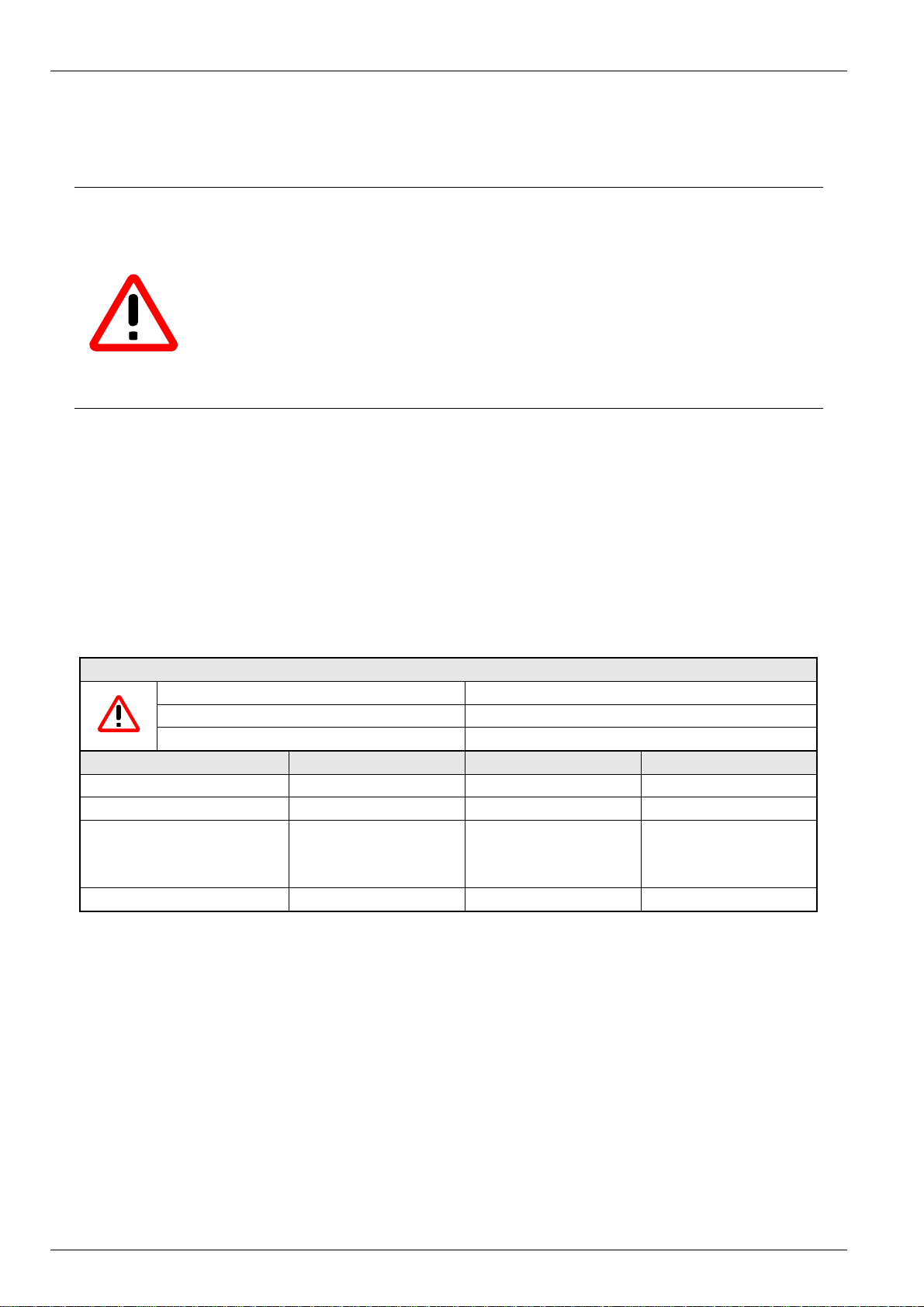
Wiring terminals shall be marked to indicate the proper
connections and tightening torque:
Terminal Tightening torque Cable cross-section
Main supply (Molex 72 / Weko 983) 1,1 Nm / 10 Ib-in 2,5 mmP
Control terminals / MFR (Phönix MKDSN 1,5) 0,6 Nm / 5,3 lb-in 1,5 mmP
Motor / Brake (Phönix GMKDS 3) 0,6 Nm / 5,3 lb-in 1,5 mmP
1.5.2 European EMC guideline
1 General information
UL File: E171342
2
P
/ 20-12 AWG
2
P
/ 30-14AWG
2
P
/ 30-12AWG
If the NORDAC trio SK 300E is installed according to the recommendations of
these operating instructions, it meets all EMC directive requirements, in
accordance with the EMC product standard for motor-operated systems EN
61800-3.
BU 0300 EN Subject to technical alterations 9
Page 10
NORDAC trio SK 300E Manual
r
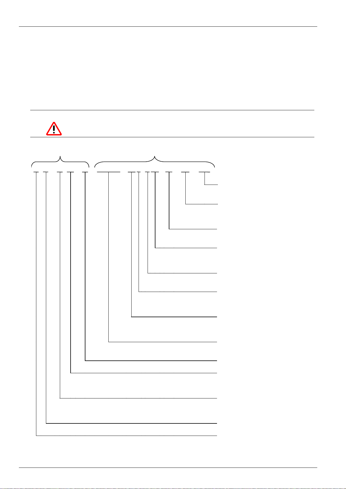
1.6 Nomenclature / Type code
The NORDAC trio SK 300E frequency inverter has the same nomenclature as other NORDAC frequency
inverters. The information contained therein can be determined in the same way. The type classification of the
frequency inverter contains the device type, the nominal output, data on mains voltage, the noise suppression
filter, protection class and any special device designs. The nomenclature of the adapter unit, which represents
the link between the motor and frequency inverter, can be found in the designation of the geared motor. This
clearly identifies a drive unit with SK 300E. The nomenclature contains the abbreviation of the adapter unit,
version and variant of the components, the protection class and the motor winding circuits.
NOTE
The nomenclature must always be provided in orders and for service and support cases!
Adapter unit Frequency inverte
TI 0 / 1 C - S - SK 300E - 55 0 - 3 40 - B
-C -ABC
Special device design
(3 letters)
IP protection class of frequency inverter:
space = IP55 design (Standard)
C (coated) = IP66 design (Option)
Integrated noise suppression filter:
B = Class B1
Mains voltage:
x23 = 230V
x40 = 400V
Number of mains phases:
3 = 3 phase
Digits before comma for power:
0 = 0.xx,
1 = 0x.x0
Device nominal power (xx):
37 = 0.37kW …
40 = 4.00kW
Device series:
SK 300E
Star / Delta circuit
IP protection class of adapter unit:
space = IP55 design (Standard)
C (coated) = IP66 design (Option)
Variant 1 / 2 (...of adapter unit)
1 = with screwed cable glands
2 = Harting connector attachment
Version 0
Trio Interface (trio- adapter unit)
10 Subject to technical alterations BU 0300 EN
Page 11
1 General information
1.7 Design with protection class IP55 / IP66
The frequency inverter NORDAC trio SK 300E can be ordered in any size and therefore any power stage with
the protection classes IP55 (Standard) or IP66 (Option).
The protection class IP66 must
There are no restrictions in both protection classes regarding the function of the available adapter units,
technology units or customer units (see the applicable chapters). The type designation of the SK 300E and the
modules in the protection class IP66 is given an additional code "-C" (coated → coated board) to differentiate
the IP55 and IP66 protection classes.
IP55 design
:
The IP55 design of the SK 300E is generally available as the standard design. Both variants (motor-
integrated, close to motor) are available here. In addition, all adapter units, technology units and customer
units are available for this design.
IP66 design
:
The IP66 design is a modified option compared to the IP55 design. Both variants (motor-integrated, close to
motor) are also available here. The modules available to the IP66 design (adapter units, technology units and
customer units) have the same functionalities as the corresponding IP55 design modules.
Note
The modules for the IP66 design are identified by an additional "-C" and are modified according to the
following special measures!
Special measures:
• Coated circuit boards
• Low pressure tests
Æ A free M12 screwed connection is required for low pressure testing. Following successful
testing, a membrane valve is inserted here. These screw connections are therefore not
available to the customer.
• Membrane valve for pressure compensation during temperature changes
Note
It must
be ensured in the IP66 design that the cable lines and cable connections are carefully
matched so that no leaks occur in the SK 300E or any other problems occur that could affect the
maintenance of the IP66 protection class!
always be included in the order when ordering!
BU 0300 EN Subject to technical alterations 11
Page 12

NORDAC trio SK 300E Manual
2 Assembly and installation
2.1 Motor-integrated and close to motor layouts
Motor-integrated layout:
In the motor-integrated version, the SK 300E frequency inverter is mounted directly on the motor with an
adapter unit (SK TI 0/1 or 0/2) and is therefore integrated in the drive. This version is the standard version.
Optional technology unit
and customer unit
Close to motor design:
The close to motor SK 300E design means that the frequency inverter can be mounted close to the motor, i.e.
on a wall or a machine scaffold for example. A wall-mounting kit is required for this (see Chap. 2.2).
Optional technology unit
and customer unit
12 Subject to technical alterations BU 0300 EN
Page 13

2.2 Wall mounting kit
(SK WMK-DA1, Part. No. 275115100)
The geared motor and inverter can be installed
separately, using the wall mounting kit, so that
the SK 300E can be used close to the motor.
With this option the frequency inverter can be
mounted directly on a wall or machine scaffold
with a very high protection class of IP55 / IP66.
2 Assembly and installation
Installation
The wall mounting kit must be fitted using the
hole pattern below.
160 mm
125 mm
128 mm
157,5 mm
Commissioning
The wall-mounting kit (SK WMK-DA1) is a
modular design system, i.e. an adapter unit
must be selected first (SK TI 0/1 or SK TI 0/2)
so that the SK 300E frequency inverter can be
fitted to the wall-mounting kit.
When delivered, the wall-mounting kit with the
SK 300E is ready for connection to mains,
motor and control cables. The frequency
inverter only needs to be pushed on after the
cables are connected.
Different datasets from the frequency inverter
and "electronic name plate" will be displayed in
the operating display (E8.6) and by the red
LED during initial commissioning only. This
display serves to inform the operator; the
message is acknowledged by an Enable signal
and the datasets are then synchronised. After
the factory settings are loaded (P523) and the
motor data are set, the frequency inverter is
ready to be switched on.
43 mm
Fastening holes in detail:
12 mm
5,5 mm
Module contents
Note
Data for power derating in the close to motor version at high ambient temperatures can be found in
Chap. 9.1 General Data.
BU 0300 EN Subject to technical alterations 13
Page 14

NORDAC trio SK 300E Manual
2.3 Installation
An adapter unit with the correct connection terminals and appropriate plug-in connections for the frequency
inverter is always required for the SK 300E. There are two types of adapter unit, the SK TI 0/1 (-C) and SK TI
0/2 (-C), and their different properties are described in the following chapters.
The adapter units are both suitable for the inverter sizes 1 and 2.
2.3.1 Adapter unit SK TI 0/1
(SK TI 0/1, Part. No. 275115010)
(SK TI 0/1-C, Part. No. 275175010)
The adapter units SK TI 0/1 and SK TI 0/1-C are cast enclosures which are fitted with different sizes of cable
glands on both sides. They are fully fitted with blind plugs.
The following are available:
3 screw connections M12 (e.g. brake cable), 2 connections in the SK TI 0/1-C
4 screw connections M20 (e.g. supply voltage)
1 screw connection M16 (for connection socket M12 of the ParameterBox SK PAR-2H)
Components of the adapter unit TI 0/1
:
Cast enclosure CIU - customer interface unit
Cable for motor
U-V-W connection
Cable for motor PTC Screw accessories
M12 socket
ATTENTION
The adapter unit SK TI 0/1 is available for the protection class IP55 and the adapter unit SK TI
0/1-C for IP66. Otherwise, the functionality and dimensions of both adapter units are identical.
However
protection class.
special measures (see Chap. 1.7) are implemented in the IP66 version to maintain this
14 Subject to technical alterations BU 0300 EN
Page 15

2 Assembly and installation
2.3.2 Adapter unit SK TI 0/2
(SK TI 0/2, Part. No. 275115020)
(SK TI 0/2-C, Part. No. 275175020)
The adapter units SK TI 0/2 and SK TI 0/2-C have 2 mounting flanges on the sides to which various adapter
plates with different types of cable glands or motor connectors can be mounted. The standard design always
has 2 x M12 screw connections and an adapter plate with the following screw connections on the one side:
2 screw connections M20 (e.g. supply voltage)
1 screw connection M16 (for connection socket M12 of the ParameterBox SK PAR-2H)
The adapter plate with the screw connections is located at III in the standard design.
Cast enclosure CIU - customer interface unit
Cable for motor
U-V-W connection
Cable for motor PTC
ATTENTION
The adapter unit SK TI 0/2 is available for the protection class IP55 and the adapter unit SK TI
0/2-C for IP66. Otherwise, the functionality and dimensions of both adapter units are identical.
However
protection class.
special measures (see Chap. 1.7) are implemented in the IP66 version to maintain this
M12 socket
Screw accessories
BU 0300 EN Subject to technical alterations 15
Page 16

NORDAC trio SK 300E Manual
2.3.3 Motor connector variants
Harting HAN 10E Harting HAN Q8
Motor-mounted (motor-integrated)
EITHER:
Power input (LE)
Æ Mains voltage
Wall mounting
EITHER:
Power input (LE)
Æ Mains voltage
Motor connector Nomenclature Function Part. No.
HAN 10E
HAN Q8
H10E LE Power input 275135000
H10E MA Motor output 275135020
HQ8 LE Power input 275135030
HQ8 MA Motor output 275135050
OR:
Motor output (MA)
Æ Motor line
or motor connector (MA)
Æ Motor connection
16 Subject to technical alterations BU 0300 EN
Page 17

2 Assembly and installation
2.3.4 Adapter plates for SK TI 0/2
The other side of the cast enclosure is available without adapter plate in the standard version. This allows
various adapter plates with different types of cable glands or system connectors to be mounted (e.g. Harting
connector). In addition, it is possible to mount the components listed in the table below to the respective
mounting flanges, replacing the standard adapter plate:
Important! Generally, only the mounting of one
Optional adapter plates:
system connector is possible!
SK DA 4x M16,
Part No. 075119000
SK DA 2x M20, 1x M16,
Part No. 075119010
Adapter plates
SK DA 1x M25, 2x M16,
Part No. 075119020
SK DA Blindplatte,
Part No. 075119040
Type Part. No.
SK DA 4x M16 275119000
SK DA 2xM20, 1xM16 275119010
SK DA 1xM25, 2xM16 275119020
SK DA Blind plate 275119040
BU 0300 EN Subject to technical alterations 17
Page 18

NORDAC trio SK 300E Manual
2.3.5 Mounting the adapter unit
The SK 300E frequency inverter and the (SK TI 0/1 (-C) or SK TI 0/2 (-C)) adapter unit are always completely
mounted and tested when a trio drive (gears + motor + frequency inverter) is delivered. The adapter unit can
also be ordered separately for subsequent mounting on an existing motor or to replace an older motor-
mounted trio frequency inverter.
Note
However, the IP66-conform SK 300E must be mounted at NORD as special measures have to be
implemented. IP66 components retrofitted on site cannot ensure that this protection class is
guaranteed.
The module "Adapter unit" (SK TI 0/1 (-C) or SK TI 0/2 (-C)) contains the following components:
• Cast enclosure (dependent on type of adapter unit)
• customer interface unit (circuit board)
• M12 socket with system connector for RS485 interface
• Screw accessories for attaching the customer interface unit
• Pre-fabricated cable for motor and PTC connections
Procedures:
1. Screw the M12 socket into the connection unit in the cast enclosure, ensuring that it is tight.
2. Mount the cast enclosure on the terminal box stub of the NORD motor with the existing screws in place of
the terminal box. Position the cast enclosure with the dome facing the motor A-side. Retain the motor's
terminal block. Check the adaptability for different motor manufacturers.
3. After the bridges for the correct motor circuit are set, connect the pre-fabricated cables for motor
connection and PTC connection to the respective connection points on the motor.
4. After the cables for the motor connection and PTC are connected to the appropriate terminals on the
customer interface unit (pin assignment, see Chap. 2.6.1 ), the customer interface must be mounted with
the screw accessories in the cast enclosure. It must be ensured that the insulation foil lies on the inner side
of the cast enclosure dome. Both tabs must be pointing to the inside of the cast enclosure.
5. Connect the M12 socket system connector to the appropriate slot (see Fig. 2)
Insolation
foil
Fig. 1: Complete adapter unit Fig. 2: M12 socket connection
18 Subject to technical alterations BU 0300 EN
Page 19

2 Assembly and installation
2.3.6 Mounting the SK 300E frequency inverter
The frequency inverter must first be removed before it can be electrically connected. To do this, undo the 4
fastening screws (Fig. 1) so that the frequency inverter can be lifted off vertically (Fig. 2). After connecting the
supply voltage, the frequency inverter must be vertically reattached (Fig. 3), beginning with the plugs on the
rating plate side which ensure that the inverter is positioned correctly. Further information about attaching
customer units can be found in Chap. 3.3.3 “Mounting the customer unit”
In order to achieve the maximum protection class IP55 / IP66, it must be ensured that all fastening screws of
the frequency inverter are tightened in the specified sequence from screw 1 to screw 4 and with the torque
specified in the table below. Use appropriate screwed connections for the connection line cable cross-section.
Dissipation of heat generated by the inverter occurs via convection . The driven motor must have normal
ventilation. Heat dissipation must not be hindered by significant contamination.
A cover plate with 2 LEDs is normally located on the top side of the frequency inverter. These LEDs show the
status of the frequency inverter. Note that the green LED constantly lights when the mains voltage is applied,
and the red LED according to the error message, e.g. 5 flashes - pause - 5 flashes, etc. for the error E005.
Screw 2 Screw 1
Screw 4 Screw 3
Fig.1: Fastening screws Fig.2: Removing the SK 300E
Frequency inverter size Screw size Tightening torque
S 1 M5 x 35 3.5Nm ± 20%
S 2 M5 x 50 3.5Nm ± 20%
Fig.3: Attaching the SK 300E
Cinch connector
BU 0300 EN Subject to technical alterations 19
Page 20

NORDAC trio SK 300E Manual
2.3.7 Retrofitting an SK 300E frequency inverter
The SK 300E frequency inverter can only be mounted on existing motors when the dimensions of the terminal
box stub matches the dimensions of the adapter unit SK TI 0/1 (-C) or SK TI 0/2 (-C). In order to guarantee the
maximum protection class IP55 / IP66 of the frequency inverter for the entire trio unit, the protection class of
the motor must be modified accordingly.
The adapter unit can be directly attached to size 80 - 100 NORD motors, an additional adapter plate/spacer
with additional seal/cable is required for the sizes 63 - 71 and 112.
NORD motor sizes SK 300E attachment Part. No.
SK 63- 71
SK 80 - 100 Direct attachment of adapter unit
SK 112
Attachment with adapter plate 63 – 71 011015410
(+ additional frame seal) 013097000
Attachment with spacer S 112 013035450
(+ additional terminal box - frame seal) 013097000
Cable kit SK 300E for motor S 112 075115090
075115120
Kit
Adapter unit
Adapter plate (P.No. 011015410)
Seal (P.No. 13097000)
Motor size 63 - 71
Important! The adaptability for other types of motor must be checked individually!
If a trio SK 300E is fitted on site without assistance on an existing motor, the notes regarding Adapter unit
assignment in Chap. 2.6.1 must be complied with.
2.4 Painting
The SK 300E frequency inverter and the corresponding adapter unit are covered in a black powder coating.
These components may not be painted over!!! The geared motor is painted separately.
20 Subject to technical alterations BU 0300 EN
Page 21

2 Assembly and installation
2.5 Wiring guidelines
The frequency inverter has been developed for use in an industrial environment. In this environment, high
levels of electromagnetic interference can influence the frequency inverter. In general, correct installation
ensures safe and problem-free operation. Should limit values in excess of the EMC guidelines be required,
then the following guidelines may be useful.
(1) Ensure that all devices are securely earthed using short earthing cables that have large cross-sections
and which are connected to a common earthing point or earthing rail. It is especially important that
every control device connected to the frequency inverters (e.g. an automation device) is connected,
using a short cable with large cross-section, to the same earthing point as the inverter itself. Flat
conductors (e.g. metal clamps are preferable, as they have a lower impedance at high frequencies.
(2) The PE cable for the motor controlled via the frequency inverter should be connected directly to the
earthing connection linked to the enclosure together with the PE for the relevant frequency inverter
feeder. The presence of a central earthing bar in the control cabinet and the grouping together of all PE
conductors to this bar normally ensures safe operation.
(3) Where possible, shielded cables should be used for control loops. Carefully terminate cable ends and
ensure that the wires do not run over longer sections unshielded.
(4) The shields of analogue setpoint cables should only be earthed on one side on the frequency inverter.
(5) The control cables should be installed as far as possible from power cables, using separate cable ducts
etc. Where cables cross, an angle of 90° should be ensured as far as possible.
(6) Ensure that the contactors in the cabinet are interference protected, either by RC circuits in the case of
DC contactors or by free-wheeling diodes for AC contactors, whereby the interference traps must be
positioned on the contactor coils. Varistors for over-voltage limitation are also effective. This
interference suppression is particularly important when the contactors are controlled by the relay in the
frequency inverter.
(7) Use shielded or armoured cable for the load connections and earth the shielding/armour at both ends (if
the motor is not integrated). If possible, directly at the inverter PE.
(8) A noise suppression filter is always present in the standard device. If the frequency inverter is mounted
directly on the motor, then noise suppression grade Class B1 is achieved. If the frequency inverter is
mounted close to the motor (e.g. wall mounted), noise suppression grade Class A1 is achieved with a
motor cable length of up to 15m (shielded cable).
(9) Select the lowest possible pulse frequency. This reduces the intensity of the electromagnetic
interference generated by the frequency inverter.
The safety regulations must be complied with under all circumstances when
installing the frequency inverter!
NOTE
The control cables, line cables and motor cables must be laid separately. In no case should they be
laid in the same protective pipes/installation ducts.
The test equipment for high voltage insulations must not be used on cables that are connected to the
frequency inverter.
BU 0300 EN Subject to technical alterations 21
Page 22
NORDAC trio SK 300E Manual
2.6 Electrical connection
WARNING
THESE DEVICES MUST BE EARTHED.
Safe operation of the devices presupposes that qualified personnel mount and operate it in
compliance with the instructions provided in these operating instructions.
In particular, the general and regional mounting and safety regulations for work on high voltage
systems (e.g. VDE) must be complied with as must the regulations concerning professional use of
tools and the use of personal protection equipment.
Dangerous voltages can be present at the line input and the motor connection terminals even
when the inverter is switched off. Always use insulated screwdrivers on these terminal fields.
Ensure that the input voltage source is not live before setting up or changing connections to the
unit.
Ensure that the motor is designed for the correct connection curren t .
2.6.1 Assignments for the adapter unit
Maximum capacity
Connection terminal data Type Tightening torque Cable cross-section
Mains connection Molex 72 / Weko 983 1.1 Nm / 10 Ib-in 2.5 mm2 / 20-12 AWG
Controller connections MFR: Phönix MKDSN 1.5 0.6 Nm / 5.3 Ib-in 1.5 mm2 / 30-14 AWG
Motor connection
Mechanical brake
Brake resistor
Cable connections M12 - M16 - M20 - M25 2.5 - 6 - 8.5 - 10Nm
Supply voltage + 5V max. 275 mA
Supply voltage + 15V max. 100 mA
Signal relay max. 24V / 500 mA
Phönix GMKDS 3 0.6 Nm / 5.3 Ib-in 1.5 mm
2
/ 30-12 AWG
22 Subject to technical alterations BU 0300 EN
Page 23

PE- socket = 3~ 400V device
PE- connector = 3~ 230V device
Option
Customer unit
Earth "PE"
2 Assembly and installation
(connection of mains line)
Control connections:
[21] Dig. Input 1
[41] + 5V supply voltage
[40] 0V, GND
[41] + 5V supply voltage
[40] 0V, GND
[42] + 15V supply voltage
[74] RS 485 interface: B (-)
[73] RS 485 interface: A (+)
Termination resistor RS 485 On/Off
[02] Signal relay (error)
[01] Signal relay
(PTC input) (*)
[…] = Terminal No.
L1 L2 L3
PE L1 L2 L3
1
( PE L N - )
2
( PE - N L )
Mains voltage:
3~ 400V / 3~ 230V
1
) 1~ 230V, 0,37-0,75kW
2
) 1~ 230V, 1,1kW
Mains fuse:
See Chap. 8 "Technical data"
-Br +BrU V W
Motor
3~
Mechanical brake
See Chap. 2.6.4
"Electromechanical brake"
-B +B
System connector M12 socket
Earth "PE"
(Additional PE terminal, e.g. for
control line, braking resistor)
External brake resistor
The polarity can be ignored.
(*) The digital inputs can be connected
with the internal 15 V or from the PLC
(7.5 – 33V DC). The data in "(...)"
represent the factory settings.
BU 0300 EN Subject to technical alterations 23
Page 24

NORDAC trio SK 300E Manual
2.6.2 Important information for single phase operation (1~230V)
1. Mains supply is implemented via terminals L1 (L) and L2 (N) for 0.37-0.75kW SK 300E, or L3 (L) and L2
(N) for 1.1kW SK 300E.
This is important for the correct function of the brake rectifier, amongst others.
2. Higher input currents occur with single phase operation. (Chap. 9.2)
3. The mains voltage monitoring must be switched off (Parameter P538 = 0).
2.6.3 Motor temperature protection
The only reliable motor over-temperature protection is a
temperature sensor installed inside the motor winding
(PTC resistor, PTC) This can be connected to a digital
+5V supply voltage
Terminal: “VO +5V”
input and evaluated. A Klixon (bimetal switch) is also
possible.
[41]
Normally, the motor of a trio SK 300E is equipped with a
PTC resistor. In the basic frequency inverter configuration
ig. input
[21]
(without customer unit), 1 digital input is available. This
should normally be used as the PTC input and is set up
as the factory setting.
Switching on can take place directly with the supply voltage (P428 "Automatic start up" 2 = immediate with
mains), via a bus connection, with the ParameterBox, the potentiometer option or with the NORD CON
operating software. If additional control signals are required, then the device must be upgraded with a
customer unit (Basic I/O - SK CU2-BSC, Standard I/O - SK CU2-STD).
If a different digital input is used for the PTC when a customer unit is added, then the relevant parameter
P420...P424 of the digital input must be set to the set value 13.
2.6.4 Electromechanical motor brake
Motor
PTC
An output voltage is generated by the frequency inverter at the terminals -Br/+Br to actuate an
electromechanical motor brake (see Chap. 2.6.1 Assignments for the adapter unit). This is dependent on the
supply voltage present in the frequency inverter. The allocation is as follows:
Mains voltage / AC voltage Brake coil voltage (DC)
400V ~ 180V =
460V ~ - 480V ~ 205V =
230V ~ 105V =
The allocation of the correct brake or brake coil voltage must be taken into account in the design with
reference to the frequency inverter mains voltage.
24 Subject to technical alterations BU 0300 EN
Page 25

2.7 Brake resistor
2 Assembly and installation
During dynamic braking (frequency reduction) of a three-phase
motor, electrical energy is returned to the inverter. In order to
avoid overcurrent switch-off of the frequency inverter, the
integrated brake chopper can convert the returned energy into
heat by connecting an external braking resistor.
2 screw connections, which should be fitted with the appropriate
seals, are enclosed for mounting the braking resistor on the
frequency inverter (M20 for the cable and M12 for the holder).
Suitable installation material is provided to mount the brake
resistor on the adapter unit TI 0/2.
CAUTION
The braking resistance and all other metal components can heat up to temperatures above 70°C.
When mounting, sufficient distance from neighbouring components must be maintained. When working
on the components, allow sufficient cooling time beforehand
Contents of the module (TI 0/1)
Frequency inverter
type
SK 300E-550-340-B …
SK 300E-151-340-B
SK 300E-221-340-B …
SK 300E-401-340-B
SK 300E-550-340-B …
SK 300E-151-340-B
SK 300E-221-340-B …
SK 300E-401-340-B
Braking resistor
Resistor type
SK BR3-120/100-TI 0/1
Part. No. 275140010
SK BR3-82/200-TI 0/1
Part. No. 275140020
SK BR3-120/100-TI 0/2
Part. No. 275140030
SK BR3-82/200-TI 0/2
Part. No. 275140040
Screw connections,
for fastening the
braking resistor
Resis-
tance
120
82
120
82
*) permitted, depending on application, max. 5% ED / 120s (700VDC)
Ω
Ω
Ω
Ω
Continuous
rating
100 W 1.0 kW
200 W 2.0 kW
100 W 1.0 kW
200 W 2.0 kW
*) Pulse
output
(approx.)
Connection
leads,
400mm
FEP AWG
14/19 wh,gy;
PTFE AWG
12/19 gn
Protection
type
IP67
BU 0300 EN Subject to technical alterations 25
Page 26

NORDAC trio SK 300E Manual
2.7.1 BR dimensions
Frequency inverter
type
SK 300E-550-340-B …
SK 300E-151-340-B
SK 300E-221-340-B …
SK 300E-401-340-B
SK 300E-550-340-B …
SK 300E-151-340-B
SK 300E-221-340-B …
SK 300E-401-340-B
Resistor type L W D Hole spacing
SK BR3-120/100-TI 0/1 150 160 65 75
SK BR3-82/200-TI 0/1 255 160 65 75
SK BR3-120/100-TI 0/2 150 160 75 82
SK BR3-82/200-TI 0/2 255 160 75 82
Dimensions (here for frequency inverter size 1 and TI 0/1):
All dimensions in [mm]
65 mm
51 mm
150 mm
140 mm
Wire colour Connector terminal
Brown +B
White -B
Green/Yellow PE
Electrical connection:
→ See also Chap. 2.6.1 "Assignments for the adapter unit"
26 Subject to technical alterations BU 0300 EN
Page 27

2 Assembly and installation
2.8 ATEX Zone 22 for SK 300E (400V devices only)
General information
The NORDAC trio SK 300E can be used in hazardous areas with a suitable modification. It is important that all
safety information given in the operating instructions are strictly complied with for person and property reasons.
This is essential to avoid hazards and damage.
Qualified personnel
It is assumed that all work regarding transport, mounting, installation, commissioning and maintenance is
carried out by qualified personnel. Qualified personnel are those persons who, based on their education,
experience, training and knowledge of applicable standards, specifications, accident prevention regulations
and operating conditions, are authorised to implement the relevant activities required to commission the
frequency inverter. In addition, knowledge of first aid measures and the local rescue facilities is necessary.
ATTENTION
All work must be carried out only when the system is in an electrically voltage-free state.
If the frequency inverter is connected to a motor and a gear, the Ex designations of the motor and
gear must also be taken into account!
Safety information
The increased danger in areas with combustible dust requires that the general safety and commissioning
instructions are strictly complied with. The drive must comply with the specifications in the
6052101
. Explosive dust concentrations can cause explosions if ignited by hot or sparking objects and this can
Project outline No.
cause severe or even lethal injuries to persons and significant damage to property.
It is absolutely essential that the persons authorised to use these motors and frequency inverters in hazardous
areas are trained in their correct use.
ATTENTION
The mains voltage must always be switched off and secured against being switched on again
before opening the frequency inverter to connect the electrical lines or any other work!
Higher temperatures than the maximum permitted surface temperature of the enclosure may be
present inside the frequency inverter and motor. The frequency inverter must therefore never be
opened in hazardous dust atmospheres or removed from the motor!
Unpermitted high dust deposits may not be allowed to build up as they restrict the cooling of the
frequency inverter!
Note: Repairs must only be carried out by Getriebebau NORD.
BU 0300 EN Subject to technical alterations 27
Page 28

NORDAC trio SK 300E Manual
2.8.1 Modified SK 300E for compliance with category 3D
Only a modified frequency inverter is permissible for operating an SK 300E in the ATEX Zone 22. This
modification may only be implemented by NORD. The category 3D SK 300E can be recognised by the closed
technology unit cover (no LEDs) and by the rating plate on the outside of the frequency inverter.
Data on rating plate:
Type SK: 300E 3D TF
Mot. No.: Parts No. FI / Ident. No. FI
IP: 55
KW: According to frequency inverter rating plate
rpm: max. 3000
V D/Y: 400 (FI supply voltage)
Hz: max. 100
S: 1 (only with SK300E-201-340-B = 3)
II 3D T125°C: Frequency inverter
Year of manufacture: Month/Year
SK 300E with mounted rating plate
and without LEDs
II 3D T125°C
2.8.2 Options for ATEX Zone 22
To ensure an ATEX-conform NORDAC trio SK 300E system, permission for hazardous areas must be
available for the optional modules.
• All SK TU2-… technology units are not authorised.
•
All SK CU2-… customer units are authorised.
ParameterBox for operation is authorised.
•
SK ATX-POT ATEX potentiometer is authorised.
•
External braking resistor SK BR3-120/100-TI 0/1 is not authorised.
•
Adapter unit SK TI 0/2 for Harting attachment is not authorised.
•
28 Subject to technical alterations BU 0300 EN
Page 29

2 Assembly and installation
2.8.2.1 ATEX potentiometer
(SK ATX-POT, Part. No. 275142000)
The 3D category SK 300E can be equipped with an ATEX-conform potentiometer which can be used for
setpoint adjustments (e.g. speed) on the device. The potentiometer is inserted in one of the M20 screw
connections.
The selected setpoint can be adjusted with a screwdriver. This component meets the ATEX requirements due
to the screw-on sealing cap. Continuous operation is only permitted with closed sealing cap.
Resistance of potentiometer 10 kOhm
Wire colour on potentiometer Name Terminal
Red +10V [11]
Black AGND /0V [12]
Green
Analog input+
Analog input 1
NOTE: When using a potentiometer with the frequency inverter SK 300E,
a customer unit Basic I/O or Standard I/O is always required!
Example assignment for a Basic I/O (SK CU2-BSC):
Reference voltage +10 V (max. 10 mA) [11]
AGND, 0V [12]
Analog input - [13]
Analog input + [14]
Digital input 2 [Enable right] [22]
Digital input 3 [Enable left] [23]
Digital input 4 [Parameter set switching] [24]
Supply voltage +15 V (max. 100 mA) [42]
Setpoint adjustment
with a screwdriver
[14]
BU 0300 EN Subject to technical alterations 29
Page 30

NORDAC trio SK 300E Manual
2.8.3 Commissioning information
The frequency inverter and motor are suitable for use in Zone 22 according to their designation - nonconductive dusts.
The designation is as follows:
II 3D T125°C
In Zone 22, the cable entries must meet at least protection class IP 55. Unused apertures must be sealed with
blind plugs (minimum protection class IP 55).
The motors are protected against overheating by the frequency inverter. This is implemented by evaluation of
the motor PTC by the frequency inverter. To ensure this function, the digital input 1 must be set to the function
"PTC" (P420 = 13). In addition, it must be ensured that a NORD motor is selected from the motor list (P200).
If a motor from a different manufacturer is used, the motor parameter data (P201 to P207) must be compared
with the motor name plate. In addition, the frequency inverter must be parameterised so that the motor cannot be
operated with a speed greater than 3000 rpm. The "maximum frequency" for a four pole motor must be set to a
value smaller than or equal to 100Hz (P105 ≤ 100). The maximum permissible drive speed of the gears must also
be taken into account here. In addition, the "I²t-Motor" monitoring must be switched on in parameter P535=1.
Necessary parameter settings in overview:
Parameter Setting value Factory setting Description
P105
Maximum
frequency
P200
Motor list
P201 – P207
Motor data
P420
Function Dig.
input 1
P535
I²t motor
≤ 100 Hz [50]
Select the appropriate
motor output
Data as per name plate [xxx]
[13] PTC input [13]
[1] switched on [0] The I²t monitoring of the motor must be switched on.
[0]
Note: Details regarding the permissible option modules for hazardous areas (ATEX Zone 22)
with the frequency inverter NORDAC trio SK 300E can be found in Chap. 2.8.2.
This data is based on a four pole motor. Normally,
the value may only be so big that a motor speed of
3000 rpm is not exceeded.
If a NORD motor is used, the preset motor data can
be called up.
If a motor from another manufacturer is used, the
motor data on the rating plate must be entered.
The digital input 1 must be parameterised as the PTC
to ensure temperature monitoring of the motor.
30 Subject to technical alterations BU 0300 EN
Page 31

2.8.4 EC declaration of conformity
2.8.4 EC declaration of conformity
BU 0300 EN Subject to technical alterations 31
Page 32

NORDAC trio SK 300E Manual
3 Options
3.1 Modular options
By combining different modules for display, control and parameterisation, the NORDAC 300E can be easily
adapted to various demands.
Modules are available for processing analogue and digital signals as well as all common fieldbus systems.
Alphanumerical display and operating modules can be used for simple start-up. For more complex tasks,
various connections to a PC or an automation system can be selected.
Technology units (Technology Unit, SK TU2-…, SK TU2-…-C) are located on top of the frequency inverter
and are accessible from the outside - they are used for manual control or parameterisation, or they can provide
connection to fieldbus systems.
ATTENTION
The technology units SK TU2-… are available for protection class IP55 and technology units
SK TU2-…-C for IP66. It must be noted that the functionality and dimensions of the technology
units are identical for the IP55 and IP66 versions. However,
are implemented in the IP66 version to maintain this protection class.
special measures (see Chap. 1.7)
Customer units (Customer Unit, SK CU2-…, SK CU2-…-C) are installed inside the frequency inverter.
They enable control with digital and analogue signals.
ATTENTION
The customer units SK CU2-… are available for protection class IP55 and customer units
SK CU2-…-C
units are identical for the IP55 and IP66 versions. However,
are implemented in the IP66 version to maintain this protection class.
for IP66. It must be noted that the functionality and dimensions of the customer
special measures (see Chap. 1.7)
WARNING
NOTE
Modules should not be inserted or removed unless the device is free of voltage. The slots may
be used for the applicable modules.
only
Installation of a technology unit separate from the frequency inverter is not
connected directly to the frequency inverter.
possible. It must be
Further detailed information can be found in the Options manuals. -
HTwww.nord.comTH -
32 Subject to technical alterations BU 0300 EN
Page 33

3.2 Technology unit overview
3.2 Technology unit overview
Technology units are optional modules and are screwed onto the top of the frequency inverter. Versions with
protection class IP55 (Standard) and IP66 (optional) are available. Functionality and dimensions of the
technology unit are essentially identical in the IP55 and IP66 versions, however special measures are
implemented for the IP66 version (see Chap. 1.7).
Technology unit
ControlBox
SK TU2-CTR
Part. No.: 275130130
ControlBox
SK TU2-CTR-C
Part. No.: 275170130
PotentiometerBox
SK TU2-POT
Part. No.: 275130060
PotentiometerBox
SK TU2-POT-C
Part. No.: 275170060
Profibus module
SK TU2-PBR
Part. No.: 275130070
Profibus module
SK TU2-PBR-C
Part. No.: 275170070
Profibus module
SK TU2-PBR-KL
Part. No.: 275130065
Profibus module
SK TU2-PBR-KL-C
Part. No.: 275170065
Profibus module
SK TU2-PBR-24V
Part. No.: 275130110
Profibus module
SK TU2-PBR-24V-C
Part. No.: 275170110
InterBus module
SK TU2-IBS
Part. No.: 275130080
InterBus module
SK TU2-IBS-C
Part. No.: 275170080
Protection
type
IP55
IP66
IP55
IP66
IP55
IP66
IP55
IP66
IP55
IP66
IP55
IP66
Description Data
Used for commissioning, parameterisation,
configuration and control of the frequency
inverter.
For direct control of the frequency inverter
without additional installation or setting
This option enables control of the
NORDAC trio SK 300E via the serial
Profibus DP port.
This option enables control of the
NORDAC trio SK 300E via the serial
Profibus DP port.
This option enables control of the
NORDAC trio SK 300E via the serial
Profibus DP port. An additional external
24V supply voltage is required.
This interface enables control of the
NORDAC trio SK 300E via the serial
InterBus port.
4-figure, 7-segment LED display
Keyboard
1 potentiometer 0...100 %
1 switch left-0-right
Profibus interface
Baud rate: 1.5 MBit/s
2x 5 pin M12 system connectors
Profibus interface
Baud rate: 1.5 MBit/s
8 pin terminal
Profibus interface
Baud rate: 12 MBit/s
2x 5 pin M12 system connectors
1 external 24 V power supply
InterBus interface
Baud rate: 500 KBit/s
2x 5 pin M12 system connectors
BU 0300 EN Subject to technical alterations 33
Page 34

NORDAC trio SK 300E Manual
Technology unit
DeviceNet module
SK TU2-DEV
Part. No.: 275130090
DeviceNet module
SK TU2-DEV-C
Part. No.: 275170090
CANopen module
SK TU2-CAO
Part. No.: 275130100
CANopen module
SK TU2-CAO-C
Part. No.: 275170100
AS interface module
SK TU2-AS1
Part. No.: 275130120
AS interface module
SK TU2-AS1-C
Part. No.: 275170120
ATTENTION
Protection
type
IP55
IP66
IP55
IP66
IP55
IP66
The technology units
SK TU2-…-C for IP66. It must be noted that the functionality and dimensions of the technology
units are identical for the IP55 and IP66 versions. However,
are implemented in the IP66 version to maintain this protection class.
Description Data
This interface enables control of the
NORDAC trio SK 300E via the serial
CANbus port with the DeviceNet protocol.
This interface enables control of the
NORDAC trio SK 300E via the serial
CANbus port with the CANopen protocol.
This interface enables the control of
sensors and actuators. In addition, the
NORD trio SK 300E can be parameterised
via the AS interface.
SK TU2-… are available for protection class IP55 and technology units
DeviceNet interface
Baud rate: 500 KBit/s
1x 5 pin M12 system connector
CANopen interface
Baud rate: up to 1 MBit/s
2x 5 pin M12 system connectors
AS interface
2 x 2 M12 5 pin sockets /
connectors
special measures (see Chap. 1.7)
34 Subject to technical alterations BU 0300 EN
Page 35

3.2 Technology unit overview
3.2.1 Mounting the technology unit
The mounting of the technology unit must be implemented as follows:
1. Switch off the mains voltage, observe the waiting period.
2. Undo the 6 fastening screws on the
3. Attach the PE connection on the inside of the technology unit being mounted (see Fig. 2 on next page).
Fit the seal together with the
multipoint connector has full contact.
4. Lightly
tighten all 6 fastening screws.
5. Now tighten the 6 fastening screws in the specified sequence from 1 to 6 (see Fig. 1 on next page) and
with the torque given in the table.
Frequency inverter size Screw size Tightening torque
Size 1
Size 2
blind plate and remove the blind plate (see Fig. 1 on next page).
technology unit on the surface of the frequency inverter. Ensure that the
M4 x 8 1.5Nm ± 20%
Scre w 3 Scre w 4
ATTENTION
Scre w 2 Scre w 1
Scre w 6
Fig. 1: T echnology uni t fastening screws Fig . 2: P E connectio n on th e techno l o g y u n it
Scre w 5
Operation is not permitted if there is no secure PE connection to the frequency inverter and to the
technology unit!
BU 0300 EN Subject to technical alterations 35
Page 36

NORDAC trio SK 300E Manual
3.2.2 ControlBox
(SK TU2-CTR, Part. No. 275130130)
(SK TU2-CTR-C, Part. No. 275170130)
This option is used as a simple parameterisation, display and control tool for the
frequency inverter SK 300E.
Features:
• 4-figure, 7-segment LED display
• Direct control of a frequency inverter
• Display of the active parameter set and operating values
After mounting the ControlBox and switching on the mains supply, horizontal
dashes are displayed in the 4 figure, 7 segment display. This display signals the
operational readiness of the frequency inverter.
If a jog frequency is preset in parameter P113, the display alternates between 0.0Hz and the value in P113.
If the frequency inverter is enabled, the display changes automatically to the operating value selected in
parameter >Selection Display value< P001(factory setting = actual frequency).
The actual parameter set is shown by the 2 LEDs next to the display on the left in binary code.
NOTE
The digital frequency setpoint is factory set to 0Hz. To check whether the drive
is working, a frequency setpoint must be entered with the key or a jog frequency via the
respective parameter >Jog frequency< (P113).
Settings should only be implemented by qualified personnel, strictly in accordance with the warning
and safety information.
ATTENTION : The motor may start immediately after pressing the START key !
36 Subject to technical alterations BU 0300 EN
Page 37

ControlBox functions:
Switching on the frequency inverter. The frequency inverter is now enabled with the set jog frequency
(P113). A preset minimum frequency (P104) may at least be provided. Parameter >Interface< P509
must = 0.
a) To switch off (block) the frequency inverter during operation. The output frequency is reduced to the
absolute minimum frequency (P505) and the frequency inverter shuts down.
b) During parameterisation, the operating value display P000 (starting display after mains ON) can be
7-segment
LED
display
LEDs
1
2
called up from any parameter.
a) Shows the current operating value set during operation (selection in P001) or an error code.
b) During parameterisation, the parameter numbers or the parameter values are shown. When
switched off, but operational, four dashes "_ _ _ _" are displayed or, if a setpoint frequency > 0Hz is
set in P113, this value will flash.
a) The LEDs signal the actual operating parameter set during operation.
b) During parameterisation, the parameter set being parameterised is displayed.
a) The motor rotation direction changes when this key is pressed. "Rotation to the left" is indicated by
a minus sign.
Block the key with parameter P540.
b) To cancel a value changed during parameterisation mode, press this key.
3.2 Technology unit overview
1
2
Attention ! Take care when operating pumps. screw conveyors, ventilators, etc.
= P1
1
2
= P2
a) Press key to increase the frequency.
b) During parameterisation, the parameter number or parameter value is increased
a) Press the key to reduce the frequency.
b) During parameterisation, the parameter number or parameter value is reduced.
a) Press "ENTER" to store a changed parameter value, or to switch between parameter number and
parameter value.
NOTE: If a changed value is not to be stored, the key can be used to exit the parameter without
storing the change.
b) When operating with the keyboard control, the actual frequency value can be saved in parameter
P113 Jog frequency. This is then the starting value when the START key is used to enable.
BU 0300 EN Subject to technical alterations 37
Page 38

NORDAC trio SK 300E Manual
Controlling the frequency inverter with the ControlBox
The frequency inverter can only be controlled via the ControlBox, if it has not previously been enabled via the
control terminals or via a serial interface (P509 = 0).
If the START key is pressed, the frequency inverter switches to the operating display (selection P001).
The frequency inverter delivers 0Hz or a higher set minimum frequency (P104) or jog frequency (P113).
Parameter set display
Emergency stop
(press simultan e ously)
START
Rotation directi on re versal
(di r ec ti o n key)
Decrease frequency
Parameter set display:
The LEDs indicate in the display the actual operating parameter set and during parameterisation (≠ P000) the
actual parameter set being parameterised.
The parameter set can also be changed during operation via the parameter P100 (control via ControlBox).
Frequency setpoint:
The actual frequency setpoint depends on the setting in the parameters jog frequency (P113) and minimum
frequency (P104). This value can be altered during keyboard operation with the value keys
permanently stored in P113 as the jog frequency by pressing the ENTER key.
Emergency stop:
Set frequency = 0Hz
(press simultaneously)
Store actual frequency as
STOP
jog frequency
(Enter key)
Increase frequency
and and
By simultaneously pressing the STOP key and the "Change direction key" , an emergency stop can be
initiated.
38 Subject to technical alterations BU 0300 EN
Page 39

3.2 Technology unit overview
Parameterisation with the ControlBox
The parameterisation of the frequency inverter can take place in the various operating states. All parameters
can always be changed online. Switching to the parameter mode occurs in different ways depending upon the
operating states and the enabling source.
1. If there is no enable (if necessary, press the STOP key ) via the ControlBox, control terminals or a
serial interface, it is still possible to switch to the parameterisation mode directly from the operating
value display with the value keys
2. If an enable is present via the control terminals or a serial interface and the frequency inverter is
producing an output frequency, it is also possible to switch to the parameterisation mode directly from
the operating value display using the value keys
3. If the frequency inverter is enabled via the ControlBox (START key ), the parameterisation mode
can be reached by pressing the START and ENTER keys (
Switching back to the control mode is achieved by pressing the START key .
4.
Parameter set display
Switching from
parameterisation to control
(see Point 3)
Previous menu group or
parameter number
or . Æ P 0 0 1 ... P 9 9 9
or . Æ P 0 0 1 / P 9 9 9
+ ) simultaneously.
Simultaneous pressing:
Switching from control to
parameterisation w hile th e
dri ve is run ning
(see Point 3)
Select menu group,
display parameter value
(Enter key)
Next menu group or
parameter number
One level each time back to
the operating value display
Changing parameter values
To access the parameter section, one of the value keys or must be pressed. The display changes to
the parameter display
It is therefore possible to scroll forwards and backwards within this section.
Each parameter has a parameter number
starts in Chapter 7 "Parameterisation"
When the required parameter has been selected, press the ENTER key
change the value with the value keys
but not yet stored. Pressing the ENTER key
P 0 0 1 ... P 9 9 9. All parameters are arranged in order in a continuous scroll pattern.
Æ P x x x . The significance and description of the parameters
to display the parameter value and
or . A flashing display indicates that the value has been changed
stores the changed value.
BU 0300 EN Subject to technical alterations 39
Page 40

NORDAC trio SK 300E Manual
Menu structure with the ControlBox
Operating val ues display
(or operational)
following mains ON
_ _ _ _
P001
P003
To
change a parameter value, the ENTER key must be pressed when the applicable parameter number
is displayed.
Changes can then be made using the VALUE keys
and leave the parameter.
As long as a changed value has not been confirmed by pressing ENTER, the value display will blink; this value
has not yet been stored in the frequency inverter.
During parameter changes, the display does not blink so that the display is more legible.
P10 0 P20 0 P503
P10 1
P10 2
P113
P2 01
P2 02
P216
P400
P40 1
P40 2
P483
or and must be confirmed with to save them
P50 4
P50 5
P559
P70 0
P701
P707
P9 99
If a change is not
Parameter set display
to be saved, the "DIRECTION" key can be pressed to leave the parameter.
Do not accept
ch anged valu e
(direction key))
Reduce value
Simultaneous pressing:
Value to fact ory setting
Acce pt cha nged valu e
Increase value
40 Subject to technical alterations BU 0300 EN
Page 41

3.2 Technology unit overview
3.2.3 PotentiometerBox
(SK TU2-POT, Part. No. 275130060)
(SK TU2-POT-C, Part. No. 275170060)
The PotentiometerBox can be used as a control unit for various
functions. Selection can be carried out in parameter P549. An infinitely
variable potentiometer and a three-position switch for selecting CW/CCW
operation or Stop are integrated in the module for operation. This is a
control switch that can generate an enable signal. The factory setting
enables direct control of the output frequency in the minimum (P104) and
maximum frequency (P105) ranges.
Note:
The frequency inverter can then only be controlled via the
PotentiometerBox, when the parameter (P509) >Interface< is
programmed for "control terminals or keyboard" (P509 = 0).
LED Description
Green LED [ON]
Red LED [ERROR] Signals actual error by flashing according to the number code of the error.
Signals that mains voltage is present.
3.2.4 DeviceNet module
(SK TU2-DEV, Part. No. 275130090)
(SK TU2-DEV-C, Part. No. 275170090)
DeviceNet is an open communications profile for distributed industrial
automation systems. It is based on the CANbus system.
Up to 64 participants can be linked to one Bus system.
The transfer rate (125, 250, 500 kBit/s) and the Bus addresses are set
using rotary coding switches or the applicable parameters.
DeviceNet status LEDs
Module status LEDs
MS (red/green) Module status
MS (red/green) Mains (bus) status
DS (green) Module status
DE (red) Module error
NOTE: Detailed information can be found in the operating instructions BU 0080 or contact the supplier
of the frequency inverter.
BU 0300 EN Subject to technical alterations 41
Page 42

NORDAC trio SK 300E Manual
3.2.5 Profibus module
(SK TU2-PBR, Part. No. 275130070)
(SK TU2-PBR-24V, Part. No. 275130110)
(SK TU2-PBR-KL, Part. No. 275130065)
(SK TU2-PBR-C, Part. No. 275170070)
(SK TU2-PBR-24V-C, Part. No. 275170110)
(SK TU2-PBR-KL-C, Part. No. 275170065)
Profibus allows numerous different automation devices to exchange data. PLC's, PC's, operating and
monitoring devices can all communicate via a uniform bus in serial bit mode.
PROFIBUS DP is primarily used for communication between sensor and actuator where system response
needs to be very fast. PROFIBUS DP is a suitable alternative to expensive 24-volt parallel signal transmission
and transmission of measured values. This type of PROFIBUS, which is optimised to speed, is used for
instance for operating frequency inverters on automation devices.
Data exchange is specified in DIN 19245 Part 1 and 2 and application-specific upgrades in Part 3 of this
standard. Within the European field bus standardisation process, PROFIBUS is integrated into the European
field bus standard pr EN 50170.
The termination resistor for the last bus participant is located in the Profibus standard plug.
Profibus status LEDs
BR (green) BUS ready
BE (red) BUS error
NOTE: Detailed information can be found in the operating instructions BU 0020 or contact the supplier of the
frequency inverter.
3.2.6 CANopen Bus module
(SK TU2-CAO, Part. No. 275130100)
(SK TU2-CAO-C, Part. No. 275170100)
The CANopen interface on the NORDAC frequency inverter enables the
parameterisation and control of the devices in accordance with CANopen
specifications. Up to 127 participants can be addressed on a single Bus.
A termination resistor can be screwed onto the output of the last
frequency inverter as an end plug. The transfer rate (10kBaud and
1MBaud) and the Bus addresses are set using rotary coding switches or
the applicable parameters.
CANopen Status LEDs
Module status LEDs
NOTE: Detailed information can be found in the operating instructions BU 0060 or contact the supplier of the
frequency inverter.
CR (green) CANopen RUN LED
CE (red) CANopen ERROR LED
DR (green) Module status
DE (red) Module error
42 Subject to technical alterations BU 0300 EN
Page 43

3.2.7 InterBus module
(SK TU2-IBS, Part. No. 275130080)
(SK TU2-IBS-C, Part. No. 275170080)
With InterBus, up to 256 subscribers with different automation devices
can exchange data. PLC's, PC's, operating and monitoring devices can
all communicate via a uniform bus in serial bit mode.
NORDAC frequency inverters are remote bus participants. The data
width is variable (3 words; 5 words), at a baud rate of 500kBit/s
(optional 2Mbit/s). An additional termination resistor is not necessary
as it is already integrated. Addressing is carried out automatically by
means of the physical arrangement of the participants.
An external 24V supply is required for uninterrupted Bus operation.
3.2 Technology unit overview
Module status LEDs
InterBus status LEDs
ST (red/green)
UL (green)
RC (green)
BA (green)
RD (yellow)
TR (green)
Module error/ready
Supply voltage applied.
Remote Check, remote bus to previous InterBus device is OK.
Bus Active, InterBus data are being exchanged (Bus running).
Remote bus disabled, remote bus to next InterBus device is
switched off.
Transmit, data is being transferred from/to participants.
NOTE: Detailed information can be found in the operating instructions BU 0070 or contact the supplier of the
frequency inverter.
3.2.8 AS interface
(SK TU2-AS1, Part. No. 275130120)
(SK TU2-AS1-C, Part. No. 275170120)
Actuator-Sensor-interface (AS interface) is a bus system for the
The
simple field bus level. The transmission principle is a single master system
with cyclical polling. A maximum of 31 slaves (or 62 A/B slaves) can be
operated on an up to 100m long unshielded two-wire cable in any network
structure (tree/line/star). The AS interface cable (yellow) transmits data
and power while a second two-wire cable can be used for a small auxiliary
voltage (24V). Addressing is implemented via the master, which can also
provide other management functions, or via a separate addressing device. The 4 bit reference data (per
direction) are cyclically transmitted with an effective error protection at a maximum cycle time of 5ms.
Transmission of larger data volumes is also possible with some slave profiles (e.g. slave profile 7.4). The bus
system is defined in the
AS Interface Complete Specification.
Status LEDs
Device S/E (red/green)
AS- Int. PWR/FLT (red/green)
Module status/error.
Standard status display for AS interface slaves.
NOTE: Detailed information can be found in the operating instructions BU 0090 or contact the supplier of the
frequency inverter.
BU 0300 EN Subject to technical alterations 43
Page 44

NORDAC trio SK 300E Manual
3.2.9 Retrofit kit, SK TU2 cover
(SK TU2 cover for SK 300E S1/S2, Part. No. 275113050)
The retrofit kit for the NORDAC
SK 300E in the position of the technology unit. This module contains a
blind plate with the same measurements as other technology units, a
suitable seal and 6 screws for fastening.
This retrofit kit is used so that any technology units that are no longer
required, e.g. the PotentiometerBox, can be removed from the SK
300E and the retrofit kit screwed on in its place. This ensures that the
maximum protection class IP55/IP66 is maintained.
In addition, two LEDs are visible from outside the blind plate on the left
side. These indicate the current status of the device.
LED Description
Green LED [ON] Signals that mains voltage is present.
trio SK 300E is screwed on top of the
Red LED [ERROR] Signals actual error by flashing according to the number code of the error.
NOTE
If a technology unit has not been ordered together with the SK 300E, it is always delivered with
a blind cover. This means that an extra retrofit kit does not need to ordered for this SK 300E.
44 Subject to technical alterations BU 0300 EN
Page 45

3.3 Customer unit overview
Customer units are optional modules, which offer a variety of
control inputs and outputs in addition to the standard scope. The
options for controlling the frequency inverter can be modified
according to requirements.
A customer unit can be integrated in each frequency inverter.
After the mains voltage is connected and switched on, it is
automatically recognised by the inverter and the additional
functions are made available. The cable connection is
established using screw connectors. This makes the connection
of devices very easy and convenient.
Customer unit
Basic I/O
SK CU2-BSC
Part. No. 275130010
Basic I/O
SK CU2-BSC-C
Part. No. 275170010
Standard I/O
SK CU2-STD
Part. No. 275130020
Standard I/O
SK CU2-STD-C
Part. No. 275170020
Protection
type
IP55
IP66
IP55
IP66
Description
Simplest customer unit with suitable
number of control signals for simple
usage.
Expanded functionality for all types of
special applications.
3.3 Customer unit overview
Data
Available control connections are
expanded by the following items.
3 digital inputs
1 analogue input 0...10V
0/4…20mA
4 digital inputs
2 analogue inputs 0...10V
0/4…20mA
1 analogue / digital output
ATTENTION
The customer units SK CU2-… are available for protection class IP55 and customer units
SK CU2-…-C
units are identical for the IP55 and IP66 versions. However,
are implemented in the IP66 version to maintain this protection class.
for IP66. It must be noted that the functionality and dimensions of the customer
special measures (see Chap. 1.7)
BU 0300 EN Subject to technical alterations 45
Page 46

NORDAC trio SK 300E Manual
3.3.1 Customer unit Basic I/O
(SK CU2-BSC, Part. No. 275130010)
(SK CU2-BSC-C, Part. No. 275170010)
The Basic I/O customer unit (
control signals for simple control tasks, thereby offering a budget solution for
many cases.
In addition to the controls available in the standard version, the Basic I/O has
one analogue and 3 digital inputs. The analogue differential input can handle
signals from 0...10V, 0...20mA or 4...20mA.
Note: AGND, 0V is the reference potential for the analogue and digital
inputs.
Custome r side
Customer Unit) provides an adequate number of
0...10V, 0/4…20mA
or
potentiometer:
2,0kΩ...10kΩ
Floating contacts or
output of a PLC:
7,5...33V (lo w=0...3,5 V)
Referenc e voltage +10 V (max. 10 m A) [11]
AGND, 0V [12]
Analog inp ut - [13]
Analog inp ut + [14]
Digi tal in put 2 [Enable right] [22]
Digi tal in put 3 [Enable l eft] [23]
Digita l input 4 [Parameter set switching] [24]
Suppl y voltage +15 V (max. 100 m A) [42]
(Maximum terminal c ross-section: 1,5 mm²)
DIP switches:
You can select whether current or voltage setpoints should be used for the analogue input. Set the DIP
switches as follows.
1. S witching the
load resistor for ON = Current setpoint 0/4 ...20 mA
analog input 1 OFF = Voltage setpoint 0...10 V
2. Swit ching a bridge between ON = Bridge closed
termi nals AGND/0V and AIN- OFF = Bridge open
NOTE
With current setpoint setting:
Scaling must be taken into account when operating with a current setpoint of 0/4...20mA.
If 20mA represents a setting of 100%, then parameter P403 "Analog input 1 adjustment 100%" must
be set to 5V!
46 Subject to technical alterations BU 0300 EN
Page 47

3.3.2 Customer unit Standard I/O
(SK CU2-STD, Part. No. 275130020)
(SK CU2-STD-C, Part. No. 275170020)
The Standard I/O
Customer Unit provides the highest functionality of digital and
analogue signal processing for the SK 300E. In addition to the standard
equipment, 2 analogue inputs, 4 digital inputs and 1 analogue/digital output are
available.
The 2 analogue inputs are not differential inputs. The analogue inputs can
process signals from 0...10V, 0...20mA or 4...20mA with a burden resistance that
can be switched via a DIP switch. Either analogue or digital evaluation is possible
at the analogue output to transfer actual operating parameters, e.g. to a display
device or process control system.
Note: AGND, 0V is the reference potential for the analogue and digital inputs.
Customer side
3.3 Customer unit overview
0...10V, 0/4…20mA
or
potentiometer:
2,0kΩ...10kΩ
loating contact or
LC output:
,5...33V (low=0...3,5V)
Reference voltage +10 V (max. 10 mA) [11]
AGND / 0V [12]
Analog input 1 [14]
Analog input 2 [16]
Analog outp ut 1 [17]
Digital inp ut 2 [Ena ble right] [22]
Digital inp ut 3 [Enable left] [23]
Digital inp ut 4 [Parameter set sw itc hing] [24]
Digital inp ut 5 [fixed frequency 1] [25]
Supply voltage +1 5 V (max. 100 mA ) [42]
(Maximum terminal cross-section: 1,5 mm²)
DIP switches:
You can select, for the analogue input, whether current or voltage setpoints should be used. Set the DIP
switches as follows.
1. Switching the
load resistor ON = Stromsollwert 0/4...20 mA
for analog input 1 OFF = Spannungssollwert 0...10 V
2. Switching the
load resistor ON = Current setpoint 0/4...20 mA
for analog input 2 OFF = Voltage setpoint 0...10 V
NOTE
With current setpoint setting:
Scaling must be taken into account when operating with a current setpoint of 0/4...20mA.
If 20mA represents a setting of 100%, then parameter P403 "Analogue input 1 adjustment 100%"
must be set to 5V!
Analogue inputs:
If both analogue inputs are parameterised to the same function, then analogue input 1 has priority
and analogue input 2 has no function!
BU 0300 EN Subject to technical alterations 47
Page 48

NORDAC trio SK 300E Manual
3.3.3 Mounting the customer unit
NOTE
Installation must be carried out by qualified personnel only, paying particular attention to safety
and warning instructions.
Sequence:
1 = Switch off the mains voltage, observe the waiting period.
2 = Undo the fastening screws on the frequency inverter and remove it from the motor.
NOTE
When removing the frequency inverter, note that the capacitor discharge time of 90 seconds
must be waited for and that no contact should be made with the underneath of the frequency
inverter!
3 = Place the CU so that the drill holes approximately match. Press the PCB into place by putting pressure on
to the plastic cover until it clicks into the PCB holders.
(When removing, press the PCB holders back with one hand and lift the CU out with the connection
terminal block.)
4 = Insert fastening screws
(This creates a PE connection, no further connection is required).
5 = Make necessary connections.
6 = Replace frequency inverter and tighten screws.
Sequence in detail Æ See following pages !
Fastenin g screw1
(Me t a l scr e w )
PCB ho lder 1
PCB ho lder 2 Fasten ing screw 2
(PV C s crew)
48 Subject to technical alterations BU 0300 EN
Page 49

Detailed description of mounting the customer unit
1.) Undo fastening screws 2.) Lift frequency inverter off upwards
Fastening screws
3.) Adapter unit without CU. The fastening
screws for the customer unit must be
removed.
Metal screw
3.3 Customer unit overview
4.) Place the customer unit on the PCB holder
and studs so that the internal threads for the
fastening screws are visible.
Studs with internal thread
PVC screw
BU 0300 EN Subject to technical alterations 49
PCB holderPCB holder
Page 50

NORDAC trio SK 300E Manual
5.) Press the customer unit down until it engages in
the PCB holder.
Then insert the fastening screws.
6.) When repositioning the frequency
inverter, ensure that the cinch connectors
on the front of the frequency inverter are
inserted first.
Cinch
connector
PCB holderPCB holder
NOTE: In order to achieve maximum protection class IP55, ensure that the seal is faultless and that all
4 fastening screws are secured correctly!!! The requirement for maximum protection class IP55 for the
trio SK 300E unit is a protection class for the motor equivalent to that of the inverter.
entire
Detailed description of removing the customer unit
7.) Remove both fastening screws and release both
PCB holders...
8.) … and lift the CU out vertically.
50 Subject to technical alterations BU 0300 EN
Page 51

4 Operation and display
4 Operation and display
There are various solutions for operating the SK 300E, dependent upon application. When used on site at the
device, the
as control and parameterisation of the frequency inverter, this also enables operating values to be displayed
and datasets to be saved (see also Chap. 4.2‚ ParameterBox, Handheld variant).
For permanent fixed installation in a control panel, the
The functionality is equivalent to that of the
variant)).
Handheld Variant of the ParameterBox can be connected directly via an M12 connector. As well
ParameterBox is also available as an Installation Variant.
handheld type (see also Chap. 4.3 ParameterBox (Installation
All NORDAC frequency inverters can be controlled and parameterised using the free
conjunction with a laptop or PC, this provides diagnosis tools for simple drive optimisation. Parameter sets and
oscillograms can be saved, edited and archived. Further information can be found in Chap. 5 "NORD CON
software".
NORD CON software. In
Æ Website for downloading NORD CON: > HTwww.nord.comTH <
BU 0300 EN Subject to technical alterations 51
Page 52

NORDAC trio SK 300E Manual
4.1 Control element connection variants
SK 300E
NORDAC frequency inverter
SK 300E
Adapter unit
Screw terminals
3,0 m
Part. No. 278910060
Connection cable 300E
4 x 0.75 mm²
Connection
Cable cross-section:
scope of delivery)
... Commercial 4-wire
cables (not included in
Direct to system connector
SK IC1-232/485
42 40 73 74
(pluggable)
Interface converter
Part. No. 276970020
Screw terminals
"Handheld"
ParameterBox
SK PAR-2H
Part. No. 278910100
"Installation"
ParameterBox
SK PAR-2E
Part. No. 278910110
NORD CON
(NORD PAC)
Software (free)
www.nord.com)
Part. No. 6099985
(... or download from
52 Subject to technical alterations BU 0300 EN
Page 53

4.2 ParameterBox (Handheld variant)
(SK PAR-2H, Part. No. 278910100)
The SK PAR-2H ParameterBox is a compact control device
for direct connection to the SK 300E inverter. A suitable
connection cable with an M12 plug contact is already
included with the device. This means that the
ParameterBox can be directly connected to the SK 300E
without additional components.
Special connection cables are required for connection to
other NORDAC inverters or a PC/laptop, which are listed in
more detail in the ParameterBox instruction manual "
0040
".
4.2 ParameterBox (Handheld variant)
BU
Connection to SK 300E
Connection to the trio SK 300E can take place using the
existing M12 socket. The maximum protection class IP55 is
retained for the entire unit by using the special connector
components.
After the mains voltage is switched on the corresponding
device type is automatically recognised.
Note: Further information can be found in the operating
instructions of the ParameterBox "
M12 connector, blue Description Cable
2 (wh) + 5V / 170mA
1 (br) GND
4 (b/w) P+ (A) (RS485 +)
3 (bu) P-(B) (RS485 -)
BU 0040"
Length 3m
4 x 0.75mm²
BU 0300 EN Subject to technical alterations 53
Page 54

NORDAC trio SK 300E Manual
4.3 ParameterBox (Installation variant)
(SK PAR-2E, Part. No. 278910110)
The SK PAR-2E ParameterBox is a compact control device for control panel
installation. Up to 5 frequency inverters can be connected via the plug-in
connection terminals. Protection class IP66 is complied with on the front side
when installed.
A connection cable for the ParameterBox is not included in the scope of
delivery. A commercial 4-wire cable with a recommended cable cross-section
of 0.75mm
regulations.
The 15V supply voltage for the ParameterBox is normally drawn from the
frequency inverter.
Mechanical installation in a control panel
For installation in the control cabinet door or the control panel, a cut-out of 137mm x 82mm (tolerance +/- 1mm)
must be made. The sealed unit must be inserted in the pre-processed cabinet panel. There are 6 screws (M3 x
7mm) for securing the unit to the interior of the control panel. The ParameterBox is now mounted securely on
the switching cabinet door and has maximum protection class IP66 on the front side, if mounted correctly.
The electrical connection of the ParameterBox SK PAR-2E can take place in the installation variant via the
internal screw terminals 1-4. Exact assignment of the terminals can be seen in the following section.
2
can be used in compliance with the general installation
Control cabinet interior
Å
Control cabinet front
Æ
Seal
137 mm
35 mm
+/-1mm
73 mm
90 mm
82 mm
+/-1mm
80 mm
100 mm
146 mm
136 mm
162 mm
35 mm
Seal
Fastening screws
6 x M3 x 7mm
(nuts and washers are included)
54 Subject to technical alterations BU 0300 EN
Page 55

4.3 ParameterBox (Installation variant)
SK PAR-2E electrical connection
The ParameterBox SK PAR-2E is connected via the plug-in screw terminals, which are located inside the
ParameterBox
Number Description Terminals
42 + 4.5 … 30V
40 GND
73 P+ (A) RS485 +
74 P-(B) RS485 -
Supply voltage
The +15V supply voltage for the ParameterBox can normally be drawn from the connected frequency inverter.
However, if several frequency inverters are linked together, ensure that only one frequency inverter is tapped
for voltage and not several inverters! The frequency inverter with the shortest cable distance to the
ParameterBox should be selected for this.
Communication via RS485
With connection of several frequency inverters in series (as diagram below), ensure that the ParameterBox is
the first or last participant in the bus system. A termination resistor (approx. 120
frequency inverter at the other end of the entire bus system. A termination resistor of this type is included as
standard with the SK 300E.
.
with +15V / 60mA
0.14…1.5 mm²
Ω) must be provided for the
Control cabinet
SK PAR-2E
Mat. No. 278910110
SK 500E
SK 700E
Geared motor with SK 300E
in field
NOTE: For further information, see the ParameterBox instruction manual BU 0040.
BU 0300 EN Subject to technical alterations 55
Page 56

NORDAC trio SK 300E Manual
4.4 Functions of the ParameterBox
Language settings
In order to set the ParameterBox to the language of the respective operator, see the following explanation. A
query as to whether German or English language is required is displayed during the first switch on. The
following start data is then displayed:
300E 0.75kW/3 BSC 1
> NORDAC <
Frequency inverter
ONLINE U1 P1 EReady
1.) Press the
2.) Parameter P1301 is displayed with "Language : Deutsch"
3.) Press the
4.) English, Francais, Espanol, Sverige, Nederlands
5.) Press
6.) Press the
key 4x Æ "Options" and for Enter.
to select any of the languages in the following sequence:
‘Enter’ to switch to the language displayed/selected.
keys 2x together to return to the start.
56 Subject to technical alterations BU 0300 EN
Page 57

4.4 Functions of the ParameterBox
Display
After the ParameterBox is connected and the mains voltage for the inverter is switched on, an automatic "Bus
scan" takes place. The ParameterBox identifies the connected frequency inverter(s). The frequency inverter
type and its actual operating status can be seen in the following display.
300E 0,75kW/3 BSC 1
Inverter type
> NORDAC <
Frequency inverter
ONLINE U1 P1 EReady
Actual status of
the inverter
In the standard display mode, 3 operating values and the actual frequency inverter status can be displayed
simultaneously.
The operating values displayed can be selected from a list of 8 possible values (in Menu>Display</>Values for
display< P1004).
Current actual values for
the selected operating
values and their
applicable units
Inverter type
300E 0,75kW/3 BSC 1
Fi/Hz U/V I/A
Customer unit
Menu structure level
45.0 190 1.4
ONLINE U1 P1 R RUNNING
Current
ParameterBox status
Inverter
selected
Active parameters
in inverter
Actual status of
the inverter
NOTE
The digital frequency setpoint is factory set to 0Hz. To check whether the motor is working, a
frequency setpoint must be entered with the
level >Parameterise<, >Base parameters< and the respective parameter >Jog frequency< (P113)
Settings must be carried out by qualified personnel only, paying particular attention to safety and
warning instructions.
ATTENTION : The motor may start immediately after pressing the START key!
key or a jog frequency via the respective menu
BU 0300 EN Subject to technical alterations 57
Page 58

NORDAC trio SK 300E Manual
Operation
LCD
Display
Graphic-capable, backlit LCD display for displaying operational values and parameters for the
connected frequency inverter(s) and ParameterBox parameters.
Use the
Press the
The contents of individual parameters can be altered with the
Press the and keys together to load the factory settings of the parameter selected.
When controlling the frequency inverter using the keyboard, the frequency setpoint is set using the
VALUE keys.
Press the
Note: If a parameter is exited without a new value being stored, then one of the SELECTION keys
can be used for this purpose.
If the inverter is to be controlled directly from the keyboard (not control terminals), then the actual
setpoint frequency can be stored under the Jog Frequency parameter (P113).
Selection keys to move through the menu levels and within the individual menu items.
and keys together to go back one level.
VALUES keys.
ENTER key to select a menu group or accept the changed menu items or parameter values.
START key for switching on the frequency inverter.
STOP key for switching off the frequency inverter.
Note: Can only be used if this function
has not been blocked in parameter P509
or P540.
ON
ERROR
The rotational direction of the motor is switched by
pressing the
indicated by a minus sign.
Attention! Take care when operating pumps, screw
conveyors, ventilators, etc.
LED's signal the actual status of the ParameterBox.
The
ON (green) The ParameterBox is connected to the supply voltage and is operational.
ERROR (red) An error has occurred while processing data or in the connected frequency inverter.
Direction key. Rotation direction left is
58 Subject to technical alterations BU 0300 EN
Page 59

4.4 Functions of the ParameterBox
Controlling the frequency inverter
The frequency inverter can only be fully controlled with regards to speed and rotation direction by the
ParameterBox if the parameter >Interface< (
P509 = 0/4) is set to >Control terminals or keyboard< or >USS<
and if it has not already been enabled via the control terminals.
START (Enable)
STOP (No enable)
Change rotation direction
No frequency inverter
control function
Increase frequency
Decrease frequency
Store actual frequency
NOTE
If the frequency inverter is enabled via the keyboard
frequency inverter in the Menu >Parameterisation< >Basic parameters< in the >Parameter set<
parameter (P100) is used.
The parameter set cannot be changed during operation. A change in P100 is only accepted when the
output frequency has passed once through zero.
The change in the parameter set must be confirmed with the
or .
Attention: Following the START command, the frequency inverter may start up immediately with a
pre-programmed frequency (minimum frequency P104 or jog frequency P113).
, then the parameter set selected for this
key and then activated by and
BU 0300 EN Subject to technical alterations 59
Page 60

NORDAC trio SK 300E Manual
Menu structure of the ParameterBox
The menu structure consists of various levels that are each arranged in a ring structure. Press the ENTER
( ) to go to the next level. Simultaneous operation of the SELECTION keys moves the menu back one
key
level (
and ).
300E 3,0kW /3 STD 1
Fi/Hz U/V I/O
45.0 360 3.4
ONLINE FU P1 R RUNNING
Display 1
P1001 2
Bu s sca n
P1002 2
FI selectio n
P1003 2
Display m ode
P1004 2
Values for display
P1 005 2
Stan dardi sation factor
P0 2
Ba ck
Param eterisation 1
Operating displays 2
>ENTER< (t o le ve l 3 .)
Basic parameters 2
>ENTER< (to leve l 3.)
Motor data 2
>ENTER< (t o le ve l 3 .)
Inverter menu s tructu re,
dependent on
installed options
(e.g. posicion, etc.)
Æ Chap. 5 Parameterisation
P0 2
Back
U1 U2 U3 U4 U5
1 - - - -
OK - - - -
100
Parameter 1
administration
P1201 2
Copy - Source
P1202 2
Copy - Target
P1203 2
Copy - Start
P1204 2
Load fact ory setting s
P1205 2
Delete memory
P0 2
Back
Options 1
P1301 2
Language
P1302 2
Op erati ng m ode
P1303 2
Automatic bus scan
P1304 2
Con trast
P1305 2
Set password
P1306 2
Box password
P0
P1307 2
zurück
Reset box p arame ter
P0
P1308 2
zurück
NORDAC p-box
P0 2
Back
Version 3.7
ATTENTION
The parameters of the menu groups
>Options< (P13xx) in level 1 are exclusively ParameterBox parameters and do not have anything to
do directly with the frequency inverter parameters.
>Display< (P10xx), >Parameter administration< (P12xx) and
Access to the frequency inverter menu structure is gained via the >Parameterisation<
menu. The description regarding the parameterisation of the SK 300E starts in Chap. 7
General information.
60 Subject to technical alterations BU 0300 EN
Page 61

4.4 Functions of the ParameterBox
Parameterising with the ParameterBox
To enter the parameterisation mode, the menu group >Parameterisation< must be selected in the menu level
1. Pressing the
following graphic shows how the control elements of the ParameterBox are used for the parameterisation of a
frequency inverter.
Selection forward Increase value
ENTER key ( ) opens the parameter level of the connected frequency inverter. The
Simultaneous operation
→ one menu level back
Selection back
Simultaneous operation
→ Load factory settings
of parameter
Reduce value
One menu level forward
or
Accept parameter value
BU 0300 EN Subject to technical alterations 61
Page 62

NORDAC trio SK 300E Manual
Screen layout during parameterisation
If the setting of a parameter is changed, the value flashes until it is confirmed with the ENTER key ( ). To
load the factory setting of the parameter to be edited, both
together. To store this change, the setting must also be confirmed with the
VALUE keys ( and ) must be pressed
ENTER key.
If the change is not to be stored, then pressing one of the
previously stored value and pressing a SELECTION key again will exit the parameter.
Actual parameter to be
edited (No.)
Actual parameter to be
edited (Text)
Actual parameter
value
Current
ParameterBox
status
Selected frequency
P102 PS1
Start-up time
ONLINE U1 P1 E BLOCK
inverter
2,90 s
SELECTION keys ( or ) will call up the
Actual parameter
data set to be edited
3
Active parameter data set
in control medium
Menu
structure level
Status of the
frequency inverter
Note: The display in the lower line is used to display the actual status of the ParameterBox and the
frequency inverter being controlled.
62 Subject to technical alterations BU 0300 EN
Page 63

4.5 Parameters of the ParameterBox
4.5 Parameters of the ParameterBox
The following main functions are assigned to the menu groups:
Menu group No. Main function
Display (P10xx):
Parameterisation (P11xx):
Parameter administration (P12xx): Copy and save complete parameter sets from storage objects and frequency
Options (P13xx):
Selection of operating values and display layout
Parameterisation of the connected inverter and all storage objects
inverters
Setting the ParameterBox functions and all automatic processes
Menu group < Display> (P10xx)
Parameter Setting value / Description / Note
P1001
Bus scan
P1002
FI selection
P1003
Display mode
P1004
Values for display
P1005
Standardisation
factor
A bus scan is initiated with this parameter. During this process a progress indicator is shown in the
display.
After a bus scan, the parameter is "Off".
Depending on the result of this process, the ParameterBox goes into the "ONLINE" or "OFFLINE"
operating mode.
Selection of the actual object to be parameterised/controlled.
The display and further operating actions refer to the item selected. In the frequency inverter
selection list, only those devices detected during the bus scan are shown. The actual object
appears in the status line.
Note: If an error has occurred in a connected frequency inverter, it can be acknowledged
Value range: U1 - U5
Selection of the operating values display for the ParameterBox
Standard Any 3 values next to each other
Large size display 1 value (any) with unit
List Any 3 values listed with units
Selection of a display value for the actual value display of the ParameterBox.
The value selected is placed in the first position of an internal list for the display value and is then
also used in the Large Display mode.
Possible actual values for the display: Actual frequency Voltage Current
Speed of rotation Torque current Setpoint frequency
Link voltage Bus actual value1 non-stand.
The first value on the display list is scaled with the standardisation factor. Should this
standardisation factor deviate from 1.00, the unit of the scaled value is no longer displayed.
Value range: -327.67 to +327.67; Resolution 0.01
by selecting the frequency inverter.
BU 0300 EN Subject to technical alterations 63
Page 64

NORDAC trio SK 300E Manual
Menu group < Parameterisation> (P11xx)
Parameter Setting value / Description / Note
P1101
Object selection
Selection of the object to be parameterised.
The ongoing parameterisation process relates to the object selected. Only the devices and storage
objects detected during the bus scan are displayed in the selection list.
Note: This parameter is not shown if only one device is recognised and there is no storage
object in the ParameterBox.
Value range: U1 - U5 and S1 - S5
Menu group < Parameter administration > (P12xx)
Parameter Setting value / Description / Note
P1201
Copy - Source
P1202
Copy - Target
P1203
Copy - Start
P1204
Load factory
settings
Selection of the actual source object to be copied.
In the selection list, only the frequency inverters and storage objects detected during the bus scan
are shown.
Value range: U1 – U5 and S1 - S5
Selection of actual target object to copy.
In the selection list, only the frequency inverters and storage objects detected during the bus scan
are shown.
Value range: U1 – U5 and S1 - S5
This parameter triggers a transfer process, whereby all the parameter data sets selected in
– Source<
While data is being overwritten, an information window appears with acknowledgement. The
transfer starts after acknowledgement.
With this parameter, the parameter data sets of the object selected are described with factory
settings.
This function is particularly important when editing storage objects. It is only via this parameter that
a hypothetical frequency inverter can be loaded and edited with the ParameterBox.
Value range: U1 - U5 and S1 - S5
are transferred to the object specified in the >Copy – Target< parameter.
>Copy
P1205
Delete memory
In this parameter the data in the selected storage medium is deleted.
Value range: S1 - S5
64 Subject to technical alterations BU 0300 EN
Page 65

Menu group < Options> (P13xx)
Parameter Setting value / Description / Note
P1301
Language
P1302
Operating mode
P1303
Automatic bus scan
Selection of languages for operation of the ParameterBox
Available languages: German English French
Spanish Swedish Dutch
Selection of the operating mode for the ParameterBox
• Offline:
The ParameterBox is operated autonomously. No PC or frequency inverter is
connected. The parameter data set of the frequency inverter is not accessed. The
storage objects of the ParameterBox can be parameterised and administrated.
• Online:
A frequency inverter is located at the interface of the ParameterBox. The frequency
inverter can be parameterised and controlled. When changing to the "
operating mode, a bus scan is started automatically.
• PC slave:
A PC is located at the interface of the ParameterBox. The ParameterBox can be
addressed as a slave by the
separate frequency inverters
Ö USS address 1
S1
S2
Ö USS address 2
S3
Ö USS address 3
Ö USS address 4
S4
S5
Ö USS address 5
Setting the switch-on characteristics.
• Off
An automatic bus scan is not implemented. The frequency inverters connected
before switching off must be looked for again after switch-on.
• On
A bus scan is automatically implemented when the ParameterBox is switched on.
4.5 Parameters of the ParameterBox
ONLINE"
NORD CON software. The storage objects log on as
P1304
Contrast
P1305
Set password
P1306
Box password
P1307
Reset Box
parameter
P1308
Software version
Contrast setting of the ParameterBox display
Value range: 0% ... 100%; Resolution 1%
The user can set up a password in this parameter.
If a value other than 0 has been entered in this parameter, then the settings of the ParameterBox
or the parameters of the connected frequency inverter cannot be altered.
If the password function is to be reset, the password selected in the
must be entered here. If the correct password has been selected, than all functions of the
ParameterBox can be used again.
In this parameter the ParameterBox can be reset to the factory setting. All ParameterBox settings
and the data in the storage media will be deleted.
Displays the software version of the ParameterBox. Please note for future use.
>Set Password< parameter
BU 0300 EN Subject to technical alterations 65
Page 66

NORDAC trio SK 300E Manual
4.6 Error messages of the ParameterBox
Display Error
Communication error
200
201
202
203
204 No Array parameter
205 Incorrect parameter type
206
207
Parameter number
not permissible
Parameter value cannot be
changed
Parameter outside
value range
Incorrect
Sub- Index
Incorrect response
identifier
USS interface
Checksum error of
USS interface
Cause
• Remedy
These error messages are due to EMC interferences or
differing software versions of the participants.
• Check the software version of the ParameterBox and that
of the connected frequency inverter.
• Check the wiring of all components and for possible EMC
interference
Communication between frequency inverter and ParameterBox is
faulty (EMC), safe operation cannot be guaranteed.
• Check the connection to the frequency inverter. Use a
shielded cable between the devices. Route the BUS
leads separately from the motor cables.
208
209_1 Inverter not responding
Identification error
220 Unknown device
221
Incorrect status identifier
USS interface
Software version not
recognised
Communication between frequency inverter and ParameterBox is
faulty (EMC), safe operation cannot be guaranteed.
• Check the connection to the frequency inverter. Use a
shielded cable between the devices. Route the BUS
leads separately from the motor cables.
The ParameterBox is waiting for a response from the connected
frequency inverter. The waiting time has elapsed without a response
being received.
• Check the connection to the frequency inverter. The
frequency inverter USS parameter settings were changed
during operation.
Device ID not found.
The connected inverter is not listed in the database of the
ParameterBox; no communication can be established.
• Please contact your Getriebebau Nord dealership.
Software version not found!
The software of the connected frequency inverter is not listed in the
ParameterBox database, no communication can be set up.
• Please contact your Nord supply agency.
66 Subject to technical alterations BU 0300 EN
Page 67

Display Error
222
223
224 Device is not supported
225
ParameterBox operating error
226
227 Sou rce is empty
228
229 Object selected is empty
230 Different software versions
231 Invalid password
232
Inverter extension level not
recognised
Bus configuration has
changed
The connection to the
inverter is blocked
Source and target are
different devices
This combination is not
permitted
Bus scan only during
operation: ONLINE
4.6 Error messages of the ParameterBox
Cause
• Remedy
An unknown component has been detected in the frequency inverter
(Customer unit).
• Please check the components installed in the frequency
inverter
• If necessary, check the software version of the
ParameterBox and the frequency inverter.
A different device to that saved responds when the last bus
configuration is restored.
This error can only occur if the parameter
OFF and another device has been connected to the ParameterBox.
>Auto. Bus Scan< is set to
• Activate the Automatic Bus Scan function.
The frequency inverter type connected to the ParameterBox is not
supported!
• The ParameterBox cannot be used with this frequency
inverter.
Access to a device that is not
error).
ONLINE (previous Time Out
• Carry out a bus scan via the parameter >Bus Scan<
(P1001).
Copying objects of different types (from / to different inverters) is not
possible.
Copying of data from a deleted (empty) storage medium
Target and source for the copying function are the same. The
command cannot be carried out.
Parameterisation attempt of a deleted storage medium
Warning
Copying objects with different software versions can lead to problems
when transferring parameters.
Attempt to change a parameter without a valid Box password being
entered in parameter
A bus scan (search for a connected frequency inverter) is only possible
when in ONLINE mode.
>Box Password< P1306.
BU 0300 EN Subject to technical alterations 67
Page 68

NORDAC trio SK 300E Manual
Display Error
Warnings
240
241
242
243
244
Inverter control error
250 This function is not enabled
251
252
253
Error message from inverter
"Error No.
from
inverter"
Overwrite data?
Æ YES NO
Delete data?
Æ YES NO
Move SW version ?
Æ CONTINUE CANCEL
Move series?
Æ CONTINUE CANCEL
Delete all data?
Æ YES NO
Control command was not
successful
Control is not possible
OFFLINE
Error acknowledgement not
successful
Inverter error
"Inverter error text"
Cause
• Remedy
These warnings indicate that there is a possibly significant change which
needs additional confirmation.
Once the next procedure has been selected, it must be confirmed with
the "ENTER" key.
The function requested is not enabled at the frequency inverter
parameter interface.
• Change the value of the parameter P509 >Interface< of the
connected frequency inverter to the required function.
The control command cannot be implemented by the frequency inverter,
as a higher priority function, e.g. Emergency Stop or an OFF signal to the
control terminals of the frequency inverter, is present
Call up of a control function in
Offline mode.
• Change the operating mode of the ParameterBox in the
parameter
the action.
The acknowledgement of an error at the frequency inverter was not
successful, the error message remains.
An error has occurred at the frequency inverter with the displayed
number. The frequency inverter error No. and error text is displayed.
>Operating Mode< P1302 to Online and repeat
68 Subject to technical alterations BU 0300 EN
Page 69

4.7 Data transfer with NORD CON
4.7 Data transfer with NORD CON
The NORDAC ParameterBox S1 to S5 storage elements can be administrated and archived using the NORD CON
control and parameter software.
To achieve transfer of data, the PC serial interface (RS232) must be connected to the ParameterBox via an
interface converter (SK IC1-232/485, Part. No. 276970020) and suitable connection cable. (M12 Socket/SUBD, Part. No. 278910210). In addition, the interface inverter must be connected to an external supply voltage.
Use the USB/5V adapter for this, it is connected to the interface converter via a cinch connector and to the
PC/laptop via a USB connector.
The following components are required for the ParameterBox Æ PC/laptop connection:
RS232
PC / laptop
5V- USB port
adapter
ParameterBox
SK PAR-2H
Mat.No. 278910100
Adapter M12 SO/SUB-D
for SK PAR-2H Æ SK IC1
Mat.No. 278910210
Interface converter
SK IC1-232/485
Mat.No. 276970020
Adapter USB/5V for
SK IC1-232/485
Mat.No. 278910220
Software
NORD CON
Mat.No. 6099985
(NORD PAC)
In this set-up, communication is controlled by the PC. For this, the ParameterBox must be set in the menu
>Options<, Parameter >Operating mode< (P1302) to the value PC slave. After a bus scan, the NORD
group
CON program will then detect the filed storage objects S1 to S5 as separate frequency inverters with bus
addresses 1 to 5 and display them onscreen.
NOTE
Only frequency inverter parameter data sets already saved in the storage objects can be detected and
edited by the
To edit the data set of a new frequency inverter, the inverter type first has to be set via the
settings (P1204)<
bus scan. The new parameter data set can then be edited with the usual tools.
NORD CON parameterisation software.
>Load factory
parameter. The NORD CON software then detects the new storage object in a new
All NORD CON parameterisation
functions are now available.
BU 0300 EN Subject to technical alterations 69
Page 70

NORDAC trio SK 300E Manual
5 NORD CON software
5.1 General information
NORD CON is a PC program to control and parameterise
frequency inverters manufactured by Getriebebau NORD. The
software can be installed on all computers with the Windows 95,
98, NT, 2000, ME or XP operating systems.
There are two ways to implement the installation of the NORD
CON software. The NORD CON software can either be installed
from the NORD PAC CD (Part. No.: 6099985) or downloaded
from the website >www.nord.com<.
NORD CON can communicate with up to 31 frequency inverters
simultaneously or via the device-specific RS485 interface.
The connection from PC to SK 300E is implemented via the
interface converter
connection cable 300E (Part. No. 278910060).
the
As well as control and parameterisation of the frequency
inverter, operating values can also be displayed. The integrated
oscilloscope function is a helpful tool for optimising drive
systems. The resulting oscillograms – like the parameter data
sets - can be saved, edited and archived.
SK IC1-232/485 (Part. No. 276970020) and
NOTE: Internet site for downloading the PC software NORD CON
>>> HTwww.nord.comTH <<<
Features
• Creation, documentation and storage of frequency inverter parameter settings
• Control of the connected frequency inverters
• Monitoring of connected frequency inverters
• Oscilloscope function
• Creation of macros for test process sequences
• Remote control of connected frequency inverters
Remote control
For commissioning (parameterisation), the known device displays are
simulated, enabling remote control of the frequency inverter in familiar
surroundings.
All possible frequency inverter operating unit functions can be carried out.
Simulation Controlbox
70 Subject to technical alterations BU 0300 EN
Page 71

5 NORD CON software
Oscilloscope function
The function to be recorded can be selected from
various channel settings. A total of 4 channels are
available and are scalable in both time and value
range.
The curves can be saved and archived with the
respective settings and called up at a later time.
Parameterisation
All the connected frequency inverter
parameters can be read, edited, saved or
printed for documentation with
All frequency inverter parameters can be
easily accessed via the parameter name and
the corresponding parameter number. This
means that parameterisation with the PC
software
NORD CON is very transparent and
therefore operation is much easier.
In addition, the parameter characteristics are
available and it is possible to narrow down the
displayed parameters.
NORD CON.
Bsp. Parameterauswahl
Macros
Macros enable simple process flows to be
created for test purposes. This can be very
useful, for instance, for testing during
commissioning of a frequency inverter.
BU 0300 EN Subject to technical alterations 71
Page 72

NORDAC trio SK 300E Manual
6 Commissioning
6.1 Basic settings
The NORDAC trio SK 300E is already set up so that the assigned 4-pole standard motor can be operated
without further presetting.
The frequency inverter is not equipped with a line main switch and is therefore always live when connected to
the power supply. It waits with a blocked output until an enable signal occurs.
Attention
If a digital input is not programmed for enable and the parameter P428 is changed to 2 (=
"Immediate with mains“), the motor will start immediately
The following options for an enable signal are available:
1) An enable signal is generated by pressing the start key when a ParameterBox is connected.
See "Initial check with ParameterBox“on Page 73 .
2) When connected to a PC, an enable can be generated with the START key in the "NORD CON" control
software (see Chapter 5 "NORD CON software", Page 70).
3) An "Enable right" is implemented with the factory setting if a control input is configured, e.g. digital input
2 on the CU Basic I/O or Standard I/O (terminal 22), with the internal 15V supply voltage (terminal 42).
4) By changing the "Automatic start up" parameter P428 to 2 (= "Immediate with mains"), this enable
occurs as soon as the mains voltage is switched on. The requirement for this is that no digital input has
been parameterised for Enable.
Note
In delivery condition, only the most important parameters are visible for eventual parameter
changes. Should it be necessary to change other parameters as well, such as e.g. motor data when
using a different motor, then parameter P003 "Supervisor Mode" must be set to 1, so that all
parameters are visible (see also parameter P003
Visible parameters in delivery condition:
Supervisor mode switched off (P003 = 0), i.e. only a limited number of parameters are visible, all other
parameters are hidden:
Parameterisation with the ParameterBox:
Operating displays Control terminals Information
P001 Selection of the operating display P400 Analog input function 1 P700 Actual error
P003 Supervisor mode P420 Digital input function 1 P701 Old error
Basic parameters
P102 Start-up time P422 Digital input function 3 P744 Upgrade level
P103 Braking time P423 Digital input function 4
P104 Minimum frequency
P105 Maximum frequency
P107 Brake application time
P460 Time watchdog
P424 Digital input function 5
P434 Function relay 1
P435 Standardisation relay 1
Parameterisation with the ControlBox:
Operating displays
P003 Supervisor mode
P421 Digital input function 2 P743 Inverter type
P001 Selection of the operating display
, as all enable conditions have been met.
Æ, Page 78)!!!
72 Subject to technical alterations BU 0300 EN
Page 73

6 Commissioning
6.2 Different motor
Using a different motor to delivery condition:
Note
In order to make the motor parameters visible, first set parameter P003 "Supervisor Mode" to 1
(see also parameter P003
A motor list for standard motors is stored in the device. Select the standard motor in parameter P200 "
The relevant data is loaded automatically in parameters P201 – P208 and must be compared again with the
data on the motor rating plate.
When using other motors, the data from the rating plate of the motor must be input into parameters P201 to
P208.
To determine the
the ENTER key. A single automatic measurement of the stator resistance now takes place. The value
adjusted to the line resistance will be stored. This is dependent on the motor circuit entered in parameter
P207 (star/delta circuit).
stator resistance automatically, parameter P208 must be set to "0" and confirmed with
Æ, Page 78)!!!
Motor list".
6.3 Initial check with the ParameterBox
Check first of all whether all cables are connected correctly and whether all relevant safety precautions have
been taken.
Only then can the mains voltage be applied to the frequency inverter. When the ParameterBox is connected,
the following window appears in the ParameterBox display:
300E 1.5kW/3 BSC
1
> NORDAC <
Frequency inverter
ONLINE I1 P1 EReady
Ensure that the motor can start-up without danger. Press the START
The display changes to:
300E 1.5kW/3 BSC
1
key on the ParameterBox.
Fi/Hz U/V I/O
0.0 27 1.2
ONLINE I1 P1 R RUNNING
Check that the motor is running in the direction required by pressing the
frequency.
The actual output frequency, voltage and current are displayed.
After pressing the STOP key
the display will revert to the previous one.
The following parameters can now be changed if necessary.
BU 0300 EN Subject to technical alterations 73
, the motor stops according to the set braking time. After this time has expired,
- key, thereby increasing the set
Page 74

NORDAC trio SK 300E Manual
6.4 Minimum configuration of control connections
The following steps must be carried out to operate the NORDAC trio SK 300E in minimum configuration.
ATTENTION! The data are based on the parameter data factory settings.
1.) With CU "Basic I/O" or "Standard I/O":
a. Connect electronic enable:
Set control terminal [22] to a high signal, e.g. terminal [42].
b. Set an analog voltage setpoint (0-10V) between the control terminals [12] and [14] after the frequency
inverter is ready for operation (dependent on the setting in P428).
Example:
[11]
[12]
[13]
[14]
[22]
[23]
[24]
[42]
Basic I/O
2.) Without CU
a. Set jog frequency in P113 (e.g. 25 Hz). To be able to set the parameter, "Supervisor Mode" must
first be switched on (to "1") in P003.
b. Connect electronic enable:
Set control terminal [21] to a high signal, e.g. terminal [42], +15V'. The requirement for this is that
digital input 1 is programmed for function [1] "Enable right". In the factory setting, digital input 1 is
programmed for function [13] to "PTC input". The reason is that each trio SK 300E must have PTC
protection.
c. The motor rotates at the jog frequency.
Example:
[21] Digital input 1
[41] + 5V supply voltage
[40] GND
[41] + 5V supply voltage
[40] GND
[42] + 15V supply voltage
[74] RS485 interface: B (-)
[73] RS485 interface: A (+)
[02] Signal relay
[01] Signal relay
74 Subject to technical alterations BU 0300 EN
Page 75

7 Parameterisation
7 Parameterisation
Some parameters are only available in certain configurations when using various option modules (customer
units/technology units).
7.1 Supervisor mode
The Supervisor Mode is used to simplify operation of the frequency inverter. This mode allows parameters
that are normally only visible to a limited extent for simple operation to be viewed in full.
If Supervisor Mode (P003=0) is switched off, only the parameters required for simple operation are visible.
All other parameters are present in the background, but are not displayed. The
switched on by setting P003 = 1. When switched on, all parameters are visible.
The copying process is not dependent on the Supervisor Mode. All parameter data sets are generally copied.
Note
In the factory setting the supervisor mode is switched off, i.e. only a limited number of parameters are
visible. In order to make all parameters visible, parameter P003 "
also parameter P003
Æ, Chap. 7.5 )!!!
Supervisor Mode" must be set to 1 (see
Supervisor Mode can be
7.2 Electronic name plate
In addition to the storage capacity in the frequency inverter, the trio SK 300E also contains an additional
storage component in the adapter unit. This means that, after the frequency inverter is parameterised, the
respective data set is present both in the frequency inverter and the adapter unit.
Should a different (e.g. newer) frequency inverter be mounted on the motor, then the data in the adapter unit
will be transferred to the inverter automatically. New data transfer is shown in the display. This message can
be acknowledged via the display device or by switching on and off once. The new frequency inverter is then
ready to switch on with the previous parameter data set.
This "
Electronic name plate" means that a defective device can be replaced very rapidly. This prevents long
downtimes with new parameterisation and optimisation.
7.3 Array parameter display
Some parameters have the option of displaying settings and views over
several levels (arrays). After the parameter is selected, the array level is
displayed and must then also be selected.
When using the ParameterBox, SK-PAR-..., (figure right), the array level
selection options appear in the top right of the display.
Attention
When using the ControlBox in combination with an SK 300E,
only the first array level is displayed for the array parameters.
Further array levels are not displayed with the ControlBox.
It is
only possible in combination with the ParameterBox to
display all array levels of the individual array parameters!
ParameterBox, SK PAR-2H
ParameterBox - SK PAR-2H
BU 0300 EN Subject to technical alterations 75
Page 76

NORDAC trio SK 300E Manual
7.4 Menu groups
There are two switchable parameter data sets available during operation. All parameters can be adjusted
ONLINE".
"
The individual parameters are combined in various parameter sets. The first digit of the parameter number
indicates the assignment to a menu group:
Menu group No. Main function
Operating displays (P0--):
Basic parameters (P1--): Contain the basic inverter settings, e.g. switch on and switch off
Motor data / characteristic
curve parameters (P2--):
Control terminals (P4--): Analog input and output scaling, specification of digital input and relay
Additional parameters (P5--): Functions dealing with e.g. the interface, pulse frequency or error
Information (P7--): For display of e.g. actual operating modes, old error messages, device
Array parameters -01
…
-xx
For the selection of the physical units of the display value.
procedures and, along with the motor data, are sufficient for standard
applications.
Setting of the motor-specific data, important for the ISD current control
and choice of the characteristic curve during the setting of
dynamic and static boost.
output functions, as well as PID controller parameters.
acknowledgement.
status reports or software version (read parameter).
Some parameters in these groups can be programmed and read in
several levels (arrays). After the parameter is selected, the array level
must also be selected.
Note
Parameter P523 can be used to load the factory settings for all parameters at any time. This can be
helpful, e.g. during the commissioning of a frequency inverter whose parameters no longer
correspond with the factory settings.
Attention
All actual parameter settings will be lost, if P523= 1 is set and confirmed with "ENTER".
Actual parameter settings can be stored by being transferred to the
file using the
NORD CON software.
ParameterBox memory or to a
76 Subject to technical alterations BU 0300 EN
Page 77

Example: Availability of the parameters / parameter description
7 Parameterisation
Parameter Setting value / Description / Note
…-01
P000
Example depiction
0.01 … 9999
[ 0 ]
…-02
…
Operating display
Only with the Option ControlBox according to selection in P001.
The operating parameter selected in P001 will be displayed here.
Parameter text
Array value
Parameter number
Parameter value range
Factory settings of parameter
Supervisor
Parameter
set
Available with option
S P
NCU BSC STD
NCU
= No customer unit
Supervisor parameters (S) are
dependent on the settings in P003
Customer unit:
BSC
= Basic I/O
Parameter set-dependent (P) parameter;
can be differently adjusted in 2
parameter sets;
Customer unit:
selection in P100
STD
= Standard I/O
BU 0300 EN Subject to technical alterations 77
Page 78

NORDAC trio SK 300E Manual
7.5 Operating displays
The abbreviation FI will be used below for frequency inverter.
Parameter Setting value / Description / Note
P001 Selection display
0 ... 6
[ 0 ]
P003 Supervisor mode
0 ... 9999
[ 0 ]
0 = Actual frequency [Hz], the frequency currently supplied by the FI.
1 = Speed [1/min], the actual speed calculated by the FI
2 = Set frequency [Hz], the output frequency equivalent to the actual setpoint. This need not match
the actual output frequency.
3 = Current [A], the actual output current measured by the FI.
4 = Torque current [A], the torque-developing output current of the FI.
5 = Voltage [Vac], the actual alternating voltage being output by the FI.
6 = Link voltage [Vdc], the FI-internal link voltage.
Supervisor mode can be switched on and off here. The number of visible parameters when the
supervisor mode is switched off is dependent on the use of a ParameterBox or ControlBox.
0 = Supervisor Mode switched off (only limited number of parameters are visible)
1 = Supervisor mode switched on (all parameters are visible (P001 – P746)
2 = Only the menu group 0 > Operating display< (P001 … P003) is visible.
3… 9999, like setting value 2.
Visible parameters:
Supervisor mode switched off Æ limited number
ParameterBox (SK TU2-PAR-…) ControlBox (SK TU2-CTR)
P001 Selection of the operating display
P003 Supervisor mode
P102 Acceleration time
P103 Deceleration time
P104 Minimum frequency
P105 Maximum frequency
P107 Brake reaction time
P400 Analog input function 1 (only with STD
or STD)
P405 Analog input function 2 (only with STD)
P418 Analog output function (only with STD)
P419 Analog output scalling (only with STD)
P420 Digital input function 1
P421 Digital input function 2 (only with BSC
or STD)
P422 Digital input function 3 (only with BSC
or STD)
P423 Digital input function 4 (only with BSC
or STD)
P424 Digital input function 5 (only with STD)
P434 Function relay 1
P435 Relay 1 scalling
P460 Time watchdog
P700 Actual error
P701 Last fault
P743 Inverter ID
P744 Configuration
Supervisor Parameter set
Available with option
Always available
Always available
P001 Selection of the operating display
P003 Supervisor mode
78 Subject to technical alterations BU 0300 EN
Page 79

7.6 Basic parameters
Parameter Setting value / Description / Note
P100 Parameter set
0 / 1
[ 0 ]
P101 Copy parameter set
0 ... 1
[ 0 ]
P102 Acceleration time
0 ... 99.99 s
[ 2.0 ]
P103 Deceleration time
0 ... 99.99 s
[ 2.0 ]
P104 Minimum frequency
0 ... 400.0 Hz
[ 0.0 ]
P105 Maximum frequency
0,1 ... 400.0 Hz
[ 50.0 ]
Selection of the parameters sets to be parameterised. 2 parameter sets are available. All parameter
set-dependent parameters are identified by
Switching can take place during operation (online).
If enabled via the
Parameter set display at the ParameterBox:
The active parameter set is shown on the display with the abbreviation 'P1' or 'P2'.
0 =
1 = Copies the active parameter set to the inactive parameter set. The parameter set P1 or P2
Copying of parameter sets to/from the ParameterBox
ParameterBox”,
Acceleration time is the time corresponding to the linear frequency rise from 0Hz to the set
maximum frequency (P105). If an actual setpoint of <100% is being used, the acceleration time is
reduced linearly according to the setpoint set.
The acceleration time can be extended by certain circumstances, e.g. FI overload, setpoint lag,
ramp smoothing or if the current limit is reached.
Deceleration time is the time corresponding to the linear frequency reduction from the set maximum
frequency to 0Hz (P105). If an actual setpoint <100% is being used, the deceleration time reduces
accordingly.
The deceleration time can be extended by certain circumstances, e.g. by the selected >Switch-off
mode< (P108) or > Ramp smoothing < (P106).
The minimum frequency is the frequency supplied by the FI as soon as it is enabled and no
additional setpoint is set.
In combination with other setpoints (e.g. analog setpoint or fixed frequencies) these are added to the
set minimum frequency.
The frequency supplied by the FI after being enabled and once the maximum setpoint is present,
e.g. analog setpoint equivalent to P403, an appropriate fixed frequency or maximum via the
ParameterBox.
Display: Parameter set 1 Parameter set 2
ControlBox, the operating parameter set will match the settings in P100.
No copy process triggered.
displayed in the ParameterBox is the active set. 2 parameter sets are available for
switching.
P1201 – P1203.
(P).
7.6 Basic parameters
Supervisor
Available with option
S
Always available
S
Always available
Æ see Chap. 4.5 “Parameters of the
P
Always available
P
Always available
P
Always available
P
Always available
Parameter
set
BU 0300 EN Subject to technical alterations 79
Page 80

NORDAC trio SK 300E Manual
Parameter Setting value / Description / Note
P106 Ramp smoothing
0 ... 100 %
[ 0 ]
This parameter enables a rounding of the acceleration and deceleration ramps. This is necessary for
applications where soft, but dynamic speed change is important.
A rounding is carried out for every setpoint change.
The value to be set is based on the set acceleration and deceleration time, however values <10%
have no effect.
P107 Brake reaction time
0 ... 2.50 s
[ 0.0 ]
Electromagnetic brakes have a physically-dependent delayed reaction time when actuated. This can
lead to load drops during lifting applications, as the brake delays in taking over the load.
This reaction time can be taken into account under parameter P107 (Braking control).
Within the adjustable reaction time, the inverter supplies the set absolute minimum frequency (P505)
and so prevents movement against the brake and load drop when stopping.
P108 Disconnection mode
0 ... 9
[ 1 ]
This parameter determines the manner in which the output frequency is reduced after "Blocking"
(controller enable
0 = Voltage disable: The output signal is switched off immediately. The FI no longer supplies
an output frequency. In this case, the motor is braked only by mechanical friction.
Immediate switching on again of the FI can lead to error switch off.
1 = Ramp: The actual output frequency is reduced proportionally to the remaining braking time
from P103.
2 = Delayed ramping: As in Ramp Down, however the braking ramp is extended for
generational operation and the output frequency is increased for static operation. Under
certain conditions, this function can prevent overvoltage switch off or reduce brake
resistance power dissipation.
Note: This function must not be programmed if defined deceleration is required, e.g. with
lifting mechanisms.
3 = Immediate DC braking: The FI switches immediately to the preselected DC current
(P109). This direct current is supplied for > Time DC brake on < (P110).
4 = Constant braking distance: The deceleration ramp acts with a delay, if not moved with
the maximum output frequency (P105). This leads to a similar braking distance from
various frequencies.
Note: This function cannot be used as a positioning function. This function should not be
used with a ramp smoothing (P106).
5 = Combined braking: Dependent on the actual dc-link voltage, a high frequency voltage is
switched to the basic mode (linear characteristic curves only, P211 = 0 and P212 = 0). The
braking time is retained where possible (P103).
6 = Quadratic ramp: The deceleration ramp does not have a linear course, but is square.
7 = Quadratic ramp with delay: Combination of functions 2 and 6
8 = Quadratic combined braking: Combination of functions 5 and 6
9 = Constant acceleration power: Only valid for field weakening range! The drive is
accelerated and braked using constant electrical power. The course of the ramps depends
on the load.
Æ low):
Supervisor
Available with option
S P
Always available
P
Always available
S P
Always available
Æ Additional heating in motor!
Parameter
set
80 Subject to technical alterations BU 0300 EN
Page 81

7.6 Basic parameters
Parameter Setting value / Description / Note
P109 DC current brake
0 ... 250 %
[ 100 ]
Current setting for direct current braking (P108= 3) and combined braking (P108= 5) functions.
The correct setting value depends on the mechanical load and the required braking time. A higher
setting brings large loads to a standstill more quickly.
The 100% setting relates to a current value as stored in the >Nominal current< parameter P203.
P110 DC braking time on
0 ... 60.00 s
[ 2.0 ]
The time that the motor is applied, during the direct current braking (P108= 3) function, with the
current selected in the >DC braking current< parameter (P109).
Depending on the ratio of actual output frequency to max. frequency (P105), the >DC braking time<
is reduced.
The time starts with the removal of the enable and can be interrupted by fresh enabling.
P112 Torque current limit
25 ... 400 % / 401
[ 401 ]
With this parameter, a limit value can be set for the torque generating current. This can prevent
mechanical overloading of the drive. It cannot provide any protection against mechanical blockages
(movement to stops). A slipping clutch which acts as a safety device must be provided.
The torque current limit can also be set over an infinite range of settings using an analog input.
The maximum setpoint (compare adjustment 100%, P402, P408) then corresponds to the value set
in P112.
The limit value 20% of current torque cannot be undershot by a smaller analog setpoint
(P400/405=2).
401 = OFF is for switching the torque current limit off! This is also the basic setting for the FI.
P113 Jog frequency
-400.0...400.0 Hz
[ 0.0 ]
When using the
value following successful enable if it is greater than the minimum frequency.
When controlling via control terminals, the jog frequency can be switched on via one of the digital
inputs (P420-424= jog frequency >15<). None of the digital inputs may be programmed for enable
(function 1 or 2).
The setting of the jog frequency can be done directly via this parameter or, if the FI is enabled via
the keyboard, by pressing the ENTER key. In this case, the actual output frequency is set in
parameter P113 and is then available for the next start.
NOTE: Specified setpoints via the control terminals, e.g. jog frequency, fixed frequencies or analog
setpoints, are generally added with correct sign. The set maximum frequency (P105) cannot
be exceeded in this case, and the minimum frequency (P104) cannot be undershot.
ControlBox or ParameterBox to control the FI, the jog frequency is the starting
Supervisor
Available with option
S P
Always available
S P
Always available
S P
Always available
S P
Always available
Parameter
set
BU 0300 EN Subject to technical alterations 81
Page 82

NORDAC trio SK 300E Manual
7.7 Motor / characteristic curve parameters
Parameter Setting value / Description / Note
P200 Motor list
0 ... 41
[ 0 ]
0 = No change to data
1 = No motor: In this setting, the FI operates without current control, slip compensation and
pre-magnetising time, and is therefore not recommended for motor applications. Possible
applications are induction furnaces or other applications with coils and transformers. The
following motor data is set here: 50.0Hz / 1500rpm /15.0A / 400V / 0.00kW / cos
Star / R
2 = 0.18kW 400V
3 = 0.25kW 400V
4 = 0.37kW 400V
5 = 0.55kW 400V
6 = 0.75kW 400V
7 = 1.1kW 400V
8 = 1.5kW 400V
9 = 2.2kW 400V
10 = 3.0kW 400V
11 = 4.0KW 400V
0.01Ω / I
S
EMPTY
12 = 5.5kW 400V
13 = 7.5kW 400V
14 = 11kW 400V
15 = 0.5Hp 400V
16 = 0.75Hp 400V
17 = 1.0Hp 400V
18 = 1.5Hp 400V
19 = 2.0Hp 400V
20 = 3.0Hp 400V
21 = 5.0Hp 400V
6.5A
Supervisor
Available with option
22 = 7.5Hp 400V
23 = 0.25kW 230V
24 = 0.37kW 230V
25 = 0.55kW 230V
26 = 0.75kW 230V
27 = 1.1kW 230V
28 = 1.5kW 230V
29 = 2.2kW 230V
30 = 3.0kW 230V
31 = 4.0kW 230V
Parameter
set
S P
Always available
ϕ=0.90 /
32 = 5.5kW 230V
33 = 0.33Hp 230V
34 = 0.5Hp 230V
35 = 0.75Hp 230V
36 = 1.0Hp 230V
37 = 1.5Hp 230V
38 = 2.0Hp 230V
39 = 3.0Hp 230V
40 = 4.0Hp 230V
41 = 7.5Hp 230V
With this parameter, the motor data presets can be changed. The factory setting in parameters P201
- P209 is a 4-pole DC standard motor with the nominal FI power.
Select one of the possible digits and press the ENTER key to set all of the following motor
parameters (P201 to P209). The motor data is based on 4-pole DC standard motors.
NOTE: As P200 returns to = 0 after the input confirmation, the control of the set motor can be
implemented via parameter P205.
P201 Nominal frequency
20.0 ... 400.0 Hz
[***]
The nominal frequency determines the v/f break point at which the FI supplies the nominal frequency
(P204) at the output.
P202 Nominal speed
300..24000 rpm
[***]
*** These settings are dependent on the selection in parameter 200.
The nominal speed is important for the correct calculation and control of the motor slip and the speed
display (P001 = 1).
S P
Always available
S P
Always available
82 Subject to technical alterations BU 0300 EN
Page 83

7.7 Motor / characteristic curve parameters
Parameter Setting value / Description / Note
P203 Nominal current
0.01 ... 20.00 A
[***]
The nominal current is a decisive parameter for the current vector control.
P204 Nominal voltage
100 ... 800 V
[***]
The >Nominal voltage< matches the mains voltage to the motor voltage. In combination with the
nominal frequency, the voltage/frequency characteristic curve is produced.
P205 Nominal power
0 ... 11 kW
[***]
P206
0.50 ... 0.90
[***]
The motor nominal power controls the motor set via P200. The output is always shown in "kW" even
if a motor with "HP" is selected in P200.
Cos ϕ
The cos ϕ is a decisive parameter for the current vector control.
P207 Star Delta Connection
0...1
[***]
The motor circuit is decisive for stator resistance measurement and therefore for current vector
control.
Star
0 =
1 = Delta
P208 Stator resistance
0.00 ... 300.00 Ω
[***]
Motor stator resistance ⇒ resistance of one line in the DC motor.
Has a direct influence on the current control of the FI. Too high a value will lead to a possible
overcurrent; too low a value to a motor torque that is too low.
For simple measurement, this parameter can be set to "Zero". Pressing the ENTER key initiates the
automatic measurement between two motor phases. In the FI, the resistance on the line is measured
on the basis of the delta or star circuit (P207) and the value saved.
Note: For correct function of the current vector control, the stator resistance must be
automatically measured by the FI.
P209 No load current
0.01 ... 20.00 A
[***]
*** These settings are dependent on the selection in parameter 200.
This value is always calculated automatically from the motor data if there is a change in the
parameter >cos
NOTE: If the value is to be entered directly, then it must be set as the last motor data. This is
the only way to ensure that the value will not be overwritten.
ϕ< P206 and the parameter >Nominal current< P203.
Supervisor
Available with option
S P
Always available
S P
Always available
S P
Always available
S P
Always available
S P
Always available
S P
Always available
S P
Always available
Parameter
set
BU 0300 EN Subject to technical alterations 83
Page 84

NORDAC trio SK 300E Manual
Parameter Setting value / Description / Note
P210 Static boost
0 ... 400 %
[ 100 ]
The static boost affects the current that generates the magnetic field. This is equivalent to the no load
current of the respective motor and is therefore load-independent.
using the motor data. The factory setting of 100% is sufficient for normal applications.
P211 Dynamic boost
0 ... 150 %
[100]
The dynamic boost affects the torque generating current and is therefore a load-dependent
parameter. The factory 100% setting is also sufficient for typical applications.
Too high a value can lead to overcurrent in the FI. Under load therefore, the output voltage will be
raised too sharply. Too small a value leads to low torque.
P212 Slip compensation
0 ... 150 %
[ 100 ]
The slip compensation increases the output frequency, dependent on load, to keep the asynchronous
motor speed approximately constant.
The factory setting of 100% is optimal when using DC asynchronous motors and correct motor data
has been set.
P213 ISD control loop gain
5 ... 400 %
[ 100 ]
This parameter influences the control dynamics of the FI current vector control (ISD control). Higher
settings make the controller faster, lower settings slower.
This parameter can be adjusted to suit the type of application, e.g. to avoid unstable operation.
P214 Torque precontrol
-200 ... 200 %
[ 0 ]
This function allows a value for the expected torque requirement to be set in the controller. This
function can be used in lifting applications for a better load transfer during start-up.
NOTE: Motor torques (with rotation field right) are entered with a positive sign, generator torques
are entered with a negative sign. The reverse applies for the rotation field left.
P215 Boost precontrol
0 ... 200 %
[ 0 ]
Only with linear characteristic curve (P211 = 0% and P212 = 0%).
For drives, which require a high starting torque, this parameter provides the option of switching on an
additional current in the start phase. The application time is limited and can be selected at parameter
>Lead boost time< P216.
All current and torque current limits that may have been set (P112 and P537) are deactivated during
the time boost precontrol.
P216 Time Boost precontrol
0.0 ... 10.0 s
[ 0.0 ]
Only with linear characteristic curve (P211 = 0% and P212 = 0%).
Application time for increased starting current.
Supervisor
Available with option
S P
Always available
The no load current is calculated
S P
Always available
S P
Always available
S P
Always available
S P
Always available
S P
Always available
S P
Always available
Parameter
set
84 Subject to technical alterations BU 0300 EN
Page 85

7.7 Motor / characteristic curve parameters
Parameter Setting value / Description / Note
P2xx Control/characteristic curve parameters
Output
voltage
P204
P211
P215
P210
NOTE:
"typical"
Settings for the...
Current vector control (factory setting)
P201 to P209 = Motor data
P210 = 100%
P212 = 100%
P213 = 100%
P214 = 0%
P215 = no significance
P216 = no significance
P216
P211 = 100%
Supervisor
Parameter
set
Available with option
P201
Output frequency
Time
Linear v./f. characteristic curve
P201 to P209 = Motor data
P210 = 100% (static boost)
P211 = 0%
P212 = 0%
P213 = no significance
P214 = no significance
P215 = 0% (dynamic boost)
P216 = 0s (time boost precontrol)
BU 0300 EN Subject to technical alterations 85
Page 86

NORDAC trio SK 300E Manual
7.8 Control terminals
Parameter Setting value / Description / Note
P400 Analog input function 1
0 ... 16
[ 1 ]
The FI analog input can be used for various functions. It must be noted that only one of the
functions given below is possible at any time.
If, for example, an actual PID frequency is selected, the frequency setpoint cannot be an analog
signal. The setpoint can, e.g., be specified via a fixed frequency.
Analog functions:
0 = Off,
1 = Set frequency, the given analog range (P402/P403) varies the output frequency between
2 = Torque current limit, based on the set torque current limit (P112), this can be changed
3 = Actual frequency PID, required to generate a control circuit. The analog input (actual
4 = Frequency addition, applies in connection with an additional frequency specification
5 = Frequency subtraction, the frequency value provided is subtracted from the setpoint.
6 = Reserved
7 = Reserved
8 = Actual frequency PID limited, like function 3 "Actual frequency PID", however the output
9 = Actual frequency PID monitored, like Function 3 "Actual frequency PID", however the
10 = up to 13 = reserved
14 = Actual value process controller *, activates the process controller, analog input 1 is
15 = Setpoint process controller *, as function 14, however the setpoint is specified (e.g. by
16 = Lead process controller *, adds an adjustable additional setpoint after the process
*) further details regarding the process controller can be found in Chap. 12.3
the analog input has no function.
the set minimum and maximum frequencies (P104/P105).
via the analog input. 100% setpoint here corresponds to the set torque current limit.
value) is compared with the setpoint (e.g. fixed frequency). The output frequency is
adjusted as far as possible until the actual value equals the setpoint. (see controller
settings P413 – P415)
about auxiliary setpoints (P410/411). In these cases, the setpoints are added.
frequency cannot fall below the programmed minimum frequency value in Parameter
P104. (no rotation direction reversal)
FI switches the output frequency off when the minimum frequency P104 is reached.
connected to the actual value sensor (compensator, air can, flow volume meter, etc.). The
mode (0-10 V or 0/4-20 mA) is set in P401.
a potentiometer). The actual value must be specified using another input.
controller.
Supervisor
Available with option
BSC STD
Parameter
set
86 Subject to technical alterations BU 0300 EN
Page 87

7.8 Control terminals
Parameter Setting value / Description / Note
P401 Analog input mode 1
0 ... 3
[ 0 ]
0 = 0 – 10V limited:
An analog setpoint smaller than the programmed adjustment 0% (P402) does not lead to
undershooting of the programmed minimum frequency (P104). Therefore does not lead to
any rotation direction reversal.
1 = 0 - 10V:
If a setpoint smaller than the programmed adjustment 0% (P402) is present, this can
cause a change in direction rotation. This allows rotation direction reversal using a simple
voltage source and potentiometer.
E.g. internal setpoint with rotation direction change
Potentiometer 0–10V
potentiometer.
During the reversing moment (hysteresis =
minimum frequency (P104) is smaller than the absolute minimum frequency (P505). A
brake that is controlled by the FI will be closed in the hysteresis range.
If the minimum frequency (P104) is greater than the absolute minimum frequency (P505),
the drive reverses when the minimum frequency is reached. In the hysteresis range
P104, the FI supplies the minimum frequency (P104), the brake controlled by the FI does
not close.
⇒ Rotation direction change at 5V in mid-range setting of the
Supervisor
Available with option
S
BSC STD
: P402 = 5V, P104 = 0Hz,
± P505), the drive stands still when the
Parameter
set
±
f / Hz
P105
(fmax)
2 = 0 – 10V monitored:
If the minimum adjusted setpoint
(P402) is undershot by 10% of the
difference value from P403 and
P402, the FI output switches off.
Once the setpoint is greater than
[P402 * (10%*(P403-P402))], it
will deliver an output signal again.
P104
(fmin)
OFF = 2.0V - 10% * 8.0V = 1.2V
P402 = 2.0V
= 8.0V
P403 = 10,0V
U/V
E.g. setpoint 4-20 mA:
P402: Adjustment 0% = 1V; P403: Adjustment 100% = 5V; -10% corresponds to -0.4V;
i.e. 1...5V (4...20mA) normal operating zone, 0.6...1V = minimum frequency setpoint,
below 0.6V (2.4mA) output switches off.
3 = -10 - 10V: If a setpoint smaller than the programmed adjustment 0% (P402) is present, this
can cause a change in direction rotation. This allows rotation direction reversal using a
simple voltage source and potentiometer.
E.g. internal setpoint with rotation direction change
Potentiometer 0–10V
potentiometer.
During the reversing moment (hysteresis =
minimum frequency (P104) is smaller than the absolute minimum frequency (P505). A
brake that is controlled by the FI will not be closed.
If the minimum frequency (P104) is greater than the absolute minimum frequency (P505),
the drive reverses when the minimum frequency is reached. In the hysteresis range
P104, the FI supplies the minimum frequency (P104), the brake controlled by the FI does
not close.
⇒ Rotation direction change at 5V in mid-range setting of the
: P402 = 5V, P104 = 0Hz,
± P505), the drive stands still when the
±
BU 0300 EN Subject to technical alterations 87
Page 88

NORDAC trio SK 300E Manual
Parameter Setting value / Description / Note
P402 Analog input adjustment 1 0%
0.0 ... 10.0 V
[ 0.0 ]
This parameter sets the voltage that should correspond with the minimum value of the selected
function for the analog input 1.
In the factory setting (setpoint) this value is equivalent to the setpoint set via P104 >Minimum
frequency<.
Typical setpoints and corresponding settings:
0 - 10V
2 - 10 V
0 - 20 mA
4 - 20 mA
Æ 0.0 V
Æ 2.0 V (monitored with the function 0-10V)
Æ 0.0 V (internal resistance approx. 250Ω)
Æ 1.0 V (internal resistance approx. 250Ω)
P403 Analog input adjustment 1 100%
0.0 ... 10.0 V
[ 10.0 ]
This parameter sets the voltage that should correspond with the maximum value of the selected
function for the analog input 1.
In the factory setting (setpoint) this value is corresponds with the setpoint set via P105 >Maximum
frequency<.
Typical setpoints and corresponding settings:
0 - 10 V
2 - 10 V
0 - 20 mA
4 - 20 mA
Æ 10.0 V
Æ 10.0 V (monitored with the function 0-10V)
Æ 5.0 V (internal resistance approx. 250Ω)
Æ 5.0 V (internal resistance approx. 250Ω)
Supervisor
Available with option
S
BSC STD
S
BSC STD
Parameter
set
P400 … P403
P401 = 0 Æ 0 – 10V limited
Output
frequency
P105
positive
P10 4
0.0 V
2.5V 5.0V 10.0V
P402 P403
P401 = 1 Æ 0 - 10V not limited
Output
frequency
P105
positive
P10 4
Setpoint
voltage
0.0V 2.5V 5.0V
negat ive
P402
P403
10.0V
Setpoint
voltage
P404 Filter analog input 1
10 ... 400 ms
[ 100 ]
Adjustable digital low-pass filter for the analog signal.
Interference peaks are hidden, the reaction time is extended.
S
BSC STD
88 Subject to technical alterations BU 0300 EN
Page 89

7.8 Control terminals
Parameter Setting value / Description / Note
P405 Analog input function 2
0 ... 16
[ 0 ]
This parameter is identical to P400.
P406 Analog input mode 2
0 ... 3
[ 0 ]
This parameter is identical to P401.
P407 Analog input adjustment 2 0%
0,0 ... 10.0 V
[ 0.0 ]
This parameter is identical to P402.
P408 Analog input adjustment 2 100%
0.0 ... 10.0 V
[ 10.0 ]
This parameter is identical to P403.
P409 Filter analog input 2
10 ... 400 ms
[ 100 ]
This parameter is identical to P404.
P410 Minimum frequency auxiliary setpoints
0.0 ... 400.0 Hz
[ 0.0 ]
The minimum frequency that can act on the setpoint via the auxiliary setpoints.
Auxiliary setpoints are all frequencies that are additionally delivered for further functions in the FI:
Actual frequency PID Frequency addition
Frequency subtraction Auxiliary setpoints via BUS
Minimum frequency above analog setpoint (potentiometer) Process controller
P411 Maximum frequency auxiliary setpoints
0.0 ... 400.0 Hz
[ 50.0 ]
This is the maximum frequency that can affect the setpoint through the auxiliary setpoints (e.g.
analog input).
Auxiliary setpoints are all frequencies that are additionally delivered for further functions in the FI:
Actual frequency PID Frequency addition
Frequency subtraction Auxiliary setpoints via BUS
Maximum frequency above analog setpoint (potentiometer) Process controller
Further information can be found in the graphic for setpoint processing in Chap. 12.1 !!!
P412 Nominal value Process controller
0.0 ... 10.0 V
[ 5.0 ]
Fixed specification of a setpoint for the process controller that will only occasionally be altered.
Only with P400 = 14 ... 16 (process controller). Further details can be found in Chap. 12.3
Supervisor
Available with option
STD
S
STD
S
STD
S
STD
S
STD
S P
Always available
S P
Always available
S P
BSC STD
Parameter
set
BU 0300 EN Subject to technical alterations 89
Page 90

NORDAC trio SK 300E Manual
Parameter Setting value / Description / Note
P413 PID control P-component
0 ... 400.0 %
[ 10.0 ]
This parameter is only effective when the
P400.
The P-component of the PID controller determines the frequency jump if there is a regulation
deviation based on the rule difference.
For example: At a setting of P413 = 10% and a regulation difference of 50%, 5% is added to the
actual setpoint.
Further information about the PID controller can be found in Chap. 12.2.
P414 PID control P-component
0 ... 400.0 %/ms
[ 1.0 ]
This parameter is only effective when the
P400.
The I-component of the PID controller determines the frequency change, dependent on time.
Further information about the PID controller can be found in Chap. 12.2.
P415 D-component PID controller
0 ... 400.0 %ms
[ 1.0 ]
This parameter is only effective when the
P400.
If there is a rule deviation, the D-component of the PID controller determines the frequency change
multiplied by time (%ms).
If one of the analog inputs is set in the
determines the controller limitation (%) after the PI controller.
Further information about the PID controller can be found in Chap. 12.2.
P416 Ramptime PI setpoint
0.00 ... 99.99 s
[ 2.0 ]
This parameter is only effective when the
Ramp time for the setpoint PID.
Further information about the PID controller can be found in Chap. 12.2.
Supervisor
Available with option
S P
BSC STD
function PID actual frequency is selected in parameter
S P
BSC STD
function PID actual frequency is selected in parameter
S P
BSC STD
function PID actual frequency is selected in parameter
function actual value process controller, this parameter
S P
BSC STD
function PID actual frequency is selected.
Parameter
set
90 Subject to technical alterations BU 0300 EN
Page 91

7.8 Control terminals
⋅
Parameter Setting value / Description / Note
P418 Function analog output
0 ... 52
[ 0 ]
Analog functions:
An analog voltage (0 to + 10 V) can be taken from the control terminals (max. 5 mA). Various
functions are available, the following generally applies:
0 Volt analog voltage always corresponds to 0% of the selected value.
10 V always corresponds to the motor nominal value (unless otherwise stated) multiplied by the
P419 standardisation factor, e.g.
0 = No function, no output signal at the terminals.
1 = Actual frequency, the analog voltage is proportional to the FI output frequency.
2 = Actual speed, this is the synchronous speed calculated by the FI based on the existing
setpoint. Load-dependent speed fluctuations are not taken into account.
3 = Current, the effective value of the output current supplied by the FI.
4 = Torque current, displays the motor load torque calculated by the FI. (100% = P112)
5 = Voltage, the output voltage supplied by the FI.
6 = DC Link voltage, the DC voltage in the FI. This is not based on the motor rated data. 10
Volt, standardised at 100%, is equivalent to 850 Volt DC (400V devices) or 450 Volt DC
(230V devices)!
P419 can be used for modification of the required working range. The maximum analog
output (10V) corresponds to the standardisation value of the appropriate selection.
7 = Value from P542 External control, the analog output can be set using parameter P542
independently of the actual operating status of the FI to 0.0 ... 10.0V.
8 = … 14 reserved
30 = Actual set fre quency before ramp, shows the frequency produced by any upstream
controllers (ISD, PID, etc.). This is then the set frequency for the power level adapted via
the acceleration or deceleration ramp (P102, P103).
31 = Valu e via BUS, the analog output is controlled via a bus system. The process
data are directly transferred (P546, P547, P548).
=>
Supervisor
Available with option
P
STD
10Volt
=
... continued on the next page.
Parameter
set
P419value nominal motor
100%
BU 0300 EN Subject to technical alterations 91
Page 92

NORDAC trio SK 300E Manual
Parameter Setting value / Description / Note
Digital functions:
All relay functions described in Parameter >Function Relay 1< P434 can also be transferred via the
analog output. If a condition has been fulfilled, then there will be 10V at the output terminals.
Negation of the function can be set in parameter >Analog output standardisation< P419.
15 = External brake
16 = Inverter working
17 = Current limit
18 = Torque current limit
19 = Frequency limit
20 = Level with setpoint
21 = Fault
22 = Warning
23 = Overcurrent warning
24 = Overtemperature warning motor
25 = Torque current limit
26 = Value from P541, external control
P419 Analog output standardisation
-500 ... 500 %
[ 100 ]
Analog functions P418 (= 0 ... 14, 30, 31)
Using this parameter an adjustment can be made to the analog output for the selected operating
range. The maximum analog output (10V) corresponds to the standardisation value of the
appropriate selection.
If therefore, at a constant working point, this parameter is raised from 100% to 200%, the analog
output voltage is halved. 10 Volt output signal then corresponds to twice the nominal value.
For negative values the logic is reversed. A setpoint value of 0% will then produce 10V at the
output and -100% will produce 0V.
Digital functions P418 (= 15 ... 28, 34...52)
The switching threshold can be set using this parameter for the functions Current limit (= 17),
Torque current limit (= 18) and Frequency limit (= 19). A value of 100% refers to the corresponding
motor nominal value (see also P435).
With a negative value, the output function is output negated (0/1
P420 Digital input function 1
0 ... 21
[ 13 ]
PTC input as factory setting, control terminal 21.
Various functions can be programmed. These can be seen in the following table.
NOTE: Only digital functions are possible with this input, therefore only the functions up to
No. 21!
P421 Digital input function 2
0 ... 48
[ 1 ]
Enable right as factory setting, control terminal 22
Various functions can be programmed. These can be seen in the following table.
Supervisor
Available with option
27 = ... 29 reserved
32 = ... 43 reserved
44 = Bus I/O In Bit 0
45 = Bus I/O In Bit 1
46 = Bus I/O In Bit 2
47 = Bus I/O In Bit 3
48 = Bus I/O In Bit 4
49 = Bus I/O In Bit 5
50 = Bus I/O In Bit 6
51 = Bus I/O In Bit 7
52 = Value from Bus setpoint
P
STD
→ 1/0).
Always available
BSC STD
Parameter
set
92 Subject to technical alterations BU 0300 EN
Page 93

7.8 Control terminals
Parameter Setting value / Description / Note
P422 Digital input function 3
0 ... 48
[ 2 ]
Enable left as factory setting, control terminal 23
Various functions can be programmed. These can be seen in the following table.
P423 Digital input function 4
0 ... 48
[ 8 ]
Parameter set switching Bit 0 as factory setting, control terminal 24
Various functions can be programmed. These can be seen in the following table.
P424 Digital input function 5
0 ... 48
[ 4 ]
Fixed frequency 1 (P429) as factory setting, control terminal 25
Various functions can be programmed. These can be taken from the following table.
Supervisor
Available with option
BSC STD
BSC STD
STD
... Function descriptions follow on the next pages
Parameter
set
BU 0300 EN Subject to technical alterations 93
Page 94

NORDAC trio SK 300E Manual
List of the possible functions of the digital inputs P420 ... P425, P470
Value Function Description Signal
00
No function Input switched off. ---
01
Enable right The FI delivers an output signal with the rotation field right if a
positive setpoint is present. 0
02
Enable left The FI delivers an output signal with the rotation field left if a
positive setpoint is present. 0
If automatic starting is active (P428 = 1), a high level is sufficient.
If the functions "Enable right" and "Enable left" are actuated simultaneously, the FI is blocked.
03
Change rotation direction Causes the rotation field to change direction, combined with
Enable right or left.
04
Fixed frequency 1
1
The frequency from P429 is added to the actual setpoint
value.
05
Fixed frequency 2
06
Fixed frequency 3
07
Fixed frequency 4
If several fixed frequencies are actuated at the same time, then they are added with the correct sign. In addition,
1
The frequency from P430 is added to the actual setpoint
value.
1
The frequency from P431 is added to the actual setpoint
value.
1
The frequency from P432 is added to the actual setpoint
value.
the analog setpoint (P400) and possibly the minimum frequency (P104) are added.
08
Parameter set switch Bit 0 Selection of the active parameter set. (Low level = Parameter
set 1, high level = Parameter set 2)
09
Hold frequency During the acceleration or deceleration phase, a low level will
cause the actual output frequency to be "held". A high level
allows the ramp to proceed.
10
Voltage disable
2
The FI output voltage is switched off and the motor runs freely
to a stop (low = blocked).
11
Quick stop
2
The FI reduces the frequency according to the programmed
quick stop time (P426).
12
Fault acknowledgement
2
Fault acknowledgement with an external signal. If this function
is not programmed, an fault can also be acknowledged by a
low enable setting (P506).
13
PTC resistor input
2
Analog evaluation of signal present. Switching threshold at
approx. 2.5 V Switch-off delay = 2sec, warning after 1sec.
14
Remote control
2
With Bus system control, low level switches the control to
control via control terminals.
15
Jog frequency
1
The fixed frequency value can be adjusted using the
HIGHER/LOWER and ENTER keys (P113), if control is via
the ControlBox or ParameterBox.
16
Motor potentiometer
As in setting 09, however, the frequency is not maintained
below the minimum frequency P104 and above the maximum
frequency P105. The ramps can be set using start-up and
braking time.
17
Reserved
18
Watchdog 2
Input must see a high flank cyclically (P460), otherwise error
E012 will cause a shutdown. Function starts with the 1st high
flank.
19
Setpoint 1 on/off
Analog input switch-on and switch-off 1/2 (high = ON) The low
signal sets the analog input to 0% which does not lead to
20
Setpoint 2 on/off
21
Fixed frequency 5
1
The frequency from P433 is added to the actual setpoint value. High
shutdown when the minimum frequency (P104) > than the
absolute minimum frequency (P505).
→ 1 Flank (P428 = 0)
→ 1 Flank (P428 = 0)
High
High
High
High
High
High
High
High
Low
Low
Low
0 Æ 1
flank
Analog
High
High
Low
0 Æ 1
flank
High
... continued on the next page
94 Subject to technical alterations BU 0300 EN
Page 95

7.8 Control terminals
Value Function Description Signal
22
... 25 reserved
Analog functions for digital inputs can be programmed for every input, they have a resolution of 7 bit
and can be used for simple applications.
26
Torque current limit Adjustable load limit, the output frequency is reduced when it
27
Actual frequency PID Possible PID actual value feedback Analog
28
Frequency addition Addition to other frequency setpoint values Analog
29
Frequency subtraction Subtraction from other frequency setpoint values Analog
30
Inhibit PID Switching the PID controller / process controller function on
Analog functions for digital inputs can be programmed for every input, they have a resolution of 7 bit
and can be used for simple applications.
40
Current value process controller * Activates the process controller, analog input 1 is connected
41
Nom. Value Process controller * Like function 14, however the setpoint is specified (e.g. by a
42
Add. Process control * Adds an adjustable additional setpoint after the process
43
… 46 reserved
47
Motorpoti frequency + When an enable is present, the frequency setpoint can be
48
Motorpoti frequency - When an enable is present, the frequency setpoint can be
71
Motorpoti frequency +
with automatic saving
72
Motorpoti frequency -
with automatic saving
1
If neither of the digital inputs is programmed for left or right enable, then the actuation of a fixed frequency or jog frequency will
enable the frequency inverter. The rotation field direction depends on the sign of the setpoint.
2
Also effective for Bus control (RS232, RS485, CANbus, CANopen, DeviceNet, Profibus, InterBus, AS-Interface)
is reached. → P112
and off (high = ON)
to the actual value sensor (compensator, air can, flow volume
meter, etc.). The mode (0-10 V or 0/4-20 mA) is set in P401.
potentiometer). The actual value must be specified using
another input.
controller
increased by pressing the key. The acceleration time P102 is
relevant for increases using the key. Limitation is
implemented with the maximum frequency P105.
decreased by pressing the key. The deceleration time P103 is
relevant for decreases using the key. Limitation is
implemented with the minimum frequency P104.
Reversing is not possible in this way.
When an enable is present, the frequency setpoint can be
increased by pressing the key. The acceleration time P102 is
relevant for increases using the key. Limitation is
implemented with the maximum frequency P105.
One second after the frequency change, the held frequency
value is automatically saved in parameter P113 (jog
frequency).
When an enable is present, the frequency setpoint can be
decreased by pressing the key. The deceleration time P103 is
relevant for decreases using the key. Limitation is
implemented with the minimum frequency P104.
Reversing is not possible in this way.
One second after the frequency change, the held frequency
value is automatically saved in parameter P113 (jog
frequency).
Analog
High
Analog
Analog
Analog
High
High
High
High
*) For further details about the process controller, see Chap. 12.3
BU 0300 EN Subject to technical alterations 95
Page 96

NORDAC trio SK 300E Manual
Parameter Setting value / Description / Note
P426 Quick stop time
0 ... 10.00 s
[ 0.1 ]
Deceleration time setting for the quick stop function, which can be triggered by digital input, bus
control, keyboard or automatically in the case of an error.
Quick stop time is the time for the linear frequency decrease from the set maximum frequency (P105)
to 0Hz. If an actual setpoint <100% is being used, the emergency stop time is reduced
correspondingly.
P427 Quick stop on error
0 ... 3
[ 0 ]
0 = Off, automatic quick stop during error is deactivated
1 = With mains failure, automatic quick stop during mains failure
2 = With errors, automatic quick stop during error
3 = Error or mains failure, automatic quick stop during mains failure or error
P428 Automatic starting
0 ... 2
[ 0 ]
0 = Off, the FI needs a flank for enable (signal change from "low" to "high") at the respective
digital input or PotentiometerBox switch.
1 = On, the FI reacts to a high level. This applies both for digital input signals and switched
PotentiometerBox.
2 = Immediate with mains voltage, when the mains voltage is switched on, the drive starts
immediately with the set minimum or jog frequency without a high level being present at a
digital input or via the PotentiometerBox.
Requirement: No digital inputs should be programmed for enable!
Setpoint specification:
Without analog input signal via customer unit or PotentiometerBox:
Æ Set minimum frequency (P104) or jog frequency (P113)
P104 = Only positive value can be set for rotation right
P113 = Right or left rotation depending on sign
Æ If P104 and P113 are set with same sign, they are added.
With analog input signal via customer unit or PotentiometerBox:
Æ P104 applies as minimum value for analog input signal (CU or potentiometer),
is therefore not added. P105 (max. frequency) is the maximum value for
the analog input signal.
Æ When the jog frequency is set (P113), it is added to the analog input signal.
Æ When the PotentiometerBox is used, the switch is inactive (only operating light).
Supervisor Parameter set
Available with option
S P
Always available
S
Always available
S
Always available
Attention
If no digital input is programmed for "Enable" and the parameter P428 is changed
to [2]= "Immediate with mains", the motor will start immediately
conditions have been fulfilled.
because all enable
96 Subject to technical alterations BU 0300 EN
Page 97

7.8 Control terminals
Parameter Setting value / Description / Note
P429 Fixed frequency 1
-400 ... 400 Hz
[ 0.0 ]
Used to set the fixed frequencies. They are added for multiple selection. If none
are programmed for enable, the FI is enabled when a fixed frequency is actuated.
P430 Fixed frequency 2
-400 ... 400 Hz
[ 0.0 ]
See (P429) Fixed frequency 1
P431 Fixed frequency 3
-400 ... 400 Hz
[ 0.0 ]
See (P429) Fixed frequency 1
P432 Fixed frequency 4
-400 ... 400 Hz
[ 0.0 ]
See (P429) Fixed frequency 1
P433 Fixed frequency 5
-400 ... 400 Hz
[ 0 ]
See (P429) Fixed frequency 1
Supervisor Parameter set
Available with option
S P
Always available
of the digital inputs
S P
Always available
S P
Always available
S P
Always available
S P
Always available
BU 0300 EN Subject to technical alterations 97
Page 98

NORDAC trio SK 300E Manual
Parameter Setting value / Description / Note
P434 Function relay 1
0 ... 38
[7]
Control terminals 1/2:
The settings 3 to 5 and 11 work with 10% hysteresis, i.e. the relay contact closes (function 11 opens)
when the limit value is reached and opens (function 11 closes) when a 10% smaller value is
undershot. This behaviour can be inverted with a negative value in P435.
Setting / Function
0 = No function
1 = External brake, to control a brake on the motor. The relay switches at the
set absolute minimum frequency (P505, default: 2 Hz). A setpoint delay
should be programmed for typical brakes (see P107).
NOTE: In the SK 300E, a DC voltage is generated for a brake and
supplied at the terminals -Br and +Br. The relay contact should generally
be used with a special brake voltage.
2 = Inverter is working, the closed relay contact indicates voltage at the FI
output (U - V - W).
3 = Current limit*, based on the setting of the motor nominal current in P203.
This value can be adjusted with the standardisation (P435).
4 = Torque current limit *, based on motor data settings in P203 and P206.
Signals a corresponding torque load. This value can be adjusted with the
standardisation (P435).
5 = Frequency limit *, based on motor nominal frequency setting in P201.
This value can be adjusted with the standardisation (P435).
6 = Level with Setpoint, indicates that the FI has completed the frequency
increase or decrease. Setpoint frequency = actual frequency! After the
contact is closed, the setpoint must change by at least 1 Hz.
Æ
Setpoint not reached - contact opens
7 = Fault, general Fault message. Fault is or not yet acknowledged.
Æ
Operational - contact closes
8 = Warning: general warning, a limit value was reached that could lead to a
later shutdown of the FI.
9 = Overcurrent warning: At least 130% FI nominal current was delivered for
30 sec. (l
10 = Overtemperature motor (warning): The motor temperature is evaluated
via a digital input.
overheating switch off after 2 seconds.
11 = Torque current limit/ current limit active (warning), limit value in P112
is reached. P435 has no significance. Hysteresis = 10%.
12 = Value of P541 - External control: The relay can be controlled using
parameter P541 (Bit 0), independently of the actual operating status of
the FI.
13 = … 29 reserved
2
t function)
Æ Motor is too hot. Warning occurs after 1 second,
Supervisor Parameter set
Available with option
P
Always available
Relay contact ...
for limit value
or function
Open
Closes
Closes
Closes
Closes
Closes
Closes
Opens
Opens
Opens
Opens
Opens
Closes
---
98 Subject to technical alterations BU 0300 EN
Page 99

7.8 Control terminals
Parameter Setting value / Description / Note
30 = Bus IO In Bit 0 (In combination with option SK TU2-AS1, AS-Interface) *
31 = Bus IO In Bit 1 (In combination with option SK TU2-AS1, AS-Interface) *
32 = Bus IO In Bit 2 (In combination with option SK TU2-AS1, AS-Interface) *
33 = Bus IO In Bit 3 (In combination with option SK TU2-AS1, AS-Interface) *
34 = Bus IO In Bit 4 (In combination with option SK TU2-AS1, AS-Interface) *
35 = Bus IO In Bit 5 (In combination with option SK TU2-AS1, AS-Interface) *
36 = Bus IO In Bit 6 (In combination with option SK TU2-AS1, AS-Interface) *
37 = Bus IO In Bit 7 (In combination with option SK TU2-AS1, AS-Interface) *
38 = Value from Bus setpoint
* Further information on parameterisation with the AS-Interface
P435 Relay 1 scalling
-400 ... 400%
[ 100 ]
Adjustment of the limit values of the relay functions. For a negative value, the output function will be
output negative. If the set values are positive the relay contact closes, if they are negative the relay
contact opens when the limit value is reached.
P460 Watchdog time
0.0 /
0.1 ... 999.9 s
[ 10.0 ]
0.1 .... 999.9
the digital inputs P420 – P425). If this time interval passes without a pulse being registered, a switch
off occurs with an E012 error message.
0.0 = customer fault: As soon as a low-high flank is registered at the input, the FI switches off with
fault message E012.
= The time interval between the expected Watchdog signals (programmable function of
Supervisor Parameter set
Available with option
Closes
Closes
Closes
Closes
Closes
Closes
Closes
Closes
Closes
Æ BU 0090 DE
P
Always available
Always available
BU 0300 EN Subject to technical alterations 99
Page 100

NORDAC trio SK 300E Manual
Parameter Setting value / Description / Note
P480
0 ... 48
[ 0 ]
… -01
… -08
Function Bus In Bits
The Bus I/O In Bits are perceived as digital inputs. They can be set to the same functions (P420...425).
[01] = Function Bus I/O In Bit 1
[02] = Function Bus I/O In Bit 2
[03] = Function Bus I/O In Bit 3
[04] = Function Bus I/O In Bit 4
NOTE
The following functions can be set with the Array parameters listed on the previous pages.
Value Function Value Function
Array parameter:
These parameters can only be set with the
can be set with the
Supervisor Parameter set
Available with option
S
Always available
[05] = Function Bus I/O In Bit 5
[06] = Function Bus I/O In Bit 6
[07] = Function Bus I/O In Bit 7
[08] = Function Bus I/O In Bit 8
ParameterBox, only the Array [01]
ControlBox.
0
1
2
3
4
5
6
7
8
9
10
11
12
13
No function
Enable right
Enable left
Phase seq. reversal
Fixed frequency 1
Fixed frequency 2
Fixed frequency 3
Fixed frequency 4
Parameter set switch Bit 0
Maintain frequency (active)
Voltage disable
Quick stop
Fault acknowledgement
PTC resistor input
14
15
16
17
18
19
20
21
22 -29
30
31 -46
47
48
Remote control
Jog frequency
Motor potentiometer
Reserved
Watchdog
Analog setpoint 1 ON/OFF
Analog setpoint 2 ON/OFF
Fixed frequency 5
Reserved
PID controller / process controller
ON/OFF
Reserved
Motorpoti frequency +
Motorpoti frequency -
100 Subject to technical alterations BU 0300 EN
 Loading...