

Page 1

GB
BU 0180
SK 180E…190E
Manual for Frequency inverters
BU 0180 GB-0914 1
Page 2

SK 180E Manual for frequency inverters About this document
NORD frequency inverters
Safety and operating instructions for
drive power converters
(as per: Low Voltage Directive 2006/95/EEC)
1.General
During operation, drive power converters may, depending on their
protection class, have live, bare, moving or rotating parts or hot
surfaces.
Unauthorised removal of covers, improper use, incorrect installation
or operation causes a risk of serious personal injury or material
damage.
Further information can be found in this documentation.
All transportation, installation, initialisation and maintenance work
must be carried out by qualified personnel (compliant with IEC
364, CENELEC HD 384, DIN VDE 0100, IEC 664 or DIN VDE 0110,
and national accident prevention regulations).
For the purposes of these basic safety instructions, qualified
personnel are persons who are familiar with the assembly,
installation, commissioning and operation of this product and who
have the relevant qualifications for their work.
2. Proper use in Europe
Drive power converters are components intended for installation in
electrical systems or machines.
When installed in machines, the drive power converter cannot be
commissioned (i.e. commencement of the proper use) until it has
been ensured that the machine meets the provisions of the EC
Directive 2006/42/EEC (Machine Directive); EN 60204 must also be
complied with.
Commissioning (i.e. implementation of the proper use) is only
permitted if the EMC directive (2004/108/EEC) is complied with.
Drive power converters with a CE label meet the requirements of the
Low Voltage Directive 2006/95/EEC. The stated harmonized
standards for drive current inverters are used in the declaration of
conformity.
Technical data and information for connection conditions can be
found on the rating plate and in the documentation, and must be
complied with.
The drive power converters may only be used for safety functions
which are described and explicitly approved.
3. Transport, storage
Information regarding transport, storage and correct handling must
be complied with.
4. Installation
The installation and cooling of the equipment must be implemented
according to the regulations in the corresponding documentation.
The drive power converters must be protected against
impermissible loads. Especially during transport and
handling, components must not be deformed and/or
insulation distances must not be changed. Touching of
electronic components and contacts must be avoided.
Drive power converters have electrostatically sensitive
components, which can be easily damaged by incorrect
handling. Electrical components must not be mechanically
damaged or destroyed (this may cause a health hazard!).
5. Electrical connection
When working on live drive power converters, the applicable
national accident prevention regulations must be complied
with (e.g. BGV A3, formerly VBG 4).
The electrical installation must be implemented according to
the applicable regulations (e.g. cable cross-section, fuses,
earth lead connections). Further instructions can be found in
the documentation.
Information regarding EMC-compliant installation – such as
shielding, earthing, location of filters and installation of
cables – can be found in the drive power converter
documentation. These instructions must be complied with
even with CE marked drive power converters. Compliance
with the limit values specified in the EMC regulations is the
responsibility of the manufacturer of the system or machine.
6. Operation
Systems in which drive power converters are installed must
be equipped, where necessary, with additional monitoring
and protective equipment as per the applicable safety
requirements, e.g. legislation concerning technical
equipment, accident prevention regulations, etc.
The parameterisation and configuration of the drive power
converter must be selected so that no hazards can occur.
All covers must be kept closed during operation.
7. Maintenance and repairs
After the drive power converter is disconnected from the
power supply, live equipment components and power
connections should not be touched immediately, because of
possible charged capacitors. Observe the applicable
information signs located on the drive power converter.
Further information can be found in this documentation.
These safety instructions must be kept in a safe place!
2 BU 0180 GB-0914
Page 3

SK 180E Manual for frequency inverters About this document
Designation of
previous issues
Software
Version
Comments
BU 0180 DE, June 2013
Part. No.607 1801 / 2313
V 1.0 R0
First version based on BU 0200 DE / 2011
BU 0180 EN, February 2014
Part No. 607 1801 / 0914
V 1.0 R1
Bus options supplemented (Section 3),
Amendment of individual technical data (Section 8)
1.5 kW, 3~ 230V device added (Section 8.2.2)
Revision of EMC section, incl. supplement to EC Declaration
of Conformity (Section 9.3)
Various other corrections
Documentation
Designation: BU 0180 GB
Part No.: 607 1801
Device series: SK 180E, SK 190E
Device types: SK 1x0E-250-112-O ... SK 1x0E-750 -112-O, 0.25 - 0.75 kW, 1~ 100-120 V, Output. 230 V
SK 1x0E-250-323 -B ... SK 1x0E-111-323-B, 0.25 - 1.1 kW, 1/3~ 220-240 V
SK 1x0E-151-323 -B, 1.5 kW, 3~ 220-240 V
SK 1x0E-250-340 -B ... SK 1x0E-221-340-B, 0.25 – 2.20 kW, 3~ 380-480 V
Version list
Publisher
Getriebebau NORD GmbH & Co. KG
Getriebebau-Nord-Str. 1 D-22941 Bargteheide http://www.nord.com/
Tel.: +49 (0) 45 32 / 289-0 Fax +49 (0) 45 32 / 289-2389
BU 0180 GB-0914 3
Page 4

SK 180E Manual for frequency inverters About this document
Intended use of the frequency inverter
Compliance with the operating instructions is essential for fault-free operation and the
acceptance of any warranty claims. These operating instructions must be read before
working with the device!
These operating instructions contain important information about servicing. They must
therefore be kept close to the device.
Frequency inverters are devices for industrial and commercial plants for operating threephase asynchronous motors with squirrel-cage rotors. These motors must be suitable for
operation with frequency inverters, other loads must not be connected to the devices.
Frequency inverters are devices for fixed installation on motors or in systems in the vicinity
of the motors to be operated. All details regarding technical data and permissible
conditions at the installation site must be complied with.
Commissioning (commencement of the intended use) is not permitted until it has been ensured
that the machine complies with the EMC Directive 2004/108/EEC and that the conformity of
the end product meets the Machinery Directive 2006/42/EEC (observe EN 60204).
Getriebebau NORD GmbH & Co. KG, 2014
4 BU 0180 GB-0914
Page 5

Table of Contents
1 GENERAL ................................................................................................................................. 8
1.1 Overview ............................................................................................................... 9
1.2 Delivery ................................................................................................................. 9
1.3 Scope of supply .................................................................................................... 9
1.4 Safety and installation information ..................................................................... 11
1.5 Certifications ....................................................................................................... 13
1.5.1 European EMC Directive ......................................................................................... 13
1.5.2 UL and cUL approval (in preparation) ..................................................................... 13
1.5.3 C-Tick labeling ........................................................................................................ 14
1.5.4 RoHS compliance ................................................................................................... 14
1.6 Nomenclature / type codes ................................................................................. 15
1.6.1 Type code / Frequency inverter - Basic device ....................................................... 16
1.6.2 Type codes / Adapter unit - Technology Unit .......................................................... 16
1.6.3 Type codes / Optional modules ............................................................................... 16
1.7 Version with protection class IP55 / IP66 ........................................................... 17
2 ASSEMBLY AND INSTALLATION ........................................................................................ 18
2.1 Installation and assembly ................................................................................... 18
2.1.1 Mounting the housing box ................................ ................................ ....................... 19
2.1.2 Adapters for different motors ................................................................................... 20
2.1.3 Installation of the frequency inverter ....................................................................... 21
2.1.4 Option slots in the device ................................................................ ........................ 22
2.2 Dimensions of the frequency inverter ................................................................. 23
2.2.1 Power rating / Motor size ........................................................................................ 23
2.2.2 Motor-mounted frequency inverter .......................................................................... 23
2.2.3 Wall-mounted frequency inverter ............................................................................ 24
2.3 Brake resistor (BR) (only size 2) ........................................................................ 25
2.3.1 Internal brake resistor SK BRI4-… .......................................................................... 25
2.3.2 External brake resistor SK BRE4-... ........................................................................ 26
2.3.3 External brake resistor dimensions ......................................................................... 26
2.3.4 Electrical data BR ................................................................................................... 27
2.4 Overvoltage filter SK CIF .................................................................................... 28
2.5 Wiring guidelines ................................................................................................ 29
2.6 Electrical connection........................................................................................... 30
2.7 Electrical connection of power unit ..................................................................... 31
2.7.1 Mains supply (L1, L2, L3, PE) ................................................................................. 32
2.7.2 Motor cable (U, V, W, PE) ....................................................................................... 32
2.7.3 Brake resistor connection (-B, +B) (only size 2) ...................................................... 33
2.7.4 Mains supply jumpers ............................................................................................. 33
2.8 Electrical connection of the control unit .............................................................. 34
2.8.1 Control terminals ..................................................................................................... 35
2.8.2 Control connection details ....................................................................................... 36
2.8.3 Control connections, communication ...................................................................... 38
2.9 Plug connectors .................................................................................................. 39
2.9.1 Plug connectors for power connections .................................................................. 39
2.9.2 Plug connectors for control connection ................................................................... 41
2.10 ATEX Zone 22 for frequency inverters (in preparation) ................................... 43
2.10.1 Modified frequency inverter for compliance with Category 3D .............................. 44
2.10.2 Options for ATEX Zone 22 3D .............................................................................. 44
2.10.3 Maximum output voltage and torque reduction ..................................................... 47
2.10.4 Commissioning information ................................................................................... 48
2.11 Outdoor installation........................................................................................... 48
BU 0180 GB-0914 5
Page 6

SK 180E Manual for frequency inverters
3 OPTIONS................................................................................................................................ 49
3.1 Overview of optional modules ........................................................................... 50
3.2 Mounting of optional module ............................................................................. 53
3.3 Details of internal Customer Units SK CU4-… .................................................. 54
3.4 Details of external Technology Units SK TU4-… .............................................. 60
4 DISPLAYS AND CONTROL .................................................................................................. 63
4.1 Diagnostic LEDs on the Frequency Inverter ...................................................... 63
4.2 Overview of external control devices ................................................................. 64
5 COMMISSIONING .................................................................................................................. 65
5.1 Factory settings ................................................................................................. 65
5.2 Commissioning of frequency inverters .............................................................. 65
5.3 KTY84-130 connection ...................................................................................... 68
5.4 AS interface (only SK 190E) .............................................................................. 70
3.1.1 Overview of internal customer units SK CU4-… ..................................................... 50
3.1.2 Overview of external technology units SK TU4-… .................................................. 51
3.2.1 Installation of internal customer units SK CU4-… ................................................... 53
3.2.2 Installation of external technology units SK TU4-… ................................................ 53
3.3.1 Potentiometer adapter, SK CU4-POT ..................................................................... 54
3.3.2 Electronic brake rectifier, SK CU4-MBR ................................................................. 55
3.3.3 Setpoint converter, SK CU4-REL ............................................................................ 57
3.3.4 Direction selection switch and potentiometer SK TIE4-SWT and SK TIE4-POT..... 59
3.4.1 Connection unit SK TI4-TU-BUS / -MSW ............................................................... 60
3.4.2 Maintenance switch, SK TU4-MSW-… ................................................................... 62
5.2.1 Connection.............................................................................................................. 66
5.2.2 Configuration .......................................................................................................... 66
5.2.3 Commissioning examples ....................................................................................... 68
5.4.1 The bus system ...................................................................................................... 70
5.4.2 Features ................................................................................................................. 70
5.4.3 Bus structure and topology ..................................................................................... 71
5.4.4 Commissioning of the AS Interface ......................................................................... 72
5.4.5 Technical data for AS interface ............................................................................... 74
6 PARAMETERISATION .......................................................................................................... 75
6.1 Frequency inverter parameterisation ................................................................. 76
6.1.1 Operating displays .................................................................................................. 79
6.1.2 Basic parameter (frequency inverter) ...................................................................... 80
6.1.3 Motor data / characteristic curve parameters .......................................................... 87
6.1.4 Control terminals ..................................................................................................... 92
6.1.5 Extra functions ...................................................................................................... 110
6.1.6 Information (Frequency inverter) ........................................................................... 127
6.2 Parameterisation of I/O - extension SK xU4-IOE-… ....................................... 136
6.2.1 Basic parameter (I/O - extension) ......................................................................... 136
6.2.2 Information (I/O - extension) ................................................................................. 138
7 OPERATING STATUS MESSAGES ................................................................................... 140
7.1 SimpleBox display ........................................................................................... 141
7.2 Table of possible error messages ................................................................... 141
7.2.1 Table of possible error messages in the frequency inverter ................................. 141
7.2.2 Table of possible error messages in the I/O extension module ............................ 147
7.3 Table of possible warning messages .............................................................. 148
7.4 Table of possible reasons for the operating status "switch-on disabled" ........ 150
6 BU 0180 GB-0914
Page 7

Table of Contents
8 TECHNICAL DATA ............................................................................................................... 151
8.1 General data for frequency inverter series SK 1x0E ........................................ 151
8.2 Electrical data for frequency inverter ................................................................ 152
8.2.1 Electrical data 1~115V .......................................................................................... 153
8.2.2 Electrical data 1/3~230V ....................................................................................... 154
8.2.3 Electrical data 3~400V .......................................................................................... 156
9 ADDITIONAL INFORMATION .............................................................................................. 158
9.1 Setpoint processing in the SK 1x0E ................................................................. 158
9.2 Process controller ............................................................................................. 159
9.2.1 Process controller application example ................................................................. 159
9.2.2 Process controller parameter settings ................................................................... 160
9.3 Electromagnetic compatibility (EMC) ............................................................... 161
9.3.1 General Provisions ................................................................................................ 161
9.3.2 Assessment of EMC.............................................................................................. 161
9.3.3 EMC of the frequency inverter .............................................................................. 162
9.3.4 EC Declaration of Conformity ................................................................................ 164
9.4 Reduced output power ..................................................................................... 165
9.4.1 Increased heat dissipation due to pulse frequency ............................................... 165
9.4.2 Reduced overcurrent due to time .......................................................................... 166
9.4.3 Reduced overcurrent due to output frequency ...................................................... 167
9.4.4 Reduced output current due to mains voltage ....................................................... 168
9.4.5 Reduced output current due to the heat sink temperature .................................... 168
9.5 Operation with FI circuit breakers ..................................................................... 169
9.6 System bus ....................................................................................................... 169
9.7 Energy Efficiency .............................................................................................. 171
9.8 Motor data - characteristic curves .................................................................... 172
9.8.1 50Hz characteristic curve ...................................................................................... 172
9.8.2 87Hz characteristic curve (only 400V devices) ..................................................... 174
9.8.3 100Hz characteristic curve (only 400V devices) ................................................... 175
9.9 Standardisation of setpoint / target values ....................................................... 176
9.10 Definition of setpoint and actual value processing (frequencies) ................... 177
9.11 Maintenance and servicing information .......................................................... 178
9.11.1 Maintenance Instructions .................................................................................... 178
9.11.2 Repair information ............................................................................................... 179
9.12 Abbreviations in this manual .......................................................................... 180
10 KEYWORD INDEX .............................................................................................................. 181
BU 0180 GB-0914 7
Page 8

SK 180E Manual for frequency inverters
1 General
The SK 1x0E series is based on the tried and tested NORD platform. These devices feature a compact
design with optimum control characteristics.
These devices are provided with sensorless vector current control system which in combination with
asynchronous three-phase motor types constantly ensures an optimised voltage-to-frequency ratio. This has
the following significance for the drive: Peak start-up and overload torques at constant speed.
This series of devices can be adapted to individual requirements by means of extension modules.
Due to the numerous setting options, these inverters are capable of controlling all three-phase motors.
The power range is from 0.25 kW to 2.2 kW. The device is equipped with an integrated mains filter.
This manual is based on the device software V1.0 R1 (see P707) of the frequeny inverter. If the frequency
inverter used has a different version, this may lead to some differences. If necessary, you can download the
current manual from the Internet (www.nord.com).
For the various versions SK 180E / 190E there are also supplementary descriptions for the integrated AS
interface (BU 0180, Section 5.4)
If a bus system is used for communication, a corresponding description (e.g. BU 0220 for PROFIBUS DP) is
provided, or this can be downloaded from the Internet (www.nord.com).
Typically, this series of devices is installed directly on a three-phase asynchronous motor. Alternatively,
optional accessories are available for mounting the devices near to the motor, e.g. on the wall or on a
machine frame.
In order to gain access to all parameters, the internal RS232 PC interface (RJ12) can be used, or an
optional SimpleBox or ParameterBox may be used. In this case, the parameter settings which are changed
by the operator are saved in the EEPROM which is integrated into the frequency inverter.
8 Pre-series version BU 0180 GB-0914
Page 9

1.1 Overview
Basic features of the SK 180E / SK 190E:
High starting torque and precise motor speed control setting with sensorless current vector control
Can be installed directly on, or near to the motor.
Permissible ambient temperature -25°C to 50°C (please refer to the technical data)
Integrated EMC line filter for limit curve category C1, motor-mounted (not for 115V devices)
Automatic measurement of the stator resistance or determination of the precise motor data
Programmable direct current braking
Only size 2: Built-in brake chopper for 4 quadrant operation, optional brake resistors (internal/external)
2 analog inputs (switchable between current and voltage operation), which can also be used as
digital inputs.
3 digital inputs
2 digital outputs
Temperature sensor input (TF+/TF-)
NORD system bus for connection of additional modules, with switchable termination resistor and
address which can be set with DIP switches.
Four separate online switchable parameter sets
Diagnostic LEDs
RS232/RS485 interface via RJ12 plug
Additional features of the SK 190E:
Integrated AS interface
1 General
1.2 Delivery
Check the equipment immediately after delivery/unpacking for transport damage such as deformation or
loose parts.
If there is any damage, contact the carrier immediately and carry out a thorough assessment.
Important! This also applies even if the packaging is undamaged.
1.3 Scope of supply
Standard version: IP55 (optionally IP66)
Operating instructions as PDF file on CD-ROM
incl. NORD CON (PC-based parameterisation software)
Available accessories:
NOTE: Only the options listed in this manual may be used with the frequency inverter. Options for other
series (e.g. SK CSX-0) may destroy the device and its options.
Only Size 2: Braking resistor, required for energy feedback, Section 2.3
Matching RJ12 to SUB-D9 adapter cable to connection to a PC
SK CSX-3H, SimpleBox, 4-digit 7-segment LED display
SK PAR-3H, ParameterBox, plain text LCD display
BU 0180 GB-0914 Pre-series version 9
Page 10

SK 180E Manual for frequency inverters
Extension modules:
internal SK CU4-IOE, internal I/O extension
SK CU4-PBR, internal PROFIBUS DP® module
SK CU4-CAO, internal CANopen® module
SK CU4-DEV, internal DeviceNet™ module
SK CU4-ECT, internal EtherCAT® module (Note: Derating)
SK CU4-PNT, internal PROFINET IO® module (Note: Derating)
SK CU4-POL, internal POWERLINK module (Note: Derating)
SK CU4-EIP, internal Ethernet/IP™ module (Note: Derating)
SK CU4-POT , Potentiometer adapter: internal potentiometer/switch module
SK CU4-REL, internal setpoint converter for bipolar analog signals, incl. 2 relays
SK CU4-MBR, internal brake rectifier for controlling electromechanical brakes
SK TIE4-POT, potentiometer module
SK TIE4-SWT, direction selector switch module
external SK TU4-IOE, external I/O extension
SK TU4-PBR, external PROFIBUS DP® module
SK TU4-CAO, external CANopen® module
SK TU4-DEV, external DeviceNet™ module
SK TU4-ECT, external EtherCAT® module
SK TU4-PNT, external PROFINET IO® module
SK TU4-POL, external POWERLINK module
SK TU4-EIP, external Ethernet/IP™ module
SK TI4-TU-BUS or NET or MSW, connection unit TU4
SK TIE4-WMK-TU, wall-mounting kit TU4
SK TU4 MSW, external maintenance switch
NOTE: Details for the use of the relevant bus systems can be found in the applicable supplementary bus
manual or in the data sheets for the individual modules.
> www.nord.com <
10 Pre-series version BU 0180 GB-0914
Page 11

1.4 Safety and installation information
The frequency inverters are equipment for use in industrial high voltage systems and are operated at
voltages that could lead to severe injuries or death if they are touched.
Installation and other work may only be carried out by qualified electricians and with the
device disconnected. The operating instructions must always be available to these
persons and must be strictly observed.
Local regulations for the installation of electrical equipment and accident prevention
must be complied with.
The equipment continues to carry hazardous voltages for up to 5 minutes after being
switched off at the mains.
For single phase operation (115/230 V) the mains impedance must be at least 100 H
for each conductor. If this is not the case, a mains choke must be installed.
For safe isolation from the mains, all poles of the supply cable to the frequency inverter
must be able to be disconnected.
Even during motor standstill (e.g. caused by an electronic block, blocked drive or output
terminal short circuit), the line connection terminals, motor terminals and braking resistor
terminals may still conduct hazardous voltages. A motor standstill is not identical to
electrical isolation from the mains.
Warning, with certain settings, the frequency inverter/motor can start up automatically
after the mains are switched on.
The frequency inverter is primarily intended for permanent connection and may not be
operated without effective earthing connections that comply with local regulations for
large leakage currents (> 3.5 mA). VDE 0160 stipulates the installation of a second
earthing conductor or an earthing conductor cross-section of at least 10 mm2.
However, connection via a plug connector is also permissible if local regulations are
complied with.
A universal leakage current-sensitive circuit breaker (type B) compliant
with EN 50178/VDE 0160 must be used.
In normal use, frequency inverters are maintenance-free. The cooling surfaces must be
regularly cleaned with compressed air if the ambient air is dusty.
The frequency inverters are suitable for operation on TN or TT networks and with
observation of the measures described in Section 2.7.4, they are also suitable for IT
networks.
1 General
BU 0180 GB-0914 Pre-series version 11
Page 12

SK 180E Manual for frequency inverters
CAUTION
The heat sink and all other metal components can heat up to temperatures above 70°C.
When mounting, sufficient distance from neighboring components must be maintained. When
working on the components, allow sufficient cooling time beforehand
Protection against accidental contact may need to be provided.
ATTENTION
DANGER TO LIFE!
The power unit can continue to carry voltages for up to 5 minutes after being switched off at
the mains. Inverter terminals, motor cables and motor terminals may carry voltage!
Touching open or free terminals, cables and equipment components can lead to severe injury
or death!
Work may only be carried out by qualified specialist electricians and with the electrical supply
to the equipment disconnected!
CAUTION
Children and the general public must be kept away from the equipment!
The equipment may only be used for the purpose intended by the manufacturer.
Unauthorised modifications and the use of spare parts and additional equipment which has
not been purchased from or recommended by the manufacturer of the device may cause fire,
electric shock and injury.
Keep these operating instructions in an accessible location and give them to all operators!
WARNING
This product is intended for use in an industrial environment and is subject to sales
restrictions according to IEC 61800-3. Depending on the type of installation and the length of
the motor connection cable this product can cause high frequency interference in a domestic
environment, in which case the user may be required to take appropriate measures.
An appropriate measure would be the inclusion of a recommended mains filter.
12 Pre-series version BU 0180 GB-0914
Page 13

NOTE
"Integral solid state short circuit protection does not provide branch circuit protection. Branch
circuit protection must be provided in accordance with the National Electric Code and any
additional local codes."
The integral short-circuit protection does not provide branch circuit protection. Branch circuit
protection must be provided in accordance with the "National Electric Code" and all additional
local regulations.
NOTE
“The device has to be mounted according to the manufacturer instructions.”
"Installation must be carried out according to the manufacturer's instructions."
"Use 80°C Copper Conductors Only"
“Connection of copper cable with an insulation rating of at least 80°C“
(only refers to connection cables (mains and motor cables)
"These products are intended for use in a pollution degree 2 environment"
1.5 Certifications
1.5.1 European EMC Directive
If the frequency inverter is installed according to the recommendations in
this manual, it meets all EMC directive requirements, as per the EMC product standard for motor-operated systems EN 61800-3. (See also Section 9.3
Electromagnetic Compatibility [EMC].)
1.5.2 UL and cUL approval (in preparation)
The section applies for all devices of sizes 1 – 2. All frequency inverters are equipped with motor overload
protection. Further technical details can be found in Section 8.2.
1 General
UL Approval - File No. E171342
“Suitable For Use On A Circuit Capable Of Delivering Not More Than 100000 rms Symmetrical
Amperes, 120 Volts maximum (SK 1x0E-xxx-112), 240 Volts maximum (SK 1x0E-xxx-323) or
480 Volts maximum (SK 1x0E-xxx-340) and when protected by RK5 class or faster fuses as indicated in chapter 8.2.”
“Suitable For Use On A Circuit Capable Of Delivering Not More Than 10000 rms Symmetrical
Amperes, 120 Volts maximum (SK 1x0E-xxx-112), 240 Volts maximum (SK 1x0E-xxx-323) or 480 Volts maximum
(SK 1x0E-xxx-340) and when protected by Circuit Breaker (inverse time trip type) in accordance with UL 489”, current
and voltage ratings can be found in chapter 8.2.
„The torque value for the field wiring terminals for mains circuit terminals, motor terminals, break terminals and breaking
resistor terminals must be 11 … 15 lb-in (1.2 … 1.5Nm). The torque value for the field wiring terminals for control circuit
terminals must be 4.4 … 5.3 lb-in (0.5 … 0.6Nm).”
BU 0180 GB-0914 Pre-series version 13
Page 14

SK 180E Manual for frequency inverters
N 23134
cUL Approval - File No. E171342
“cUL only in combination with SK CIF-340-30 or SK CIF-340-60 for 380-480V models and
SK CIF-323-20 or SK CIF-323-40 for 3 phase 200-240V rated models”. The recognized transient surge suppression filter board has to be connected between supply and the input of the
drive according to the instruction manual.
Remarks:
cUL approval for 110-120V models provided without filter board
“Suitable For Use On A Circuit Capable Of Delivering Not More Than 5000 rms Symmetrical Amperes, 120 Volts maximum (SK 1x0E-xxx-112), 240 Volts maximum (SK 1x0E-xxx-323) or 480 Volts maximum (SK 1x0E-xxx-340) and when
protected by RK5 class or faster fuses according to instruction manual chapter 8.2.”
“Suitable For Use On A Circuit Capable Of Delivering Not More Than 5000 rms Symmetrical Amperes, 120 Volts maximum (SK 1x0E-xxx-112), 240 Volts maximum (SK 1x0E-xxx-323) or 480 Volts maximum (SK 1x0E-xxx-340) and when
protected by Circuit Breaker (inverse time trip type) in accordance with UL 489”, current and voltage ratings according to
instruction manual chapter 8.2.
1.5.3 C-Tick labeling
NORD frequency inverters fulfill all the relevant regulations in
Australia and New Zealand.
1.5.4 RoHS compliance
NORD frequency inverters are designed to be RoHS compliant according to Directive
2002/95/EEC.
14 Pre-series version BU 0180 GB-0914
Page 15

Group
Example of type code
Basic unit
SK 180E-370-340-A (-C)
Connection unit - Technology Unit
SK TI4-TU-MSW (-C-WMK-TU)
Optional modules
SK TU4-MSW (-C)
Extension modules
SK TIE4-M12-INI
Technology unit
SK TU4-xxx (-…)
Connection unit
Technology Unit
Frequency inverter
SK 1x0E
1.6 Nomenclature / type codes
Unique type codes have been defined for the individual modules and devices. These provide individual
details of the device type, its electrical data, protection class, fixing version and special versions.
A differentiation is made according to the following groups:
1 General
The type designation resulting from this type code can be obtained
from the name plate which is attached to or printed on the relevant
module.
BU 0180 GB-0914 Pre-series version 15
Page 16

SK 180E Manual for frequency inverters
SK 180E-370-323-B (-C)
IP protection class: Standard = IP55, C = “coated” = IP66
Radio interference filter: O = without, A = Class A1 (C2), B = Class B1 (C1)
Mains voltage: x12 = 115 V, x23 = 230 V, x40 = 400 V
Number of mains phases: 1xx = single phase, 3xx = 3-phase
(for 230V up to 1.1kW: 1~/3~)
Digits before decimal point for power: 0 = 0.xx, 1 = 0x.x0, 2 = 0xx.0
Device nominal power: 250 = 0.25 kW, 370 = 0.37 kW, ... 221 = 2.2 kW
Device series: SK 180E, SK 190E
(...) Options, only implemented if required.
SK TI4-TU-BUS (-C-WMK-TU)
Wall mounting kit: -1 = Size 1 + 2, -2 = Size 3
IP protection class: Standard = IP55, C = “coated” IP66
Suitable device types: NET = optional net module (e.g. TU4-24V-… )
MSW = maintenance switch (SK TU4-MSW)
BUS = optional bus module (z.B. CANopen: TU4-CAO)
Group: TU = Technology unit
Device series: SK TI4 = Adapter unit SK TI4
(...) Options, only implemented if required.
SK TU4-CAO (-C-M12)
M12 system connectors: only TU4, alternative to terminals
IP protection class: Standard = IP55, C = “coated” IP66
Option type: CAO = CANopen, PBR = Profibus, ECT = EtherCAT®
DEV = DeviceNet, IOE = I/O extension, .etc.
Option series: TU4 = external Technology Unit
CU4 = internal customer unit
(...) Options, only implemented if required.
1.6.1 Type code / Frequency inverter - Basic device
1.6.2 Type codes / Adapter unit - Technology Unit
1.6.3 Type codes / Optional modules
For bus module or I/O extension
16 Pre-series version BU 0180 GB-0914
Page 17

NOTE
The modules for the IP66 design are identified by an additional "-C" and are modified
according to the following special measures!
NOTE
For all versions, care must be taken that the cable and the cable gland are carefully
matched. Wherever possible, the cables should be inserted so that water is deflected away
from the device (if necessary use loops). This is essential to ensure that the required
protection class is maintained.
1.7 Version with protection class IP55 / IP66
The frequency inverters and additional modules are available in protection classes IP55 (standard) or
IP66 (optional). The protection class IP66 must always be stated when ordering!
There are no restrictions or differences to the scope of functions in either protection class. In order to differentiate the protection classes, modules with protection class IP66 are given an extra “-C” (coated coated
PCBs) in their type designation.
e.g. SK 180E-750-340-B-C
IP55 version:
The IP55 version of the external frequency inverter is the standard version. Both versions (motor-mounted,
installed on the motor or wall mounted on the wall bracket) are available. In addition, all adapter units,
technology units and customer units are available for this design.
IP66 version:
In contrast to the IP55 version the IP66 version is a modified option. Both versions (motor-integrated, close
to motor) are also available. The modules available to the IP66 design (adapter units, technology units and
customer units) have the same functionalities as the corresponding IP55 design modules.
1 General
Special measures:
impregnated PCBs,
Powder coating RAL 9006 (white aluminium) for housing
Low pressure test
BU 0180 GB-0914 Pre-series version 17
Page 18

SK 180E Manual for frequency inverters
Motor-mounted version
Wall-mounted version
NOTE
The equipment requires sufficient ventilation to protect against overheating. Details of
power reductions and possible ambient temperatures as well as other details can be found
in the section 8 "Technical Data".
2 Assembly and installation
2.1 Installation and assembly
The frequency inverters are available in various sizes depending on their output. They can be mounted on
the terminal box of a motor or in its immediate vicinity.
18 Pre-series version BU 0180 GB-0914
Page 19

2 Assembly and installation
NOTE
Installation of an IP66-compliant frequency inverter must be carried out by NORD, as special
measures have to be implemented. IP66 components retrofitted on site cannot ensure that this
protection class is guaranteed.
2.1.1 Mounting the housing box
On delivery of a complete drive unit (gear unit + motor + frequency inverter) the frequency inverter is always
fully installed and tested.
When delivered separately, the frequency inverter includes the following components:
Frequency inverters
Screws and contact washers for mounting the motor terminal box.
Pre-fabricated cable for motor and PTC connections
Procedures:
1. If necessary, remove the original terminal box from the NORD motor, so that only the base of the termi-
nal box and the terminal strip remain.
2. Set the jumpers for the correct motor circuit and connect the pre-fabricated cables for motor and PTC
connections to the respective connection points on the motor.
3. Mount the cast housing on the terminal box base of the NORD motor using the existing screws and seal
as well as the enclosed lock washers. Position the cast housing with the cooling fins towards the fan end
of the motor. Check the adaptability for different motor manufacturers.
4. Connect the motor cables U, V, W to the power terminal block and the PTC cable TF+, TF- to the control
terminal block 38, 39.
BU 0180 GB-0914 Pre-series version 19
Page 20

SK 180E Manual for frequency inverters
NORD motor sizes
Add-on
SK 1x0E Size 1
Add-on
SK 1x0E Size 2
Size 63 – 71
with adapter kit I
with adapter kit I
Size 80 – 112
Direct mounting
Direct mounting
Designation
Add-on SK 1x0E
Part No.
Adapter kit size 63-71 to KK80-112
(Adapter kit I)
Adapter plate, terminal box frame seal and screws
275119050
Adapter plate
Seal
Motor Size 71
Inverter SK 1x0E
Example
NOTE
The adaptability of motors from other manufacturers must be checked individually!
Information for the conversion of inverter-controlled drive units to the SK 1xxE can be found in
BU0320.
2.1.2 Adapters for different motors
In some cases, the terminal box attachments are different for different sizes of motor. Therefore, it may be
necessary to use an adapter to mount the frequency inverter.
In order to guarantee the maximum protection class IP55 / IP66 of the entire unit, motor must also have a
corresponding protection class.
Overview of adapter kits
20 Pre-series version BU 0180 GB-0914
Page 21

2 Assembly and installation
Frequency inverter size
Screw size
Tightening torque
Size I
M5 x 25
3.5 Nm ± 20%
Size II
M5 x 25
3.5 Nm ± 20%
2.1.3 Installation of the frequency inverter
The housing cover must first be removed in order to make the electrical connections to the frequency
inverter. To do this, unscrew the 4 fastening screws, so that the housing cover can be removed upwards.
After the electrical connections of the supply cables have been made, the housing cover can be replaced.
To achieve the maximum protection class IP55/IP66, care must be taken that all the fastening screws of the
housing cover are tightened diagonally, step-by-step and with the torques stated in the table below.
For the cable gland of the connecting cable, appropriate screwed connections for cable cross-section must
be used.
BU 0180 GB-0914 Pre-series version 21
Page 22

SK 180E Manual for frequency inverters
Option
location
Position
Meaning
Size
Sizes 1 - 2
Comments
1
Internal
Mounting location for customer units SK CU4-…
2
Internal
Installation location for internal brake resistor
Only for size 2
3*
on side
Mounting location for
external technology units SK TU4-…
Power plug connector (e.g. HARTING)
3 A/B*
on side
Cable gland
M25
Not available if location 3 is occupied or
SK TU4-… is fitted.
4 *,
5 *
on side
Cable gland
M16
Not available if
SK TU4-… is fitted.
* R and L (right and left side) – for motor installation: viewed from the fan wheel toward the motor shaft
3BR
3AR
3R
4R
5R
4L
5L
3AL
3BL
3L
3BR
3AR
3R
4R
5R
4L
5L
3AL
3BL
3L
2
2
2.1.4 Option slots in the device
Size 1:
Size 2:
The above drawings indicates the different installation locations for optional modules. Option slot 1 is used
for the mounting of an internal customer interface (e.g. bus module). Option location 2 for installing an
internal brake resistor is only present in size 2. The brake resistor may only be installed at the factory
and must therefore be taken into account in the order. External bus modules, 24 V power supplies can
be implemented at option locations 3L or 3R. Option locations 4 and 5 are used for the installation of M12
sockets or plug connectors or for cable glands. Only one option per option location is possible.
22 Pre-series version BU 0180 GB-0914
Page 23

2.2 Dimensions of the frequency inverter
Size
Mains / Power category SK 1x0E
1~ 110-120 V
1~, 3~ 200-240 V
3~ 380-480 V
Size I
0.25 ... 0.75 kW
0.25 ... 0.55 kW
0.25 ... 1.1 kW
Size II
-
0.75 ... 1.5 kW
1.5 ... 2.2 kW
* 1.5 kW only 3~
Size
Housing dimensions SK 1x0E / Motor
Weight of SK 2xxE
without motor
Approx. [kg]
FI
Motor
g
g 1 n o
p
Size I
Size 71 *
145
177.5
221
214
154
2.0
Size 80
165
171.5
236
Size 90 S / L
183
176.5
251 / 276
Size II
Size 80
165
196.5
255
236
165
3.3
Size 90 S / L
183
201.5
251 / 276
Size 100
201
210.5
306
All dimensions in [mm]
*) including additional adapter and seal (18mm) [275119050]
2.2.1 Power rating / Motor size
2.2.2 Motor-mounted frequency inverter
2 Assembly and installation
BU 0180 GB-0914 Pre-series version 23
Page 24

SK 180E Manual for frequency inverters
Device type
Size
Housing dimensions
Wall-mounting
SK TIE4-WMK-L-1
total weight
Approx. [kg]
g2 n p
p2 d e
Size 1 SK TIE4-WMK-1
Part No. 275 274 000
113
221
154
205
64
180
5.5
2.6
Size 2 SK TIE4-WMK-1
Part No. 275 274 000
115,5
255
165
205
64
180
5.5
3.9
All dimensions in [mm]
2.2.3 Wall-mounted frequency inverter
The frequency inverter can be installed in the vicinity of the motor by means of an optional wall mounting kit.
All possible installation orientations are permissible for wall mounting. Please also note Section 8.
24 Pre-series version BU 0180 GB-0914
Page 25

2 Assembly and installation
CAUTION
The braking resistance and all other metal components can heat up to temperatures above 70°C.
When mounting, sufficient distance from neighbouring components must be maintained.
When working on the components, allow sufficient cooling time beforehand
NOTE
The internal brake resistor may only be installed at the factory and can not be retrofitted.
It is essential that this is taken into account for the configuration an ordering of the device.
)²)/30(1(* tbrakesPnP
NOTE
If internal brake resistors are used, a suitable power limit must be set in P555, P556 and
P557. This is important in order to activate a peak and continuous power limit for the brake
resistor. Otherwise, the brake resistor may be damaged during operation.
2.3 Brake resistor (BR) (only size 2)
During dynamic braking (frequency reduction) of a three phase motor, electrical energy is returned to the
frequency inverter. From Size II or larger, an internal or external brake resistor may be used to prevent the
FI from shutting down in case of overvoltage. With this, the integrated brake chopper (electronic switch)
pulses the link circuit voltage (switching threshold approx. 420V/720V DC, according to the mains voltage)
into the braking resistor. The brake resistor ultimately converts the excess energy into heat.
For input voltages >460V the use of a brake resistor is generally recommended in order to compensate for
the reduced storage capacity of the link circuit due to the higher voltage.
2.3.1 Internal brake resistor SK BRI4-…
The internal brake resistor can be used if only slight, short braking phases are to be expected.
The output power of the SK BRI4 is limited (see also the following note field) and can be calculated as follows.
, however, P < P
(P=Brake power (W), Pn= Continuous brake power of resistor (W), Pmax. peak brake power, tbrakes = duration of braking process (s))
max
The permissible continuous brake power Pn must not be exceeded in the long-term average.
(For details of Pn and P
see Section 2.3.4)
max
BU 0180 GB-0914 Pre-series version 25
Page 26

SK 180E Manual for frequency inverters
The external brake resistor (available for SK 1x0E, Size 2) is
intended for energy feedback, e.g. in pulse drives or lifting
gear. Here, it may be necessary to plan for the exact brake
resistor required.
For installation, an M20 screw connection with an adapter for
M25 is supplied. The connecting wires for the brake resistor
are fed through this into the connection unit. Because of the
cable gland the brake resistor and an optional SK TU4technology unit must not be mounted on the same side of the
frequency inverter.
Resistor type
A B C
Fixing dimensions
d
e
SK BRE4-1-100-100
SK BRE4-1-200-100
150
178
61
83
32
4.3
All dimensions in mm
A
B
C
d
e
2.3.2 External brake resistor SK BRE4-...
The brake resistor is attached to the side of the connection unit using 4 suitable M4 x 10 screws. Installation
of an SK BRE4… is not possible in combination with the wall-mounting kit SK TIE4-WMK(-L).
2.3.3 External brake resistor dimensions
26 Pre-series version BU 0180 GB-0914
Page 27

2.3.4 Electrical data BR
Inverter ID
SK 1x0E-…
Resistor type
(IP54)
Resistance
Max. continuous
output / limit**
(Pn)
Energy
consumption*
(P
max
)
Connecting cable
or terminals
750…111-323-A
SK BRI4-1-200-100
Part. No. 275272008
200
100 W / 25%
1.0 kWs
Silicone
conductor
2x 0.75 mm
2
approx. 275 mm
151…221-340-A
SK BRI4-1-400-100
Part. No. 275272012
400
100 W / 25%
1.0 kWs
*) Maximum once within 10 s**
**) In order to prevent impermissible heating of the device, the continuous power is limited
to 1/4 of the rated power of the brake resistor.
This also has a limiting effect on the power consumption.
Inverter ID
SK 1x0E-…
Resistor type
(IP67)
Resistance
Max. continuous
power
(Pn)
Energy
consumption*
(P
max
)
Connecting cable
or terminals
750…111-323-A
SK BRE4-1-100-100
Part. No. 275273005
100
100 W
2.2 kWs
FEP flex
3x 1.9 mm2
AWG 14/19
approx. 350 mm
151…221-340-A
SK BRE4-1-200-100
Part. No. 275273008
200
100 W
2.2 kWs
*)Maximum once within 120 s
Internal
External
2 Assembly and installation
BU 0180 GB-0914 Pre-series version 27
Page 28

SK 180E Manual for frequency inverters
Inverter ID
Filter type
Data sheet
SK 1x0E-250-323-A… SK 1x0E-111-323-A*
SK CIF-323-20
(alternatively SK CIF-323-40)
TI 030 276997070
(TI 030 276997071)
SK 1x0E-250-340-A… SK 1x0E-221-340-A
SK CIF-340-30
(alternatively SK CIF-340-60)
TI 030 276997080
(TI 030 276997081)
* (only with suitable mains choke)
CAUTION!
Modules SK CIF-323-x0 may only be used in combination with a suitable mains choke
(L
min
= 3 x 0,73 mH) (see connection diagram).
For SK CIF-340-x0 modules the use of a mains input choke is not mandatory, but is recommended.
Note
With the use of a mains choke, the effective input currents of the 1~ 230V frequency inverter reduce
to approximately the values of the output currents. Several frequency inverters can be connected to
a choke - filter combination. In this case, the total input currents must not exceed the current rating
of the filter.
2.4 Overvoltage filter SK CIF
The use of a suitable ("CSA-") overvoltage filter is mandatory (see also Section 1.5) in order to comply with
cUL requirements. For 230V devices, operation of the frequency inverter with a suitable overvoltage filter is
only permissible if a mains choke is used in addition.
For further information about the overvoltage filter, please refer to the relevant data sheet. These data
sheets can be downloaded at www.nord.com.
Without an overvoltage filter, frequency inverters for 1~ 115V mains (SK1x0E-xxx-112-O) cannot be
approved according to cUL.
28 Pre-series version BU 0180 GB-0914
Page 29

2 Assembly and installation
NOTE
The control cables, line cables and motor cables must be laid separately. In no case should
they be laid in the same protective pipes/installation ducts.
The test for high voltage insulations must not be used on cables which are connected to the
frequency inverter.
ATTENTION
With the use of a ParameterBox SK PAR-3H this must never be simultaneously connected to
the frequency inverter and the PC, as potential shifts may cause damage, especially to the PC.
(See also Manual BU0040)
2.5 Wiring guidelines
The frequency inverter has been developed for use in an industrial environment. In this environment, high
levels of electromagnetic interference can influence the frequency inverter. In general, correct installation
ensures safe and problem-free operation. To meet the limiting values of the EMC directives, the following
instructions should be complied with.
(1) Ensure that all equipment in the control cabinet or field is securely earthed using short earthing cables
which have large cross-sections and are connected to a common earthing point or earthing rail. It is
especially important that all control devices connected to the frequency inverters (e.g. an automation
device) are connected to the same earthing point as the inverter itself, using a short cable with large
cross-section. Flat conductors (e.g. metal clamps) are preferable, as they have a lower impedance at
high frequencies.
(2) The bonding cable of the motor controlled by the frequency inverter should be connected directly to the
earthing terminal of the associated frequency inverter. The presence of a central earthing bar in the
control cabinet and the grouping together of all bonding conductors to this bar normally ensures safe
operation. (see also Section. 9.3 / 9.3.3 (EMC))
(3) Where possible, shielded cables should be used for control circuits. The shielding at the cable end
should be carefully sealed and it must be ensured that the wires are not laid over longer distances
without shielding.
The shields of analog setpoint cables should only be earthed on one side on the frequency inverter.
(4) The control cables should be installed as far as possible from power cables, using separate cable
ducts, etc. Where cables cross, an angle of 90° should be ensured as far as possible.
(5) Ensure that the contactors and brake chokes in the cabinet are interference protected, either by RC
circuits in the case of AC contactors, or by “free-wheeling” diodes for DC contactors, whereby the
interference protectors must be positioned on the contactor coils. Varistors for over-voltage
limitation are also effective. This interference suppression is particularly important when the contactors
are controlled by the relay in the frequency inverter.
(6) Use screened or armoured cable for the load connections (motor cable) and earth the
screening/armour at both ends, if possible to the frequency inverter bonding.
In addition, an EMC-compliant cabling must be ensured (see also Section. 9.3 / 9.3.3 (EMC)).
The safety regulations must be complied with under all circumstances
when installing the frequency inverter!
BU 0180 GB-0914 Pre-series version 29
Page 30

SK 180E Manual for frequency inverters
WARNING
THE DEVICES MUST BE EARTHED.
Safe operation of the devices requires that is installed and commissioned by qualified personnel
in compliance with the instructions provided in this Manual.
In particular, the general and regional installation and safety regulations for work on high voltage
systems (e.g. VDE) must be complied with, as must the regulations concerning correct use of
tools and the use of personal protection equipment.
Dangerous voltages can be present at the motor connection terminals even when the inverter is
switched off. Always use insulated screwdrivers on these terminal fields!
Ensure that the input voltage source is not live before setting up or changing connections to the
unit.
Make sure that the inverter and motor are specified for the correct supply voltage.
2.6 Electrical connection
NOTE: As with other signal cables, thermistor cables must be laid separately from the motor cables.
The housing cover must be removed from the SK 1x0E in order to make the electrical connections. Proceed
as follows:
1. Switch off the mains supply and if necessary check and observe the waiting period.
2. Loosen the 4 Allen screws (4 mm).
3. Carefully lift the housing cover vertically from off the housing box.
4. The electrical connections and the option slots are now freely accessible.
30 Pre-series version BU 0180 GB-0914
5. Replace the cover
6. Evenly tighten the Allen screws in a cross-wise direction (for tightening torques, please refer to
Section 2.1.3).
Page 31

2 Assembly and installation
L1 / L
L2 / N
L3 / PE
PE L3 L2 L1
M
3~
PE U V W +B -B
Internal or
external braking
resistor
2.7 Electrical connection of power unit
All connection terminals are located in the connection
unit of the frequency inverter.
Separate terminal bars are provided for the power
connections and the control connections, as well as a
further terminal bar for the connection of the
thermistor.
The PE connections (device earth) are located on the
power connections for the motor and the mains, as
well as on the base in the cast housing.
Before and while the device is connected, the
following must be observed:
1. Ensure that the mains supply provides the correct
voltage and is suitable for the current required
(see Section 8 Technical Data).
2. Ensure that suitable circuit breakers with the
specified nominal current range are installed
between the voltage source and the inverter.
3. Connect the mains voltage directly to the
terminals L1-L2/N-L3 und PE (according to the
device).
4. To connect the motor, three flexible wires U-V-W
should be used when mounting the motor.
5. For wall-mounting a 4-conductor shielded motor
cable (recommended) to the terminals U-V-W and
earth should be used. In this case the cable
shielding should be connected to a large area of
the metallic screw connector.
NOTE: if certain wire end sleeves are used, the maximum cross-section which can be connected may
be reduced.
Screwdriver: Use a 5.5mm slot-head screwdriver to connect the power unit.
NOTE: If synchronous machines or several motors are connected in parallel to a device, the fre-
quency inverter must be switched over to linear voltage/frequency characteristic curves,
P211 = 0 and P212 = 0.
NOTE: Only use copper cables with temperature class 80°C or equivalent for connection. Higher tem-
perature classes are permissible.
NOTE: The use of shielded cables is essential in order to maintain the specified radio interference
suppression level. (See also Section 9.3.3 (EMC))
CAUTION: This device produces high frequency interference, which may make additional suppression
measures necessary in domestic environments. (Details in Section 9.3 / 9.3.3 (EMC))
BU 0180 GB-0914 Pre-series version 31
Page 32

SK 180E Manual for frequency inverters
Mains
Motor
2.7.1 Mains supply (L1, L2, L3, PE)
No special safety measures are required on the mains input side of the frequency inverter. It is advisable to
use normal mains fuses (see technical data) and a main switch or circuit breaker.
115V devices may only be used with a 110…120V (L/N = L1/L2) single phase supply.
230V devices can optionally be used for single phase or three-phase operation.
400V devices are designed for three phase mains voltage 380...480V (L1/L2/L3).
For the exact specification, please refer to the technical data in Section 8.
Isolation from or connection to the mains must always be carried out for all the poles and synchronously
(L1/L2/L2 or L1/N).
Connection cross-section:
0.2 ... 4/6 mm 2 rigid/ flexible
cable AWG 24-10
For looping of the mains voltage,
up to a cable cross-section of
2 x 2.5mm2 double wire end
sleeves must be used.
Starting torque:
0.5 ... 0.6Nm
Operation in IT network
The use of this frequency inverter on an IT network is possible after modifications by means of jumpers for
size 2. Further details in Section 2.7.4. The prerequisite is a connected brake resistor, in order to prevent
impermissible charging of the inverter link circuit in case of a mains fault (short-circuit to earth).
2.7.2 Motor cable (U, V, W, PE)
The motor cable may have a total length of up to 50m if this is a standard cable. If a screened motor cable
is used, or if the cable is laid in a well earthed metal conduit, the total length should not exceed 20m.
In order to comply with interference suppression class C2, a total length of 5m must not be exceeded.
Connection cross-section:
0.2 ... 4/6 mm 2 rigid/ flexible
cable AWG 24-10
Starting torque:
0.5 ... 0.6 Nm
Note: Please note also Section 9.3.3
(EMC).
Note: For multiple motors operation
the total motor cable length consists of the sum of the individual cable lengths.
Note: The motor cable must not be switched as long as the inverter is providing power to the motor.
(The inverter must be on "Standby" or "Starting Disabled")
32 Pre-series version BU 0180 GB-0914
Page 33

2 Assembly and installation
B+,
B-
2.7.3 Brake resistor connection (-B, +B) (only size 2)
The terminals +B/ -B are intended for the connection of a suitable braking resistor (only size 2).
The connection should be as short as possible.
Connection cross-section:
0.2 ... 4/6mm 2 rigid/ flexible cable
AWG 24-10
Starting torque:
0.5 ... 0.6 Nm
Note: The great production of heat in
the braking resistor must be
taken into account.
2.7.4 Mains supply jumpers
These jumpers are used to adapt the
frequency inverter to various types of
networks (e.g. IT network). As delivered, the
jumpers are plugged in the "normal position"
(CY=ON) and are to be used in a network
which is earthed at the star point, with a
neutral conductor for single phase devices!
To adapt the frequency inverter to an IT
network (only size 2 in combination with a
brake resistor), the capacitors Cy must be
disconnected from the PE. This is carried out
by changing a jumper position as shown in
the diagram.
Here it must be noted that the specified degree of radio interference suppression changes. Further details
can be found in Section 9.3 EMC.
Jumper on the left side (CY capacitors, link circuit PE):
CY=OFF: CY=ON:
(default)
Jumper on the right side (CY capacitors, link circuit PE):
CY=OFF: CY=ON:
(default)
BU 0180 GB-0914 Pre-series version 33
Page 34

SK 180E Manual for frequency inverters
NOTE
GND is a common reference potential for analogue and digital inputs.
The labelling of the control terminal bar differs according to the inverter version.
X3
X4
X5
2.8 Electrical connection of the control unit
The control connections are located on the inside of the frequency inverter housing. The connections to the
terminal bar differ according to the version (SK 180E…190E).
Connection terminals: Spring-loaded terminal (X4, X5), slot-head screwdriver, size 2.0 mm
PCB terminal with screw connection (X3), size 2.0 mm, 0.5...0.6 Nm
Connection cross-section: 0.2...1.5 mm2, AWG 24-16, rigid or flexible, with wire end sleeves without
plastic sleeves
Control cable: Lay and shield separately from the mains/motor cables
34 Pre-series version BU 0180 GB-0914
Page 35

FI type
SK 180E
SK 190E
Labelling
Pin
1
39
TF-, motor thermistor (PTC) connection
2
38
TF+, motor thermistor (PTC) connection
FI type
SK 180E
SK 190E
(ASI)
Labelling
Pin
1
11
10V, reference voltage output
2
14
AIN1, analog input 1 / DIN4, digital input 4
3
16
AIN2, analog input 2 / DIN5, digital input 5
4
12 / 40
AGND / 0 V, reference potential for analog signals*
GND / 0 V, reference potential for digital signals
5
43
24 V, power supply output
6
21
DIN1 / digital input 1
7
22
DIN2 / digital input 2
8
23
DIN3, digital input 3
9
1
DOUT1, digital output 1
10
40
GND / 0 V, reference potential for digital signals
11
3
DOUT2, digital output 2
12
40
GND / 0 V, reference potential for digital signals
13
77
SYS H, system bus +
14
78
SYS H, system bus-
FI type
SK 180E
SK 190E
(ASI)
Labelling
Pin 1
84
ASI+, AS interface+
2
85
ASI-, AS interface-
2.8.1 Control terminals
Terminal X3:
Terminal X4:
2 Assembly and installation
*) the analog and digital reference voltages are internally bridged and are therefore identical
Terminal X5 (only SK 190E):
BU 0180 GB-0914 Pre-series version 35
Page 36

SK 180E Manual for frequency inverters
Terminal/
Designation
Function
{Factory setting}
Data
Description / wiring suggestion
Parameter
43 VO/24V
24V supply
Output
24V DC ±25%
max. 150 mA1 (output)
Voltage supply provided by the FI
for control of the digital inputs
-
40 GND / 0V
Reference potential
for digital signals
-
21 DIN1
Digital input 1
{ON right}
Digital input as per
EN 61131-2 Type 1
Low: 0 -5 V
(~ 9.5 kΩ)
High: 15-30 V
(~ 2.5-3.5 kΩ)
Input capacitance:
Input 1…3 = 10 nF
Scan time: 1 ms
Reaction time: ≥ 4 ms
Input 1 reacts slowly
Inputs 2 + 3 react quickly
P420 [01]
22 DIN2
Digital input 2
{ON left}
P420 [02]
23 DIN3
Digital input 3
{fixed frequency 1,
(P465[-01])}
P420 [03]
1 DOUT1
Output 1
{Fault}
Digital output
24V DC, max. 20 mA
For inductive loads:
provide protection with a
free-wheeling diode.
For evaluation in a control system.
P434 [01]
3 DOUT2
Output 2
{Fault}
P434 [02]
14 AIN1 +
Analog input 1
{Setpoint frequency}
U=0…10 V, Ri=30 kΩ
Resolution 12Bit
I=0/4…20 mA,
burden resistor (250 Ω)
via DIP switch S1 can be
switched to AIN1/2
11
12
14
16
R=10k
Matching of the analog signals is
performed via P402 and P403.
P400 [01]
16 AIN2 +
Analog input 2
{No function}
P400 [02]
12 AGND / 0V
Reference potential
for analog signals
0 V analog
11 10V REF
+10 V
Reference voltage
+10 V, 5 mA
38 TF+
PTC resistor input
-
For monitoring motor temperature
with PTC
A shielded cable must be used for
separate mounting of the motor
and the FI (note the cable length).
39 TF-
PTC resistor input
1
2.8.2 Control connection details
The frequency inverter generates its own control voltage and provides this to Terminal 43.
The current which is drawn from the digital outputs must also be covered by this. Any control modules which are
connected to the RJ12 socket also place a load on the 24V supply. (150mA = I
36 Pre-series version BU 0180 GB-0914
+ I
+ I
DIG1
DIG2
OUT
+ I
CONTROL
)
Page 37

2 Assembly and installation
Terminal/
Designation
Function
{Factory setting}
Data
Description / wiring suggestion
Parameter
77 SYS H
System bus+
Up to four SK 1x0E or
SK 2xxE can be operated
on a single system bus.
Address = 32 / 34 / 36 / 38
Internal FI system bus for
communication with optional
modules and other frequency
inverters.
For further details see Section 9.6.
P509/510
P514/515
78 SYS L
System bus-
S1
Termination resistor
System bus
{OFF}
Additionally for SK 190E
84 ASI+
Actuator Sensor
Interface
26.5 – 31.6 V, max. 25 mA
For control of the SK 190E via the
simple field bus level.
In this case, only the yellow AS
interface cable can be used.
Additional supply via the black
cable is not possible.
P480
... P483
85 ASI-
S1
BU 0180 GB-0914 Pre-series version 37
Page 38

SK 180E Manual for frequency inverters
Terminal/
Designation
Function
{Factory setting}
Data
Description / wiring suggestion
Parameter
all devices, plug connector block RJ12, RS485/RS232
1 RS485 A +
Data cable RS485
(for connection to a
ParameterBox)
Baud rate
9600…38400 Baud
Termination resistor
R=1 k is fixed.
RS485_A
RS485_B
GN D
TXD
RXD
+ 5 V
+24V
RJ12: Pin No. 1 … 6
1: RS485_A
2: RS485_B
3: GND
4: RS232_TxD
5: RS232_RxD
6: +24V
P502
...P513
2 RS485 B -
3 GND
Reference potential
for Bus signals
0 V digital
4 232 TXD
Data cable RS232
(for connection to a
PC for NORDCON)
Baud rate
9600…38400 Baud
5 232 RXD
6 +24V
24 V voltage supply
from FI
24 V 20%
All devices, cable accessories
Optional
Adapter cable
RJ12 to SUB-D9
... for direct
connection to a PC
with NORD CON
software
Note: For connection
to a USB port on the
PC, a normal
interface converter
(RS232 (SUB-D9) /
USB 2.0) is required.
Length 3m
Assignment RS 232
(RxD, TxD, GND)
Part. No. 278910240
TxD
RxT
GND
+24V
n.c.
n.c.
Pin2: RS232_TxD
Pin3: RS232_RxD
Pin5: GND
RxD
GND
TxD
6
1 5 9
n.c.
2.8.3 Control connections, communication
38 Pre-series version BU 0180 GB-0914
Page 39

2 Assembly and installation
Mounting version
Meaning
… - LE
Power input
… - LA
Power output
… - MA
Motor output
ATTENTION
The permissible current load for the connection terminals, plugs and supply cables must be
observed when looping the mains voltage.
E.g. SK1x0E with HAN 10E plug connector E.g. SK1x0E with plug connector 2 x Q4-2
2.9 Plug connectors
The use of optionally available plug connectors for power and control connections not only makes it possible
to replace the drive unit more quickly in case of servicing, but also minimises the danger of installation
errors when connecting the device. The most common plug connector versions are summarized below.
The possible mounting locations on the housing box are listed in Section 2.1.4.
2.9.1 Plug connectors for power connections
Plug connectors for the motor or mains connection to the frequency inverter are available.
Connection of up to two power plug connectors (HAN Q4-2: up to 2 x 2 plug connectors) are made on the
housing of the frequency inverter. The following 3 connection versions are available:
With this, the mains connection and the motor output can be implemented with separate plug connectors in
the case of wall-mounted frequency inverters.
For motor-mounted inverters it is possible to install a mains output plug connector instead of the motor connection. Via this, the mains voltage can be looped to the next device.
BU 0180 GB-0914 Pre-series version 39
Page 40

SK 180E Manual for frequency inverters
Plug connector*
Part. No.
Technical data
plus
SK TIE4-HAN10E
(275274100)
HAN 10E LA 2BUE
(Power output)
275135010
Add-on housing with 2-clamp lock, socket insert 10-pin. + PE,
spring terminals, PE: Screw connection,
electrical data: 16A 500V
X
HAN 10E LE 1BUE
(Power input)
275135070
Add-on housing with 1-clamp lock, pin insert 10-pin. + PE,
spring terminals, PE: Screw connection,
electrical data: 16A 500V
X
HAN 10E LE 2BUE
(Power input)
275135000
Add-on housing with 2-clamp lock, pin insert 10-pin. + PE,
spring terminals, PE: Screw connection,
electrical data: 16A 500V
X
HAN 10E MA 2BUE
(Motor output)
275135020
Add-on housing with 2-clamp lock, socket insert 10-pin. +
PE, spring terminals, PE: Screw connection,
electrical data: 16A 500V
X
HQ8 LA
(Power output)
275135040
Add-on housing, socket insert 8-pin. + PE,
crimp connection, electrical data: 16A 500V
X
HQ8 LE
(Power input)
275135030
Add-on housing, pin insert 8-pin. + PE, crimp connection,
electrical data: 16A 500V
X
HQ8 MA
(Motor output)
275135050
Add-on housing, socket insert 8-pin. + PE,
crimp connection, electrical data: 16A 500V
X
Connection
extension HAN Q5
(Power input +
motor or power
output)
275274110
2 x add-on housing on a connector frame, each with one
5-pin pin insert + PE and a 5-pin socket insert + PE, crimp
connection, PE: Screw connection,
electrical data: 16A, 230V/400V
Not required!
* Further types available on request
Step 1
Step 2
Step 3
Step 4
Step 5
Disassembly of the
2 x M25 blank plug
Put on seal
Put on adapter plate
Install the add-on
plug housing with
screws and contact
washers
Make the electrical
connections
Assembly
Mounting of a plug connector on the housing of the frequency inverter is usually only possible with a connection adapter (connection extension SK TIE4-HAN10E).
The connection extension SK TIE4-HAN10E contains all the additional elements required for the HAN 10E
and HAN Q8 versions listed above. Installation is recommended as follows. Steps 2 and 3 are not required
for plug version HAN Q5.
40 Pre-series version BU 0180 GB-0914
Page 41

2 Assembly and installation
System
components
Description
Data
System bus
SK TIE4-M12-SYSS
Part. No. 275274506
M12 flanged plug
to connect the incoming system bus cable
A-coded, 5-pin
PIN 1 n. c.
PIN 2 +24V (brown)
PIN 3 GND (blue)
PIN 4 Sys-H (black)
PIN 5 Sys-L (green)
Plastic body in light blue
SK TIE4-M12-SYSM
Part. No. 275274505
M12 flanged plug
to connect the outgoing system bus cable
A-coded, 5-pin
PIN 1 n. c.
PIN 2 +24V (brown)
PIN 3 GND (blue)
PIN 4 Sys-H (black)
PIN 5 Sys-L (green)
Plastic body in light blue
External voltage supply
SK TIE4-M12-POW
Part. No. 275274507
M12 flanged plug
to connect a 24V- supply
A-coded, 4-pin
PIN 1 +24V (brown)
PIN 2 n. c.
PIN 3 GND (blue)
PIN 4 n. c.
PIN 5 n. c.
Plastic body in black
Sensors and actuators
SK TIE4-M12-INI
Part. No. 275274503
M12 flanged plug
to connect sensors and actuators
A-coded, 4-pin
PIN 1 +24V (brown)
PIN 2 DI or DO (white)
PIN 3 GND (blue)
PIN 4 DI or DO (black)
PIN 5 n. c.
Plastic body in black
Analog signal
SK TIE4-M12-ANA
Part. No. 275274508
M12 flanged plug
to connect analog signal encoders
A-coded, 5-pin
PIN 1 +24V (brown)
PIN 2 AIN+ (/AUOT) (white)
PIN 3 GND (blue)
PIN 4 AIN- (black)
PIN 5 10V - REF (red)
Plastic body in white
2.9.2 Plug connectors for control connection
Various M12 round plug connectors are available as flanged plugs or flanged sockets. The plug connectors
are intended for installation in the housing box of the frequency inverter and can be oriented as required.
The protection class (IP67) of the plug connector only applies in the screwed state. The cover caps
correspond to the colour version as does the plastic body of the plug connector.
BU 0180 GB-0914 Pre-series version 41
Page 42

SK 180E Manual for frequency inverters
System
components
Description
Data
AS Interface
SK TIE4-M12-ASI
Part. No. 275274502
M12 flanged plug
to connect an AS interface cable
A-coded, 5-pin
PIN 1 ASi+ (/+24V) (brown)
PIN 2 n. c.
PIN 3 ASi- (/GND) (blue)
PIN 4 n. c.
PIN 5 n. c.
Plastic body in yellow
PROFIBUS DP
SK TIE4-M12-PBR
Part. No. 275274500
Kit consisting of M12
flanged plug and
flanged socket
M12 flanged plug
to connect the incoming PROFIBUS DP cable
B-coded, 5-pin
PIN 1 +5V* (brown)
PIN 2 PBR-A (green)
PIN 3 GND * (blue)
PIN 4 PBR-B (red)
PIN 5 n. c.
Plastic body and screw cap in
violet
*PIN 1 and PIN 3 are only
assigned in the M12-flanged
socket
M12 flanged plug
to connect the outgoing PROFIBUS DP cable
CANopen
SK TIE4-M12-CAO
Part. No. 275274501
M12 flanged plug
to connect the CANopen or DeviceNet cable
A-coded, 5-pin
PIN 1 PE (shield) (white)
PIN 2 +24V (brown)
PIN 3 GND (blue)
PIN 4 CAN-H (black)
PIN 5 CAN-L (green)
Plastic body in grey
SK TIE4-M12-CAOOUT
Part No. 275274515
M12 flanged socket
to connect the CANopen or DeviceNet cable
A-coded, 5-pin
PIN 1 PE (shield) (white)
PIN 2 +24V (bn)
PIN 3 GND (bl)
PIN 4 CAN-H (black)
PIN 5 CAN-L (green)
Plastic body in grey
Ethernet
SK TIE4-M12-ETH
Part. No. 275274514
M12 flanged socket
for connection of the Ethernet cable
D-coded, 4-pin
PIN 1 TX+ (orange / white)
PIN 2 RX (green / white)
PIN 3 TX- (green)
PIN 4 RX- (orange)
Plastic body in yellow-green
PIN designations for M12 plug connector
The pin designations of the
M12 socket are the corresponding mirror image.
42 Pre-series version BU 0180 GB-0914
Page 43

2 Assembly and installation
ATTENTION
All work must only be carried out with the power to the system switched off.
If the frequency inverter is connected to a motor and a gear unit, the EX labelling of the motor
and the gear unit must also be observed.
ATTENTION
Before opening the frequency inverter for the connection of electric cables or other work, the
mains voltage must always be switched off and secured against switching on again!
Temperatures may be present within the frequency inverter and the motor, which are higher
than the maximum permissible surface temperature of the housing. The frequency inverter
may therefore not be opened or removed from the motor in an atmosphere of explosive dust!
Impermissibly heavy dust deposits must not be permitted, as these impair the cooling of the
frequency inverter!
All cable glands which are not used, must be closed with blind screw plugs which are
approved for explosion hazard areas.
Only the original seals may be used.
The protective film covering the diagnostic LEDs in TU4 modules must not be damaged.
It must be ensured that the plastic housing cover cannot be electrostatically charged by
streams of particles caused by the fan.
2.10 ATEX Zone 22 for frequency inverters (in preparation)
General information
With appropriate modification, the frequency inverter can be used in explosion hazard areas. For this it is
important that all the safety information in the operating instructions is strictly complied with for the prevention of personal injury and material damage. This is essential to prevent injury and damage.
Qualified personnel
Qualified personnel must be used to carry out work involving the transport, assembly, installation, commissioning and maintenance. Qualified personnel are persons who due to their training, experience and
instruction, and their knowledge of the relevant standards, accident prevention regulations and operating
conditions are authorised to carry out the necessary activities for starting up the frequency inverter.
This also includes knowledge of first aid measures and the local emergency services.
Safety information
The increased danger in areas with inflammable dust demands the strict observation of the general safety
and commissioning information. The drive unit must comply with the specifications in Planning Guideline
No. 6052101. Explosive concentrations of dust may cause explosions if ignited by hot or sparking objects.
Such explosions may cause serious or fatal injuries to persons or severe material damage.
It is essential that the person responsible for the use of motors and frequency inverters in explosion hazard
areas is trained in their correct use.
Repairs may only be carried out by Getriebebau NORD.
BU 0180 GB-0914 Pre-series version 43
Page 44

SK 180E Manual for frequency inverters
Series SK 1x0E frequency inverters and the associated options are designed for a
degree of mechanical hazard corresponding to a impact energy of 7J.
Device*
Kit designation
Part Number
SK 1x0E
SK 200E-ATEX-TU4
275274206
SK TU4-xxx
* One kit must be used for each device
2.10.1 Modified frequency inverter for compliance with Category 3D
Operation of the frequency inverter in ATEX Zone 22 is only possible with appropriate modifications. This
adaptation is only made at the NORD factory. In order to use frequency inverters in ATEX Zone 22, among
other things, the diagnostic caps are replaced with aluminium / glass versions.
II 3D Ex tD A22 IP55 T125 °C X
Categorisation:
Protection with "housing"
Procedure “A“ Zone "22" Category 3D
Protection class IP55 / IP66 (according to the device)
Maximum surface temperature 125°C
Ambient temperature -20°C to +40°C
The necessary adaptations are contained in the ATEX outdoor installation kits.
2.10.2 Options for ATEX Zone 22 3D
In order to ensure an ATEX-compliant frequency inverter, the approval of optional modules for explosion
hazard areas must be observed. The following lists the various options with regard to their approval for use
in ATEX Zone 22 3D.
44 Pre-series version BU 0180 GB-0914
Page 45

2.10.2.1 Technology Units for ATEX Zone 22 3D
Designation
Part Number
Approved for
ATEX Zone 22 3D
Not approved for
ATEX Zone 22 3D
SK TI4-TU-BUS(-C)
275280000 / (275280500)
x
SK TI4-TU-NET(-C)*
275280100 / (275280600)
x
SK TU4-PBR(-C)
275281100 / (275281150)
x
SK TU4-CAO(-C)
275281101 / (275281151)
x
SK TU4-DEV(-C)
275281102 / (275281152)
x
SK TU4-IOE(-C)
275281106 / (275281156)
x
SK TU4-PBR-M12(-C)
275281200 / (275281250)
x
SK TU4-CAO-M12(-C)
275281201 / (275281251)
x
SK TU4-DEV-M12(-C)
275281202 / (275281252)
x
SK TU4-IOE-M12(-C)
275281206 / (275281206)
X
SK TU4-PNT(-C)
275281115 / (275281165)
x
SK TU4-ECT(-C)
275281117 / (275281167)
x
SK TU4-POL(-C)
275281118 / (275281168)
x
SK TU4-EIP(-C)
275281119 / (275281169)
x
Designation
Part Number
Approved for
ATEX Zone 22 3D
Not approved for
ATEX Zone 22 3D
SK CU4-PBR
275271000
x
SK CU4-CAO
275271001
x
SK CU4-DEV
275271002
x
SK CU4-PNT
275271015
x
SK CU4-ECT
275271017
x
SK CU4-POL
275271018
x
SK CU4-EIP
275271019
x
SK CU4-IOE
275271006
x
SK CU4-POT
275271207
x
SK ATX-POT
275142000
x
Frequency setpoint setting
with a screwdriver
Resistance of the potentiometer 10 kOhm
2 Assembly and installation
2.10.2.2 Customer Units for ATEX Zone 22 3D
The Category 3D frequency inverter can be equipped with an ATEX-compliant potentiometer, which can be
used to adjust a setpoint (e.g. speed) on the device. The potentiometer is used with an M20-M25 extension
in one of the M25 cable glands. The selected setpoint can be adjusted with a screwdriver. Due to the removable screw closing cap, this component complies with ATEX requirements. Permanent operation may
only be carried out with the cap closed.
BU 0180 GB-0914 Pre-series version 45
Page 46

SK 180E Manual for frequency inverters
Wire colors on the
potentiometer
Designation
Terminal SK CU4-24V*
Terminal SK CU4-IOE
Terminal SK 1x0E
red
+10V reference
[11]
[11]
[11]
black
AGND / 0V
[12]
[12]
[12] / [40]
green
Analog input
[14]
[14] / [16]
[14] / [16]
Designation
Part Number
Approved for
ATEX Zone 22 3D
Not approved for
ATEX Zone 22 3D
SK CSX-3H
275281013
x
SK PAR-3H
275281014
x
ATTENTION
The diagnostic opening of the basic unit for the connection of a hand-held
technology unit or a PC must not be opened in an atmosphere containing
explosive dust.
Designation
Part Number
Approved for
ATEX Zone 22 3D
Not approved for
ATEX Zone 22 3D
SK BRI4-1-200-100
275272008
x
SK BRI4-1-400-100
275272012
x
SK BRE4-1-100-100
275273005
x
SK BRE4-1-200-100
275273008
x
ATTENTION
If an internal braking resistor of type SK BRI4-x-xxx-xxx is used, the power limitation for
this must be activated under all circumstances. This is achieved via parameters (P555),
(P556) and (P557) with the appropriate values. Only the resistors assigned to the relevant inverter type may be used.
2.10.2.3 Hand-held Technology Units for ATEX Zone 22 3D
All hand-held technology units are not approved for continuous use in the ATEX Zone 22 3D. They may
therefore only be used during commissioning or for maintenance purposes, if it is ensured that no explosive
dust atmosphere exists.
2.10.2.4 Braking resistors
External braking resistors of type SK BRE4-x-xxx-xxx are not permitted for use in ATEX Zone 22 3D.
46 Pre-series version BU 0180 GB-0914
Page 47

2 Assembly and installation
Designation
Part Number
Approved for
ATEX Zone 22 3D
Not approved for
ATEX Zone 22 3D
SK TIE4-WMK-1
275274000
x
SK TIE4-WMK-TU
275274002
x
SK TIE4-HAN10E
275274100
x
SK TIE4-HANQ5
275274110
x
SK TIE4-SWITCH
275274610
x
SK TIE4-M12-M16
275274510
x
SK TIE4-M12-PBR
275274500
x
SK TIE4-M12-ETH
275274514
x
SK TIE4-M12-CAO
275274501
x
SK TIE4-M12-AS1
275274502
x
SK TIE4-M12-INI
275274503
x
SK TIE4-M12-ANA
275274508
x
SK TIE4-M12-SYSM
275274505
x
SK TIE4-M12-SYSS
275274506
x
SK TIE4-M12-POW
275274507
x
SK TIE4-M12-HTL
275274512
x
ATTENTION
At pulse frequencies above 6 kHz (400/480V devices) or 8 kHz (230V) devices, the
reduction in power must be taken into account for the design of the drive unit.
If parameter (P218) is set to < 105%, the derating of the degree of modulation
must be taken into account in the field reduction range.
2.10.2.5 Other options
M12 sockets and plugs for installation in the terminal box of the basic device or in technology units may only
be used if they are approved for use in ATEX Zone 22 3D.
2.10.3 Maximum output voltage and torque reduction
As the maximum output voltage depends on the pulse frequency to be set, in some cases the torque which is
stated in Planning Guideline 605 2101 must be reduced for values above the rated pulse frequency of 6 kHz.
For F
Therefore the maximum torque must be reduced by 1% for each kHz pulse frequency above 6 kHz.
The torque limitation must be taken into account on reaching the break frequency. The same applies for the
degree of modulation (P218). With the factory setting of 100%, in the field reduction range a torque
reduction of 5% must be taken into account:
For P218 > 100%: T
Above a value of 105%, no reduction needs to be taken into account. However, with values above 105% no
increase in torque above that of the Planning Guideline will be achieved. Under certain circumstances,
degrees of modulation > 100% may lead to oscillations and motor vibration due to increased harmonics.
> 6 kHz: T
pulse
[%] = 1% * (105 – P218)
reduction
reduction
[%] = 1% * (F
– 6kHz)
pulse
BU 0180 GB-0914 Pre-series version 47
Page 48

SK 180E Manual for frequency inverters
Parameter
Setting value
Factory setting
Description
P105
Maximum
frequency
≤ 100 Hz
[50]
This value relates to a 4-pole motor. On principle,
the value must only be so large that a motor
speed of 3000 rpm is not exceeded.
P200
motor list
Select the appropriate
motor power
[0]
If a 4-pole NORD motor is used, the preset motor
data can be called up.
P201 – P208
Motor data
Data according to rating
plate
[xxx]
If a 4-pole NORD motor is not used, the motor
data on the rating plate must be entered here.
P218
Degree of
modulation
≥ 100%
[100]
Determines the maximum possible output voltage
P504
Pulse frequency
4kHz … 6kHz
[6]
For pulse frequencies above 6 kHz a reduction of
the maximum torque is necessary.
P533
Factor I2t-Motor
< 100%
[100]
A reduction in torque can be taken into account
with values less than 100 in the I²t monitoring.
P535
I²t motor
According to motor and
ventilation
[0]
The I²t- monitoring of the motor must be switched
on. The values to be set depend on the type of
ventilation and the motor which is used, see
Planning Guideline No.: 605 2101
2.10.4 Commissioning information
For Zone 22 the cable glands must at least comply with protection class IP 55. Unused openings must be
closed with blank screw caps suitable for ATEX Zone 22 3D (minimum protection class IP 55).
The motors are protected against overheating by means of the frequency inverter. This is carried out by the
evaluation of the motor PTC by the frequency inverter. In order to ensure this function, the PTC must be
connected to the intended input (Terminal 38/39 control terminal plug connector). In addition, care must be
taken that a NORD motor from the motor list (P200) is set. If a standard 4-pole NORD motor or a motor from
a different manufacturer is not used, the data for the motor parameters ((P201) to (P208)) must be adjusted
to those on the motor rating plate. In addition, the frequency inverter must be parameterised so that the
motor can be operated with a maximum speed of 3000 1/
frequency" must be set to a value which is smaller or equal to 100Hz ((P105) ≤ 100). Here the maximum
permissible output speed of the gear unit must be observed. In addition, the monitoring "I²t-Motor"
(Parameter (P535) / (P533)) must be switched on and the pulse frequency set to between 4 kHz and 6 kHz.
Overview of the necessary parameter settings:
. For a four-pole motor, the "maximum
min
2.11 Outdoor installation
The frequency inverter and the technology units can be installed outdoors under the following conditions:
IP66 version (See Special Measures, Section 1.7)
UV-resistant blank screw caps. and inspection windows.
It is recommended that the frequency inverter is provided with a sun shield.
The UV-resistant blind plugs and inspection glasses form part or the ATEX kit for the frequency inverter.
I.e. if the ATEX option for IP66 (Section 2.10) is used, all conditions for outdoor installation of the frequency
inverter are fulfilled.
48 Pre-series version BU 0180 GB-0914
Page 49

3 Options
WARNING
Modules must not be inserted or removed unless the device is free of voltage.
The frequency inverter provides a series of optional expansion modules. These modules are preferably
used for the direct control or connection of the frequency inverter to a higher level field bus.
The options are available both as an internal version for integration (into the FI), the so-called customer unit
SK CU4-... or as an external version, the so-called technology unit SK TU4-… The differences between the
internal and external options are merely limited to the number of additional IOs and the permissible current
load of the connection terminals.
The internal customer interface (Customer Unit, SK CU4-...) is integrated into the frequency inverter.
The electrical connection to the frequency inverter is usually made via the internal system bus. This is
equipped with screw terminals for connection to external peripherals. As an option, there is also the
possibility of using 4/5-pin M12 plug connectors in the FI housing.
3 Options
SK 1x0E with integrated customer unit SK 1x0E with attached technology unit
The external technology unit (Technology Unit, SK TU4-...) is externally attached to the frequency
inverter and is therefore easy to access. The electrical connection to the frequency inverter is made via the
internal system bus. External 4/5-pin plug connectors are available for use by the customer. A technology
unit requires the use of a suitable SK TI4-TU-… connection unit. The optional wall mounting kit
SK TIE4-WMK-TU also allows the technology units to be mounted close to the inverter.
The frequency inverter can manage the following options via its system bus:
1 x ParameterBox SK PAR-3H and (via an RJ12 connector)
1 x Field bus option (e.g. Profibus DP), internal or external and
2 x I/O extension (SK xU4-IOE-…), internal and / or external
Up to 4 frequency inverters with their appropriate options can belong to a field bus.
BU 0180 GB-0914 Pre-series version 49
Page 50

SK 180E Manual for frequency inverters
Type
Designation
Part Number
Document
CANopen
SK CU4-CAO
275 271 001
BU0260
DeviceNet
SK CU4-DEV
275 271 002
BU0280
PROFIBUS DP
SK CU4-PBR
275 271 000
BU0220
PROFINET IO
SK CU4-PNT
275 271 015
TI 275271015
EtherCAT
SK CU4-ECT
275 271 017
TI 275271017
POWERLINK
SK CU4-POL
275 271 018
TI 275271018
EtherNet/IP
SK CU4-EIP
275 271 019
TI 275271019
I/O extension
SK CU4-IOE
275 271 006
TI 275271006
Type
Designation
Part Number
Document
Electronic brake rectifier
SK CU4-MBR
275 271 010
BU0180
Setpoint converter
SK CU4-REL
275 271 011
BU0180
Potentiometer
SK TIE4-POT
275 274 700
BU0180
Switch
SK TIE4-SWT
275 274 701
BU0180
Switch/potentiometer unit
SK CU4-POT
275 271 207
BU0180
NOTE
The Ethernet module (PROFINET IO, EtherCat, POWERLINK and EtherNet/IP) causes a
derating of the frequency inverter. For detailed information please refer to the data sheet
(TI ...) for the relevant module.
3.1 Overview of optional modules
3.1.1 Overview of internal customer units SK CU4-…
Internal customer interfaces enable the expansion of the range of functions of the frequency inverter without
changing its physical size. For example, either a field bus module or an I/O extension can be selected.
The frequency inverter provides one slot for the fitting of an appropriate option. External options (technology
units) are available for additionally required optional modules (Section 3.2.2).
The bus modules require an external 24 V supply. Therefore they are also available if the frequency inverter
is not supplied from the mains, but the 24 V supply to the module is active.
Bus modules
Other modules
50 Pre-series version BU 0180 GB-0914
Page 51

Type
IP55
IP66
M12
Designation
Part Number
Document
CANopen
X
SK TU4-CAO
275 281 101
BU0260
X SK TU4-CAO-C
275 281 151
BU0260
X X SK TU4-CAO-M12
275 281 201
BU0260
X X SK TU4-CAO-M12-C
275 281 251
BU0260
DeviceNet
X
SK TU4-DEV
275 281 102
BU0280
X SK TU4-DEV-C
275 281 152
BU0280
X X SK TU4-DEV-M12
275 281 202
BU0280
X X SK TU4-DEV-M12-C
275 281 252
BU0280
EtherCAT
X
SK TU4-ECT
275 281 117
TI 275281117
X SK TU4-ECT-C
275 281 167
TI 275281167
EtherNet/IP
X
SK TU4-EIP
275 281 119
TI 275281119
X SK TU4-EIP-C
275 281 169
TI 275281169
POWERLINK
X
SK TU4-POL
275 281 118
TI 275281118
X SK TU4-POL-C
275 281 168
TI 275281168
PROFIBUS DP
X
SK TU4-PBR
275 281 100
BU0220
X SK TU4-PBR-C
275 281 150
BU0220
X X SK TU4-PBR-M12
275 281 200
BU0220
X X SK TU4-PBR-M12-C
275 281 250
BU0220
3.1.2 Overview of external technology units SK TU4-…
External technology units enable the modular extension of the scope of frequency inverter functions.
Users have access to both communication modules and an internal mains unit or an I/O expansion and
other modules.
Bus modules with connection terminals or M12 system connectors are available as options.
Modules with protection class IP55 or optionally IP66 can be ordered according to the installation location.
They can be mounted directly on the frequency inverter, or separately using a suitable wall mounting kit.
Each SK TU4-… Technology Unit requires an SK T14-TU-… Connection Unit. The SK T14-TU-BUS is
available for bus modules or the I/O extension. The SK TI4-TU-MSW must be used for the maintenance
switch.
For the bus modules or I/O extension with integrated system bus an RJ12 socket (behind a transparent
screw-on cover) is also available. This enables communication with other modules or frequency inverters.
With this linkage, all devices can be parameterised by means of a ParameterBox SK PAR-3H or with a PC
and the NORD CON software.
The bus modules require an external 24V supply. Therefore they are also available if the frequency inverter
is not supplied from the mains, but the 24V supply to the module is active.
Bus modules
3 Options
BU 0180 GB-0914 Pre-series version 51
Page 52

SK 180E Manual for frequency inverters
Type
IP55
IP66
M12
Designation
Part Number
Document
PROFINET IO
X
SK TU4-PNT
275 281 115
TI 275281115
X SK TU4-PNT-C
275 281 165
TI 275281165
X X SK TU4-PNT-M12
275 281 122
TI 275281122
X X SK TU4-PNT-M12-C
275 281 172
TI 275281172
I/O extension
X
SK TU4-IOE
275 281 106
TI 275281106
X SK TU4-IOE-C
275 281 156
TI 275281156
X X SK TU4-IOE-M12
275 281 206
TI 275281206
X X SK TU4-IOE-M12-C
275 281 256
TI 275281256
Required accessories (each module must have a matching connection unit)
Bus connection unit
X
SK TI4-TU-BUS
275 280 000
TI 275280000
X SK TI4-TU-BUS-C
275 280 500
TI 275280500
Optional accessories
Wall-mounting kit
SK TIE4-WMK-TU
275 274 002
TI 275274002
Type
IP55
IP66
M12
Designation
Part Number
Document
Maintenance switch
X
SK TU4-MSW
275 281 123
BU0180
X SK TU4-MSW-C
275 281 173
BU0180
Required accessories (each module must have a matching connection unit)
Connection unit
X
SK TI4-TU-MSW
275 280 200
BU0180
X SK TI4-TU-MSW-C
275 280 700
BU0180
Optional accessories
Wall-mounting kit
SK TIE4-WMK-TU
275 274 002
TI 275274002
Other modules
52 Pre-series version BU 0180 GB-0914
Page 53
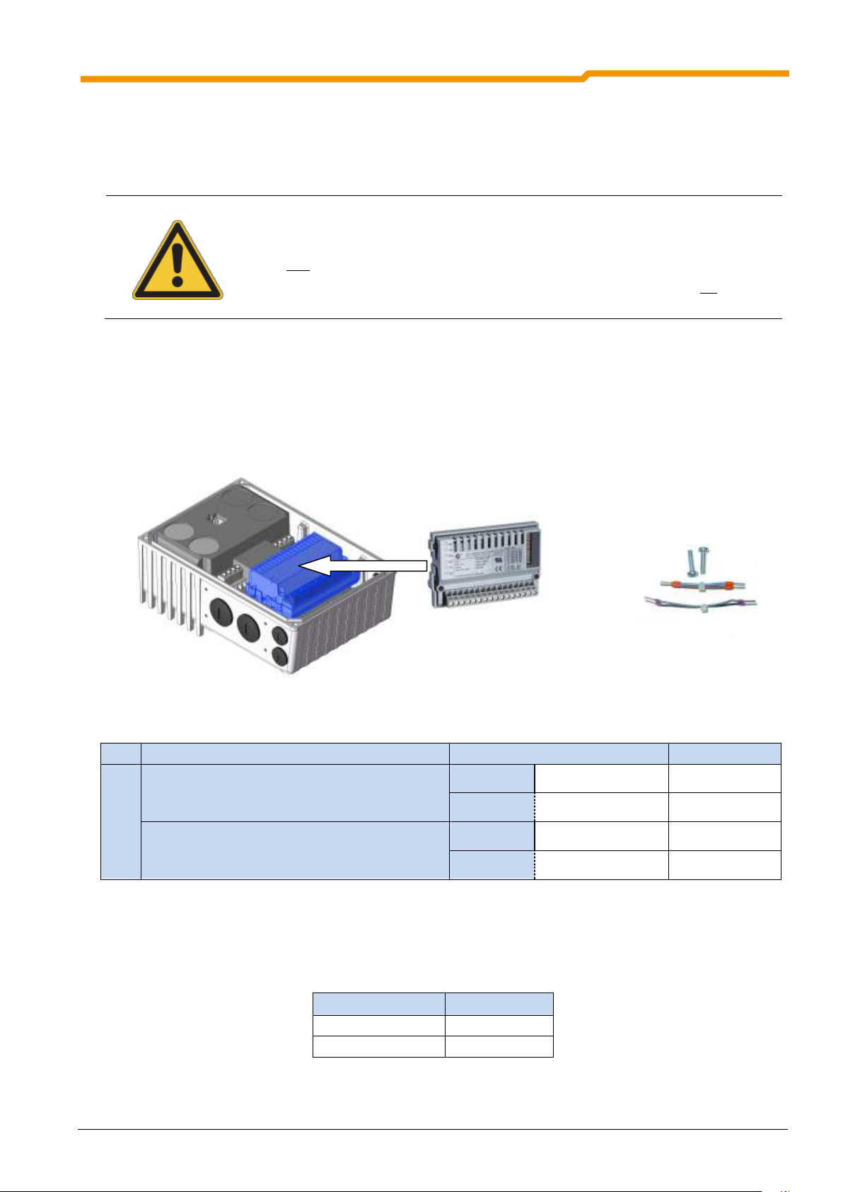
WARNING
Installation must be carried out by qualified personnel only, paying particular attention to
safety and warning instructions.
Modules must not be inserted or removed unless the device is free of voltage. The slots
may only be used for the intended modules.
Installation of the SK CU4-… customer unit remote from the frequency inverter is not permitted.
This must be mounted directly in the housing box of the SK 1x0E.
Function
Terminal label
Cable colour
Field bus / IOE
Power supply (24V DC)
(between the frequency inverter and the customer unit)
44
24V
brown
40
GND / 0V
blue
System bus
77
SYS H (+)
black
78
SYS L (-)
grey
Connection unit
Document
SK TI4-TU-BUS
TI 275280000
SK TI4-TU-BUS-C
TI 275280500
Similar to illustration
Similar to illustration
3.2 Mounting of optional module
3.2.1 Installation of internal customer units SK CU4-…
The customer interfaces are installed directly within the housing box of the frequency inverter, behind the
control terminal bar. The customer interface is fastened with the two screws which are included in the
delivery. Only one Customer Unit per device is possible!
The pre-assembled cables for connection to the frequency inverter are also included in the bag enclosed
with the customer unit. Connections are made according to the following table:
The bus modules require a 24 V supply voltage.
SK 1x0E with integrated technology unit SK CU4-… Customer unit SK CU4-… Bag enclosed with internal customer unit
Allocation of the cable sets (bag enclosed with the customer unit)
3 Options
3.2.2 Installation of external technology units SK TU4-…
A detailed description can be found in the technical information or data sheet (TI ...) for the relevant
connection unit.
BU 0180 GB-0914 Pre-series version 53
Page 54

SK 180E Manual for frequency inverters
Module
SK CU4-POT
Function
SK 1x0E
Pin
Color
FI
1
brown
24V-supply voltage
43
Rotary switch
L - OFF - R
2
black
Enable R (e.g. DIN1)
21
3
white
Enable L (e.g. DIN2)
22
4
white
Access to AIN +
14
Potentiometer
10kΩ
5
brown
Reference voltage 10V
11
6
blue
Analog ground AGND
12
Frequency inverter
SK 1x0E-...
Control terminal bar
12(40)
14
11
.
.
43
.
.
21
22
.
SK CU4-POT
Potentio-
meter
0-10
R/0/L
Switch
L1 - L2/N - L3
230/400V
24V=
10V=
(A)GND
0-10V
R
L
1/3~ 230/400V + PE
(br)
(br)
(bk)
(wh)
(br)
(wh)
(bl)
3.3 Details of internal Customer Units SK CU4-…
3.3.1 Potentiometer adapter, SK CU4-POT
The digital signals R and L can be directly applied to the corresponding digital inputs 1 and 2 or 3 of the
frequency inverter.
The potentiometer (0-10V) can be evaluated via the analog inputs of the frequency inverter, or via an
optional I/O extension.
SK CU4-POT connections
54 Pre-series version BU 0180 GB-0914
Page 55

3.3.2 Electronic brake rectifier, SK CU4-MBR
Brake coil voltage
Mains voltage
Contact No.
205 V DC
230 V AC
L1B + N/L2
180 V DC
400 V AC
L1E + N/L2
205 V DC
460 V AC or 480V AC
L1E + N/L2
L2 /
N
L2 /
N
L1
B
L1
B
L1
E
L1
E
79 80
B5
C5
40
44
L1 380…480 V~
L2 / N
Mains voltage
Connection of the 24 V power
supply from the SK 1x0E
Connection of DC brake coil
Potential level: 24 V DC
Potential level: = Brake
24V
GND / 0V
Connection to the terminal bar
of the SK CU4-MBR-…
DIN
MB+
MB-
(Select connection according to voltage)
…
1
40
43
SK CU4-
SK 1x0E-
Digital control in the SK CU4 via
DO from the SK 1x0E
DO
Feedback of operating status of the
brake from the DO of SK CU4
L1 200…240 V~
Potential level: = Brake
Potential level: ~ Mains
Similar to illustration
The electronic brake rectifier SK CU4-MBR is used to control electromechanical brakes with a coil voltage of
180V DC and 205V DC (for sizes 5Nm to 40Nm via the frequency inverter or its accessories (SK xU4-IOE).
Monitoring of the current in the brake coil is integrated into the
SK CU4-MBR module.
• Mains voltage 230 V~ and 400 V~
• +24 V control voltage
• 1x Digital input (control)
• 1x Digital output (feedback)
• Brake connection (DC)
• Max. permissible permanent relay current 0.5 A
• Interference suppression class C2
• Permissible cycle time (1 switching cycle =1xON/1xOFF):
Brake 5…100 Nm: ≥ 0.5 s
The terminal bar of the customer unit SK CU4-MBR-… is divided into three potential levels.
3 Options
According to the mains voltage, the mains cable must be connected to L1E (380 V~ … 480 V~) or L1B
(200 V~ … 275 V~) and L2/N. The brake connection is made to Terminals 79/80. Assignment of the brakes
is made according to the following table. The module must be supplied with 24 V DC. Control is via Terminal
C5 by means of a digital output of the frequency inverter which is parameterised to the function {1} "External
brake". Feedback of the operating status of the brake (current/no current supplied to the brake) is via
Terminal B5 of the module.
BU 0180 GB-0914 Pre-series version 55
Page 56

SK 180E Manual for frequency inverters
Terminal/
Designation
Function
Data
Description / wiring suggestion
Parameter
44 24V
24V supply
24 V DC ± 25%
50 … 500mA (according
to load on the digital
output)
Supply voltage connection for the
module
-
40 GND /0V
GND
Reference potential
-
C5 DIN
Digital input
Current consumption with
30 V DC: 13 mA
24 V DC: 10 mA
15 V DC: 5.5 mA
Switching thresholds
ON: > approx. 8.5 V
OFF: < approx. 7.5 V
Digital input for DC brake switching
-
B5 DOUT
Digital output
15 … 30 V, 200 mA, SPScompatible according to
EN61131-2
Low: 0 V / <30 mA
No current through brake
High: 24V / >70mA
Current through brake
Reporting of current status of the
mechanical brake
-
Potential isolation
79 MB+
Brake control
Voltage:
Mains brake
230 V~ 205 V=
400 V~ 180 V=
460/480 V~ 205 V=
Current: max. 0.5 A
The module SK CU4-MBR
generates an output voltage on
Terminals MB+/MB- for control of
an electromechanical brake. This
depends on the supply voltage and
the connection of the supply cable
to the one-way (L1E) or bridge
rectification (L1B) of the module.
The assignment of the correct
brake coil voltage must be taken
into account in the selection.
(NOTE: this function is identical to
P434=1)
P107*,
P114*,
P505
80 MB-
Brake control
Potential isolation
L1E
Mains connection
1st phase
Supply voltage L1:
380V … 480 V ± 10% AC,
max. 10 A
Mains connection for one-way
rectification.
-
L1E
-
L1B
Mains connection
1. Phase
Supply voltage L1:
200V … 240 V ± 10% AC,
max. 10 A
Mains connection for bridge
rectification.
-
L1B
-
L2 / N
Mains connection
2. Phase
Connection of 2nd phase for mains
connection L1E or L1B.
-
L2 / N
-
* Recommended setting (P107/P114) for NORD brakes: BRE5, 10, 40: 0.02s / BRE 20, 60 : 0.03s
Control connection details
56 Pre-series version BU 0180 GB-0914
Page 57
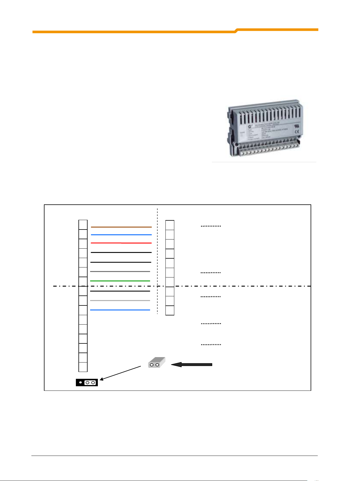
3.3.3 Setpoint converter, SK CU4-REL
R21
R22 R24 R11
R12
R14
40
C2
C1
118 117
116 114
111
112
44
Relay 1
Connection of the 24V power
supply from the SK 1x0E
AOUT connection of the
SK CU4 to AIN of the SK 1x0E
24V
AGND / 0V
Connection to the terminal bar
of the SK CU4-REL-…
10V REF.
DI1
AOUT1
R11 / R14 = NO
R11 / R12 = NC
SK CU4-
SK 1x0E-
Digital control in the SK CU4 via
DO from the SK 1x0E
AIN1
Connection for bipolar analog signals
Potential level: Analog
Potential level: Digital / Relay
…
11
12*
43 1 16
14 … 40
3
AIN2
AOUT2
DI2
Relay 2
R21 / R24 = NO
R21 / R22 = NC
* Terminal 12 or Terminal 40
GND / 0V
Potential level jumper connections :
Illustration: Potential levels with analog and digital
connection
Similar to illustration
The analog inputs of SK 1x0 E series frequency inverters and the optional mains units SK xU4-24V can only
process unipolar setpoint values referenced to GND (0/2 … 10 V; 0/4 … 20 mA). If a bipolar setpoint
(10V … + 10 V) is available, this must be converted to a 0 … 10 V signal by means of an SK CU4-REL setpoint
converter.
Two coupling relays are integrated into the module. These are controlled via the digital outputs of the
frequency inverter and can be used as openers or closers according to their connection.
• +24V control voltage
• 2x Analog inputs (-10 … +10 V)
• 2x digital inputs
• 2x Analog outputs (0 … 10 V) only for transfer to the
frequency inverter
• 2x Relay outputs (each configured as changeovers)
• Max. permissible continuous relay current: 1000 mA (≤30 V DC)
• incl. cable set
The terminal bar of the customer unit SK CU4-REL-… is divided into two potential levels (potential
separation max. 50 V DC). On delivery, these are connected together with a plug-in jumper.
3 Options
The bipolar analog signals must be connected to input terminals 114 or 116. Via the analog outputs
(Terminal 117 or 118) the signals which are transformed to 0...10V can be accessed and transferred to the
frequency inverter for further processing. In order to ensure the function of the analog signal converter, the
10V DC reference voltage of the frequency inverter must be wired to the reference potential of the setpoint
source(s) of the SK CU4-REL
Up to 2 digital signals can be transferred to the coupling relays from the frequency inverter. Regardless of
the wiring, both relays each provide the possibility of accessing an opening (NC) or a closing (NO) signal.
The module must be supplied with 24V DC.
BU 0180 GB-0914 Pre-series version 57
Page 58

SK 180E Manual for frequency inverters
Terminal/
Designation
Function
Data
Description / wiring suggestion
Parameter
44 24V
24V supply
24V DC ±25%
20 mA
Connection of the supply voltage
for the module and the reference
potential of the analog signals
112 AGND / 0V
Reference potential
for analog signals
111 10V REF
+10V
Reference voltage
+10V, 5 mA
Connection of reference voltage
from frequency inverter
114 AIN1
Analog input 1
U= -10 … +10 V, Ri=2 MΩ
Resolution 10Bit
Signal IN
Signal OUT
Terminal
Value
Terminal
Value
114
-10V
117
+10V
114
+10V
117
0V
116
-10V
118
+10V
116
+10V
118
0V
The conversion of the analog
signals is inverted.
Assignment of the functions of the
analog input signals is made via
parameter P400[...] of the
frequency inverter.
116 AIN2
Analog input 2
117 AOUT1
Analog output 1
Resolution: 10Bit
Precision: 0.25 V
Load capacity with signal:
0…10 V: ≤ 10 mA
118 AOUT2
Analog output 2
Potential isolation
C1 DIN1
Digital input 1
Relay input:
Low: 0-5V (2.8kOhm)
High: 18-30V (1.6kOhm)
Reaction time max. 7ms
Assignment of the functions of the
analog output signals is made via
parameter P434[...] of the
frequency inverter.
C2 DIN2
Digital input 2
40 GND / 0V
Reference potential
for digital signals
R14 R1 NO
Relay 1.1
Normally closed
contact
Relay input:
Low: 0-5 V (2.8 kOhm)
High: 18-30 V (1.6 kOhm)
Reaction time max. 7 ms
Mechanical
lifetime:
1x10⁸ (1 billion) OPS
(Operations)
Electrical:
3x10⁵ (3 million) OPS
(Operations)
Relay (changeover) with function:
Closer: R11 / R14
Opener: R11 / R12
R12 R1 NC
Relay 1.2
Normally opened
contact
R11
Relay 1.3
Common contact
R24 R2 NO
Relay 2.1
Normally closed
contact
Relay (changeover) with function:
Closer: R21 / R24
Opener: R21 / R22
R22 R2 NC
Relay 2.2
Normally opened
contact
R21
Relay 2.3
Common contact
To separate the two potential levels, the jumper (at the start of the series terminal) must be plugged in
differently or pulled out entirely.
Control connection details
58 Pre-series version BU 0180 GB-0914
Page 59

3.3.4 Direction selection switch and potentiometer SK TIE4-SWT and SK TIE4-POT
Module
SK TIE4-SWT
Function
SK 1x0E
Color
FI
brown
24 V-supply voltage
43
Rotary switch
L - OFF - R
black
Enable R (e.g. DIN1)
21
white
Enable L (e.g. DIN2)
22
Module
SK TIE4-POT
white
Access to AIN +
14
Potentiometer
10kΩ
brown
Reference voltage 10 V
11
blue
Analog ground AGND
12
The digital signals R and L of the direction selector switch SK TIE4-SWT (Part No.: 275274701) can be
applied directly to the corresponding digital inputs 1 and 2 of the frequency inverter.
The potentiometer (0-10 V) SK TIE4-POT (Part No.: 275274700) can be evaluated via the analog inputs of
the frequency inverter or the I/O extension. Each of the modules (control element) is supplied with a
pre-assembled cable. This must be plugged into the connection plug of the relevant module. The open ends
of the cable set must be wired to the terminal bar of the frequency inverter according to the table.
Both modules have protection class IP66.
3 Options
For examples of connections to the frequency inverter, please refer to Section 3.3.1.
Installation
Installation of the potentiometer (SK TIE4-POT) is possible on a 4 M25 versions of the device. In contrast,
installation of the switch (SK TIE-SWT) is only possible on the M25 holes 3BL and 3 BR; for Size 2 also
on 3AL:
BU 0180 GB-0914 Pre-series version 59
Page 60

SK 180E Manual for frequency inverters
SK TI4-TU-BUS SK TI4-TU-MSW
Feature
Bus modules
Maintenance switch
Designation of connection unit
SK TI4-TU-BUS
SK TI4-TU-MSW
Designation of Technology Units
SK TU4-PBR-…
…CAO… / …DEV… / …EIP…/ …ECT… /
…PNT… / …POL… / …IOE…
SK TU4-MSW-…
24V - supply required!
Yes
No
24V supply integrated
No
No
System bus connection
Yes
No
Motor mounting possible
Yes
Yes
Mounting near to motor possible
Yes, with wall-mounting kit
SK TIE4-WMK-TU
Yes, with wall-mounting kit
SK TIE4-WMK-TU
NOTE
Connection terminals with identical designations are first connected internally, if the
technology unit has been mounted on the corresponding connection unit. Because of this,
when removing a BUS module from the connection unit, the relevant BUS system (e.g.
Profibus) is disconnected.
3.4 Details of external Technology Units SK TU4-…
The technology units are divided into two different groups. The BUS group contains all the bus modules and
the I/O extension. These are connected to the SK 1x0E via the system bus.
The second group includes other technology units, e.g. the maintenance switch SK TU4-MSW.
Due to the very different functions, the device groups require different connection units.
3.4.1 Connection unit SK TI4-TU-BUS / -MSW
All connections are made via the connection unit. This includes customer control of the
module and connection of the module to the frequency inverter. In parallel with this, the
analog and digital inputs and outputs of the frequency inverter also remain available.
The relevant Technology Unit is attached to the appropriate Adapter Unit with screws.
Installation information can be found in Section 3.2.2.
60 Pre-series version BU 0180 GB-0914
Page 61

Terminal/
Designation
Function
Data
Description /
wiring suggestion
Parameter
Supply (Mains input)
L1
Mains connection
1st phase
I
nom
= 16A
Mains connection, according to
network
1~100 – 240 V to L1 and L2
or
3~ 200 – 480 V to L1, L2 and L3
-
L2
Mains connection
2nd phase or "N"
-
L3
Mains connection
3rd phase
-
PE
PE, Earth
-
Output
L1
Mains connection
1st phase
I
nom
= 16A
Frequency inverter connection,
according to network
1~100 – 240 V to L1 and L2
or
3~ 200 – 480 V to L1, L2 and L3
-
L2
Mains connection
2nd phase or "N"
-
L3
Mains connection
3rd phase
-
PE
PE, Earth
-
Connection to the terminal bar
of the SK TI4-TU-MSW
Supply (mains)
Output (frequency inverter)
3.4.1.1 Connections of the SK TI4-TU-BUS
The precise connections of the 36 spring-loaded terminals depend on the Technology Unit used. Details can
be found in the relevant documents for the bus system.
3.4.1.2 Connections of the SK TI4-TU-MSW
Connection of the incoming and outgoing mains cable (incl. PE) is made on the relevant terminal blocks as
shown in the illustration. With single phase mains cables the conducting phase must be connected to L1
and the neutral conductor to L2.
3 Options
Control connection details
BU 0180 GB-0914 Pre-series version 61
Page 62

SK 180E Manual for frequency inverters
3.4.2 Maintenance switch, SK TU4-MSW-…
The maintenance switch can be looped into the mains supply cable of the frequency inverter in order to
interrupt the voltage supply to a connected frequency inverter. The maintenance switch has a 3-pole design
and can therefore be used for 1 - 3 phase AC supply networks up to 480 V U
• Maintenance switch for AC supply networks
1~100-240 V or 3~ 200-480 V, I
nom
16A
rms
• Status LEDs = L1, L2, L3
The SK TU4-MSW-… maintenance switch is operated in
combination with an SK TI4-TU-MSW connection unit.
Details of the control connections can be found in the
connection unit section (Section 3.4.1.2).
The front-mounted LEDs L1 ... L3 indicate the presence of a
voltage at the output side of the switch.
Nom
.
62 Pre-series version BU 0180 GB-0914
Page 63

4 Display and control
LED
Name
Colour
Description
Signal status
Meaning
DS
dual
red/green
Device status
off Frequency inverter not ready for operation,
no control voltage
green on
Frequency inverter ready for operation
green
flashing
0.5 Hz
Frequency inverter ready for switch-on
4 Hz
Frequency inverter is in switch-on block
red/green
4 Hz
Warning
Alternating
1…25 Hz
Degree of overload of switched-on FI
green on +
red flashing
Frequency inverter not ready for operation,
red flashing
Error, flashing frequency → Error number
AS-I
dual
AS-i status
off No voltage to the AS-i module (PWR)
red/green
green
Normal operation
red No exchange of data
Slave Address = 0 / Slave not in LPS /
Slave with incorrect IO/ID / Master in
STOP mode / Reset active
alternately
flashing
red / green
Peripheral error
Diagnostic connection
Status LED
LED for AS interface
(SK 190E)
Diagnostic interface
4 Displays and control
By the use of various modules for display, control and parameterisation, the frequency inverter can be easily
adapted to various requirements.
Alphanumeric display and control modules (Section 4.2) can be used for simple commissioning. For more
complex tasks, connection to a PC system and the use of NORD CON parameterisation software is
available.
As supplied, without additional options, the diagnostic LED is externally visible. This indicates the actual
status of the device. In contrast, the AS-i LED (SK 190E) is only visible if the device is open.
4.1 Diagnostic LEDs on the Frequency Inverter
The frequency inverter generates operating status messages. These messages (warnings, faults, switching
statuses, measurement data) can be displayed with parameterisation tools (e.g. ParameterBox - see
Section 4.2) (Parameter group P7xx). To a limited extent, the messages are also indicated via the
diagnostic and status LEDs.
BU 0180 GB-0914 Pre-series version 63
Page 64

SK 180E Manual for frequency inverters
Module
Description
Data
SimpleBox
Handheld
SK CSX-3H
Used (exclusively) for commissioning,
parameterisation, configuration and control
of the frequency inverter. Storage of the
parameters is not possible.
Manual BU 0040 (www.nord.com)
4-digit, 7-segment LED display
IP20
RJ12-RJ12 cable ((for connection to FI)
Part. No. 275281013
ParameterBox
Handheld
SK PAR-3H
Used for commissioning, parameterisation,
configuration and control of the frequency
inverter and its options (SK xU4-…). Saving
of parameters is possible.
Manual BU 0040 (www.nord.com)
4 digit back-lit LCD display, keyboard
Stores up to 5 complete FI data sets
IP20
RJ12-RJ12 cable (for connection to FI / Option)
USB-Cable (For connection to PC)
Part. No. 275281014
Mounting of the control unit on the frequency inverter:
Installation of the control unit is performed as follows:
1. Remove the blind plug from the cable gland.
2. Connect the RJ12-RJ12 cable between the control unit and
the frequency inverter.
3. After commissioning the blind plug must be replaced and
care must be taken that there is a tight seal before regular
operation is started.
4. As long as the cable gland is open, take care that no dirt or
moisture enters the device.
4.2 Overview of external control devices
All parameters can be easily accessed for reading or editing by means of an optional SimpleBox or
ParameterBox. The changed parameter data are stored in the non-volatile EEPROM memory.
In addition, up to 5 complete frequency inverter data sets can be saved in the ParameterBox and then
recalled.
The connection between the SimpleBox or ParameterBox and the SK 1x0E is made with an RJ12-RJ12
cable.
NOTE: For use on the SK 1x0E the ParameterBox SK PAR-3H must have at least the software
version 4.4 R2.
64 Pre-series version BU 0180 GB-0914
Page 65
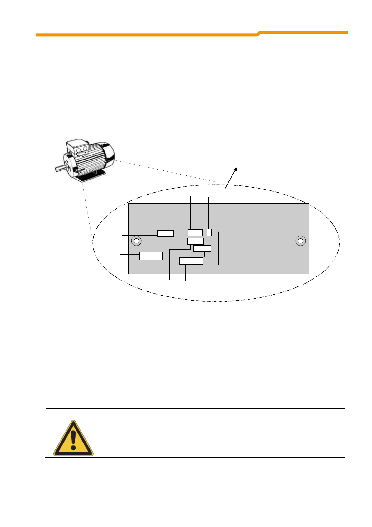
5 Commissioning
3~ Mot
IEC 56
IM B3
cos 0.74
cos 0.74
IP55
Rot. KL 16
Th.Cl.F
EN60034
60 Hz
460 V Y
5.2 A
2,5 kW
1765 /min
1440 /min
P206
P201
P204
P203
P202
P200
9,0 / 5.2 A
50 Hz
2.2 kW
P207
P200 Motor list:
0 = no change 10 = 0.37 kW 230 V
1 = no motor 11 = 0.50 PS 230 V
2 = 0.12 kW 230 V 12 = 0.37 kW 400 V
3 = 0.16 PS 230 V 13 = 0.50 PS 460 V
4 = 0.18 KW 230 V 14 = 0.55 kW 230 V
5 = 0.25 PS 230 V 15 = 0.75 PS 230 V
6 = 0.25 kW 230 V 16 = 0.55 kW 400 V
7 = 0.33 PS 230 V 17 = 0.75 PS 460 V
8 = 0.25 kW 400 V 18 = 0.75 kW 230 V
9 = 0.33 PS 460 V ....
230 / 400 V /Y
ATTENTION
DANGER TO LIFE!
The frequency inverter is not equipped with a line main switch and is therefore always live when
connected to the power supply. Live voltages may therefore be connected to a connected motor
at standstill.
5 Commissioning
5.1 Factory settings
All frequency inverters supplied by Getriebebau NORD are pre-programmed with the default setting for
standard applications with 4-pole standard motors (same voltage and power). For use with motors with
other powers or number of poles, the data from the rating plate of the motor must be input into the
parameters P201...P207 under the menu item >Motor data<.
NOTE: All motor data can be pre-set using parameter P200. After use of this function, this parameter
is reset to 0 = no change! The data is loaded automatically into parameters P201...P209 –
and can be compared again with the data on the motor rating plate.
RECOMMENDATION: For the correct operation of the drive unit, it is necessary to input the motor data
(rating plate) as precisely as possible. In particular, an automatic stator resistance
measurement using parameter P220 is recommended.
In order to automatically determine the stator resistance, set P220 = 1 and confirm
by pressing "OK". The value calculated for the line resistance (dependent upon
P207) will be saved in P208.
5.2 Commissioning of frequency inverters
The frequency inverter can be commissioned by adjustments to the parameters with software, using
ParameterBox (SK CSX-3H or SK PAR-3H) or the PC-based software NORD CON. Here, the
parameterised data is stored in the internal EEPROM.
BU 0180 GB-0914 Pre-series version 65
Page 66

SK 180E Manual for frequency inverters
NOTE
For commissioning standard applications, a limited number of the frequency inverter inputs and
outputs (physical and I/O bits) have predefined functions. These settings may need to be
changed (Parameters (P420), (P434), (P480), (P481)).
Parameter group
Parameter numbers
Functions
Comments
Motor data
P201 … P207, (P208)
Data on motor rating plate
P220, Function 1
Measure stator resistance
Value is written to P208
alternatively
P200
Motor data list
Selection of a 4-pole standard
motor from a list
alternatively
P220, Function 2
Motor identification
Complete measurement of a
connected motor
Prerequisite: motor no more
than 3 power levels less than
the frequency inverter
Basic parameters
P102 … P105
Ramp times and frequency
limits
Control terminals
P400, P420
Analog and digital inputs
NOTE
Prior to commissioning, it should be ensured that the frequency inverter is in its default setting
(P523). DIP switches S2 should remain in the "off" setting. DIP switches S2 have priority over
the parameters P509, P514 and P515.
5.2.1 Connection
After mounting the frequency inverter on the motor or the wall mounting kit, the mains and motor cables
must be connected to the relevant terminals (PE, L1, N (/L2, L3) and U, V, W) (See sections 2.7 and 2.8).
In principle, the frequency inverter can be operated in this configuration. (See Section 5.2.3)
5.2.2 Configuration
Changes to individual parameters are usually necessary for operation.
5.2.2.1 Parameterisation
The use of a ParameterBox (SK CSX-3H / SK PAR) or NORD CON software is necessary to change the
parameters.
66 Pre-series version BU 0180 GB-0914
Page 67

5 Commissioning
No.
Bit DIP switch (S2)
2/1
2
1/0
ADR
System bus
address/ baud rate
DIP-No
3 2 0 0 Corresponding to P515 and P514 [32, 250kBaud]
0 1 Address 34, 250kBaud
1 0 Address 36, 250kBaud
1 1 Address 38, 250kBaud
3
2
2
BUS
Source control
word and setpoint
value
0
Corresponding to P509 and P510 [1] [2]
1
System bus ( P509=3 and P510=3)
NOTE
FACTORY SETTING, AS DELIVERED!
As delivered, all DIP switches are in the "0" ("off") position.
No.
Bit DIP switch (S1)
3
2
2
U / I AIN2
Voltage/current
0
Analog input 2 in voltage mode 0...10 V
1
Analog input 2 in current mode 0/4...20 mA
2
2
1
U / I AIN1
Voltage/current
0
Analog input 1 in voltage mode 0...10 V
1
Analog input 1 in current mode 0/4...20 mA
1
2
0
SYS
Burden resistor
0
Burden resistor switched off
1
Burden resistor activated
S2
S1
AIN2
AIN1
SYS
ADR2
ADR1
BUS
5.2.2.2 DIP switch configuration of the inverter
The analog inputs in the frequency inverter are suitable for current and voltage setpoints. For correct
processing of current setpoints (0-20mA / 4-20mA) the relevant DIP switch (S1) must be set for current
signals ("ON").
Adjustment to fail-safe signals in case of cable breaks (2-10V/4-20mA) is made via parameters 402 and 403.
A second DIP switch (S2) is also available, via which the system bus address can be specified or the
system bus can be activated. This has priority over the parameters P509, P514 and P515.
BU 0180 GB-0914 Pre-series version 67
Page 68

SK 180E Manual for frequency inverters
Function
Setting
Setpoint
External 10 kOhm potentiometer
Controller enable
External switch S1
1. The motor data P201-P207 must be set according to the rating plate.
2. The motor stator resistance P208 is determined at 20°C with P220 = 1.
3. Function analog input 2, P400 [-02] = 30 (Motor temperature)
4. The mode analog input 2 P401 [-06] = 1 (negative temperatures are
also measured)
Adjustment of analog input 2: P402 [-06] = 1.54V and
P403 [-06] = 2.64V (with RV= 2.7 kOhm)
5. Adjust time constants: P404 [-02] = 400ms
(Filter time constant is maximum)
6. Motor temperature control (display): P739 [-03]
* If necessary, also Terminal 40
Frequency inverter
SK 1x0E-...
Control terminal bar
12/40
14
11
.
43
.
21
22
.
38
39
L1 - L2/N - L3
230/400 V
1/3~ 230/400V + PE
Switch S1
Motor PTC
Potentiometer
10kOhm
5.2.3 Commissioning examples
All devices can be operated in the condition in which they are delivered. The standard motor data of a
4-pole IE1 standard asynchronous motor of the same power are parameterised. The PTC input must be
bypassed, if a motor with PTC is not available. Parameter (P428) must be changed if an automatic start-up
with "Mains On" is required.
5.2.3.1 Minimal configuration
The frequency inverter provides all the necessary low voltages (24V DC / 10V DC).
Minimal configuration with options
In order to implement completely autonomous operation (i.e. independent of control cables etc.) a
potentiometer unit (SK CU4-POT) is required. In this way, the required speed and direction control can be
achieved with only a single mains cable (single phase or three-phase, according to the version) (see
connection example in Section 3.3.1).
5.3 KTY84-130 connection
The current vector control of the SK 1x0E series can be further optimised by the use of a KTY84-130
temperature sensor (R
the highest precision of regulation by the frequency inverter and the associated optimum speed precision of
the motor is achieved at all times. As the temperature measurement starts immediately after the (mains)
switch-on of the frequency inverter, the frequency inverter provides immediate optimum control, even if the
motor has a considerably increased temperature after an intermediate "Mains off / Mains on" of the
frequency inverter.
Connection examples:
SK 1x0E
Connection of a KTY-84 to either of the two analog inputs of the SK 1x0E is possible. In the following examples,
analog input 2 of the frequency inverter is used.
68 Pre-series version BU 0180 GB-0914
th(0°C)
=500, R
=1000). By continuous measurement of the motor temperature,
th(100°C)
Page 69

5 Commissioning
NOTE
To determine the stator resistance of the motor, the temperature range 15 … 25°C should not
be exceeded.
Excess temperature of the motor is also monitored and at 155°C (switching threshold for the
thermistor) causes the drive unit to shut down with error message E002.
SK CU4-IOE / SK TU4-IOE-…
Connection of a KTY-84 to either of the two analog inputs of the relevant option is possible. In the following
examples, analog input 2 of the particular optional module is used.
SK CU4-IOE SK TU4-IOE
(Illustration shows a section of the terminal blocks)
Parameter settings (Analog input 2)
The following parameters must be set for the function of the KTY84-130.
1. The motor data P201-P207 must be set according to the rating plate.
2. The motor stator resistance P208 is determined at 20°C with P220 = 1.
3. Function analog input 2, P400 [-04] = 30 (Motor temperature)
4. The mode for analog input 2, P401 [-02] = 1 (negative temperatures are also measured)
5. Adjustment of analog input 2: P402 [-02] = 1.54V and P403 [-02] = 2.64V (with RV= 2.7 kOhm)
6. Adjust time constants: P161 [-02] = 400ms (Filter time constant is at a maximum)
Parameter (P161) is a module parameter. This cannot be set on the frequency inverter, but rather directly on the I/O-module.
Communication is carried out e.g. via the direct connection of a ParameterBox to the RS232 interface of the module or by the
connection of the frequency inverter via the system bus. (Parameter (P1101) object selection → … )
7. Motor temperature control (display): P739 [-03]
BU 0180 GB-0914 Pre-series version 69
Page 70

SK 180E Manual for frequency inverters
Permissible
Standard slave 1 (Address 6)
A/B-Slave 1: (Address 7A)
A/B-Slave 2: (Address 7B)
Standard slave 2 (Address 8)
Not permissible
Standard slave 1 (Address 6)
Standard slave 2: (Address 7)
A/B-Slave 1: (Address 7B)
Standard slave 3 (Address 8)
5.4 AS interface (only SK 190E)
5.4.1 The bus system
The ActuatorSensor Interface (AS-Interface) is a bus system for the lower field bus level. The transmission
principle is a single master system with cyclical polling. A maximum of 31 slaves (or 62 A/B slaves in the
extended address region) can be operated on an up to 100m long unshielded two-wire cable in any network
structure (tree/line/star). For the AS-interface, since the Complete Specification V2.1, a differentiation has
been made between Standard Slaves and A/B Slaves. This version includes the doubling of the number of
slaves to 62. This is done by the double-assignment of addresses 1-31 and their designation as "A Slave"
and "B Slave". A/B Slaves are designated by the ID code A, and therefore can be uniquely identified by the
Master.
The SK 190E frequency inverter is an A/B slave, which corresponds to slave profile S-7.A. They can be
administered by masters whose profile at least corresponds to class M4.
In contrast to devices with the profile S-7.0 devices with the profile S-7.A use the extended address range.
Devices with slave profiles S-7.0 and S-7.A can be jointly operated within an ASi network as of version 2.1
(Master profile M4) with observance of the allocation of addresses (see example).
The yellow AS interface cable supplies data and energy. Addressing is implemented via the master, which
can also provide other management functions, or via a separate addressing device. The transfer of the 4 Bit
reference data (in each direction) is performed with effective error protection for standard slaves with a
maximum cycle time of 5ms. Due to the correspondingly higher number of participants, for A/B slaves the
cycle time (max. 10ms) is doubled for data which is sent from the slave to the master. Extended addressing
procedures for the transmission of data to the slave also cause an additional doubling of the cycle time to
max. 21ms.
The bus system is completely defined in the AS-Interface Complete Specification and is standardised as per
EN 50295, IEC62026.
5.4.2 Features
The SK 190E frequency inverter versions provide an integrated AS interface as standard. Therefore, these
devices can be directly integrated into an AS interface network. Only the adaptation of various frequency
inverter functions, addressing and the correct connection of the power supply, BUS, sensor and actuator
cables needs to be carried out.
Features
Electrically isolated bus interface
Status display (1 LED) inside the device (can be viewed with the cover open)
Configuration by parameterisation
Slave profile S-7.A (4I / 4O), (A/B Slave)
Connection of the frequency inverter via the terminal bar, optionally via M12 flanged plug connector
Up to 31 standard slave (or 62 A/B slaves in the extended address region) on one bus conductor
Cycle time ≤ 5 ms / 10 ms (A/B)
Address as delivered = 0
Max. current consumption: 25 mA
The factory setting of the frequency inverter enables the immediate availability of common AS-i basic
functions. These functions can be adapted by parameterisation.
70 Pre-series version BU 0180 GB-0914
Page 71

5 Commissioning
NOTE
It is essential that the PE connection of the AS interface mains unit (if present) is earthed.
The brown ASi+ and the blue ASi- wire from of the AS interface cable must not be earthed.
AS Interface
Master
AS Interface
mains unit
Sensors
Actuators
Sensors
Actuators
AS Interface
Slave (SK 190E)
AS Interface
Slave (SK 190E)
AS-Interface
yellow cable
Control unit /
Automation device
observe max.
power load
5.4.3 Bus structure and topology
The AS interface network can be set up in any desired form. Linear, star, ring and tree structures are
possible. An existing network can be expanded by further slaves at any time. Up to 31 standard slaves (i.e.
a maximum of 124 binary sensors and 124 binary actuators) or 62 A/B slaves (i.e. a maximum of 248 binary
sensors and 248 binary actuators) can be connected to an AS interface network or an AS interface master.
Each AS interface slave has its own address (1 to 31 (or 1A … 31A, 1B … 31B)), which is assigned to the
slave with the aid of an addressing device, or is transferred to the slave by means of a command from the
AS interface master. Each slave address may only be assigned once.
Normally the AS interface master is a component or module of the control unit and forms the interface
between the control unit and the connected slave. An AS-i master communicates independently and
exchanges data with the connected AS-i slave options. Normal power units must not be used in the AS
interface network. For each AS interface connector, only a special AS interface power units may be used for
the power supply. This AS interface power supply is directly connected to the yellow standard cable (ASI+
and ASI- cable) and should be positioned as close as possible to the AS-i master in order to keep the
voltage drop small.
BU 0180 GB-0914 Pre-series version 71
Page 72

SK 180E Manual for frequency inverters
LED (dual)
Meaning
OFF
No AS interface voltage to the module (PWR)
Connections to terminals 84 and 85 exchanged.
green ON
Normal operation (AS interface active)
red ON
no exchange of data
Slave address = 0
Slave not in LPS
Slave with incorrect IO/ID
Master in STOP mode
Reset active
alternately
flashing
red / green
Peripheral error
FI control unit does not start (AS-i voltage too low,
control unit faulty)
85 84
5.4.4 Commissioning of the AS Interface
Connection
Connection of the AS interface cable is made via terminals 85/85 of the terminal block and can optionally be
made to an appropriately labelled M12 flange plug contact (yellow) Details of the connection terminals are
explained in Section 2.8.2.
Signal status LED / ASi-specific display
With these devices, the status of the ASi interface is indicated by the dual colour LEDAS-i.
Control voltage - frequency inverter supply
The yellow ASi cable supplies the AS interface with the necessary control voltage. The control section of the
frequency inverter is not supplied from the AS interface voltage.
Configuration
The most important functions are assigned via the arrays [-01] … [-04] of parameter (P480) and (P481).
Addressing
In order to use a frequency inverter in an ASi network, this must be assigned with a unique address (1-31).
The FI is set to address 1 as the factory setting, and can therefore be identified as a "new device" by the
AS-i master (prerequisite for the automatic address assignment by the master).
In many other cases, addressing is carried out by means of a normal addressing device for AS-i slaves.
The following should be noted:
72 Pre-series version BU 0180 GB-0914
Page 73
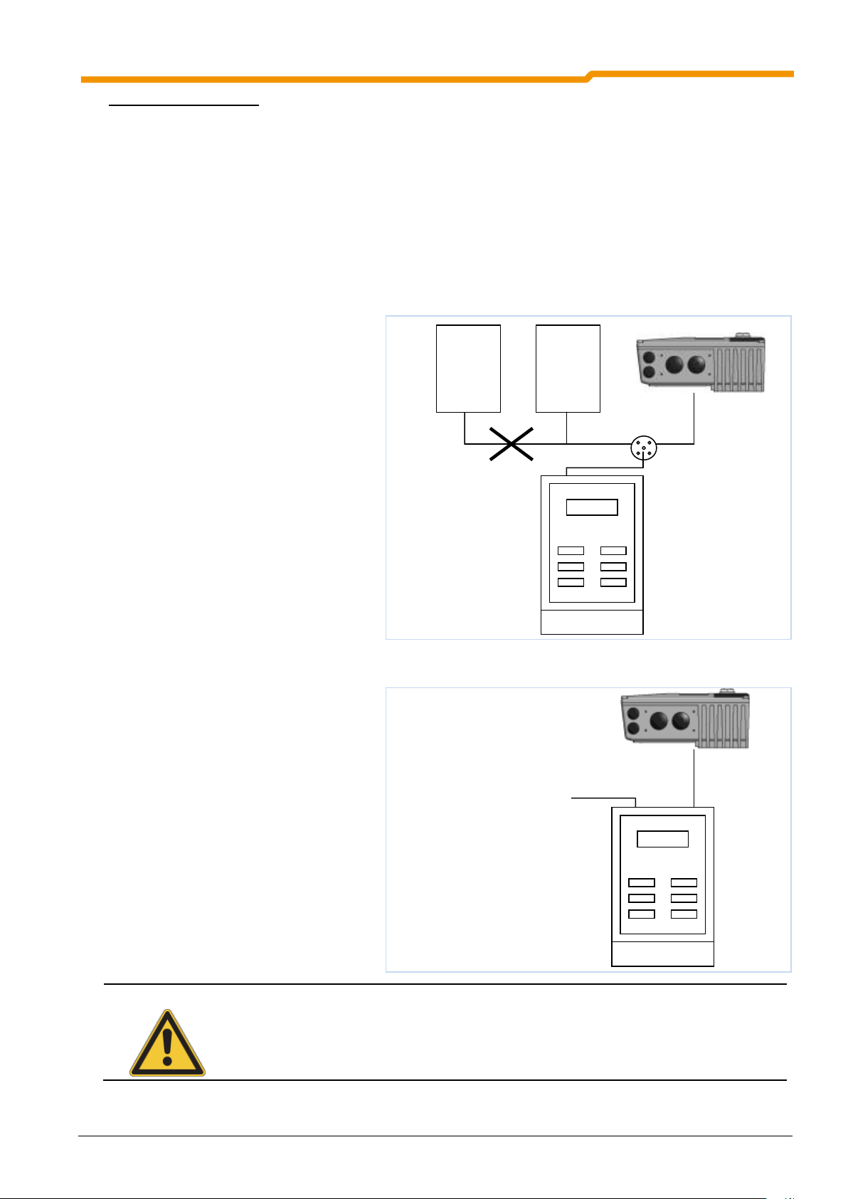
5 Commissioning
NOTE
With the SK 190E a battery-operated addressing device is sufficient.
AS-i addressing unit
AS-i -
MASTER
AS-i -
Power
AS-i addressing unit
AS-i cable
Procedure for SK 190E:
Ensure power supply of the ASi interface via the yellow ASi cable.
Disconnect the AS-i master during addressing
Set the address ≠ 0
Do not doubly assign addresses
Normal hand-held units can be used for the addressing of the frequency inverter. Typical manufacturers are
Pepperl+Fuchs (e.g.: VBP-HH1-V3.0-V1) and IFM (E.g.: AC1154).
The following lists the possibilities for the practical implementation of addressing an SK 190E with an
addressing box.
Version 1
With a normal addressing device
(equipped with an M12 plug for
connection to the AS-i bus) the AS-i can
be integrated into the AS-i network via a
suitable access point. The prerequisite for
this is that the AS-i master can be
switched off.
Version 2
With an addressing unit (equipped with
an M12 plug for connection to the AS-i
bus and an additional M12 plug for an
external power supply), the addressing
unit can be directly connected into the
AS-i cable.
BU 0180 GB-0914 Pre-series version 73
Page 74

SK 180E Manual for frequency inverters
Designation
Value
Supply via AS interface connection PWR connection (yellow cable)
24 V,
max. 25 mA
Slave profile
S-7.A
I/O-Code
7
ID Code
A
External ID Code 1 / 2
7
Address
1A – 31A and 1B - 31B
(condition as delivered: 0A)
5.4.5 Technical data for AS interface
74 Pre-series version BU 0180 GB-0914
Page 75

6 Parameterisation
Example illustration
Parameter set dependent (P) parameter selections in P100
Parameter number
Parameter text
Top: P-Box display
Bottom: Meaning
Supervisor parameters (S)
Depend on the setting in P003
Array value
Parameter value range
Factory settings of parameter
e.g. only available for size 2 is relevant
Description
6 Parameterisation
The frequency inverter, field bus and I/O -extension modules each have their own logic systems. These can
be adapted to customers' requirements by means of changeable parameters. The basic functions of the
particular modules are factory-set, so that the units have basic functionalities on delivery. Limited
adaptations of individual functions of the relevant devices can be implemented vie DIP switches. For all
further adjustments, access to the parameters of the relevant device with the aid of a ParameterBox
(SK PAR-3H, SK CSX-3H) or NORD CON software is essential. It should be noted that the hardware
configuration (DIP - switches) has priority over configuration via software (parameterisation).
NOTE: For use on the SK 1x0E the ParameterBox SK PAR-3H must have at least the software
version 4.4 R2.
The following describes the relevant parameters for the frequency inverter (Section 6.1) and the I/O
extension modules (Section 6.2). Explanation for parameters which relate to the field bus options can be
obtained from the relevant supplementary manuals.
Availability of the parameters
Due to certain configurations, the parameters are subject to certain conditions. The following tables (from
Section 6.1 onwards) list all parameters together with the particular information.
Array parameter display
Some parameters have the option of displaying settings and views in several levels (arrays). After the
parameter is selected, the array level is displayed and must then also be selected.
BU 0180 GB-0914 Pre-series version 75
Page 76

SK 180E Manual for frequency inverters
P_01
P502
P_02
OFF
OFF
Setting:
Value of master function 1
Setting:
Value of master function 2
ENTER
ENTER
ENTER
VALUE
NOTE
As there are dependencies between parameters, it is possible for invalid internal data and
operating faults to be generated briefly. Only the inactive or non-critical parameter sets should
be adjusted during operation.
Menu group No.
Master function
Operating displays (P0--):
For the selection of the physical units of the display value.
Basic parameters (P1--):
Contain the basic inverter settings, e.g. switch on and switch off procedures and,
along with the motor data, are sufficient for standard applications.
Motor data (P2--):
Settings for the motor-specific data, important for ISD current control, and
selection of characteristic curve during the setting of dynamic and static boost.
Control terminals (P4--):
Analog input and output scaling, specification of digital input and relay output
functions, as well as PI controller parameters.
Extra functions (P5--):
Functions dealing with e.g. the BUS interface, pulse frequency or fault
acknowledgement.
Information (P7--):
Display of e.g. actual operating values, old error messages, equipment status
reports or software version.
Array parameters -01
...
-xx
Some parameters in these groups can be programmed and read in several levels
(arrays). After the parameter is selected, the array level must also be selected.
ATTENTION
All current parameter settings will be overwritten, if P523= 1 is set and confirmed with "OK".
To save the actual parameter settings, these can be transferred to the ParameterBox memory.
ParameterBox SK PAR-3H
If the SimpleBox SK CSX-3H is used, the array level is shown by _ - 0 1 . With the ParameterBox SK PAR3H (picture on right) the selection options for the array level appear at the top right of the display.
SimpleBox SK CSX-3H
6.1 Frequency inverter parameterisation
Every frequency inverter is factory-set for a motor of the same power. All parameters can be adjusted
"online". There are four switchable parameter sets available during operation. As delivered, all parameters
are visible; however, some can be hidden with parameter P003.
The individual parameters are combined in various groups. The first digit of the parameter number indicates
the assignment to a menu group:
NOTE: Parameter P523 can be used to load the factory settings for all parameters at any time. This
can be helpful, e.g. during the commissioning of a frequency inverter whose parameters no
longer correspond with the factory settings.
76 Pre-series version BU 0180 GB-0914
Page 77

Parameter list - inverter functions (selection)
Parameter
Description
Factory
setting
Settings / functions (selection)
P102
Start-up time
Start-up time (acceleration ramp) is the
time corresponding to the linear
frequency rise from 0 Hz to the set
maximum frequency (P105).
[2.00]
Note: Values < 0.1 must be avoided
P103
Deceleration
time
The braking time (braking ramp) is the
time corresponding to the linear
frequency reduction from the set
maximum frequency (P105) to 0Hz.
[2.00]
Note: Values < 0.1 must be avoided
P104
Minimum
frequency
The minimum frequency is the
frequency supplied by the FI as soon as
it is enabled and no additional setpoint
is set.
[0]
P105
Maximum
frequency
Is the frequency provided by the FI after
it has been enabled and the maximum
setpoint value is available.
[50]
P200
motor list
If a 4-pole NORD motor is used, the
preset motor data can be called up.
[0]
Select appropriate motor power
P201 – P208
Motor data
If a 4-pole NORD motor is not used, the
motor data on the rating plate must be
entered here.
[xxx]
Data according to rating plate
P220
Parameter
identification
The motor data is automatically
determined by the FI with this
parameter.
[0]
01= only stator resistance
02= motor identification
P400
Setpoint input
function
Definition of the functions of the various
setpoint inputs
Input selection:
AIN1 (P400, [-01])
AIN2 (P400, [-02])
[xxx]
00= no function
01= setpoint frequency
P420
Digital input
functions
Definition of the functions of the various
digital inputs
Input selection:
DIN 1 (P420, [-01])
DIN 2 (P420, [-02])
DIN 3 (P420, [-03])
[xxx]
00= no function
01= enable right
02= enable left
04= fixed frequency 1
P428
Automatic
starting
Inverter enable with "Mains On"
[0]
0= Off (enable with flank)
1= On (enable with level)
Note: one digital input must be
programmed and set to enable.
P465
Fixed frequency /
Fixed frequency
array
Definition of fixed frequency values
Selection:
Fixed frequency 1 (P465, [-01])
Fixed frequency 2 (P465, [-02])
[xxx]
P509
Source Control
Word
Selection of the interface via which the
FI is controlled.
[0]
00= Control terminals or keyboard
01= Only control terminals
03= System bus
P523
Factory setting
Frequency inverter is restored to the
factory setting
[0]
00= No change
01= Load factory setting
6 Parameterisation
BU 0180 GB-0914 Pre-series version 77
Page 78

SK 180E Manual for frequency inverters
Parameter
Description
Settings / functions (selection)
P700
Actual operating
status
Display of current messages for the actual operating
status of the frequency inverter such as faults,
warnings or the cause of a switch-on block.
Selection:
Actual fault (P700, [-01])
Actual warning (P700, [-02])
Reason for switch-on block (P700, [-03])
Error group:
1 / 2 = Overtemperature of inverter / motor
3 / 4 = Overcurrent error
5 = Overvoltage error
16 = Motor phase monitoring
19…= Parameter identification error
P701
Last fault
Displays the last 5 frequency inverter faults.
Selection:
Last fault (P701, [ -01])
Second to last fault (P701, [-02])
See P700
P707
Software version
Displays the firmware version / Inverter revision
Selection:
Software version (P707, [-01])
Revision (P707, [-02])
P708
Digital input
status
Shows the switching status of the digital inputs.
Bit 0 = DIN 1
Bit 1 = DIN 2
…
P709
Analog input
voltage
Displays the measured analog input value.
Input selection:
AIN1 (P400, [-01])
AIN2 (P400, [-02])
P719
Actual current
Displays the actual output current.
P740
Process data
Bus In
Displays the actual control word and the setpoints.
[-01] = STW (Source P509)
[-02…-04] SW 1…3 (Source P510[-01]
[-11…-13] SW 1…3 (Source P510[-02]
P749
DIP switch status
Displays the actual DIP switch setting (S1).
Bit 0 = DIP switch 1
Bit 1 = DIP switch 2
…
Parameter list - inverter information (selection)
78 Pre-series version BU 0180 GB-0914
Page 79

6.1.1 Operating displays
Parameter
{Factory setting}
Setting value / Description / Note
Device
Supervisor
Parameter
set
P000
Operating para. disp.
(Operating parameter display)
0.01 ... 9999
In the SimpleBox (SK CSX-3H) display, the parameter value online selected in P100 is
displayed.
P001
Selection display
(Selection display)
0 ... 65
{ 0 }
0 = Actual frequency [Hz], is the actual output frequency being supplied by the FI.
1 = Speed [rpm], the actual speed calculated by the FI.
2 = Setpoint frequency [Hz], the output frequency equivalent to the actual setpoint. This
need not match the actual output frequency.
3 = Current [A], the actual output current measured by the FI.
4 = Torque current [A], the torque developing output current of the FI.
5 = Voltage [V AC], the actual alternating voltage being output by the FI.
6 = Link voltage [V DC], "link voltage" is the internal DC voltage of the FI. Amongst other
things, this depends on the level of the mains voltage.
7 = cos Phi, the currently calculated value of the power factor.
8 = Apparent power [kVA], the actual apparent power calculated by the FI.
9 = Effective power [kW], the actual effective power calculated by the FI.
10 = Torque [%], the actual torque calculated by the FI.
11 = Field [%], the actual field in the motor calculated by the FI.
12 = Operating hours [h]: time that voltage is applied to the FI network.
13 = Operating time Enable [h], "Enable operating hours" is the time for which the FI is
enabled.
14 = Analog input 1 [%], actual value AIN1 of the first I/O extension SK xU4-IOE.
15 = Analog input 2 [%], actual value AIN2 of the second I/O extension SK xU4-IOE.
16 = … 18 reserved
19 = Heat sink temperature [°C]: current temperature of the FI heat sink.
20 = Motor load [%]: average motor load, based on the known motor data (P201...P209).
21 = Brake resistor load - R [%], "Brake resistor load" average brake resistor load, based on
the known resistance data (P556...P557).
22 = Internal temperature [°C], current temperature in FI housing.
23 = Motor temperature [°C], only in combination with the analog input and appropriate
wiring (KTY84).
30 = Actual motor potentiometer setpoint [Hz], advance display of the setpoint (without the
drive unit running) can be set via the motor potentiometer function 71 / 72 (see
parameter P420).
50 = … 54 reserved
60 = R Stator Ident: stator resistance, automatic determination of motor data, P220
61 = R Rotor Ident: rotor resistance, automatic determination of motor data, P220
62 = L Leakage Stator Ident, stator leakage inductance, from automatic determination of
motor data, P220
63 = L Stator Ident: stator inductance, from automatic determination of motor data, P220
64 = Reserved
65 = Reserved
The abbreviations used are described in Section 9.12 “Abbreviations in this Manual".
BU 0180 GB-0914 Pre-series version 79
6 Parameterisation
Page 80

SK 180E Manual for frequency inverters
Parameter
{Factory setting}
Setting value / Description / Note
Device
Supervisor
Parameter
set
P002
Display factor
(Display factor)
S
0.01 ... 999.99
{ 1.00 }
The selected operating value in parameter P001 >Select of display< is multiplied with the
scaling factor in P000 and displayed in >Operating parameter display<.
It is therefore possible to display system-specific operating such as e.g. the throughput quantity
P003
Supervisor code
(Supervisor code)
0 ... 9999
{ 1 }
0 = The Supervisor parameters are not visible. Otherwise, all parameters are visible.
1 = All parameters are visible.
2 = ... 9999, (except 65) only parameters P001 and P003 are visible.
Parameter
{Factory setting}
Setting value / Description / Note
Device
Supervisor
Parameter
set
P100
Parameter set
(Parameter set)
S
0 ... 3
{ 0 }
Selection of the parameters sets to be parameterised. 4 parameter sets are available. All
parameter set-dependent parameters are identified by P.
The selection of the operating parameter set is performed via a digital input or the Bus control.
Switching can take place during operation (online).
Setting
Digital input
function [8]
Digital input
function [17]
LEDs
SimpleBox
0 =
Parameter set 1
Low
Low
1
2
1 =
Parameter set 2
High
Low
2
1
2 =
Parameter set 3
Low
High
1
2
3 =
Parameter set 4
High
High
2
1
If enabled via the keyboard (SimpleBox, PotentiometerBox or ParameterBox), the operating
parameter set will match the settings in P100.
6.1.2 Basic parameter (frequency inverter)
80 Pre-series version BU 0180 GB-0914
Page 81

6 Parameterisation
Parameter
{Factory setting}
Setting value / Description / Note
Device
Supervisor
Parameter
set
P101
Copy
(Copy parameter set
S
0 ... 4
{ 0 }
After confirmation with the OK key, a copy of the parameter set selected in P100 >Parameter
set< is written to the parameter set dependent on the value selected here
0 = Do not copy
1 = Copy actual to P1: copies the active parameter set to parameter set 1
2 = Copy actual to P2: copies the active parameter set to parameter set 2
3 = Copy actual to P3: copies the active parameter set to parameter set 3
4 = Copy actual to P4: copies the active parameter set to parameter set 4
P102
Acceleration time
(Acceleration time)
P
0.05 ... 320.00 sec
{ 2.00 }
Start-up time (acceleration ramp) is the time corresponding to the linear frequency rise from 0Hz
to the set maximum frequency (P105). If an actual setpoint of <100% is being used, the
acceleration time is reduced linearly according to the setpoint which is set.
The acceleration time can be extended by certain circumstances, e.g. FI overload, setpoint lag,
smoothing, or if the current limit is reached.
Notes on ramp gradient:
Amongst other things, the ramp gradient is governed by the inertia of the rotor.
A ramp with a gradient which is too steep may result in the "inversion" of the motor.
In general, extremely steep ramps (e.g.: 0 - 50Hz in < 0.1 s) should be avoided, as may cause
damage to the frequency inverter.
P103
Deceleration time
(Deceleration time)
P
0.05 ... 320.00 sec
{ 2.00 }
Deceleration time (braking ramp) is the time corresponding to the linear frequency reduction from
the set maximum frequency (P105) to 0Hz. If an actual setpoint <100% is being used, the
deceleration time reduces accordingly.
The braking time can be extended by certain circumstances, e.g. by the selected >Switch-off
mode< (P108) or >Ramp smoothing< (P106).
Notes on ramp gradient: see parameter (P102)
P104
Minimum frequency
(Minimum frequency)
P
0.0 ... 400.0 Hz
{ 0.0 }
The minimum frequency is the frequency supplied by the FI as soon as it is enabled and no
additional setpoint is set.
In combination with other setpoints (e.g. analog setpoint of fixed frequencies) these are added to
the set minimum frequency.
This frequency is undershot when
a) the drive is accelerated from standstill.
b) The FI is blocked. The frequency then reduces to the absolute minimum (P505)
before it is blocked.
c) The FI is reversing. The reverse in the rotation field takes place at the absolute
minimum frequency (P505).
This frequency can be continuously undershot if, during acceleration or braking, the function
"Maintain frequency" (Function Digital input = 9) is executed.
P105
Maximum frequency
(Maximum frequency)
P
0.1 ... 400.0 Hz
{ 50.0 }
The frequency supplied by the FI after being enabled and once the maximum setpoint is present,
e.g. analog setpoint corresponding to P403, a correspondingly fixed frequency or maximum via
the SimpleBox / ParameterBox.
This frequency can only be overshot by the slip compensation (P212), the function "Maintain
frequency" (function digital input = 9) or a change to another parameter set with lower maximum
frequency.
BU 0180 GB-0914 Pre-series version 81
Page 82
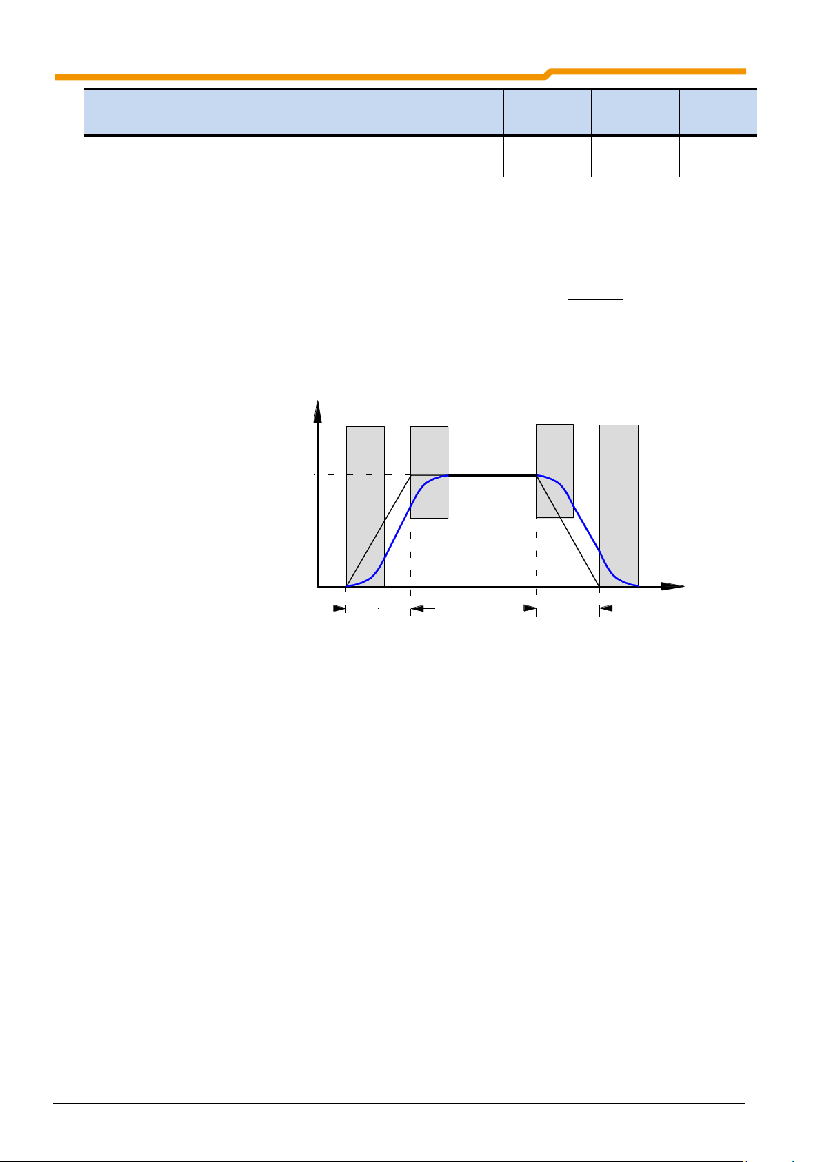
SK 180E Manual for frequency inverters
Parameter
{Factory setting}
Setting value / Description / Note
Device
Supervisor
Parameter
set
P106
Ramp smoothing
(Ramp smoothing)
S P
0 ... 100 %
{ 0 }
This parameter enables a smoothing of the acceleration and deceleration ramps. This is
necessary for applications where gentle, but dynamic speed change is important.
Ramp smoothing is carried out for every setpoint change. The value to be set is based on the set
acceleration and deceleration time, however values <10% have no effect.
The following then applies for the entire acceleration or deceleration time, including rounding:
100%
% P106
P102P102TIME ATION ACCELERtot
ttt
100%
% P106
P103P103TIME ONDECELERATI tot
ttt
P102
P103
Output
frequency
Desired
frequency
Time
each
10 – 100% of P102
each
10 – 100% of P103
82 Pre-series version BU 0180 GB-0914
Page 83

6 Parameterisation
Parameter
{Factory setting}
Setting value / Description / Note
Device
Supervisor
Parameter
set
P107
Brake reaction time
(Brake reaction time)
P
0 ... 2.50 s
{ 0.00 }
Electromagnetic brakes have a physically-dependent delayed reaction time when actuated. This
can cause a dropping of the load for lifting applications, as the brake only takes over the load
after a delay.
This reaction time can be taken into account under parameter (P107).
Within the adjustable application time, the FI supplies the set absolute minimum frequency (P505)
and so prevents movement against the brake and load drop when stopping.
See also the parameter >Release time< (P114)
NOTE: The optional module SK CU4-MBR must be used for the control of electromagnetic
brakes (especially for lifting gear). The minimum absolute frequency (P505) should
never be less than 2.0Hz.
NOTE: If a time > 0 is set in (P107) or (P114), at the moment the FI is switched on, the level
of the excitation current (field current) is checked. If no magnetising current is
present, the FI remains in magnetising mode and the motor brake is not released.
NOTE: If brake control is used, care must be taken that parameter (P107) is not set to 0
Recommendation for applications:
Lifting equipment with brake, without speed feedback Lifting equipment with brake
P114 = 0.2...0.3 sec. *
P107 = 0.2...0.3 sec. *
P201…P208 = Motor data
P505 = 2...4 Hz
for safe start-up
P112 = 401 (off)
P536 = 2.1 (off)
P537 = 150%
P539 = 2/3 (ISD monitoring)
to prevent load drops
P214 = 50...100% (precontrol)
* Setting values (P107/P114)
depend on the brake type and
motor size. For smaller powers
smaller values than those stated
may be required.
Output
frequency
P107
Brake released
P114
or
P107, when P114 = 0
ON signal
P505
OFF signal
Time
BU 0180 GB-0914 Pre-series version 83
Page 84

SK 180E Manual for frequency inverters
Parameter
{Factory setting}
Setting value / Description / Note
Device
Supervisor
Parameter
set
P108
Disconnection mode
(Disconnection mode)
S P
0 ... 13
{ 1 }
This parameter determines the manner in which the output frequency is reduced after "Blocking"
(controller enable low).
0 = Voltage block: The output signal is switched off immediately. The FI no longer supplies
an output frequency. In this case, the motor is braked only by mechanical friction.
Immediately switching the FI on again can lead to an error message.
1 = Ramp: The current output frequency is reduced in proportion to the remaining
deceleration time, from P103/P105.
2 = Ramp with delay: as with ramp, however for generational operation the brake ramp is
extended, or for static operation the output frequency is increased. Under certain
conditions, this function can prevent overload switch off or reduce brake resistance
power dissipation.
NOTE: This function must not be programmed if defined deceleration is required, e.g.
with lifting mechanisms.
3 = Immediate DC braking: The FI switches immediately to the preselected DC current
(P109). This DC current is supplied for the remaining proportion of the >DC brake time<
(P110). Depending on the relationship, actual output frequency to max. frequency
(P105), the >DC braking time< is shortened. The time taken for the motor to stop
depends on the application. This deceleration time depends of the moment of inertial of
the load and the DC current which is set (P109).
With this type of braking, no energy is fed back to the FI. Heat losses occur, mainly in the
rotor of the motor.
4 = Const. brake distance, „Constant brake distance“: The brake ramp is delayed in starting
if the equipment is not being driven at the maximum output frequency (P105). This
results in an approximately similar braking distance for different frequencies.
NOTE: This function cannot be used as a positioning function. This function should not
be combined with ramp smoothing (P106).
5 = Combined braking, „Combined braking“: Dependent on the actual link voltage, a high
frequency voltage is switched to the basic frequency (linear characteristic curves only,
P211 = 0 and P212 = 0). The deceleration time is retained where possible (P103).
additional motor warming!
6 = Quadratic ramp: The brake ramp does not follow a linear path, but rather a decreasing
quadratic one.
7 = Quad. ramp with delay, "Quadratic ramp with delay": Combination of functions 2 and 6
8 = Quad. combined braking "Quadratic combined braking": Combination of functions 5 and 6
9 = Const.acc.pwr., „Constant acceleration power“: Only applies in field weakening range!
The drive is accelerated or braked using constant electrical power.
10 = Distance calculator: Constant distance between actual frequency / speed and the set
minimum output frequency (P104).
11 = Con. acc. pwr. w. delay, "Constant acceleration power with delay": Combination of
functions 2 and 9.
12 = Const. Accln. Power Mode3: as 11 with additional brake chopper relief
13 = As for 1- ramp, however, before the brake is applied, the drive unit remains at the absolute
minimum frequency set in parameter (P505) for the time specified in parameter (P110).
84 Pre-series version BU 0180 GB-0914
Page 85

6 Parameterisation
Parameter
{Factory setting}
Setting value / Description / Note
Device
Supervisor
Parameter
set
P109
DC brake current
(DC brake current)
S P
0 ... 250 %
{ 100 }
Current setting for the functions of DC current braking (P108 = 3) and combined braking (P108 = 5).
The correct setting value depends on the mechanical load and the required deceleration time.
A higher setting brings large loads to a standstill more quickly.
The 100% setting relates to a current value as stored in the >Nominal current< parameter P203.
NOTE: The amount of DC current (0 Hz) which the FI can supply is limited. For this value,
plese refer to the table in Section 9.4.3, column: 0 Hz. In the basic setting this
limiting value is about 110%.
P110
DC braking time on
(DC braking time on)
S P
0.00 ... 60.00 sec
{ 2.00 }
The time during which the motor has the current selected in parameter >DC brake current<
applied to it during the DC braking functions (P108 = 3).
Depending on the relationship, actual output frequency to max. frequency (P105), the >Time DC
brake on< is shortened.
The time starts running with the removal of the enable and can be interrupted by fresh enabling.
P111
P factor torque limit
(P factor torque limit)
S P
25 ... 400 %
{ 100 }
Directly affects the behaviour of the drive at torque limit. The basic setting of 100% is sufficient for
most drive tasks.
If the value is too large, the drive unit will tend to oscillate when the torque limit is reached.
If the value is too small, the programmed torque limit may be undershot.
P112
Torque current limit
(Torque current limit)
S P
25 ... 400 % / 401
{ 401 }
With this parameter, a limit value for the torque-generating current can be set. This can prevent
mechanical overloading of the drive. It cannot provide any protection against mechanical
blockages (movement to stops). A slipping clutch which acts as a safety device must be provided.
The torque current limit can also be set over an infinite range of settings using an analog input.
The maximum setpoint (compare adjustment 100%, P403[-01] . .[-06]) then corresponds to the
value set in P112.
The limit value 20% of current torque cannot be undershot by a smaller analog setpoint
(P400[-01] … [-09] = 11 or 12).
401 = OFF means the switch-off of the torque current limit! This is also the basic setting for the FI.
BU 0180 GB-0914 Pre-series version 85
Page 86

SK 180E Manual for frequency inverters
Parameter
{Factory setting}
Setting value / Description / Note
Device
Supervisor
Parameter
set
P113
Jog frequency
(Jog frequency)
S P
-400.0 ... 400.0 Hz
{ 0.0 }
When using the SimpleBox or ParameterBox to control the FI, the jog frequency is the initial
value following successful enabling.
Alternatively, when control is via the control terminals, the jog frequency can be activated via one
of the digital inputs.
The setting of the jog frequency can be done directly via this parameter or, if the FI is enabled via
the keyboard, by pressing the OK key. In this case, the actual output frequency is set in
parameter P113 and is then available for the next start.
NOTE: Specified setpoints via the control terminals, e.g. jog frequency, fixed frequencies or
analog setpoints, are generally added with the correct sign. The set maximum
frequency (P105) cannot be exceeded and the minimum frequency (P104) cannot be
undershot.
P114
Brake release time
(Brake release time)
S P
0 ... 2.50 s
{ 0.00 }
Electromagnetic brakes have a delayed reaction time during ventilation, which depends on
physical factors. This can lead to the motor running while the brake is still applied, which will
cause the inverter to switch off with an overcurrent report.
This release time can be taken into account in parameter P114 (Brake control).
During the adjustable ventilation time, the FI supplies the set absolute minimum frequency (P505)
thus preventing movement against the brake.
See also the parameter >Brake reaction time< P107 (setting example).
NOTE: If the brake release time is set to "0", then P107 is the brake release and reaction
time.
P120 [-01]
...
[-04]
Options monitoring
(Options monitoring)
S
0 ... 2
{ 1 }
Monitoring of communication at system bus level (in case of fault: error message 10.9)
Array levels:
Setting value for each array:
[-01] = Extension 1 (BUS TB)
[-02] = Extension 2 (second I/O TB)
[-03] = Extension 3 (first I/O TB)
[-04] = Extension 4 (reserved)
14 = Monitoring OFF
15 = Auto, communication is only monitored if an
existing communication is interrupted. If a
module which was previously present is not
found when the network is switched on, this
does not result in an error.
Monitoring only becomes active when the
extension begins communication with the FI.
16 = Monitoring active immediately "Monitoring
active immediately“ , the FI starts monitoring the
corresponding module immediately after it is
switched on. If the module is not detected on
switch-on, the FI remains in the status "not
ready for switch-on" for 5 seconds and then
triggers an error message..
Note: If fault messages which are detected by the optional module (e.g. faults at field bus level)
are not to result in a shut-down of the frequency inverter, parameter (P513) must also be set to
the value {-0,1}.
86 Pre-series version BU 0180 GB-0914
Page 87

6.1.3 Motor data / characteristic curve parameters
Parameter
{Factory setting}
Setting value / Description / Note
Device
Supervisor
Parameter
set
P200
Motor list
(Motor list)
P
0 ... 51
{ 0 }
Adjustment of the motor data from a list for 4-pole IE1 DS standard motors.
By selecting one of the possible digits and pressing the OK key, all motor parameters
(P201…P209) are adjusted to the selected standard power. The basis for the motor data is a
4-pole IE1 DS standard motor
0 = no change "No change to data"
1 = No motor: In this setting, the FI operates without current control, slip compensation and
pre-magnetising time, and is therefore not recommended for motor applications.
Possible applications are induction furnaces or other applications with coils and
transformers. The following motor data is set here:
50.0 Hz / 1500 rpm / 15.0 A / 400 V / 0.00 kW / cos =0.90 / Star / RS 0,01 / I
EMPTY
6.5 A
2 = 0.12 kW 230 V
3 = 0.16 PS 230 V
4 = 0.18 KW 230 V
5 = 0.25 PS 230 V
6 = 0.25 kW 230 V
7 = 0.33 Hp 230 V
8 = 0.25 kW 400 V
9 = 0.33 Hp 460 V
10 = 0.37 kW 230 V
11 = 0.50 Hp 230 V
12 = 0.37 kW 400 V
13 = 0.50 Hp 460 V
14 = 0.55 kW 230 V
15 = 0.75 Hp 230 V
16 = 0.55 kW 400 V
17 = 0.75 Hp 460 V
18 = 0.75 kW 230 V
19 = 1.0 Hp 230 V
20 = 0.75 kW 400 V
21 = 1.0 Hp 460 V
22 = 1.1 kW 230 V
23 = 1.5 Hp 230 V
24 = 1.1 kW 400 V
25 = 1.5 Hp 460 V
26 = 1.5 kW 230 V
27 = 2.0 PS 230 V
28 = 1.5 kW 400 V
29 = 2.0 PS 460 V
30 = 2.2 kW 230 V
31 = 3.0 PS 230 V
32 = 2.2 kW 400 V
33 = 3.0 PS 460 V
34 = 3.0 kW 230 V
35 = 4.0 PS 230 V
36 = 3.0 kW 400 V
37 = 4.0 PS 460 V
38 = 4.0 kW 230 V
39 = 5.0 PS 230 V
40 = 4.0 kW 400 V
41 = 5.0 PS 460 V
42 = 5.5 kW 230 V
43 = 7.5 PS 230 V
44 = 5.5 kW 400 V
45 = 7.5 PS 460 V
46 = 7.5 kW 230 V
47 = 10 PS 230 V
48 = 7.5 kW 400 V
49 = 10.0 PS 460 V
50 = 11.0 kW 400 V
51 = 15.0 PS 460 V
NOTE: As P200 returns to = 0 after the input confirmation, the control of the set motor can
be implemented via parameter P205.
P201
Nominal motor frequency
(Nominal motor frequency)
S P
10.0 ... 399.9 Hz
{***}
The motor nominal frequency determines the V/f break point at which the FI supplies the
nominal voltage (P204) at the output.
P202
Nominal motor speed
(Nominal motor speed)
S P
150 ... 24000 rpm
{***}
The nominal motor speed is important for the correct calculation and control of the motor slip
and the speed display (P001 = 1).
P203
Nominal motor current
(Nominal motor current)
S P
0.1 ... 300.0 A
{***}
The nominal motor current is a decisive parameter for the current vector control.
6 Parameterisation
*** These settings are dependent on the nominal power of the FI or the selection in parameter P200.
BU 0180 GB-0914 Pre-series version 87
Page 88

SK 180E Manual for frequency inverters
Parameter
{Factory setting}
Setting value / Description / Note
Device
Supervisor
Parameter
set
P204
Nominal motor voltage
(Nominal motor voltage)
S P
100 ... 800 V
{]
The >Nominal voltage< matches the mains voltage to the motor voltage. In combination with the
nominal frequency, the voltage/frequency characteristic curve is produced.
P205
Nominal motor power
(Nominal motor power output)
P
0.00 ... 150.00 kW
{
***
}
The motor nominal power controls the motor set via P200.
P206
Motor cos phi
(Motor cos )
S P
0.50 ... 0.90
{
***
}
The motor cos is a decisive parameter for the current vector control.
P207
Motor circuit
(Motor circuit)
S P
0 ... 1
{
***
}
0 = Star
1 = Delta
The motor circuit is decisive for stator resistance measurement (P220) and therefore for current
vector control.
P208
Stator resistance
(Stator resistance)
S P
0.00 ... 300.00
{
***
}
Motor stator resistance restistance of a phase winding with a DC motor.
Has a direct influence on the current control of the FI. Too high a value will result in a possible
overcurrent, on the other hand a value which is too low will result in a motor torque which is too low.
The parameter P220 can be used for simple measurement. Parameter P208 can be used for
manual setting or as information about the result of an automatic measurement.
NOTE: For optimum functioning of the current vector control, the stator resistance must be
automatically measured by the FI.
P209
No load current
(No load current)
S P
0.1 ... 300.0 A
{
***
}
This value is always calculated automatically from the motor data if there is a change in the
parameter >cos < P206 and the parameter >Nominal current< P203.
NOTE: If the value is to be entered directly, then it must be set as the last motor data. This
is the only way to ensure that the value will not be overwritten.
P210
Static boost
(Static boost)
S P
0 ... 400 %
{ 100 }
The static boost affects the current that generates the magnetic field. This is equivalent to the
no load current of the respective motor and is therefore load-independent. The no load current
is calculated using the motor data. The factory setting of 100% is sufficient for normal
applications.
P211
Dynamic boost
(Dynamic boost)
S P
0 ... 150 %
{ 100 }
The dynamic boost affects the torque generating current and is therefore a load-dependent
parameter. The factory 100% setting is also sufficient for typical applications.
Too high a value can lead to overcurrent in the FI. Under load therefore, the output voltage will
be raised too sharply. Too low a value will lead to insufficient torque.
*** These settings are dependent on the nominal power of the FI or the selection in parameter P200.
88 Pre-series version BU 0180 GB-0914
Page 89

6 Parameterisation
Parameter
{Factory setting}
Setting value / Description / Note
Device
Supervisor
Parameter
set
P212
Slip compensation
(Slip compensation)
S P
0 ... 150 %
{ 100 }
The slip compensation increases the output frequency, dependent on load, to keep the
asynchronous motor speed approximately constant.
The factory setting of 100% is optimal when using DC asynchronous motors and correct motor
data has been set.
If several motors (different loads or outputs) are operated with one FI, the slip compensation
P212 must be set to 0%. This rules out a negative influence. This is equally valid for
synchronous motors that do not have slip due to their design.
P213
Amplification ISD control
(amplification of ISD control)
S P
25 ... 400 %
{ 100 }
This parameter influences the control dynamics of the FI current vector control (ISD control).
Higher settings make the controller faster, lower settings slower.
Dependent on application type, this parameter can be altered, e.g. to avoid unstable operation
P214
Torque precontrol
(Torque precontrol)
S P
-200 ... 200 %
{ 0 }
This function allows a value for the expected torque requirement to be set in the controller. This
function can be used in lifting applications for a better load transfer during start-up.
NOTE:Motor torques (with rotation field right) are entered with a positive sign, generator torques
are entered with a negative sign. The reverse applies for the counter clockwise rotation.
P215
Boost precontrol
(Boost precontrol)
S P
0 ... 200 %
{ 0 }
Only advisable with linear characteristic curve (P211 = 0% and P212 = 0%).
For drives that require a high starting torque, this parameter provides an option for switching in
an additional current during the start phase. The application time is limited and can be selected
at parameter >Time boost precontrol< P216.
All current and torque current limits that may have been set (P112 and P536, P537) are
deactivated during the boost lead time.
Note: With active ISD control (P211 and / or P212 ≠ 0) parameterisation of P216 ≠ 0 results
in incorrect control.
P216
Time boost precontrol
(Time boost precontrol)
S P
0.0 ... 10.0 sec
{ 0.0 }
This parameter is used for 3 functionalities
Time limit for the boost lead: Effective time for the increased starting current.
Only with linear characteristic curve (P211 = 0% and P212 = 0%).
Time limit for suppression of pulse switch-off (P537): enables start-up under heavy load.
Time limit for suppression of switch-off on error in parameter (P401), setting { 05 } „0 – 10 V
with switch-off on error 2“
BU 0180 GB-0914 Pre-series version 89
Page 90

SK 180E Manual for frequency inverters
Parameter
{Factory setting}
Setting value / Description / Note
Device
Supervisor
Parameter
set
P217
Oscillation damping
(Oscillation damping)
S P
0 ... 400 %
{ 10 }
With the oscillation damping, idling current harmonics can be damped. Parameter 217 is a
measure of the damping power.
For oscillation damping the oscillation component is filtered out of the torque current by means
of a high pass filter. This is amplified by P217, inverted and switched to the output frequency.
The limit for the value switched is also proportional to P217. The time constant for the high pass
filter depends on P213. For higher values of P213 the time constant is lower.
With a set value of 10% for P217, a maximum of ± 0.045 Hz are switched in. At 400% in P217,
this corresponds to ± 1.8 Hz
P218
Modulation depth
(Modulation depth)
S
50 ... 110 %
{ 100 }
This setting influences the maximum possible output voltage of the FI in relation to the mains
voltage. Values <100% reduce the voltage to values below that of the mains voltage if this is
required for motors. Values >100% increase the output voltage to the motor increased the
harmonics in the current, which may cause swinging in some motors.
Normally, 100% should be set.
P219
Auto. Magn.adjustm.
(Automatic magnetisation adjustment)
S
25 ... 100 % / 101
{ 100 }
With this parameter, an automatic adjustment of the magnetizing to the motor load can be
made. P219 is a limiting value, to which the field in the motor can be reduced.
As standard, the value is set to 100%, and therefore no reduction is possible. As minimum, 25%
can be set.
The reduction of the field is performed with a time constant of approx. 7.5 sec. On increase of
load the field is built up again with a time constant of approx. 300 ms. The reduction of the field
is carried out so that the magnetisation current and the torque current are approximately equal,
so that the motor is operated with “optimum efficiency”. An increase of the field above the
setpoint value is not intended.
This function is intended for applications in which the required torque only changes slowly (e.g.
pumps and fans). Its effect therefore replaces a quadratic curve, as it adapts the voltage to the
load.
NOTE: This must not be used for lifting or applications where a more rapid build-up of the
torque is required, as otherwise there would be overcurrent switch-offs or inversion
of the motor on sudden changes of load, because the missing field would have be
compensated by a disproportionate torque current.
101 = automatic, with the setting P219=101 an automatic magnetisation current controller is
activated. The ISD controller then operates with a subordinate magnetizing controller,
which improves the slippage calculation, especially at higher loads. The control times
are considerably faster compared to the Normal ISD control (P219 = 100)
90 Pre-series version BU 0180 GB-0914
Page 91

6 Parameterisation
Parameter
{Factory setting}
Setting value / Description / Note
Device
Supervisor
Parameter
set
P2xx
Control/characteristic curve parameters
NOTE: "typical"
P211
P210
P204
P201
P216
P215
Output
voltage
Output frequency
Time
Settings for the...
Current vector control (factory setting)
P201 to P209 = Motor data
P210 = 100%
P211 = 100%
P212 = 100%
P213 = 100%
P214 = 0%
P215 = no significance
P216 = no significance
Linear V/f characteristic curve
P201 to P209 = Motor data
P210 = 100% (static boost)
P211 = 0%
P212 = 0%
P213 = no significance
P214 = no significance
P215 = 0% (dynamic boost)
P216 = 0s (time dyn. boost)
P220
Para. identification
(Parameter identification)
P
0... 2
{ 0 }
Duration up to 240 s
The motor data is automatically determined by the FI with this parameter. In most cases this
leads to considerably better drive characteristics, as DC asynchronous motors are subject to
manufacturing tolerances which are not documented on the rating plate.
If unfavorable operating characteristics result, select a suitable motor in P200 or set the
parameters P201 … P208 manually.
0 = No identification
1 = Identification RS: only the stator resistance (display in P208) is determined.
2 = Motor identification: all motor parameters (P202, P203, P206, P208, P209) are
determined.
Procedure:
a) The identification should be made with the motor cold. Warming up of the motor during
operation is automatically taken into account.
b) The FI must be in an “operative condition”‘. For Bus operation, the Bus must be
operating without error. The FI must not be in a state of switch-on block.
c) The motor power may only be one power level greater or 3 power levels lower than the
nominal power of the FI.
d) The motor data should be set according to the rating plate or P200. However, at least
the nominal frequency (P201), the nominal speed (P202), the voltage (P204), the power
(P205) and the motor circuit (P207) should be known.
e) If the identification cannot be concluded successfully, the error message E019 is
generated. See also Section 6, Error messages.
f) Reliable identification can be made with motor cables up 20m in length.
NOTE: After identification of parameters, P220 is again = 0.
Care must be taken that the connection to the motor is not interrupted during the
entire measuring process.
BU 0180 GB-0914 Pre-series version 91
Page 92

SK 180E Manual for frequency inverters
Parameter
{Factory setting}
Setting value / Description / Note
Device
Supervisor
Parameter
set
P400 [-01]
...
[-07]
Fnct. setpoint inputs
(Function of setpoint inputs)
P
0 ... 36
{ [-01] = 1 }
{ [-02] = 0 }
{ [-03] = 0 }
{ [-04] = 0 }
{ [-05] = 0 }
{ [-06] = 0 }
{ [-07] = 0 }
[-01] = Analog input 1, Function of analog input 1 integrated into the FI
[-02] = Analog input 2, Function of analog input 2 integrated into the FI
[-03] = Ext. Analog input 1, AIN1 of the first I/O extension (SK xU4-IOE)
[-04] = Ext. Analog input 2, AIN2 of the first I/O extension (SK xU4-IOE)
[-05] = Ext. A.in 1 2nd IOE, AIN1 of the second I/O extension (SK xU4-IOE)
[-06] = Ext. A.in 2 2nd IOE, AIN2 of the second I/O extension (SK xU4-IOE)
[-07] = Setpoint module, in preparation ... setting values below.
For standardisation of actual values: See also (Section 9.9 ).
0 = Off, the analog input has no function. After the FI has been enabled via the control
terminals, it will supply the set minimum frequency (P104).
1 = Setpoint frequency, the given analog range (P402/P403) varies the output frequency
between the set minimum and maximum frequencies (P104/P105).
2 = Frequency addition **, the supplied frequency value is added to the setpoint.
3 = Frequency subtraction **, the supplied frequency value is subtracted from the setpoint.
4 = Minimum frequency, setting of the minimum frequency of the inverter (= 0 – 100% from P104)
5 = Maximum frequency, setting of the maximum frequency of the inverter (= 0 – 100% from P105)
6 = Actual value process controller *, activates the process controller, analog input is
connected to the actual value encoder (compensator, air can, flow volume meter, etc.).
The mode is set via the DIP switches of the I/O extension or in (P401).
7 = Setpoint process controller *, as for Function 14, however, the setpoint is specified (e.g.
by a potentiometer). The actual value must be specified using another input.
8 = Actual PI frequency *, is required to set up a control loop. The analog input (actual value)
is compared with the setpoint (e.g. fixed frequency). The output frequency is adjusted as
far as possible until the actual value equals the setpoint. (see control variables
P413...P414)
9 = Actual freq. PI limited *, "Actual frequency PI limited“, as for function 8 "Actual frequency
PI", however the output frequency cannot fall below the programmed minimum frequency
value in Parameter P104. (no change to rotation direction)
10 = Actual freq. PID monitored *, "Actual frequency PID monitored", as for function 8 Actual
frequency PI", however the FI switches the output frequency off when the minimum
frequency P104 is reached
11 = Torque current limit, "Torque current limited" depends on parameter (P112). This value
corresponds to 100% of the setpoint value. When the set limit value is reached, there is a
reduction of the output frequency at the torque current limit.
12 = Torque current limit switch-off, "Torque current limit switch-off" depends on parameter
(P112). This value corresponds to 100% of the setpoint value. When the set limit value is
reached, the device switches off with error code E12.3.
13 = Current limit, "Current limited" depends on parameter (P536). This value corresponds to
100% of the setpoint value. When the set limit value is reached, the output voltage is
reduced in order to limit the output current.
14 = Current switch-off, "Current limit switch-off", depends on parameter (P536), this value
corresponds to 100% of the setpoint value. When the set limit value is reached, the
device switches off with error code E12.4.
15 = Ramp time, "Ramp time" is normally only used in combination with a potentiometer.
Standardisation: T_Ramp time= 10s * U[V] / 10V (U=Potentiometer voltage).
6.1.4 Control terminals
92 Pre-series version BU 0180 GB-0914
Page 93

6 Parameterisation
Parameter
{Factory setting}
Setting value / Description / Note
Device
Supervisor
Parameter
set
16 = Torque precontrol, a function that enables a value for the anticipated torque requirement
to be entered in the controller (interference factor switching). This function can be used to
improve the load take-up of lifting equipment with separate load detection.
17 = Multiplication, the setpoint is multiplied with the analog value supplied. The analog value
adjusted to 100% then corresponds to a multiplication factor of 1.
18 = Curve travel calculator, via the external analog input (P400 [-03] or P400 [-04]) or via the
BUS (P546 [-01 .. -03]) the master receives the actual speed from the slave. From its own
speed, the slave speed and the guide speed, the master calculates the actual setpoint
speed, so that neither of the two drives travels faster than the guide speed in the curve.
19 = Reserved
25 = Transfer Factor Gearing, "Gearing Transfer Factor", is a multiplier to compensate for the
variable transfer of a setpoint value. E.g.: Setting of the transformation between the
master and the slave by means of a potentiometer.Reserved
30 = Motor temperature: enables measurement of the motor temperature with a
KTY-84 - temperature sensor (Details in Section 5.3)
33 = Setpoint torque proc. cntrl., “Setpoint torque process controller“, For even distribution of
the torques to coupled drive units (e.g.: synchronised roller drive). This function is also
possible with the use of ISD control.
34 = d-correction. F process - (Diameter correction, PI process controller frequency).
35 = d-correction. Torque - (Diameter correction, torque).
36 = d-correction. F+Torque- (Diameter correction, PI process controller frequency and
torque).
*) For further details of the PI and process controller, please refer to Section 9.2.
**) The limits of these values are formed by the parameters >minimum frequency auxiliary
setpoint values< (P410) and the parameter >maximum frequency auxiliary setpoint values<
(P411), whereby the limits defined by (P104) and (P105) cannot be undershot or overshot.
P401 [-01]
...
[-06]
Analog On mode
(Mode analog input)
0 ... 5
{ all 0 }
[-01] = Analog input 1, Function of analog input 1 integrated into the FI
[-02] = Analog input 2, Function of analog input 2 integrated into the FI
[-03] = Ext. Analog input 1, AIN1 of the first I/O extension (SK xU4-IOE)
[-04] = Ext. Analog input 2, AIN2 of the first I/O extension (SK xU4-IOE)
[-05] = Ext. A.in 1 2nd IOE, AIN1 of the second I/O extension (SK xU4-IOE)
[-06] = Ext. A.in 2 2nd IOE, AIN2 of the second I/O extension (SK xU4-IOE)
0 = 0 – 10 V limited: An analog setpoint smaller than the programmed adjustment 0% (P402)
does not lead to undershooting of the programmed minimum frequency (P104).
BU 0180 GB-0914 Pre-series version 93
Page 94

SK 180E Manual for frequency inverters
Parameter
{Factory setting}
Setting value / Description / Note
Device
Supervisor
Parameter
set
1 = 0 – 10 V: If a setpoint smaller than the programmed adjustment 0% (P402) is present,
this may cause a change in the direction of rotation. This allows rotation direction reversal
using a simple voltage source and potentiometer.
E.g. internal setpoint with reversal of direction of rotation: P402 = 5V, P104 = 0 Hz,
Potentiometer 0–10 V Rotation direction change at 5V in mid-range setting of the
potentiometer.
At the moment of reversal (hysteresis = P505), the drive stands still when the minimum
frequency (P104) is smaller than the absolute minimum frequency (P505). A brake that is
controlled by the FI will have entered the hysteresis range.
If the minimum frequency (P104) is greater than the absolute minimum frequency (P505),
the drive reverses when the minimum frequency is reached. In the hysteresis range
P104, the FI supplies the minimum frequency (P104), the brake controlled by the FI is not
applied.
2 = 0 – 10V monitored: If the minimum
adjusted setpoint (P402) is undershot by
10% of the difference value from (P403)
and (P402), the FI output switches off
As soon as the setpoint is greater than
[P402 - (10% * (P403 - P402))] it
delivers an output signal again.
f / Hz
P104
(fmin)
P105
(fmax)
P403 = 10.0V
P402 = 2.0V
= 8.0V
U/V
OFF = 2.0V - 10% * 8.0V = 1.2V
E.g. setpoint 4-20 mA:: P402: Adjustment 0% = 1V; P403: Adjustment 100% = 5 V; 10% corresponds to -0.4 V; i.e. 1...5 V (4...20 mA) normal operating zone, 0.6...1 V =
minimum frequency setpoint, below 0.6 V (2.4 mA) output switches off.
NOTE:
The SK xU4-IOE provides the frequency inverter with a value standardised to 0…100%.
In addition, the frequency inverter also receives a bit, which confirms that the analog
input signal is within the defined limits.
Example: Setpoint: 4 … 20 mA
0…4 mA = 0% (0000
hex
)
20 mA = 100% (4000
hex
)
≥ 2 mA = Bit "Setpoint value valid"
If the "0-10 V monitored" mode is selected, the bit "Setpoint value valid" is evaluated and
if the setpoint value is undershot by a value of 2mA, the inverter output is switched off.
NOTE:
Settings of parameters (P402) and (P403) are treated in an additive manner, i.e. they
can be used for additional adjustment of the limiting values.
3 = - 10V – 10 V: If a setpoint smaller than the programmed adjustment 0% (P402) is
present, this may cause a change in the direction of rotation. This allows reversal of the
direction of rotation using a simple voltage source and potentiometer.
E.g. internal setpoint with reversal of direction of rotation: P402 = 5 V, P104 = 0 Hz,
Potentiometer 0–10 V Rotation direction change at 5V in mid-range setting of the
potentiometer.
94 Pre-series version BU 0180 GB-0914
Page 95

6 Parameterisation
Parameter
{Factory setting}
Setting value / Description / Note
Device
Supervisor
Parameter
set
At the moment of reversal (hysteresis = P505), the drive stands still when the minimum
frequency (P104) is smaller than the absolute minimum frequency (P505). A brake which
is controlled by the FI has not been applied in the hysteresis range.
If the minimum frequency (P104) is greater than the absolute minimum frequency (P505),
the drive reverses when the minimum frequency is reached. In the hysteresis range
P104, the FI supplies the minimum frequency (P104), the brake controlled by the FI is not
applied.
NOTE: The function -10V – 10V is a description of the method of function and not a
reference to a bipolar signal (see example above).
4 = 0 – 10V with error 1, “0 – 10 V with switch-off on error 1“: If the 0% adjustment value in
(P402) is undershot, the error message 12.8 "Analog In Min. undershot" is activated.
Overshooting of the 100% adjustment value in (P403) activates the error message 12.9
"Analog In Max. overshot".
Even if the analog value is within the limits defined in (P402) and (P403), the setpoint
value is limited to 0 - 100%.
The monitoring function only becomes active if there is an enable signal and the analog
value has reached the valid range (≥(P402) or ≤(P403)) for the first time (E.g. Build-up of
pressure after switching on a pump).
5 = 0 – 10V with error 2, “0 – 10 V with switch-off on error 2“:
See setting 4 ("0 – 10 V with error switch off 1“), however:
In this setting the monitoring function only becomes active if an enable signal is present
and the time during which the error monitoring is suppressed has elapsed. This
suppression time is set in parameter (P216).
BU 0180 GB-0914 Pre-series version 95
Page 96

SK 180E Manual for frequency inverters
Parameter
{Factory setting}
Setting value / Description / Note
Device
Supervisor
Parameter
set
P402 [-01]
...
[-06]
Adjustment: 0%
(Analog input adjustment: 0%)
S
-50.00 ... 50.00 V
{ all 0.00 }
[-01] = Analog input 1, Function of analog input 1 integrated into the FI
[-02] = Analog input 2, Function of analog input 2 integrated into the FI
[-03] = Ext. Analog input 1, AIN1 of the first I/O extension (SK xU4-IOE)
[-04] = Ext. Analog input 2, AIN2 of the first I/O extension (SK xU4-IOE)
[-05] = Ext. A.in 1 2nd IOE, AIN1 of the second I/O extension (SK xU4-IOE)
[-06] = Ext. A.in 2 2nd IOE, AIN2 of the second I/O extension (SK xU4-IOE)
This parameter sets the voltage which should correspond with the minimum value of the selected
function for the analog input 1 or 2. In the factory setting (setpoint) this value is equivalent to the
setpoint set via P104 >Minimum frequency<.
Note
SK 1x0E
For the adjustment of the integrated analog inputs of the SK1x0E to the type of analog signals, the
following values must be set:
0 – 10 V → 0.00 V
2 – 10 V → 2.00 V
0 – 20 mA → 0.00 V (switch in internal resistance via DIP switch S1 (Section.: 5.2.2.2)
4 – 20 mA → 1.00 V (switch in internal resistance via DIP switch S1 (Section.: 5.2.2.2)
SK xU4-IOE
Standardisation to typical signals, such as 0(2)-10V or 0(4)-20mA is carried out via the DIP switch
on the I/O-extension module. In this case, additional adjustment of parameters (P402) and (P403)
must not be carried out.
P403 [- 01]
...
[- 06]
Adjustment: 100%
(Analog input adjustment: 100%)
S
-50.00 ... 50.00 V
{ all 0.00 }
[-01] = Analog input 1, Function of analog input 1 integrated into the FI
[-02] = Analog input 2, Function of analog input 2 integrated into the FI
[-03] = Ext. Analog input 1, AIN1 of the first I/O extension (SK xU4-IOE)
[-04] = Ext. Analog input 2, AIN2 of the first I/O extension (SK xU4-IOE)
[-05] = Ext. A.in 1 2nd IOE, AIN1 of the second I/O extension (SK xU4-IOE)
[-06] = Ext. A.in 2 2nd IOE, AIN2 of the second I/O extension (SK xU4-IOE)
This parameter sets the voltage which should correspond with the maximum value of the selected
function for the analog input 1 or 2. In the factory setting (setpoint) this value is corresponds with
the setpoint set via P105 >Maximum frequency<.
Note
SK 1x0E
For the adjustment of the integrated analog inputs of the SK1x0E to the type of analog signals, the
following values must be set:
0 – 10 V → 10.00 V
2 – 10 V → 10.00 V
0 – 20 mA → 5.00 V (switch in internal resistance via DIP switch S1 (Section.: 5.2.2.2)
4 – 20 mA → 5.00 V (switch in internal resistance via DIP switch S1 (Section.: 5.2.2.2)
SK xU4-IOE
Standardisation to typical signals, such as 0(2)-10V or 0(4)-20mA is carried out via the DIP switch
on the I/O-extension module. In this case, additional adjustment of parameters (P402) and (P403)
must not be carried out.
96 Pre-series version BU 0180 GB-0914
Page 97

6 Parameterisation
Parameter
{Factory setting}
Setting value / Description / Note
Device
Supervisor
Parameter
set
P400 ... P403
Output
frequency
P104
z.B. 0,0 V 2,5 V 5,0 V 10,0 V
P105
positive
P402
P403
Setpoint
voltage
Output
frequency
P104
z.B. 0,0 V 2,5 V 5,0 V 10,0 V
P105
positive
negative
P402
P403
Setpoint
voltage
P404 [-01]
[-02]
Analog input filter
(analog input filter)
S
10 ... 400 ms
{ all 100 }
Adjustable digital low-pass filter for the analog signal. Interference peaks are hidden, the reaction
time is extended.
[-01] = Analog input 1
[-02] = Analog input 2
P410
Min.freq. aux. setpt.
(Minimum frequency of auxiliary setpoints)
P
-400.0 ... 400.0 Hz
{ 0.0 }
The minimum frequency that can act on the setpoint via the auxiliary setpoints.
Auxiliary setpoints are all frequencies that are additionally delivered for further functions in the FI:
Frequency addition Frequency subtraction
Auxiliary setpoints via BUS PI process controller
PI controller Multiplication
P411
Max.freq. aux. setpt.
(Maximum frequency of auxiliary setpoints
P
-400.0 ... 400.0 Hz
{ 50.0 }
The minimum frequency that can act on the setpoint via the auxiliary setpoints.
Auxiliary setpoints are all frequencies that are additionally delivered for further functions in the FI:
Frequency addition Frequency subtraction
Auxiliary setpoints via BUS PI process controller
PI controller Multiplication
BU 0180 GB-0914 Pre-series version 97
Page 98

SK 180E Manual for frequency inverters
Parameter
{Factory setting}
Setting value / Description / Note
Device
Supervisor
Parameter
set
P412
Setpoint process controller
(Setpoint value for process controller)
S P
-10.0 ... 10.0 V
{ 5.0 }
Fixed specification of a setpoint for the process controller that will only occasionally be altered.
Only with P400 = 6 or 7 (PID process controller). Further details can be found in Section 9.2 .
P413
P-component PI-controller
(P-component of PI-controller)
S P
0.0 ... 400.0 %
{ 10.0 }
This parameter is only effective when the function PI controller actual frequency is selected.
The P-component of the PI controller determines the frequency jump if there is a control deviation
based on the control difference.
E.g.: At a setting of P413 = 10% and a rule difference of 50%, 5% is added to the actual setpoint.
P414
I-component PI-controller
(I-component of PI-controller)
S P
0.0 ... 3,000.0 %/s
{ 10.0 }
This parameter is only effective when the function PI controller actual frequency is selected.
The I-component of the PI controller determines the frequency change, dependent on time.
Note: In contrast to other NORD series, parameter P414 is smaller by a factor of 100
(Reason: better setting ability with small I-components).
P415
Process controller limit
(Control limit of process controller)
S P
0 ... 400.0 %
{ 10.0 }
This parameter is only effective when the function PI process controller is selected. This
determines the control limit (%) after the PI controller.
For further details, see Section 9.2.
P416
Ramp time PI setpoint.
(Ramp time PI setpoint value)
S P
0.00 ... 99.99 sec
{ 2.00 }
This parameter is only effective when the function PI process controller is selected.
Ramp for PI setpoint
P417 [-01]
[-02]
Offset analog output
(Offset analog output)
S P
-10.0 ... 10.0 V
{ all 0.0 }
[-01] = First IOE, AOUT of the first I/O extension (SK xU4-IOE)
[-02] = Second IOE, AOUT of the second I/O extension (SK xU4-IOE)
... only with
SK CU4-IOE or
SK TU4-IOE
In the analog output function an offset can be entered to simplify the processing of the analog
signal in other equipment.
If the analog output has been programmed with a digital function, then the difference between the
switch-on point and the switch-off point can be set in this parameter (hysteresis).
P418 [-01]
[-02]
Analog output function
(Analog output function)
S P
0 ... 33
{ all 0 }
[-01] = First IOE, AOUT of the first I/O extension (SK xU4-IOE)
[-02] = Second IOE, AOUT of the second I/O extension (SK xU4-IOE)
98 Pre-series version BU 0180 GB-0914
Page 99

Parameter
{Factory setting}
Setting value / Description / Note
Device
Supervisor
Parameter
set
... only with
SK CU4-IOE or
SK TU4-IOE
Analog functions (max. load: 5mA analog):
An analog voltage (0 ... +10 Volt) can be taken from the control terminals (max. 5mA). Various
functions are available, whereby:
0 Volt analog voltage always corresponds to 0% of the selected value.
10 V always corresponds to the motor nominal values (unless otherwise stated) multiplied by the
P419 standardisation factor, e.g.:
100%
P419 value nominal Motor
10Volt
For standardisation of actual values: See also (Section 9.9 ).
0 = No function, no output signal at the terminals.
1 = Actual frequency *, the analog voltage is proportional to the FI output frequency.
(100%=(P201))
2 = Actual speed *, this is the synchronous speed calculated by the FI based on the existing
setpoint. Load-dependent speed fluctuations are not taken into account.
3 = Current *, the effective value of the output current supplied by the FI. (100%=(P203))
4 = Torque current *, displays the motor load torque calculated by the FI. (100% = (P112))
5 = Voltage *, the output voltage supplied by the FI. (100%=(P204))
6 = Link voltage, "Link circuit voltage", is the DC voltage in the FI. This is not based on the
motor rated data. 10V Volt, standardised at 100%, is equivalent to 450V DC (230V
mains) or 850 Volt DC (480V mains)!
7 = Value from P542, the analog output can be set using parameter P542 independently of
the actual operating status of the FI. For example, with Bus switching (parameter
command) this function can supply an analog value from the FI, which is triggered by the
control unit.
8 = Apparent power *, the actual apparent power of the motor as calculated by the FI.
(100%=(P203)*(P204) or = (P203)*(P204)*√3)
9 = Effective power *, the actual effective power calculated by the FI.
(100%=(P203)*(P204)*(P206) bzw = (P203)*(P204)*(P206)*√3)
10 = Torque [%]: the actual torque calculated by the FI (100%=Nominal motor torque).
11 = Field [%] *, the actual field in the motor calculated by the FI.
12 = Actual frequency ±*, the analog voltage is proportional to the output frequency of the FI,
whereby the zero point is shifted to 5V. For rotation to the right, values between 5V and
10V are output, and for rotation to the left values between 5V and 0V.
13 = Actual speed ± *, is the synchronic rotation speed calculated by the FI, based on the
current setpoint, where the null point has been shifted to 5V. For rotation to the right,
values from 5V to 10V are output and for rotation to the left, values from 5V to 0V.
The measured speed is output via this function if servo mode is used.
14 = Torque [%] ± *, is the actual torque calculated by the FI, whereby the zero point is shifted
to 5 V. For drive torques, values between 5V and 10V are output, and for generator
torque, values between 5V and 0V.
29 = Reserved
30 = Set freq befor ramp, "Setpoint frequency before frequency ramp", displays the frequency
produced by any upstream controllers (ISD, PID, etc.). This is then the setpoint frequency
for the power stage after it has been adjusted by the start-up or braking ramp (P102,
P103).
31 = Output via BUS PZD, the analog output is controlled via a bus system. The process data
is directly transferred (P546, P547, P548).
33 = Setpoint freq. Motor pot, "Setpoint frequency of motor potentiometer"
*) Values based on the motor data (P201…), or which are calculated from this.
6 Parameterisation
BU 0180 GB-0914 Pre-series version 99
Page 100

SK 180E Manual for frequency inverters
Parameter
{Factory setting}
Setting value / Description / Note
Device
Supervisor
Parameter
set
P419 [-01]
[-02]
Analog output scaling
(Standardisation of analog output)
S P
-500 ... 500 %
{ all 100 }
[-01] = First IOE, AOUT of the first I/O extension (SK xU4-IOE)
[-02] = Second IOE, AOUT of the second I/O extension (SK xU4-IOE)
... only with
SK CU4-IOE or
SK TU4-IOE
Using this parameter an adjustment can be made to the analog output for the selected operating
zone. The maximum analog output (10 V) corresponds to the standardisation value of the
appropriate selection.
If therefore, at a constant working point, this parameter is raised from 100% to 200%, the analog
output voltage is halved. 10 Volt output signal then corresponds to twice the nominal value.
For negative values the logic is reversed. An actual value of 0% will then produce 10 V at the
output and -100% will produce 0 V.
P420 [-01]
...
[-05]
Digital inputs
(Digital inputs)
0 ... 77
{ [-01] = 1 }
{ [-02] = 2 }
{ [-03] = 4 }
{ [-04] = 0 }
{ [-05] = 0 }
Up to 3 freely programmable digital inputs are available in the SK 1x0E. In addition, the analog
inputs can also be used as digital inputs, however, their electrical characteristics are not
compatible with the SPS standard.
[-01] = Digital input 1 (DIN1), Enable right as factory setting,
control terminal 21
[-02] = Digital input 2 (DIN2), Enable left as factory setting,
control terminal 22
[-03] = Digital input 3 (DIN3), fixed frequency 1 (P465 [-01]) as factory setting,
control terminal 23
[-04] = Analog input 1 (AIN1/DIN4), no function with factory setting,
control terminal 14
[-05] = Analog input 2 (AIN2/DIN5), no function with factory setting,
control terminal 16
Various functions can be programmed. These can be seen in the following table.
The additional digital inputs of the I/O- extensions (SK xU4-IOE) are administered via the
parameter "Bus I/O In Bit (4…7)“ - (P480 [-05] … [-08]) for the first I/O extension, and via the
parameter "Bus I/O In Bit (0…3)" - (P480 [-01] … [-04]) for the second I/O extension.
100 Pre-series version BU 0180 GB-0914
 Loading...