

Page 1

GB
BU 0135
Motor Starter Manual
SK 105E…175E
Page 2

SK 105E…175E Motor Starter Manual Safety information
NORD Motor Starters
(Starters, Sort Starters, Reverse Starters)
Safety and operating instructions
for motor starters
1. General
During operation, motor starters may, depending on their protection
class, have live, bare, moving or rotating parts or hot surfaces.
Unauthorised removal of covers, improper use, incorrect inst allation
or operation causes a risk of serious personal injury or material
damage.
Further information can be found in this documentation.
All transportation, installation, initialisation and maintenance work
must be carried out by qualified personnel (compliant with IEC
364, CENELEC HD 384, DIN VDE 0100, IEC 664 or DIN VDE 0110,
and national accident prevention regulations).
For the purposes of these basic safety instructions, qualified personnel are persons who are familiar with the ass embly, installation,
commissioning and operation of this product and who have the relevant qualifications for their work.
2. Proper use in Europe
Motor starters are components intended for ins tallation in electrical
systems or machines.
When installed in machines, the drive power convert er must not be
commissioned (i.e. commencement of the proper use) until it has
been ensured that the machine m eets the provisions of the EC Directive 2006/42/EEC (Machinery Directive); EN 60204 must also be
complied with.
Commissioning (i.e. implementation of t he proper use) is only permitted if the EMC directive (2004/108/EEC) is complied with.
CE-labelled m otor starters meet the requirements of the Low Voltage Directive 2006/95/EEC. The harmonized standards stated in the
Declaration of Conformity are used for the drive power converters.
Technical data and information for connection conditions can be
found on the rating plate and in the documentation, and must be
complied with.
The motor starters may only be used for safety functions which are
described and explicitly approved.
3. Transport, storage
Information regarding transport, storage and correct handling must
be complied with.
4. Installation
The installation and cooling of the equipment must be implemented
according to the regulations in the corresponding documentation.
(as per: Low Voltage Directive 2006/95/EEC)
The motor starter must be protected against impermissible
loads. Especially during transport and handling, components must not be deformed and/or insulation distances
must not be changed. Touching of electronic components
and contacts must be avoided.
Motor starters have electrostatically sensit ive components,
which can be easily damaged by incorrect handling. Electrical components must not be mechanically damaged or destroyed (this may cause a health hazard!).
5. Electrical connections
When working on live drive components, the applicable national accident prevention regulations must be complied with
(e.g. BGV A3, formerly VBG 4).
The electrical installation must be im plement ed according t o
the applicable regulations (e.g. cable cross-section, fuses,
earth lead connections). Further instruct i ons can be found in
the documentation.
Information about EMC-compliant installation – such as
shielding, earthing, location of filters and installation of cables can be found in the drive power converter docum entation. These instructions must be complied with even with CE
marked motor starters. Compliance with the limiti ng values
specified in the EMC regulations is the responsibility of t he
manufacturer of the system or machine.
6. Operation
Systems in which motor starters are installed must be
equipped, where necessary, with addi tional monitoring and
protective equipment as per the applicable safety requirements, e.g. legislation concerning technical equipment, accident prevention regulations, etc.
The parameterisation and configuration of the m otor starter
must be selected so that no hazards can occur.
All covers must be kept closed during operation.
7. Maintenance and repairs
After the motor starter is disconnect ed from the power supply, live equipment components and power connections
should not be touched immediately, because of possible
charged capacitors. Observe the relevant information signs
located on the drive power converter.
Further information can be found in this documentation.
These safety instructions must be kept in a safe place!
2 BU 0135 GB-2713
Page 3

SK 105E…175E Motor Starter Manual Concerning this document
Documentation
Designation: BU 0135 GB
Part No.: 607 1302
Device series: SK 105E, SK 115E, SK 125E, SK 135E, SK 145E, SK 155E, SK 165E, SK 175E
Device types: SK 1x5E-301-340-A, SK 1x5E-751-340-A, 0.25 - 7.5kW, 3~ 200-500V
Version list
Designation of
previous issues
BU 0135 GB, July 2013
Part No. 607 1302 / 2713
Software
Version
V 1.0 R0 First version based on BU 0200 DE / 2011
Publisher
Getriebebau NORD GmbH & Co. KG
Rudolf-Diesel-Str. 1 • D-22941 Bargteheide • http://www.nord.com/
Tel.: +49 (0) 45 32 / 289-0 • Fax +49 (0) 45 32 / 289-2555
Intended use of the motor starter:
Compliance with the operating instructions is essential for fault-free operation and the
acceptance of any warranty claims. These operating instructions must be read before
working with the device!
These operating instructions contain important information about servicing. They must
therefore be kept close to the device.
SK 1x5E motor starters are devices for industrial and commercial plants for operating
three-phase asynchronous motors with squirrel-cage rotors.
SK 1x5E motor star ters are devices f or fixed installati on on motors or in the vicinit y of the
motors to be operate d. All details regarding technical data and permissible conditions
at the installation site must be complied with.
Commissioning (commencement of the intended use) is not permitted until it has be en e ns ured
that the machine com plies with the EMC Directive 2004/108/EEC and that th e conformity of
the end product meets the Machiner y Direct iv e 2006/42/EEC (observe EN 60204).
Comments
Getriebebau NORD GmbH & Co. KG, 2013
BU 0135 GB-2713 3
Page 4

SK 105E…175E Motor Starter Manual
1 GENERAL INFORMATION ...................................................................................................... 6
1.1 Overview .............................................................................................................. 7
1.2 Delivery ................................................................................................................ 7
1.3 Scope of supply ................................................................................................... 8
1.4 Safety and installation information ...................................................................... 9
1.5 Certifications ...................................................................................................... 10
1.6 Nomenclature / type codes ................................................................................ 12
1.7 Version with protection class IP55 / IP66 .......................................................... 15
2 ASSEMBLY AND INSTALLATION ....................................................................................... 16
2.1 Installation and assembly .................................................................................. 16
2.2 Dimensions of the motor starter ........................................................................ 20
2.3 Wiring guidelines ............................................................................................... 23
2.4 Electrical Connection ......................................................................................... 24
2.5 Electrical connection of the power unit .............................................................. 25
2.6 Electrical connection of SK 1x5E control unit .................................................... 28
2.7 Plug connectors ................................................................................................. 32
2.8 ATEX Zone 22 for SK 1x5E (in preparation) ..................................................... 35
2.9 Outdoor installation ............................................................................................ 40
1.5.1 European EMC Directive ........................................................................................ 10
1.5.2 UL and cUL approval(in preparation) ...................................................................... 10
1.5.3 C-Tick labelling ....................................................................................................... 11
1.5.4 RoHS compliance ................................................................................................... 11
1.6.1 Type code for basic unit .......................................................................................... 13
1.6.2 Type codes / Adapter unit - Technology Unit .......................................................... 13
1.6.3 Type codes / Optional modules .............................................................................. 13
2.1.1 Mounting the hous ing bo x ....................................................................................... 17
2.1.2 Adapters for different motors .................................................................................. 18
2.1.3 Installation of the motor starter ............................................................................... 19
2.1.4 Option locations in the device ................................................................................. 20
2.2.1 Power rating / Motor size ........................................................................................ 20
2.2.2 SK 1x5E mounted on motor .................................................................................... 21
2.2.3 SK 1x5E for wall-mounting...................................................................................... 22
2.5.1 Mains connections (L1, L2, L3, PE) ........................................................................ 26
2.5.2 Motor cable (U, V, W, PE)....................................................................................... 26
2.5.3 Electro-mechanical brake ....................................................................................... 27
2.6.1 SK 1x5E control terminal versions .......................................................................... 29
2.6.2 Details of the SK 1x5E control connections ............................................................ 30
2.6.3 Control connections for SK 1x5E communication ................................................... 31
2.7.1 Plug connectors for power connections .................................................................. 32
2.7.2 Plug connectors for control connection ................................................................... 33
2.8.1 Modified SK 1x5E for compliance with Category 3D ............................................... 36
2.8.2 Options for ATEX Zone 22 3D ................................................................................ 36
2.8.3 Commissioning information..................................................................................... 38
2.8.4 EC Declaration of Conformity (in preparation) ........................................................ 39
3 DISPLAY AND CONTROL .................................................................................................... 41
3.1 Diagnostic LEDs on the motor starter ............................................................... 42
3.2 Overview of external control devices ................................................................. 43
4 COMMISSIONING .................................................................................................................. 44
4.1 Factory settings ................................................................................................. 44
4.2 Commissioning the motor starter....................................................................... 44
4.2.1 Connection.............................................................................................................. 44
4.2.2 Configuration .......................................................................................................... 45
4.3 AS Interface ....................................................................................................... 49
4.3.1 The bus system ...................................................................................................... 49
4 BU 0135 GB-2713
Page 5

Table of Contents
4.3.2 Features .................................................................................................................. 50
4.3.3 Bus structure and technology .................................................................................. 50
4.3.4 Commissioning of the AS Interface ......................................................................... 52
4.3.5 Technical data for AS interface ............................................................................... 55
4.3.6 Functions of the ASI I/O bits ................................................................................... 55
4.4 PROFIBUS ................................................... Fehler! Textmarke nicht definiert.
4.4.1 Features .................................................................................................................. 56
4.4.2 Connection .............................................................................................................. 56
4.4.3 Addressing .............................................................................................................. 57
4.4.4 Displays .................................................................................................................. 58
4.4.5 Process data ........................................................................................................... 59
5 PARAMETERISATION ........................................................................................................... 60
5.1 Parameter ........................................................................................................... 61
5.1.1 Operating displays .................................................................................................. 62
5.1.2 Basic parameters .................................................................................................... 63
5.1.3 Motor and characteristic curve parameters ............................................................. 66
5.1.4 Control terminals ..................................................................................................... 67
5.1.5 Additional parameters ............................................................................................. 69
5.1.6 Information .............................................................................................................. 72
6 OPERATING STATUS MESSAGES ...................................................................................... 77
6.1 SimpleBox display .............................................................................................. 77
6.2 Table of possible error messages ...................................................................... 78
6.3 Table of possible warning messages ................................................................. 79
6.4 Table of possible reasons for the operating status "switch-on disabled" ........... 79
7 TECHNICAL DATA ................................................................................................................. 80
7.1 General data forSK 1x5E motor starter series ................................................... 80
7.2 Motor starter electrical data ................................................................................ 81
7.3 Electromagnetic compatibility ............................................................................. 82
7.4 EMC limit value classes ..................................................................................... 83
7.5 Operation with FI circuit breakers ....................................................................... 83
8 ADDITIONAL INFORMATION ................................................................................................ 84
8.1 Maintenance and servicing information .............................................................. 84
8.1.1 Maintenance Instructions ........................................................................................ 84
8.1.2 Repair information ................................................................................................... 84
8.2 Abbreviations in this manual .............................................................................. 85
9 KEYWORD INDEX .................................................................................................................. 86
BU 0135 GB-2713 5
Page 6

SK 105E…175E Motor Starter Manual
1 General information
The SK 1x5E series is based on the tried and tested NORD platform. These devices feature a compact
design with optimum characteristics.
Due to dual phase control, not onl y a pure motor start, but also a soft start is possible. T he phase control
process was selected s o that the res ulting harm onic torques are k ept as low as possible. A c omprehensiv e
spectrum of monitoring functions rounds off the range.
This series of devices can be adapted to individual requirements by means of extension modules.
Due to the numerous setting options, these inverters are capable of operating all three-phase motors.
The power range is from 0.25kW to 7.5kW. The device is equipped with an integrated mains filter.
This manual is based on the device sof tware V1.0 R0 (see P707) of the motor s tarter. If the motor star ter
uses a different software version, this may cause differences. If necessary, the latest manual should be
downloaded from the Internet (www.nord.com
For the various versions of the device series SK 105E…SK 175E there are differences in functions, the
integrated AS interface or the integrated PROFIBUS interface.
Typically, this series of devices is installed directly on a three-phase asynchronous motor. Alternatively,
optional accessories are available for m ounting the devices close to the motor, e.g. on the wall or on a
machine frame.
In the simplest config uration, ev en without a PC or contr ol box, all of the mos t important par ameter s can be
set using up to four potent iometers and the four DIP switches . LEDs are pr ovided for the diagnostics of the
operating status. The use of a control module is therefore not absolutely necessary.
In order to gain access to all parameters, the internal RS232 PC interface (RJ12) can be used, or an
optional SimpleBox or Param eterBox may be used. I n this case, t he parameter settings which are changed
by the user are saved in the flash memory of the device.
A permanent connection via the RS 232 interface is not intended for normal operation.
).
6 Pre-series version BU 0135 GB-2713
Page 7

1.1 Overview
x x x
x
This manual describes al l of the possib le f unctions and equ ipm ent. T he equipm ent and f unctions are limited
according to the t ype of device (SK 105 E…175E). T ype SK 175E d evices have t he maxim um configuration
level.
Basic features of the SK 1x5E:
• 2 digital inputs
• 2 digital outputs
• Temperature sensor input (TF+/TF-)
• Control and connection of an electromechanical brake
2
• Motor overload protection (I
• Mains and motor phase failure monitoring
• Flux monitoring (monitoring of minimum current)
• Automatic phase sequence detection
• Can be installed directly on, or near to the motor
• Permissible ambient temperature -25°C to 50°C (please refer to the technical data)
• Integrated EMC line filter for limit curve category C1
• 4x DIP switches and up to four potentiometers for configuration
• LEDs for diagnostics
• RS232 interface via RJ12 plug
Additional features:
Differences between the in dividual versions (SK 10 5E / … SK 175E) are summ arised in the following table
and will be described in this manual.
Additional features
Feature 105E 115E 125E 135E 145E- 155E- 165E- 175E-
Soft start function
Reversing function
Two additional digital inputs
AS interface (4I / 4O)
PROFIBUS-DP (4I / 4O)1
SK 145E … SK 175E devic es ar e avail abl e as ( -ASI) versions with an integra ted AS i nterf ac e and as ( -PBR)
versions with integrated PROFIBUS DP. The version with integrated PROFIBUS DP is only available on
request.
t triggering characteristic according to EN 60947)
x x x x
x x x x
ASI ASI ASI ASI
PBR PBR PBR PBR
1 General
1.2 Delivery
Check the equipment immediately after delivery/unpacking for transport damage such as deformation or
loose parts.
If there is any damage, contact the carrier immediately and carry out a thorough assessment.
Important! This also applies even if the packaging is undamaged.
1
Only available on request and as an alternative to the ASI interface.
BU 0135 GB-2713 Pre-series version 7
Page 8

SK 105E…175E Motor Starter Manual
1.3 Scope of supply
Standard version: IP55 (optionally IP66)
Operating instructions as PDF file on CD-ROM
including NORD CON (PC parameterising software)
Available accessories: Matching RJ12 to SUB-D9 adapter cable to connection to a PC
(Selection) RS485-RS232 conversion for connecting control boxes
SK CSX-3H, SimpleBox, 4-digit 7-segment LED display
SK PAR-3H, ParameterBox, plain text LCD display
Expansion module:
internal SK CU4-24V-123-B, internal 24V mains unit 1~ 230V
SK CU4-24V-140-B, internal 24V mains unit 1~ 400V
SK CU4-REL, internal setpoint converter with 2 relays
SK TIE4-SWT, direction selector switch module
<
2
2
2
2
2
2
2
External SK TU4-PBR, external PROFIBUS® module
SK TU4-CAO, external CANopen® module
SK TU4-DEV, external DeviceNet™ module
SK TU4-ECT, external EtherCAT® module
SK TU4-PNT, external PROFInet® module
SK TU4-POL, external POWERLINK® module
SK TU4-EIP, external Ethernet/IP™ module
SK TU4-24V-123-B, external 24V mains unit 1~ 230V
SK TU4-24V-140-B, external 24V mains unit 1~ 400V
SK TI4-TU-BUS or NET or MSW, connection unit TU4
SK TIE4-WMK-TU, wall-mounting kit TU4
SK TU4 MSW, external maintenance switch
NOTE: Details for the use o f t he relev ant b u s sy ste ms c an be found in the applicable su pple men ta ry bu s manual .
> www.nord.com
2
External bus modules can be used to control the motor starter via their additional digital inputs and outputs.
Parameterisation via the field bus module s is not possible!
8 Pre-series version BU 0135 GB-2713
Page 9

1.4 Safety and installation information
t be maintained.
ages for up to 1
minute after being switched off at the mains. Starter terminals, motor cables and motor
Touching open or free terminals, cables and equipment components can lead to severe injury
with the electrical supply
ufacturer.
Unauthorised modifications and the use of spare parts and additional equipment which has
not been purchased from or recommended by the manufacturer of the device may cause fire,
This product is intended for use in an industrial environment and is subject to sales
cause high frequency interference, in which case the user may be required to take
SK 1x5E motor starters are equipment for use in industrial high voltage systems and are operated at
voltages that could lead to severe injuries or death if they are touched.
• Installation and other work may only be carried out by qualified electr icians and with the
device disconnected. The operating instructions must always be available to these
persons and must be strictly observed.
• Local regulations for the installation of electrical equipment and accident prevention
must be complied with.
• For safe isolation from the mains, all p oles of the sup ply cable to the m otor starter m ust
be disconnected.
• Even during motor standst ill (e.g. cause d by an electronic bl ock, block ed drive or output
terminal short circuit), t he li ne conn ection ter m inals, motor term inals an d brak ing res istor
terminals may still conduct hazardous voltages. A motor standstill is not identical to
electrical isolation from the mains.
• Warning, under certain s ettings the m otor s tarter can star t automatic ally after the mains
are switched on.
• The motor starter is onl y intended for permanent connection and m ay not be operated
without effective earthing connections that comply with local regulations for large
leakage currents (> 3.5m A). VDE 0160 stipulates the installation of a second earthing
conductor or an earthing conductor cross-section of at least 10 mm
• SK 1x5E motor starters are maintenanc e free in norm al operation. T he cooling surf aces
must be regularly cleaned with compressed air if the ambient air is dusty.
2
.
1 General
CAUTION
The heat sink and all other metal components can heat up to temperatures above 70°C.
When mounting, sufficient distance from neighbouring components mus
When working on the components, allow sufficient cooling time beforehand
Protection against accidental contact may need to be provided.
ATTENTION
DANGER TO LIFE!
Under certain circumstances, the motor starter can continue to carry volt
terminals may carry voltage!
or death!
Work may only be carried out by qualified specialist electricians and
to the equipment disconnected!
CAUTION
Children and the general public must be kept away from the equipment!
The equipment may only be used for the purpose intended by the man
electric shock and injury.
Keep these operating instructions in an accessible location and give them to all operators!
WARNING
restrictions according to IEC EN 60947-4-2. In a domestic environment, this product can
appropriate measures.
BU 0135 GB-2713 Pre-series version 9
An appropriate measure would be the inclusion of a recommended mains filter.
Page 10

SK 105E…175E Motor Starter Manual
1.5 Certifications
1.5.1 European EMC Directive
If the SK 1x5E is installed a c c ording to t he r ec om mendations in this m anual,
it meets all EMC d irective requirements, as per the EMC product st andard
for semiconductor m otor control devices EN 60947-4. (see als o Sectio n 7.3,
Electromagnetic Compatibility [EMC].)
1.5.2 UL and cUL approval (in preparation)
At present the approvals are in the process of preparation.
All SK 1x5E motor starters include motor overload protection. Further technical details can be found in
Section 7.2.
NOTE
"Integral solid state short circuit protection does not provide branch circuit protection. Branch
circuit protection must be provided in accordance with the National Electric Code and any
additional local codes."
NOTE
cUL Approval - File No. E171342
“Suitable For Use On A Circuit Capable Of Delivering Not More Than 100000 rms
Symmetrical Amperes, 500 Volt s maximum and when protected by RK5 class or faster
fuses as indicated in chapter 7.2.”
“Suitable For Use On A Circuit Capable Of Delivering Not More Than 10000 rms Symmetrical Amperes, 500 Volts
maximum and when protected by Circuit Breaker (inverse time trip type) in accordance with UL 489”, current and
voltage ratings according to instruction manual.
„The torque value for the field wiring terminals for mains circuit terminals, motor terminals, break terminals and breaking
resistor terminals must be 11 … 15 lb-in (1.2 … 1.5Nm). The torque value for the field wiring terminals for control circuit
terminals must be 4.4 … 5.3 lb-in (0.5 … 0.6Nm).”
“The device has to be mounted according to the manufacturer instructions.”
"Use 80°C Copper Conductors Only"
(only refers to connection cables (mains and motor cables but not control cables)
"These products are intended for use in a pollution degree 2 environment"
10 Pre-series version BU 0135 GB-2713
Page 11

1.5.3 C-Tick labelling
1 General
NORD SK 1x5E series motor starters fulfill all the relevant regulations in
Australia and New Zealand.
1.5.4 RoHS compliance
SK 1x5E series motor starters are designed to be RoHS compliant
according to Directi ve 2002 / 95/ EEC
N 23134
BU 0135 GB-2713 Pre-series version 11
Page 12

SK 105E…175E Motor Starter Manual
1.6 Nomenclatur e / type codes
Unique type codes have been defined for the individual modules and devices. These provide individual
details of the device type and its electrical data, protection class, fixing version and special versions.
A differentiation is made according to the following groups:
Group Example of type code
Basic unit SK 175E-751-340-A (-C)
Connection unit Technology Unit (optional terminal box module) SK TI4-TU-MSW (-C-WMK-TU)
Optional modules SK TU4-MSW (-C)
Extension modules SK TIE4-M12-INI
SK 1x5E
motor starter
Optional terminal
box module
Optional module
SK TU4-xxx (-…)
The type designation r es ult ing from this type code c an be o bta ine d f r om the name plate which is attached to
or printed on the relevant module.
12 Pre-series version BU 0135 GB-2713
Page 13

1.6.1 Type code for basic unit
SK 175E-751-340-B (-C)
IP protection class: Standard
= IP55, C =
“coated”
Radio interference filter: B = Class C1
Mains voltage: x40 = 200 - 500V
Number of mains phases: 3xx = 3-
phase
Digits before decimal point for power: 0 = 0.xx, 1 = 0x.x0, 2 = 0xx.0
Device nominal power: 301 = 3.0kW, 751 = 7.5kW
Device series: SK 105E, SK 115E, SK
125E,
SK 135E,
SK 145E, SK 155E, SK 165E, SK 175E
(...) Options, only implemented if required
.
SK TI4-TU-MSW (-C-WMK-TU)
Wall mounting kit: -1 = Size 1
+ 2
IP protection class: Standard = IP55, C = “coated” IP66
Suitable device types: NET = optional net module (e.g. TU4-24V-… )
MSW = maintenance switch
(SK TU4
-MSW
BUS = optional bus module (e.g. CANopen: TU4-CAO)
Group:
TU = Technology unit
Device series: SK TI4 = Adapter unit SK TI4
(...) Options, only implemented if required .
SK TU4-24V-123-B (-C)
IP protection class: Standard = IP55, C = “coated” IP66
Radio interference filter: B = Class C1
Mains connection: 123 = 1~ 230V*, 140 = 1~ 400V*
Option type: 24V = 24V power supply, FUSE
Option series: TU4 = external Technology Unit,
CU4 = = internal customer unit
*) The voltage depends on the motor starter used; please also refer to the technical data.
(...) Options, only implemented if required.
1 General
1.6.2 Type codes / Adapter unit - Technology Unit
1.6.3 Type codes / Optional modules
For optional modules
BU 0135 GB-2713 Pre-series version 13
Page 14

SK 105E…175E Motor Starter Manual
Optional external
Technology Unit, SK TU4-…
Optional internal
Customer Unit, SK CU4-…
14 Pre-series version BU 0135 GB-2713
Page 15

" and are modified
that the cable and the cable gland are carefully
from the device (if necessary use loops). This is the only way to ensure permanent
1.7 Version with protection class IP55 / IP66
The SK 1x5E motor starters and additio nal modules are availa ble in protection class es IP55 (standard) or
IP66 (optional).
Protection class IP66 must always be stated when ordering!
There are no restrictions or diff erences t o the scope of functions in either prot ection c lass. In or der to dif fer-
entiate the protection c lasses, m odules with prot ection c lass IP66 are g iven an ex tra “-C” (coated à coated
PCBs) in their type designation.
e.g. SK 175E-751-340-A-C
IP55 version:
The IP55 version of the SK 1x5E is t he standard version. Both vers ions (motor-mounted, m ounted on the
motor or wall-mounted on a wall brack et) are available. In additio n, all adapter units, tec hnology units and
customer units are available for this version.
IP66 version:
In contrast to the I P55 vers ion th e IP66 version is a m odified option. F or this version, bot h var iants (m otor-
integrated, close to motor) are also available. The modules available for the IP66 version (adapter units,
technology units and cus tomer units) have the same func tionalities as the corr esponding modules for the
IP55 version.
NOTE
1 General
Special measures:
Impregnated PCBs,
Powder coating RAL 9006 (white aluminium) for housing
Low pressure test
NOTE
The modules for the IP66 design are identified by an additional "-C
according to the following special measures listed below.
For all versions, care must be taken
matched. Wherever possible, the cables should be inserted so that water is deflected away
compliance with the required protection class.
BU 0135 GB-2713 Pre-series version 15
Page 16

SK 105E…175E Motor Starter Manual
2 Assembly and installation
2.1 Assembly
The motor starters are availa ble in various sizes depending on th eir output. They only differ with regar d to
their possibilities for adaption to the matching motors. The external dimensions of both sizes are
identical. Size 1 is matched to motor size 80-100. Size 2 is matched to motor size 132.
Motor-mounted version Wall-mounted version
16 Pre-series version BU 0135 GB-2713
Page 17

2 Assembly and installation
1x5E must be carried out by NORD as special measures
have to be implemented. IP66 components retrofitted on site cannot ensure that this protection
2.1.1 Mounting the housing box
On delivery of a complete drive unit (gear unit + motor + fr equency inverter) SK 1x5E motor star ters are
always fully installed and tested.
NOTE
Mounting of an IP66-compliant SK
class is guaranteed.
When delivered separately, the motor starter includes the following components:
• Motor starters
• Screws and contact washers for mounting the motor terminal box.
• Pre-fabricated cable for motor and PTC connections
Procedures:
1. If necessary, remove the original terminal box from the NORD motor, so that only the base of the
terminal box and the terminal strip remain.
2. Set the bridges for the correc t motor circuit and connect the pre-fabric ated cables for motor and PTC
connections to the respective connection points on the motor.
3. Mount the cast housing on the terminal box base of the NO RD m otor us ing the exis ting scre ws and s eal
as well as the enclos ed toothed / contact w ashers. Position the cas t housing with the d ome facing the
A-side of the motor (looking towards the A bearing cover). Check the adaptability for different motor
manufacturers.
If necessary, the plas tic cover (1) for the electronics m ust be carefully removed in order to m ake the
screw fastenings to the base of the terminal box.
4. Connect the motor cables U, V, W to the power terminal block and t he PT C cable TF+, TF- to the control
terminal block 38, 39.
BU 0135 GB-2713 Pre-series version 17
Page 18

SK 105E…175E Motor Starter Manual
Adapter plate
Seal
Motor Size 71
Motor starter SK 1x5E BGI
Example
2.1.2 Adapters for different motors
In some cases, the term inal box attachments are diff erent for different sizes of m otor. Therefore it may be
necessary to use an adapter to mount a motor starter.
In order to guarantee t he max imum protec tion class I P55 / I P66 of the e ntire un it, the pr otec tion cl ass of the
motor starter must also correspond to this value.
NORD motor
sizes
Size 63 – 71
Size 80 – 112
Size 132 not possible Direct mounting
Overview of adapter kits
Name Add-on SK 1x5E Part No.
Adapter kit size 63-71 to KK80-112
(Adapter kit I)
SK TI4-3 adapter kit_80-112
(Adapter kit II)
Add-on
SK 1x5E Size 1
with adapter kit I
Direct mounting
Adapter plate, terminal box frame seal and screws
Adapter plate, terminal box frame seal and screws
Add-on
SK 1x5E Size 2
not possible
with adapter kit II
275119050
275274321
NOTE
18 Pre-series version BU 0135 GB-2713
The adaptability of motors from other manufacturers must be checked individually!
Information for the conversion of controlled drive units to the SK 1x5E can be found in BU0320.
Page 19

2 Assembly and installation
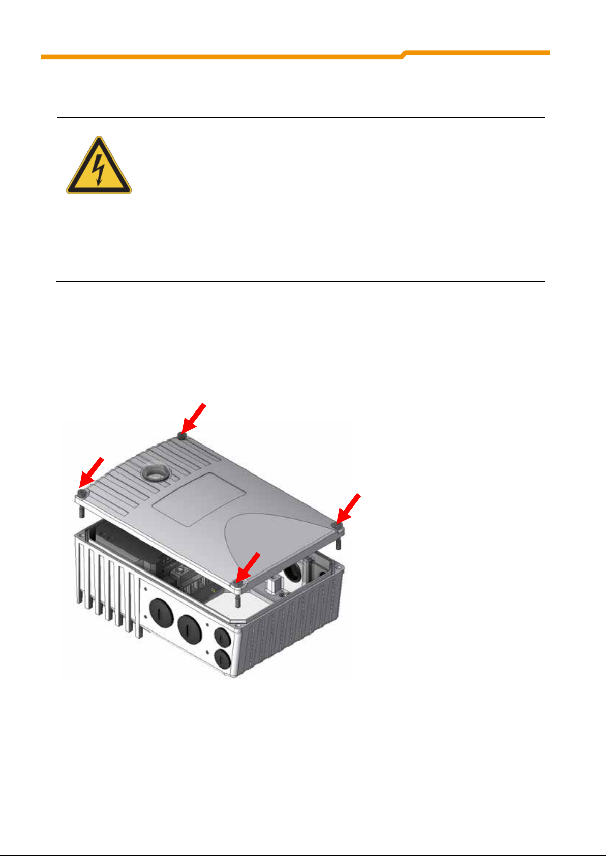
2.1.3 Installation of the motor starter
The housing cover must f irst be rem oved in or der to m ake the elect rical co nnections t o the SK 1x5E. T o do
this, unscrew the 4 fastening screws, so that the housing cover can be removed upwards.
After the electrical connections of the supply cables have been made, the housing cover can be replaced.
To achieve the maxim um protection c lass IP 55/IP6 6, care m us t be tak en that all t he fas tening sc re ws of the
housing cover are tightened diagonally, step-by-step and with the torques stated in the table below.
For the cable gland of the connecting cable , appropriate scr ewed connections f or cable cross-s ection must
be used.
Motor starter size Screw size Tightening torque
Size I M5 x 25 3.5Nm ± 20%
Size II M5 x 25 3.5Nm ± 20%
BU 0135 GB-2713 Pre-series version 19
Page 20

SK 105E…175E Motor Starter Manual
2.1.4 Option locations in the device
The drawing above shows the various mounting locations for the optional modules. Option location 1 is used
for the mounting of an internal bus module or internal mains unit. External bus modules, 24 V power
supplies can be implemented at option locations 3L or 3R. Option locations 4 and 5 are used for the
installation of M12 sockets or plug connectors or for cable glands. Of course, only one option can be
mounted at a single option location.
Option
location
1 Internal Mounting location for customer units SK CU4-…
3* on side Mounting location for
3 A/B* on side Cable gland M25 Not available if location
4 *,
5 *
* R and L (right and left side)
Position Meaning Size
Sizes 1 - 2
• External technology units SK TU4-…
• HARTING plug connectors
on side Cable gland M16 Not available if
Comments
3 is occupied or
SK TU4-… is fitted.
SK TU4-… is fitted.
2.2 Dimensions of the motor starter
2.2.1 Power rating / Motor size
Mains / Power category SK 1x5E
Size
3~ 200-240V 3~ 380-500V
Size I
Size II
20 Pre-series version BU 0135 GB-2713
0.12 ... 1.5kW 0.25 ... 3.0kW
2.2 ... 4.0kW 4.0 ... 7.5kW
Page 21

2 Assembly and installation
2.2.2 SK 1x5E mounted on motor
Size Housing dimensions SK 1x5E / Motor Weight of
FI
Motor
∅ g
g 1 n o p
SK 1x5E
without motor
Approx. [kg]
Size I
Size II
Size 71 * 145 177.5
Size 80 165 171.5 236
Size 90 S / L 183 176.5 251 / 276
Size 100 201 185.5 306
Size 80 ** 165 193.5
Size 90 S / L **
Size 100 ** 201 209.5 306
Size 112 ** 228 219.5 326
Size 132 S / M 266 216.5 373 / 411
183 198.5 251 / 276
All dimensions in [mm]
*) including additional adapter and seal (18mm) [275119050]
**) including additional adapter and seal (20mm) [275274321]
221
221
214
236
154 2.0
154 2.0
BU 0135 GB-2713 Pre-series version 21
Page 22

SK 105E…175E Motor Starter Manual
∅
2.2.3 SK 1x5E for wall-mounting
The SK 1x5E can be installed in the vicinity of the motor by means of an optional wall mounting kit.
Wall mounting
SK TIE4-WMK-1
total weight
Approx. [kg]
Device type
Size
Housing dimensions
g2 n p p2 d e
Size I à SK TIE4-WMK-1
Part No. 275 274 000
Size II à SK TIE4-WMK-2
Part No. 275 274 001
All dimensions in [mm]
113 221 154 205 64 180 5.5 2.6
115,5 221 154 235 64 180 5.5 2.6
All possible installation orientations are permissible for wall mounting.
22 Pre-series version BU 0135 GB-2713
Page 23

2 Assembly and installation
The control cables, mains cables and motor cables must be laid separately. In no
The test for high voltage insulations must not be used on cables which are connected to the
simultaneously connected to
the motor starter and the PC, as potential shifts may cause damage, especially to the PC.
2.3 Wiring guidelines
The motor starters have be en developed for use in an industr ial environm ent. In this environm ent, high le vels of electromagnetic interference can inf luence the motor starter. In genera l, correct installation ensures
safe and problem-f ree operation. To meet the limiting values of the EMC directives, the following i nstructions should be complied with.
(1) Ens ure that a ll equipm ent in th e control c abinet or field is s ecurel y earthed us ing shor t earthing c ables
which have large cross-sections a nd are connected to a comm on earthing point or earthing rail. It is
especially important th at all control dev ices connected to the motor star ter (e.g. an automat ion device)
are connected to the same earthing point as the motor starter itself, using a short cable with large
cross-section. Flat conductor s (e.g. metal clam ps) are preferable, as they have a lower impedance at
high frequencies.
(2) The bonding cable of the motor controlled by the motor starter should be connected directly to the
earthing terminal of the as sociated motor star ter. The presence of a c entral earthing bar in the contr ol
cabinet and the grouping together of all bonding conductors to this bar normally ensures safe
operation. (See also Section 7.3 / 7.4(EMC))
(3) W here possible, shielded cables should be used for control circuits. The shielding at the cable end
should be carefully sealed and it must be ensured that the wires are not laid over longer distances
without shielding.
(4) The control cables should be installed as far as possible from power cables, using separate cable
ducts, etc. Where cables cross, an angle of 90° should be ensured as far as possible.
(5) Ens ure that the contactors and brake chok es in the cabinet are interference protected , either by RC
circuits in the case of AC contactors, or by “free-wheeling” diodes for DC contactors, whereby the
interference protectors must be positioned on the contactor coils. Varistors for over-voltage
limitation are also effective.
In addition, an EMC-compliant cabling must be ensured. (See also Section 7.3 / 7.4 (EMC)).
The safety regulations must be complied with under all circumstances
when installing the motor starter!
ATTENTION
NOTE
circumstances should they be laid in the same protective pipes/installation ducts.
motor starter.
With the use of a ParameterBox SK PAR-3H this must never be
(See also Manual BU0040)
BU 0135 GB-2713 Pre-series version 23
Page 24
SK 105E…175E Motor Starter Manual
installed and commissioned by qualified personnel
In particular, the general and regional installation and safety regulations for work on high voltage
must the regulations concerning correct use of tools
Dangerous voltages can be present at the mains input and the motor connection terminals even
d screwdrivers on these terminal
Ensure that the input voltage source is not live before setting up or changing connections to the
2.4 Electrical Connection
WARNING
The housing cover must be removed from the SK 1x5E in order to make the electrical connections. Proceed
as follows:
1. Switch off the mains supply and if necessary check and observe the waiting period.
2. Loosen the 4 Allen screws (4mm).
3. Carefully lift the housing cover vertically from off the housing box.
4. The electrical connections and the option slots are now freely accessible.
THE DEVICES MUST BE EARTHED.
Safe operation of the devices requires that is
in compliance with the instructions provided in this Manual.
systems (e.g. VDE) must be complied with as
and the use of personal protection equipment.
when the motor starter is not in operation. Always use insulate
fields.
unit.
Ensure that the motor starter and motor are specified for the correct supply voltage.
5. Replace the cover
24 Pre-series version BU 0135 GB-2713
6. Evenly tighten the Allen screws in a cross-wise direction.
Page 25

2 Assembly and installation
2.5 Electrical con nect ion of the power unit
All connection terminals are located in the housing
box of the motor starter.
One terminal level is provided for the power
connections and one for the control connections.
The earthing connections (device earthing) are
located on the base in the cast housing.
Before and while the device is connected, the
following must be observed:
1. Ens ure that the m ains s uppl y provides the corr ect
voltage and is suitable for the current required
(see Section 7 Technical Data).
2. Ensure that suitable circuit breakers with the
specified nominal current range are inserted
between the voltage source and the inverter.
3. Connect the mains voltage directly to the
terminals L
4. T o connect the motor, three f lexible wires U-V-W
should be used when mounting the motor.
5. For wall-mounting a 4-conductor shielded motor
cable (recommended) to th e terminals U-V-W and
earth should be used.
NOTE: if certain wiring sleeves are used, the maximum connection cross-section can be reduced.
Screwdriver: Use a 0.6 x 3.5 mm slot-head screwdriver to connect the power unit.
NOTE: Only use copper cables with temperature class 80°C or equivalent for connection. Higher
temperature classes are permissible.
ATTENTION: This device produces high frequency int erference, whi ch may make additio nal suppression
and PE.
1-L2-L3
measures necessary in domestic environments. (Details in Section. 7.3 / 7.4 (EMC))
BU 0135 GB-2713 Pre-series version 25
Page 26

SK 105E…175E Motor Starter Manual
Main
2.5.1 Mains connections (L1, L2, L3, PE)
No special safety meas ures are required on the m ains input side of the m otor starter. It is advisable t o use
normal mains fuses (see technical data) and a main switch or circuit breaker.
400V devices are designed for three phase mains voltage 200...500V (L1/L2/L3).
For the exact specification, please refer to the technical data in Section 7.
Isolation from or c onnection to the mains must al ways be carried out for all the pol es and synchronously
(L1/L2/L3).
Connection to earth is made via screw terminals in the cast housing of the device.
Connection cross-section:
0.5...10mm
For looping of the mains voltage, up to a
cable cross-section of 2 x 4.0mm
wire end sleeves must be used.
Tightening torque:
1.2 ... 1.5Nm
2
rigid/ flexible cable AWG 20-6
2
double
PE
Main
PE
Main
2.5.2 Motor cable (U, V, W, PE)
Connection cross-section:
0.5 ... 10mm
AWG 20-6
Tightening torque:
1.2 ... 1.5Nm
2
rigid/ flexible cable
PE
Main
PE
26 Pre-series version BU 0135 GB-2713
Page 27

2 Assembly and installation
For the connection of a mechanical brake to the terminals of the motor starter, parameters
107 / P114 (brake application time / release time ) must be adjusted. In order to prevent
Brake connection terminal 79/80
2.5.3 Electro-mechanical brake
Connection of an electr omagnetic br ake is pos sible for all SK 1x5E devices . To control the brak e, an outp ut
voltage is generated to ter minals 79 / 80 (MB+ / MB-) by the motor starter to terminals 79 / 80 (MB+ / MB-)
(also refer to Sections 2.6.1 to 2.6.2). This depends on the supply voltage. The assignment is as follows:
Mains voltage / Alternating current (AC) Brake coil voltage (DC)
230 V ~ 105 V =
400 V ~ 180 V =
460 V ~ / 480 V ~ 205 V =
The allocation of the cor rect brak e or brak e coil volta ge m ust be taken into ac count in the design with reference to the mains voltage of the motor starter.
NOTE
P
damage to the brake control, a value ≠ 0 must be set in parameter (P107).
The following settings for (P107/P114) are recommended for NORD brakes:
BRE5, BRE10, BRE40 : 0.02s,
BRE20, BRE60, BRE100, BRE150: 0.03s,
BRE250: 0.04s,
Connection terminals: Screw terminals, 0.6 x 3.5 mm slot-head screwdriver
Connection cross-section: 0.2 ... 2.5mm
2
, AWG 24-14, rigid or flexible, without wire end sleeves
BU 0135 GB-2713 Pre-series version 27
Page 28

SK 105E…175E Motor Starter Manual
2.6 Electrical connection of SK 1x5E control unit
The control connections are located on the inside of the motor starter housing. The connections to the
terminal bar differ according to the version (SK 105E…175E).
Connection terminals: Spring-loaded terminal, 2.0 mm slot-head screwdriver
Connection cross-section: 0.2 ... 1.5mm
Control cable: Lay and shield separately from the mains/motor cables
Control voltages,
external: 18…30V, min. 25…100mA
the equipment and additional options. For the supply of the motor starter and
the connected options.
2
, AWG 24-16, rigid or flexible, without wire end sleeves
3
, the current load increases further according to
3
Maximum consumption by the basic device, without connected options and digital output loads (approx. 50mA for
SK 105E…135E and SK 145E…175E with optional AS interface, 100mA for SK145E…175E with optional
PROFIBUS)
28 Pre-series version BU 0135 GB-2713
Page 29

40 3 40
1 9 1
2.6.1 SK 1x5E control terminal versions
LABELLING, FUNCTION
2 Assembly and installation
SSF: Soft start function
REV: Reversing function
ASI: Integrated AS interface
PBR: Integrated PROFIBUS DP
24V: 24V power supply
DIN: Digital input
DOUT: Digital input
MB+/-: Electromagnetic brake control
(105V, 180V, 205V)
TF+/-: PTC connection of the motor
GND: Reference potential for digital signals
CONNECTIONS AND FUNCTIONS FOR SK 1X5E VERSIONS DEPENDING ON CONFIGURATION LEVEL
Terminal X4 (only SK 145E…175E):
SK 145E SK 155E SK 165E SK 175E Starter type SK 145E SK 155E SK 165E SK 175E
SSF
ASI
REV
ASI
SSF + REV
ASI
Labelling
SSF
PBR
REV
PBR
SSF + REV
PBR
Pin
GND, reference potential for digital signals
DIN4, digital input 4
(BUS-DIN2)
DIN3, digital input 3
(BUS-DIN1)
24V output max. 200mA
ASI-, AS interface
ASI+, AS interface
40
C2
C1
43
85
84
40
1
C2
2
C1
3
43
4
83
5
82
6
GND, reference potential for digital signals
DIN4, digital input 4
(BUS-DIN2)
DIN3, digital input 3
(BUS-DIN1)
24V output max. 200mA
PBR-A, PROFIBUS DP
PBR-B, PROFIBUS DP
Terminal X5:
SK 105E SK 115E SK 125E SK 135E Starter type SK 145E SK 155E SK 165E SK 175E
SSF REV SSF + REV
Labelling
Pin
SSF
ASI / PBR
REV
ASI / PBR
SSF + REV
ASI / PBR
24V, external 24V supply
24V, external 24V supply
GND, reference potential for digital signals
GND
24V, external 24V supply
DIN1 / digital input 1
DIN2, not used in
standard*
DIN2,
digital input 2
GND
DOUT1, digital output 1
DOUT2, digital output 2
GND
TF-, motor thermistor (PTC) connection
TF+, motor thermistor (PTC) connection
44
44
40
44
21
22
40
3
40
39
38
10
11
12
13
14
44
1
44
2
24V, external 24V supply
24V, external 24V supply
GND, reference potential for digital signals
40
4
44
5
21
6
22
7
40
8
DIN2, not used in
24V, external 24V supply
DIN1 / digital input 1
standard*
GND
DIN2,
digital input 2
GND
DOUT1, digital output 1
3
40
DOUT2, digital output 2
GND
39
38
TF-, motor thermistor (PTC) connection
TF+, motor thermistor (PTC) connection
*) In the state as delivered, this input is not used
BU 0135 GB-2713 Pre-series version 29
Page 30

SK 105E…175E Motor Starter Manual
2.6.2 Details of the SK 1x5E control connections
Control voltage 24V exter nal! Terminal 44. If the motor star ter is not equipped with an optiona l mains unit it
must be supplied with an external 24V voltage.
For devices with which the AS interface is used, the supply voltage can be taken from the AS interface cable
if the appropriate jumpers are set ("only yellow cable"). Otherwise the device can also have a separate
supply ("black and yellow cable"). In this case, the jumpers must not be set.
Terminal/
Name
SK 105E…SK175E
44 VI 24V 24V supply
40 GND / 0V Reference potential
21 DIN1 Digita l input 1
22 DIN2 Digita l input 2
1 DOUT1 Output 1
3 DOUT2 Output 1
38 TF+ PTC resistor input
39 TF- PTC resistor input
79 MB+ Brake control
80 MB- Brake control
Function
{Factory setting}
Input
for digital signals
{ON right}
{ON left}
{Error}
{Starter running}
Data Description /
wiring suggestion
24VDC ±25%
50mA (Starter without
accessories) ... 400mA
according to load on the
inputs and outputs or
equipment with options
Digital input as per
EN 61131-2, Type 1
Low: 0-5V (~ 9.5kΩ)
High: 15-30V
(~ 2.5-3.5kΩ)
Input capacitance: 10nF
Scanning time: 1ms
Reaction time: ≥ 4ms
Digital output
18-30V, each to VI 24V
max. 200mA
Devices with AS-I
(SK 145E or higher):
Total current 165 mA
max. 100k Ωload
-
Voltage:
Mains brake
230V 105V=
400V~ 180V=
460/480V~ 205V=
Current: max. 0.5A
Connection of the supply voltage
for the control unit and supply to
outputs DOUT1+2 as well as any
connected initiators
For control of the device from an
external control unit or switch.
For evaluation in a control system.
For monitoring the motor
temperature by PTC.
The motor starter generates an
output voltage on Terminals
MB+/MB- for control of an
electromagnetic brake. This
depends on the supply voltage to
the SK 1x5E.
It is essential to take the correct
brake coil voltage into account in
the selection.
Parameter
-
-
P420 [01]
P420 [02]
P434 [01]
P434 [02]
-
P107,
P114,
30 Pre-series version BU 0135 GB-2713
Page 31

RS485_A
RS485_B
GND
TXD
RXD
+5V
+24V
n.c.
n.c.
6: +24V
Additionally for SK 145E ... SK 175E
43 24V 24V supply
Output
40 GND / 0V Reference potential
for digital signals
C1 DIN3 Digital input 3
{ON right}
C2 DIN4 Digital input 4
{ON left}
84 ASI+
Actor Sensor
85 ASI-
82 PBR-B
Interface4
PROFIBUS DP
5
83 PBR-A
24VDC ±25%
165mA
Digital input as per
EN 61131-2, Type 1
Low: 0-5V (~ 9.5kΩ)
High: 15-30V
(~ 2.5-3.5kΩ)
Input capacitance: 10nF
Scanning time: 1ms
Reaction time: ≥ 4ms
26.5 – 31.6V,
max. 240mA
2 Assembly and installation
Connection of the supply voltage
for the control unit and supply to
outputs DOUT1+2 as well as any
connected initiators
Digital input for the evaluation of a
connected initiator. This input is
transferred to the control unit
directly via the AS interface or the
PROFIBUS. It is not evaluated by
the starter.
For control of the SK 1x5E via the
simple field bus level.
By means of jumpers it can be
selected whether only the "yellow
cable" is used, or "yellow" and
"black", i.e. supply with additional
auxiliary power.
For control of the SK 1x5E via
PROFIBUS DP.
-
-
-
-
-
-
2.6.3 Control connections for SK 1x5E communication
Terminal/
Designation
all SK 1x5E, connector block RJ12, RS232
3 GND
4 232 TXD
5 232 RXD
6 +24V 24V supply voltage
Function
{Factory setting}
Reference potential
for Bus signals
Data cable RS232
from the FI
Data Description / wiring suggestion Parameter
0V digital
Baud rate 38400Baud
Address 0
USS protocol
24V ± 20%
RJ12: Pin No. 1 … 6
1: n.c.
2: n.c.
3: GND
4: RS232_TxD
5: RS232_RxD
4
SK145E…SK175E with integrated AS interface
5
SK145E…SK175E with integrated PROFIBUS
BU 0135 GB-2713 Pre-series version 31
Page 32

SK 105E…175E Motor Starter Manual
nt load for the connection terminals, plugs and supply cables must be
E.g. SK1x5E with HAN 10E plug connector E.g. SK1x5E with plug connector 2 x Q4-2
2.7 Plug connectors
The use of optional ly available plug connectors f or the power and control con nections enables the risk of
installation errors when connecti ng the dev ice to be minimised. The most c ommon plug conn ector versio ns
are summarised below. The possible mounting locations on the housing box are listed in Section 2.1.4.
2.7.1 Plug connectors for power connections
Plug connectors for the motor or mains connection to the motor starter are available.
Connection of up to t wo power plug con nectors (HAN Q 4-2: up to 2 x 2 plu g connectors ) are only made on
the housing box. The following 3 connection versions are available:
Mounting version Meaning
… - LE Power input
… - LA Power output
… - MA Motor output
With this, the mains connec tion and the motor output can be implem ented with separate plug connec tors in
the case of wall-mounted motor starters.
For motor-mounted s tarters it is possible to m ount a mains output plug in p lace of the motor connection.
Via this, the mains voltage can be looped to the next device.
ATTENTION
The permissible curre
observed when looping the mains voltage.
32 Pre-series version BU 0135 GB-2713
Page 33

2 Assembly and installation
Disassembly of the
plug housing with
screws and contact
Make the electrical
Installation
Mounting of a plug connect or on the housing of the motor starter is usuall y only possible with a connec tion
adapter (connection ex te ns ion SK TIE4-HAN10E).
Plug connector* Part. No. Technical data plus
SK TIE4-HAN10E
(275274100)
HAN 10E LA 2BUE
(Power output)
HAN 10E LE 1BUE
(Power input)
HAN 10E LE 2BUE
(Power input)
HAN 10E MA 2BUE
(Motor output)
HQ8 LA
(Power output)
HQ8 LE
(Power input)
HQ8 MA
(Motor output)
Connection extension
HAN Q5
(Power input + motor
or power output)
* Further types available on request
275135010 Add-on housing with 2-clamp lock, socket insert 10-pin. +
PE, spring terminals, PE: Screw connection,
electrical data: 16A 500V
275135070 Add-on housing with 1-clamp lock, pin insert 10-pin. +
PE, spring terminals, PE: Screw connection,
electrical data: 16A 500V
275135000 Add-on housing with 2-clamp lock, pin insert 10-pin. +
PE, spring terminals, PE: Screw connection,
electrical data: 16A 500V
275135020 Add-on housing with 2-clamp lock, socket insert 10-pin. +
PE, spring terminals, PE: Screw connection,
electrical data: 16A 500V
275135040 Add-on housing, socket insert 8-pin. + PE, crimp connec-
tion,
electrical data: 16A 500V
275135030 Add-on housing, pin insert 8-pin. + PE, crimp connection,
electrical data: 16A 500V
275135050 Add-on housing, socket insert 8-pin. + PE, crimp connec-
tion,
electrical data: 16A 500V
275274110 2 x add-on housing on a connector frame, each with one
5-pin pin insert + PE and a 5-pin socket insert + PE,
crimp connection, PE: Screw connection,
electrical data: 16A, 230V/400V
X
X
X
X
X
X
X
Not required!
The connection extens ion
SK TIE4-HAN10E contains all t he additional elements required f or the HAN 10E
and HAN Q8 versions listed a bove. Install ation is rec ommended as follows. Ste ps 2 and 3 are not requir ed
for plug version HAN Q5.
Step 1 Step 2 Step 3 Step 4 Step 5
Put on seal Put on adapter plate Install the add-on
2 x M25 blank plug
connections
2.7.2 Plug connectors for control connection
Various M12 round plug co nnectors ar e avail able as f langed plugs or flanged s ock ets. The plug connec tors
are intended for instal lation in the housi ng box an d can be oriented as required . The pr otection class (IP67)
of the plug connector onl y applies in the sc rewed state. T he cover caps correspond t o the colour version as
does the plastic body of the plug connector.
BU 0135 GB-2713 Pre-series version 33
washers
Page 34

SK 105E…175E Motor Starter Manual
System
components
External voltage supply
SK TIE4-M12-POW
Part No. 275274507
Sensors and actuators
SK TIE4-M12-INI
Part No. 275274503
AS Interface
SK TIE4-M12-ASI
Part No. 275274502
Description Data
A-coded, 4-pin
PIN 1 +24V (brown)
PIN 2 n. c.
PIN 3 GND (blue)
PIN 4 n. c.
M12 flanged plug
to connect a 24V- supply
PIN 5 n. c.
Plastic body in black
A-coded, 4-pin
PIN 1 +24V (brown)
PIN 2 DI or DO (white)
PIN 3 GND (blue)
PIN 4 DI or DO (black)
M12 flanged plug
to connect sensors and actuators
PIN 5 n. c.
Plastic body in black
A-coded, 5-pin
PIN 1 AS-i+ (/+24V) (brown)
PIN 2 n. c.
PIN 3 AS-i- (/GND) (blue)
PIN 4 n. c.
M12 flanged plug
to connect an AS interface cable
PIN 5 n. c.
Plastic body in yellow
SK TIE4-M12-ASI-AUX
Part No. 275274513
M12 flange plug
for connection of an AS interface cable with additional 24V
supply ("Auxiliary Power")
PROFIBUS DP
SK TIE4-M12-PBR
Part No. 275274500
M12 flanged plug
to connect the incoming PROFIBUS DP cable
Kit consisting of M12
flanged plug and
flanged socket
M12 flanged plug
to connect the outgoing PROFIBUS DP cable
Pin designation of M12 plug
A-coded, 5-pin
PIN 1 AS-i+ (brown)
PIN 2 GND (white)
PIN 3 AS-i- (blue)
PIN 4 +24V (black)
PIN 5 n. c.
Plastic body in yellow
B-coded, 5-pin
PIN 1 +5V* (brown)
PIN 2 PBR-A (green)
PIN 3 G ND * (blue)
PIN 4 PBR-B (red)
PIN 5 n. c.
Plastic body in violet
*PIN 1 and PIN 3 areonly
assigned in the M12-flanged
socket
The pin designations of the
M12 socket are the
corresponding mirror image.
34 Pre-series version BU 0135 GB-2713
Page 35

2 Assembly and installation
If the motor starter is connected to a motor and a gear unit, the EX labelling of the motor and
Before opening the device for the connection of electric cables or other work, the mains
d the motor, which are higher than the
these impair the cooling of the
All cable glands which are not used, must be closed with blind screw plugs which are
2.8 ATEX Zone 22 for SK 1x5E (in preparation)
General information
The SK 1x5E can be used in explos ion ha zard areas with a suitable modif ication. For this it is im por tant that
all the safety inf ormation in the operating instructions is strictl y complied with f or the prev ention of pers onal
injury and material damage. This is essential to prevent injury and damage.
Qualified personnel
Qualified personnel must be used to carry out work involving the transport, assembly, installation,
commissioning and m aintenanc e. Qu alified p ersonne l ar e persons who due t o the ir train ing, exper ience a nd
instruction, and their knowledge of the relevant stand ards, accident prevention regulations and operating
conditions are authorised to carr y out the necess ary ac tivities f or c omm issioning t he m otor star ter. T his also
includes knowledge of first aid measures and the local emergency services.
ATTENTION
All work must only be carried out with the power to the system switched off.
the gear unit must also be observed.
Safety information
The increased danger in areas with inflamm able dust demands the strict obser vation of the general safet y
and commissioning inf ormation. The drive unit m ust comply with the specificati ons in Planning Guideline
No. 6052101. Explosive c oncentrations of dust may cause explos ions if ignited by hot or sparking obj ects.
Such explosions may cause serious or fatal injuries to persons or severe material damage.
It is essential tha t t he pers o n r es po nsib le f or t he us e of motors and m ot or s tart ers in explosion hazard are as
is trained in their correct use.
ATTENTION
voltage must always be switched off and secured against switching on again !
Temperatures may occur within the motor starter an
maximum permissible surface temperature of the housing. The device may therefore not be
opened or removed from the motor in an atmosphere of explosive dust!
Impermissibly heavy dust deposits must not be permitted, as
motor starter!
approved for explosion hazard areas.
Only the original seals may be used.
The protective film covering the diagnostic LEDs in TU4 modules must not be damaged.
Repairs may only be carried out by Getriebebau NORD.
BU 0135 GB-2713 Pre-series version 35
Page 36

SK 105E…175E Motor Starter Manual
Series SK 1x5E motor starters and the associated options are only designed for a degree
Device*
Kit designation
Part Number
2.8.1 Modified SK 1x5E for compliance with Category 3D
Only a modified motor starter is permissible for operati ng a n SK 1x 5 E in the AT E X Zone 22. This adaptatio n
is only made at the NORD f actory. In order to use the m otor starter in ATEX Z one 22, among other things,
the diagnostic caps are replaced with aluminium / glass versions.
II 3D Ex tD A22 IP55 T125 °C X
Categorisation:
§ Protection with "housing"
§ Procedure "A" Zone "22" Category 3D
§ Protection class IP55 / IP66 (according to the device)
§ Maximum surface temperature 125°C
§ Ambient temperature -20°C to +4 0°C
of mechanical hazard corresponding to a low impact energy of 7J.
The necessary adaptations are contained in the ATEX outdoor installation kits.
SK 1x5E
SK TU4-xxx
* One kit must be used for each device
SK 200E-ATEX-TU4 275274206
2.8.2 Options for ATEX Zone 22 3D
In order to ensure an AT EX-compliant m otor starter, the appr oval of optional m odules for explosio n hazard
areas must be observed. The f ollo win g lists the vari ou s options with regar d t o the i r approv al f or us e in AT EX
Zone 22 3D.
36 Pre-series version BU 0135 GB-2713
Page 37

2.8.2.1 Technology Units for ATEX Zone 22 3D
SK TI4-TU-BUS(-C)
275280000 / (275280500)
x
SK TI4-TU-NET(-C)
275280100 / (275280600)
x
SK TU4-PBR(-C)
275281100 / (275281150)
x
SK TU4-CAO(-C)
275281101 / (275281151)
x
SK TU4-DEV(-C)
275281102 / (275281152)
x
SK TU4-24V-123-B(-C)
275281108 / (275281158)
x
SK TU4-24V-140-B(-C)
275281109 / (275281159)
x
SK TU4-PBR-M12(-C)
275281200 / (275281250)
x
SK TU4-CAO-M12(-C)
275281201 / (275281251)
x
SK TU4-DEV-M12(-C)
275281202 / (275281252)
X
SK TU4-PNT(-C)
275281115 / (275281165)
x
SK TU4-ECT(-C)
275281117 / (275281167)
x
SK TU4-POL(-C)
275281118 / (275281168)
x
SK TU4-EIP(-C)
275281119 / (275281169)
x
SK CU4-24V-123-B
275271108
x
SK CU4-24V-140-B
275271109
x
SK CSX-3H
275281013
x
SK PAR-3H
275281014
x
be opened in an atmosphere containing
2 Assembly and installation
Name Part Number
2.8.2.2 Customer Units for ATEX Zone 22 3D
Name Part Number
Approved for
ATEX Zone 22 3D
Approved for
ATEX Zone 22 3D
Not approved for
ATEX Zone 22 3D
Not approved for
ATEX Zone 22 3D
2.8.2.3 Hand-held Technology Units for ATEX Zone 22 3D
All hand-held technology units are not approved for continuous use in the ATEX Zone 22 3D. The may
therefore only be used dur ing comm issioning or f or maintenanc e purposes, if it is ensured tha t no explosive
dust atmosphere exists.
Name Part Number
Approved for
ATEX Zone 22 3D
Not approved for
ATEX Zone 22 3D
ATTENTION
The diagnostic opening of the basic unit for the connection of a hand-held
technology unit or a PC must not
explosive dust.
BU 0135 GB-2713 Pre-series version 37
Page 38

SK 105E…175E Motor Starter Manual
SK TIE4-WMK-1
275274000
x
SK TIE4-WMK-2
275274001
x
SK TIE4-WMK-TU
275274002
x
SK TIE4-HAN10E
275274100
x
SK TIE4-HANQ5
275274110
x
SK TIE4-SWITCH
275274610
x
SK TIE4-M12-M16
275274510
x
SK TIE4-M12-PBR
275274500
x
SK TIE4-M12-AS1
275274502
x
SK TIE4-M12-AS1-AUX
275274513
x
SK TIE4-M12-INI
275274503
x
SK TIE4-M12-POW
275274507
x
2.8.2.4 Other options
M12 sockets and p lugs f or i nst allat ion in th e h ous i ng b ox of the bas ic de vice or in technology units may only
be used if they are approved for use in ATEX Zone 22 3D.
Name Part Number
Approved for
ATEX Zone 22 3D
Not approved for
ATEX Zone 22 3D
2.8.3 Commissioning information
For Zone 22 the cable glands must at least comply with protec tion class IP 55. Unused open ings must be
closed with blank screw caps suitable for ATEX Zone 22 3D (minimum protection class IP 55).
The motors are protected against overheating by means of the motor starter. This is carried out by the
evaluation of the motor PTC in the motor starter. In order to ensure this function, the PTC must be
connected to the intende d input (Terminal 38/39 control term inal plug connector) . In addition, care m ust be
taken that the nominal current of the motor is adjusted accordingly.
Overview of the necessary parameter settings:
Parameter Setting value Factory setting Description
P203
Motor data
P535
I²t motor
Data according to rating
plate
According to motor and
ventilation
[xxx]
[0]
If a 4-pole NORD motor is not used, the nominal
current on the rating plate must be entered here.
The I²t- monitoring of the motor must be switched
on. The set values depend on the type of
ventilation and the motor used. See
Planning Guideline No.: 605 2101
38 Pre-series version BU 0135 GB-2713
Page 39

2.8.4 EC Declaration of Conformity (in preparation)
2 Assembly and installation
BU 0135 GB-2713 Pre-series version 39
Page 40

SK 105E…175E Motor Starter Manual
tor starter)
2.9 Outdoor installation
Series SK 1x5E motor starters and technology units can be installed outdoors under the following
conditions:
• IP66 version (See Special Measures, Section 1.7)
• UV-resistant blind plugs and viewing window.
The UV-resistant bli nd plugs and ins pection glasses are p art of the ATEX k it for the SK 1x5 E. This means
that with the use of the ATEX option for IP66 (Sec tion 2.8) all of the c ond itions f or outdo or ins tallat ion of the
device are fulfilled.
It is recommended that the motor starter is provided with a roof.
NOTE
The diaphragm valve (b ag enclosed with the I P66 version of the m o
compensates for pressure differences between the interior of the device and the
environment and at the sa m e time prevents the entr y of m oistur e. If it is f itted i n
an M16 cable gland of the m otor starter , care m ust be tak en that the diaphra gm
valve does not come into contact with standing water.
40 Pre-series version BU 0135 GB-2713
Page 41

3 Display and control
Potentiometer P3
Potentiometer P2
Diagnostic connection
PROFIBUS address
LED for AS interface
Potentiometer P1
Status LED DS
Diagnostic interface
Potentiometer P4
3 Display and control
By the use of various m odules for displa y, control and parameterisation, the SK 1x 5E can be e asil y adapted
to various requirements.
No additional control units are required for simple commissioning. Alpha-numeric displays and control
modules can be used for the ada ptation of individu al parameters. For more complex tasks, c onnection to a
PC system and the use of NO RD CON parameterisation software is available. T he cover of the de vice m ust
be removed in order to access the diagnostic interface.
As supplied, without a dditional options, the diagnos tic LEDs are externally visib le. These signal the actual
device status. 4 potentiometers and 4 DIP switches are provided in order to set the most important
parameters. Of these, two potentiometers can also be accessed with the housing cover closed via the
diagnostic connection.
BU 0135 GB-2713 Pre-series version 41
Page 42

SK 105E…175E Motor Starter Manual
Name
Colour
Description
Signal status
Meaning
Master in
l is therefore always "green".
3.1 Diagnostic LEDs on the motor starter
The motor starter gen erates operating st atus messages. T hese messages ( warnings, errors, s witching statuses, measurem ent data) can be displayed w ith parameterisation tools (e. g. ParameterBox - see Section
3.2) (Parameter group P7xx).
To a limited extent, the messages are also indicated via the diagnostic and status LEDs.
Diagnostic LEDs
LED
DS dual
red/green
green on Starter is switched on (running)
green
4 Hz Starter is in switch-on block
red/green 4 Hz Warning
Alternating 0.5 Hz Starter is not ready for switch-on
Device status off Starter not ready for operation,
⇒ no control voltage
0.5 Hz Starter is ready for switch-on
flashing
⇒ 24V supply available, but no
mains voltage
red
flashing
AS-I dual
red/green green Normal oper atio n
red No exchange of data
AS-i status
off No voltage to the AS-I module (PWR)
Error, flashing frequency → Error number
⇒ Slave Address = 0 / Slave not in LPS /
Slave with incorrect IO/ID /
STOP mode / Reset active
alternately
red
PBR green
green Normal operation, cyclic process data communi-
Status PBR
alternately
flashing
red / yellow
flashing
red / green
flashing
off
2 Hz no exchange of data
à Slave address = 0
2 Hz
2 Hz
Peripheral error
EMC / Hardware error
No cyclic process data communication
cation in operation
active
NOTE
If there is active RS232 communication to a PC (NORD CON) or connected
control boxes, the d evice st atus can not be d isplayed. In this case the LED in dicates that there is com munication and in genera
In this case the red LED is switched of f . If the curr ent potenti om eter is adj usted,
the green LED may also flicker due to the operating principle.
42 Pre-series version BU 0135 GB-2713
Page 43

3 Display and control
RS232) (see
3.2 Overvi ew of externa l co nt r ol devices
All parameters can be e asil y acc es s ed f or r eadin g or e dit ing b y m eans of an opt io nal Sim pleB ox or Par ameterBox. The changed parameter data can then be stored in the non-volatile flash memory.
In addition, up to 5 complete motor starter data sets can be saved in the ParameterBox and then recalled.
The connection betwe en a SimpleBox or Param eterBox and the SK 1x5E is made by means of two RJ12-
RJ12 cables and an RS 232 / RS 485 converter (SK TIE4-RS485-RS232 Part No. 275274603) .
Module Description Data
Used (exclusively) for commissioning,
SimpleBox
Handheld
SK CSX-3H*
ParameterBox
Handheld
SK PAR-3H*
* Also required
Converter
SK TIE4-RS485RS232
parameterisation, configuration and control
of the motor starter. Storage of the
parameters is not possible.
Manual BU 0040 (www.nord.com)
Used for commissioning, parameterisation,
configuration and control of the starter and
its options (SK xU4-…). Storage of
parameters is possible.
Manual BU 0040 (www.nord.com)
Connection extension for the conversion of
the RS485 signal of the parameterisation
units SK CSX-3H or SK PAR-3H to the
RS232 signal of the starter
Data sheet TI 275274603 (www.nord.com)
Installation of the control unit is performed as follows:
1. Remove the housing cover (see Section 2.4).
2. Connect the RJ12-RJ12 cable betw een the control un it and the
RS485 socket of the converter (SK TIE4-RS485the arrow in the adjacent illustration).
3. Connect the RJ12-RJ12 cable between the motor starter and
the RS232 socket of the converter (SK TIE4-RS485-RS232).
4. During normal operation after commissioning, it is essential to
replace the protective caps and pay attention to sealing.
5. As long as the housing cover is open, tak e care that no dirt or
moisture enters the device.
4-digit, 7-segment LED display
IP20
RJ12-RJ12 cable
Part No. 275281013
4 digit back-lit LCD display, keyboard
Saves up to 5 complete motor starter data sets
IP20
RJ12-RJ12 cable (for connection to the starter / option)
USB-Cable (for connection to PC)
Part No. 275281014
IP20
RJ12-RJ12 cable (for connection to the starter / option)
Part No. 275274603
(for connection to the starter)
BU 0135 GB-2713 Pre-series version 43
Page 44

SK 105E…175E Motor Starter Manual
mains switch and is therefore always live when
connected to the power supply. Live voltages may therefore be connected to a connected motor
4 Commissioning
4.1 Factory settings
All motor starters supplied b y Getriebebau NORD are pre-program med with the def ault setting for s tandard
applications with 4 pole standard m otors (same voltage an d power). The nom inal current for the p articular
motor circuit according to the type plate must be set as the nom inal cur rent in par am eter P203. T his c an be
carried out via potentiometer P1 or by parameterisation.
NOTE
It must be noted that the DIP switch setting (S 1) has prior ity ov er the par ameter settings.
In addition, the settings of the integrated potentiometers P1 … P4 must be taken into account.
4.2 Commissioning the motor starter
The SK 1x5E series can be commissioned in various ways:
a) For simple applications (e.g. conveyor applicatio ns) by means of the DIP switches integrated int o
the frequency device ( internal) and the exter nally accessible P 1 and P2 as well as the internal potentiometers P3 and P4.
b) By adaptation of parameters using software via the Param eterBox (SK CSX-3H or SK PAR-3H) or
NORD CON PC - supported software.
In order to permanentl y store the parameter in the flas h memory, the RAM values mus t be copied
from the RAM to the flash using parameter P550.
ATTENTION
DANGER TO LIFE!
The motor starter is not equipped with a
at standstill.
4.2.1 Connection
After mounting on the motor, the mains and motor cables must be connected to the relevant terminals
(PE, L1, L2, L3 and U, V, W) (see Section 2.5 and 2.6).
In addition, a 24V DC control voltage is essential
In principle, the motor starter can be operated in this configuration. (See Section 4.2.2.1)
NOTE
The necessary 24V control voltage can be implemented by in integrated (SK CU4-…-24V) or an
external (SK TU4-…-24V) optional mains unit or a comparable power source (min. 100mA)
(connection to terminals 44/40).
44 Pre-series version BU 0135 GB-2713
Page 45

4 Commissioning
Parameter group
Parameter numbers
Functions
Comments
4.2.2 Configuration
Most cases can be catere d for directly via the functions of potentiometers P1 ... P4 as wel l as DIP switch
S1. For extended functions or for diagnostic purposes it may be necessary to adjust or view individual
parameters.
The use of a ParameterBo x (SK CSX-3H / SK PAR) or NORD CON sof tware is necessary to change the
parameters. The most important parameters are listed below:
Motor data P203 Rated current of motor Usually value from P1
P210 Start phase section for
devices with soft start
Basic parameters P102 … P103 Acceleration and deceleration
time for
devices with soft start
P108 Switch-off mode for
devices with soft start
P130 Parameter source Potentiometer / DIP switch or
Control terminals P420, P434 Digital inputs and outputs Usually a fixed function
Additional parameters P570 Locking time for reverse starting Usually the value from P2
Information P700 Present error
Usually the value from P3
Usually the value from P4
Usually the value from S1
parameter
BU 0135 GB-2713 Pre-series version 45
Page 46

SK 105E…175E Motor Starter Manual
6
1.7 [5.5]
0.2s
9.5 [23.0]
12.8s
80%
12.8s
4.2.2.1 Potentiometer
All potentiometer s are non-latching and each
has 10 scale lines.
For starters and reversing starters without soft
start function, two potentiometers are
provided. The nominal current of the motor
can be set with the first potentiometer. With
reversing starters (SK 125E, SK 135E,
SK 165E and SK 175E) the second
potentiometer is us ed to set the locking time
for a change of direction of rotation.
P1 setting Assigned motor size 1 [Size 2] P2 se tti ng Locking time
(deceleration time for soft starters
without reversing function)
1 [0%]
2 [11%]
3 [22%]
4 [33%]
5 [44%]
6 [55%]
7 [66%]
8 [77%]
9 [88%]
10 [99%] I2t monitoring disabled 10 [99%]
1.0 [3.1] ≡ 0.25 [1.10] kW - motor
1.3 [4.0] ≡ 0.37 [1.50] kW - motor
≡ 0.55 [2.20] kW - motor
2.3 [7.5] ≡ 0.75 [3.00] kW - motor
3.1 [9.5] ≡ 1.10 [4.00] kW - motor
4.0 [12.5] ≡ 1.50 [5.50] kW - motor
5.5 [16.0] ≡ 2.20 [7.50] kW - motor
7.5 [19.0] ≡ 3.00 [9.20] kW - motor
≡ 4.00 [11.0] kW - motor
1 [0%] No locking time
2 [11%]
3 [22%]
4 [33%]
5 [44%]
6 [55%]
7 [66%]
8 [77%]
9 [88%]
0.1s
0.4s
0.8s
1.6s
3.2s
6.4s
25.6s
The potentiometers ar e given non-linear characteristic curves by means of the software. Devic es with soft
start function (SK 1 15E, SK 135E, SK 155E and SK 175E) a lso have potentiom eters P3 a nd P4. T hese t wo
potentiometers are not accessible from the outside and therefore can only be adjusted with the housing
cover open.
P3 setting Starting torque (voltage) P4 setting
1 [0%]
2 [11%]
3 [22%]
4 [33%]
5 [44%]
6 [55%]
7 [66%]
8 [77%]
9 [88%]
10 [99%]
10%
15%
20%
25%
30%
40%
50%
60%
100%
1 [0%] Soft start disabled
2 [11%]
3 [22%]
4 [33%]
5 [44%]
6 [55%]
7 [66%]
8 [77%]
9 [88%]
10 [99%]
Acceleration and deceleration time6
0.1s
0.2s
0.4s
0.8s
1.6s
3.2s
6.4s
25.6s
46 Pre-series version BU 0135 GB-2713
6
For soft starters (not reversing soft starters) the deceleration time is set with P2 and the acceleration time is set with
P4. Otherwise, P4 is used to set the acceleration and deceleration times (SK 115 / SK 155).
Page 47

4 Commissioning
4 3 2 1
ON
OFF
4.2.2.2 DIP switches
Individual functions of the motor starters c an be set by means of a quadruple D IP switch. These diff er according to the equipment version.
DIP
switches
DIP1
DIP2
DIP2
DIP3
DIP4
DIP3, 4
* For SK 135E and SK 175E devices the function "Switch off with error on overtemperature" can only be enabled via parameter P580.
Functionality Functionality 105E
145E
Automatic start
Phase sequence
detection
Switch off with error in
case of
overtemperature
Release the brake
Switch off with error in
case of
overtemperature
Switch-off ramp
0: Enable with flank
1: Enable with level
0: According to phase sequence
Mains connection
1: According to phase sequence
Required direction of rotation
à
Automatic detection of
phase sequence
0: Starter switches off on
overtemperature
1: No switch off on
overtemperature
à
only warning
0: Brake released on
enable
1: Brake is permanently
released
0: Starter switches off on
overtemperature
1: No switch off on
overtemperature
à
only warning
00: Deceleration mode 1
01: Deceleration mode 2
10: Deceleration mode 3
11: Deceleration mode 4
+ + + +
+
+
115E
155E
+
+
125E
165E
+ +
*
+
+
135E
175E
*
+
BU 0135 GB-2713 Pre-series version 47
Page 48

SK 105E…175E Motor Starter Manual
Motor starters
Motor starters
SK 1x5E
-
...
44 40
. .
21
22
.
38
39
L1 - L2/N
-
L3 115/230/400V
24V=
GND 3~ 200V…500V + PE
Switch S1
Motor PTC
4.2.2.3 SK 1x5E – Minimal configuration
All SK 1x5E models c an b e opera ted as deli vered. T he PT C inp ut m ust be bypassed, if a m otor wit h PT C is
not available. Param eter (P428) must be changed or DIP switch 1 must be s et if an automatic startup with
"Mains On" is required.
The motor starter must be provided with a 24V control voltage.
Function Setting
Setpoint Integrated potentiometer P1
Frequency ramp Integrated potentiometer P2
Controller enable External switch S1
SK 105E-….
48 Pre-series version BU 0135 GB-2713
Page 49

4 Commissioning
4.3 AS Interface
4.3.1 The bus system
The ActuatorSensor Interface (AS-Interface) is a bus system for the lower field bus level. The transfer
principle is a single-m aster system with cyclical polli ng. Up to 31 standard slaves ( or 62 A/B slaves in the
extended address range) can be operated on an unshielded two-wire cable up to 100m long and in any
network structure (tree / linear / star). For the AS-Interface, since the Complete Specification V2.1 a
differentiation is m ade between standar d and A/B slaves. T his version includes the doubling of the number
of slaves to 62. This is don e b y the d oub le-assignment of addres s es 1-31 and their designat ion as "A S la ve "
and "B Slave". A/B slaves are labelled via the ID code and can therefore be uniquely identified by the
master.
Type SK 1x5E motor starters are A/B sl av es , whic h co r r espond to slave profile S-7.A. They can be administered by masters whose profile at least corresponds to class M4.
In contrast to devices with the profile S-7.0 devices with the profile S-7.A use the extended address range.
Devices with slave pr ofiles S-7.0 and S-7.A can be jointl y operated with in an AS-i net work as of version 2.1
(Master profile M4) with observance of the allocation of addresses (see example).
Permissible
Standard slave 1 (Address 6)
A/B-Slave 1: (Address 7A)
A/B-Slave 2: (Address 7B)
Standard slave 2 (Address 8)
Standard slave 2: (Address 7)
Not permissible
Standard slave 1 (Address 6)
A/B-Slave 1: (Address 7B)
Standard slave 3 (Address 8)
The AS Interface cable ( yellow) transfers data an d energy. Addressing is carried out via the m aster, which
also provides further m anagement functions, or via a separate addressi ng device. The transfer of the 4 Bit
reference data (in each direction) is performed with effective error protection for standard slaves with a
maximum cycle time of 5ms. Due to the correspondingly higher num ber of participants, for A/B slaves the
cycle tim e (m ax. 10m s) is doubled for data which is sent from the sla ve to the m aster. Ex tende d addr essin g
procedures for the trans mission of data to the sla ve also cause an additi onal doubling of the c ycle time to
max. 21ms.
The bus system is com pletely defined in the AS-Interf ac e Com pl ete Specification and is standardised as per
EN 50295, IEC62026.
BU 0135 GB-2713 Pre-series version 49
Page 50

SK 105E…175E Motor Starter Manual
4.3.2 Features
SK 145E-ASI … SK 175-ASI motor starters provide an integrated AS interface as standard. Therefore,
these devices can be directly integrated into an AS interface network. Only the setting of various functions of
the motor starter (DIP switches or parameter), the addressing and the proper connection of the supply,
BUS, sensor and actuator cables need to be carried out.
Features
• Electrically isolated bus interface
• Status display (1 LED)
• Configuration optionally via integrated potentiometers and DIP - switches
or by parameterisation
• Slave profile S-7.A (4I / 4O), (A/B Slave)
• 24V supply to the device a nd the integrate d AS-i m odules and v ia the yellow AS-i cable or separ ate
supply of the AS-i module and the device via yellow and black AS-i cables (c an be configured with
jumpers)
• Connection to the motor starter via the terminal bar,
• Optional connection via M12 flange plug connector
• Up to 62 devices on a Bus line (A/B slave) technology
• Cycle time ≤ 10 / 20ms
• Address as delivered = 0
7
• Max. power consumption (only yellow cable) 25mA
connected initiators or actuators)
In its factory setting, the motor starter is configured so that the usual basic AS-i functions are available
immediately. These functions can be adapted by parameterisation.
/ 240mA8 (of which 165mA for the supply of the
4.3.3 Bus structure and technology
The AS interface network can be set up in any configuration. Linear, star, ring or tree structures are
possible. An existing network can be subsequently extended by the addition of further slaves. Up to 31
standard slaves (i.e. a m aximum of 124 binary sensor s and 124 binary actuator s) or 62 A/B slaves (i.e. a
maximum of 248 binary se nsors and 248 binar y actuators) can be connected t o an AS interfac e network or
an AS interface master . Each AS interface slave has its own addres s (1 to 31 (or 1A … 31A, 1B … 31B)),
which is assigned to the s lave with th e aid of an addr essing device, or is transfer red to the slave b y means
of a command from the AS interface master. Each slave address may only be assigned once.
Usually the AS interface master is a part or component of the control unit and f orms the interface between
the control unit and the connected s laves. A n AS m aster com municates in dependentl y and exc hanges dat a
with the connected AS-i slave options. Normal net work com ponents may not be used in an AS i nterface
network. Only a spec ial AS interface mains unit m ay be used f or the power supply of each AS int erface
strand. This AS interface power supply is connec ted directly to the yellow standard cable (ASI+ and A SIcable) and should be locat ed as close as possible to the AS -i master in order to keep the vo ltage drop as
small as possible.
7
No supply of the device via AS interface
8
Permissible total current for supply of the AS interface and the device via the yellow cable.
50 Pre-series version BU 0135 GB-2713
Page 51

4 Commissioning
AS Interface
Master
AS Interface
mains unit
Sensors
Actuators
Sensors
Actuators
AS-Interface
Slave (SK 1x5E)
AS-Interface
Slave (SK 1x5E)
AS-Interface
yellow cable
Control unit /
Automation device
observe max.
power load
NOTE
It is essential that the PE connection of the AS interface mains unit (if present) is earthed.
The brown AS-i+ and the blue AS-i- wire from of the AS interface cable must not be earthed.
BU 0135 GB-2713 Pre-series version 51
Page 52

SK 105E…175E Motor Starter Manual
The motor starter is not
supplied via the yellow
a separate AUX supply
the supply voltage (24V) for the use of the digital inputs or other external peripherals
(e.g. activators) can be obtained from terminals 43/40. The total permissible current for
85 84
4.3.4 Commissioning of the AS Interface
Connection
Connection of the AS interface cable is made via terminals 84 (AS-i+ "brown") / 85 (AS-i- "blue") of the
terminal bar and can also optionally be made via an appropriately labelled M12 flanged plug contact
(yellow). Details of the connection terminals can be found in Section 2.6 .
Item AS-i jumpers Meaning
1
AS-i cable, but rather via
from a PELV (black ca-
ble).
2
AS-i interface and device
are supplied via the AS-i
yellow cable. A separate
supply to the starter is not
necessary.
Control voltage supply to the motor starter
With the use of the AS interf ace, the contr ol unit of the device is norm ally supp lied via the yellow AS-i cable.
In this case, a voltage of 24V is provided to terminal 43.
Connection of an addition al voltage source to this ter minal is not perm itted and may cause damage to the
device!
If the AS interface ("yellow cable") is not used, t he m otor starter is supplied with the c ontrol volt age as us ual
via terminals 44/40.
With the use of the yellow AS interface cable for the supply:
NOTE
• no voltage source may be connected to terminals 44/40,
• the motor starter is supplied via the yellow AS-i cable,
•
this is limited to 165mA if the supply is only via the yellow AS-i cable!
52 Pre-series version BU 0135 GB-2713
Page 53

Signal status LED / AS-i - specific display
held boxes can be used for addressing the motor
Addressing units without an external voltage supply may, under certain
the outline conditions of the motor starter.
With these devices, the status of the AS-i interface is indicated by the dual colour LED AS-i.
LED
(dual-colour)
OFF No AS interface voltage to the module (PWR)
green ON
redON
alternately
flashing
red / yellow
Flashing 2 Hz
Meaning
Connections to terminals 84 and 85 exchanged.
Normal operation (AS interface active)
no exchange of data
à Slave address = 0
à Slave not in LPS
à Slave with incorrect IO/ID
à Master in STOP mode
à Reset active
no exchange of data
à Slave address = 0
4 Commissioning
alternately
flashing
red / green
Flashing 2 Hz
red
Flashing 2Hz
Peripheral error
à FI control unit does not start (AS-i voltage too low,
control unit faulty)
EMC / Hardware error
Addressing
In order to use a m otor starter in an AS-i network, it must be assig ned a unique address (1-31/62) As the
default setting, the starter i s set to address 0 and can theref ore be recognised as a "new device" by an AS
master (condition for automatic allocation of address by the master).
In many other cases, ad dr e s s ing is car r ied o ut by means of a norm al addres s ing device for AS-i slaves. The
following should be noted:
Ensure power supply of the AS-i interface via the yellow AS-i cable.
• Disconnect the AS-i master during addressing
• Set the address ≠ 0
• Do not doubly assign addresses
Commercially availabl e hand-held boxes can be used f or addres sing the m otor starter . T ypical manuf acturers are Pepperl+Fuchs (E.g.: VBP-HH1-V3.0-V1) and IFM (E.g.: AC1154).
NOTE
If the device is exclusi vely suppl ied via the yellow A S-i cable and f urther cons umers such as initiators or actuators are connected, which cause the total current
consumption via AS-i to be in excess of 100m A, the inter nal volt age so urce of the
addressing device cannot be used.
NOTE
Commercially available handstarter. Typical manufacturers are Pepperl+Fuchs (E.g.: VBP-HH1-V3.0-V1).
circumstances, not suppl y the required current of 240m A, which are required for
the supply of the c on tr ol lev el of the motor starter and an y ot her co ns umers which
are connected to it. Ther efore a version must be selected, which is m atched to
BU 0135 GB-2713 Pre-series version 53
Page 54

SK 105E…175E Motor Starter Manual
and the starter control unit are supplied separately (yellow and black cable),
AS-i addressing unit
MASTER
Power
AS-i addressing unit
In principle, addressing of an SK 1x5E can be carried out by any commercially available programming
device, as long as the m otor starter has a separate su pply via the AUX cable, or the AS-i jumper is in
position 1 (see page 52) and the yellow cable is only used to transfer data.
In addition, the follo wing possibilities are listed, as to how the address ing of an SK 1x 5E can be practic ally
implemented with an addr ess ing unit or the yellow AS-i cable is used for data tran sfer and the su pply of the
motor starter.
Method 1
With a normal addressing device
(equipped with an M12 plug for connec-
AS-i -
AS-i -
tion to the AS-i bus) the AS-i can be integrated into the AS-i net work via a suit abl e
access point. The prerequisite for this is
that the AS-i master can be switched off.
Method 2
With an addressing unit (equipped with
an M12 plug for connection to the AS-i
bus and an addition al M1 2 plu g for an external power suppl y), the addressing unit
can be directly connected into the AS-i
cable.
AS-i cable
NOTE
54 Pre-series version BU 0135 GB-2713
If the AS-i
battery-operated addressi ng units are suff ici ent.
Page 55

4.3.5 Technical data for AS interface
9
4 Commissioning
Name
Value
Jumper = OFF Jumper = ON
Supply of AS interface connection, PWR connection (yellow cable)
Supply via AUX-PWR connection (black cable)
Slave profile S-7.A S-7.A
I/O-Code 7 7
ID Code A A
Ext. ID-Code 1 / 2 7 7
Address
26.5 – 31.6V,
max. 25mA
24V±25%,
max. 400mA
1A – 31A and 1B - 31B
(condition as delivered: 0A)
26.5 – 31.6V,
max. 240mA
-
1A – 31A and 1B - 31B
(condition as delivered: 0A)
4.3.6 Functions of the ASI I/O bits
Two additional digital inputs f or the connection of two initiators are provided o n the optional AS-i extension.
However, there are no optional actuator outputs which can be directly controlled via the AS interface.
The following connections are each provided for four reference data bits:
AS-i-IN Function (P420[-04…-07]) AS-i-Out Function (P434 [-01 … -02])
Bit 0 Enabled right Bit 0 Error (Status Bit 0)
Bit 1 Enable left Bit 1 Operation (Status Bit 1)
Bit 2
Bit 3 Release brake manually Bit 3* Status of initiator 2 (DIN4 / C2)
Acknowledge fault
The status is explained in detail below:
Bit 2* Status of initiator 1 (DIN3 / C1)
* Bit 2 and 3 are directly coupled to digital inputs 3 and 4
Status (Bit 1, 0) Function
0 0
0 1
1 0
1 1
Error active
Standby (motor stationary)
Warning (but motor running)
Run (motor running without warning)
Parallel control via the AS int erf ac e and v ia the two digital inputs is pos sibl e. The AS interface is detected as
normal digital inputs. If e.g. a manual-automatic switc hover is to be performed, it must be ensur ed that in
automatic mode there is no enable via the normal digital inputs. This could be implemented e.g. with a
three-position ke y switch. Position 1: "Manual left" P osition 2: "Automatic" Position 3 "Manual right". If an
enable is present via one of the two "normal" digital inputs, the control bits from the AS interface are
ignored. An exception is the control bit "Acknowledge fault". This function is always possible in parallel,
regardless of the control hierarchy. The AS interface can therefore only take over control if there is no
control via a digita l input. If "Ena ble left" and "Enable right " are set s imultaneousl y, the enable is c ancelled.
In the case of a soft start er (SK 115E, SK 135E, SK 155E and SK 175E) the motor would stop without a
deceleration ramp (voltage block).
In case of malfunc tion (interruption of com munication or break in the bus cable) t he motor starter sw itches
off automatically. In order to prevent a re-start on restoration of communication, the AS-i master must actively set the control bits to "Zero".
9
For control via the AS interface, acknowledgement is not automatically performed by a flank on one of the enable
inputs
BU 0135 GB-2713 Pre-series version 55
Page 56

SK 105E…175E Motor Starter Manual
the incoming and outgoing cables must be connected to the terminals
4.4 PROFIBUS
PROFIBUS DP allows the exchange of data between a wide range of automation devices. PLC's, PC's,
operating and monitoring devices can al l communic ate via a uniform bus in serial bit mode. P ROFIBUS DP
is primarily used for communic ation b etween sensor and ac tuator wher e system response needs to be ver y
fast. PROFIBUS is used where the time for rapid and complex communication between the individual
devices is critical. PRO FIBUS DP is a suitabl e alternative to expensive 2 4-volt parallel signa l transmission
and transmission of measured values. This type of PROFIBUS, which is optimised to speed, is used for
instance for operating frequency inverters on automation devices.
PROFIBUS communication is specified in the international standards IEC 61158 and IEC 61784. Application
and planning aspects are s pecif ied and documented i n the guidelines of the PRO FIBUS users´ organisation
(PNO). This ensures interc ommunication between devices f rom different manufacturers. Data ex change is
specified in DIN 1924 5 Part 1 and 2 and applicat ion-specif ic upgrades in Part 3 of this standard. W ithin the
European field bus standardisation pr ocess, PROFIBUS is integrated into th e European field bus standard
EN 50170.
4.4.1 Features
• Electrically isolated bus interface
• Baud rate up to 12Mbit/s
• Connection via M12 or terminal possible
• Status display with one LED
• Supports Sync and Freeze modes
• Watchdog function, in case of malfunction all bits of the setpoint PDO are set to 0
• Address setting via rotary coding switch
• The PROFIBUS termination resistor can be switched in via jumpers
• Transfer of 4 control bits and 4 status bits
• no parameter communication
•
4.4.2 Connection
Connection of the m otor starter to t he PROFIBUS is made via two M12 s ocket s. The pin connec tions of the
sockets correspond to the PROFIBUS standard and c an be obtained f rom the section "Plug connectors for
control connection".
As an alternative, the c onnec tion can als o be m ade
directly via terminal X4.
• Pin 83 = PBRA
• Pin 82 = PBRB
NOTE
In case of direct connectio n to the terminals, there must not be a ny spur cables,
i.e.
together!
56 Pre-series version BU 0135 GB-2713
Page 57

The bus connection is made via jumpers, see the following illustration.
A subsequent change to the address only comes into effect after the mains
Termination resistor
Termination resistor
PROFIBUS jumpers:
Position of the PROFIBUS connection terminal and the jumper for bus termination
4.4.3 Addressing
4 Commissioning
switched off.
switched on.
Addressing of the starter is carried out via two decimal rotary coding switches, see the following illustration.
The PROFIBUS address of the starter can be set with in a range of 1 to 99 with the r otar y coding sw itch. If 0
is set, the starter interprets this value as 126. Reading of the address is carr ied out immediately after the
24V supply to the starter is switched on.
The address is set via two rotary coding switches. The switch labelled "x1 S3" gives the decimal range
between 0 and 9. The switch "x10 S2" multiplies the set value 0 to 9 by 10.
Example:
Switch S2 = 4
Switch S3 = 2
àResulting PROFIBUS address = 42
NOTE
supply to the motor starter is switched on again!
BU 0135 GB-2713 Pre-series version 57
Page 58

SK 105E…175E Motor Starter Manual
4.4.4 Displays
The status of the starter in the PROFIBUS is indicated by the "BR" LED.
LED Meaning
OFF No cyclic process data communication active. See below for causes
ON
As soon as this LED lig hts up gre en, the starter is in c yclic mode. This means that the PLC h as detected the
starter on the bus, has conf igure d it a nd c om municates with it. If the LED d oes not lig ht, the re as on c ou ld b e
one of the following points:
• 24V supply voltage connected to the starter?
• PROFIBUS cable connected between the PLC and the starter? In
case of direct connection to the terminals, check for switched connections of PBRA and PBRB
• If this is the last participant on the bus, is the termination resistor switched in?
• PLC switched on and configured with the correct GSD file (NORD0DA5.gsd)?
• Does the address which is configured in the PLC match the address which is set on the starter?
Normal operation, cyclic process data communication in operation
58 Pre-series version BU 0135 GB-2713
Page 59

4 Commissioning
Enabled right
Status of initiator 2 (DIN4 / C2)
master must actively set the
4.4.5 Process data
Process data are used to control the m otor starter and communicate its st atus. The transfer of this data is
carried out cyclicall y. There is only one process data object (PDO) for the motor starter, with a fixed data
length of 1 Byte. A differentiation is m ade between th e setpoint PPO (f rom the PLC to the s tarter) and the
actual value PPO (from the starter to the PLC).
Structure of the setpoint PDO:
Setpoint PPO
Bit Function Explanation
Bit 0
Bit 1
Bit 2
Bit 3
Bit 4 – 7
Enable left
Acknowledge fault
Release brake manually
Vacant
Explanation of the Enable bits:
Enabled right Enable left Explanation
0 0 Motor is switched off
0 1 A rotating field in the left hand direction is present at the motor
1 0 A rotating field in the right hand direction is present at the motor
1 1 Motor is switched off
Structure of the actual value PDO:
Actual value PPO
Bit Function Explanation
Bit 0
Bit 1
Bit 2
Bit 3
Bit 4 – 7
Status Bit 0 (Fault)
Status Bit 1 (Operation)
Status of initiator 1 (DIN3 / C1)
Vacant
Explanation of status bits:
Status Bit 1 Status Bit 0 Status
0 0
0 1
1 0
1 1
Error active
Standby (motor stationary)
Warning (but motor running)
Run (motor running without warning)
WARNING
In case of malfunc tion (interruption of com munication or break in the PROFIBUS
cable) the motor s tarter switches off automat ically. In order to prevent a re-start
on restoration of communication, the PROFIBUS
control bits to "Zero".
See the following table
With a change from 0 to 1, a starter fault is acknowledged
0 = Brake is applied or will be released automatically if required
1 = Brake will be released immediately
These bits do not have any fu ncti on
See the following table
Shows the logic level at input D IN3
Shows the logic level at input DIN4
These bits do not have any function
BU 0135 GB-2713 Pre-series version 59
Page 60

SK 105E…175E Motor Starter Manual
Parameter number
Parameter text
Array value
Parameter value range
Factory settings of parameter
Description
5 Parameterisation
The following section describes the relevant parameters for the motor starter (Section 5.1).
Availability of the parameters
Top: P-Box display
Bottom: Meaning
Due to certain conf igurations, the parameter s are subject to certain condit ions. The following tables (f rom
Section 5.1
onwards) lis t all parameters together with the relevant information.
60 Pre-series version BU 0135 GB-2713
Page 61

5.1 Parameter
After parameterisation, initially only the value in the RAM is changed. In order to make the
red from the RAM to the flash
In the state as delivered, the characteristics /parameter settings of the motor starter are
essentially determined by DIP switch S and up to four potentiometers. If all of the settings are to
Contain basic motor starter settings, e.g. switch on and switch off procedures
Setting of the motor current and starting torque / starting voltage for motor
Functions dealing with e.g. the BUS interface, pulse frequency or error
Display of e.g. actual operating values, old error messages, equipment status
Some parameters in these groups can be programmed and read in several levels
n be used to load the factory settings for all parameters at any time. This can
be helpful, e.g. during the commissioning of a motor starter whose parameters no longer
tly saved in the motor starter, they must be copied
from the RAM to the flash memory using parameter P550. This copying process can only be
According to the setting of parameter P130, the parameter can either only be read or
All parameters can be adjusted "online"
5 Parameterisation
NOTE
parameterisation permanent, the parameters must be transfer
memory (see parameter P550).
be made via parameters, parameter P130 must be set accordingly.
The individual p arameters a re combined in v arious groups . The first d igit of the par ameter number indicates
the assignment to a menu group:
Menu group No. Master function
Operating displays (P0--):
Basic parameters (P1--):
Motor data (P2--):
Control terminals (P4--):
Additional parameters (P5--):
Information (P7--):
Array parameters -01
...
-xx
For the selection of the physical units of the display value.
and, along with the motor data, are sufficient for standard applications.
starters with integrated soft start.
Analog input and output scaling, specification of digital input and relay output
functions.
acknowledgement.
reports or software version.
(arrays). After the parameter is selected, the array level must also be selected.
Note
Parameter P523 ca
correspond with the factory settings.
Note
If parameter changes are to be permanen
guaranteed for approx. 100 times.
Note / Explanation:
Feature Meaning
READ Parameter can only be read
RAM Parameter can be changed, but cannot be saved in the flash memory.
READ /
FLASH
FLASH The parameter is read out of the flash memory and can be changed.
BU 0135 GB-2713 Pre-series version 61
can be changed and saved in the flash memory.
Page 62

SK 105E…175E Motor Starter Manual
selected in P100 is
5.1.1 Operating displays
Parameter
{ Factory setting }
P000
0.01 ... 9999
P001
0 ... 11
{ 0 }
Setting value / Description / Note
Operating para. disp.
(Operating parameter display)
In the SimpleBox (SK CSX-3H) display, the parameter value online
displayed.
Select of disp.value
(Selection of display value)
0 = Actual frequency [Hz], is the actual output frequency being supplied by the starter.
1 = Mains frequency [Hz], is the frequency of the mains voltage.
2 = Current [A], the actual output current measured by the starter.
3 = Effective current [A], is the effective current which is supplied by the motor starter.
4 = Reactive current [A], is the reactive current which is supplied by the motor starter.
5 = Mains voltage [V~ ], is the voltage which is applied to the input of the starter.
6 = cos phi, the currently calculated value of the power factor.
7 = Apparent power [kVA], the actual apparent power calculated by the starter.
8 = Effective power [kW], the actual effective power calculated by the starter.
9 = Mains phase sequence, 0 = right hand field of rotation, 1 = left hand field of rotation.
10 = Degree of phase control [%].
11 = Actual current amplification
READ RAM
x
x
READ /
FLASH
FLASH
P003
0 ... 9999
{ 1 }
Supervisor code
(Supervisor code)
0 = The Supervisor parameters are not visible. Otherwise, all parameters are visible.
1 = All parameters are visible10.
2 = ... 9999, (except 65) only parameters P001 and P003 are visible.
x
10
In the following, supervisor parameters are designated with "S"; normal parameters are designated with "x"
62 Pre-series version BU 0135 GB-2713
Page 63

5.1.2 Basic parameters
h integrated soft start function, the time is set here, with which the phase control
is increased from the starting angle to full control. Therefore, the acceleration time only
of the motor essentially depends on the motor which is used, the inertial masses and the
As long as P130=0 is set, P102 is determined via potentiometer P4. In this case, the
ed and corresponds to the value which is set by the
which the phase control
is reduced, starting from full control or the starting control down to the minimum phase control.
Therefore, the deceleration time only indirectly determines the actual time that the motor
e of the motor essentially depends on the motor
As long as P130=0 is set, P103 is determined via potentiometer P4. In this case, the
s to the value which is set by the
blocked its voltage at the output. This enables the motor to reduce its speed or even stop before
the brake is applied. If P114=0, the value which is set here also applies for the release time
h are applied very slowly, a slight sagging of the
5 Parameterisation
Parameter
{ Factory setting }
P102
0 ... 25.50s
{ 1.00 / P4}
P103
0 ... 25.50s
{ 1.00 / P4}
P107
0 ... 25.50s
{ 0.00 / P4 }
Setting value / Description / Note
Acceleration time
(Acceleration time)
For devices wit
indirectly determines the actual time that the motor accelerates. The resulting accel erati on ti me
counter-torque.
NOTE:
parameter can only be read and not chang
potentiometer.
Deceleration time
(deceleration time)
For devices with integrated soft start function, the time is set here, with
decelerates. The resulting deceleration tim
which is used, the inertial masses and the counter-torque.
NOTE:
parameter can only be read and not changed and correspond
potentiometer.
Brake reaction time
(Brake reaction time)
This parameter determines the time after which the brake is applied after the starter has
(P114)
NOTE:
For lifting gear applications, with brakes whic
load cannot be prevented, as the motor usually switches off before the brake is applied
READ RAM
x
x
x
READ /
FLASH
FLASH
BU 0135 GB-2713 Pre-series version 63
Page 64

SK 105E…175E Motor Starter Manual
Electromagnetic brakes have a delayed reaction time during ventilation, which depends on
physical factors. This can lead to the motor starting while the brake is still applied, which will
Parameter
{ Factory setting }
P108
0 ... 3
{ 2 / S1 }
P114
0 ... 25.50s
{ 0.05 }
Setting value / Description / Note
Disconnection mode
(Disconnection mode)
For devices with integrated soft start function, the switch-off mode is set here :
0 = Switch-off mode 1; after removal of the Enable, the phase control is continually
increased from 0 to 100% during the period which is determined by P103 /P4 (voltage
reduces). The brake is applied after the elapse of the time which is specified by P4.
1 = Switch-off mode 2; after removal of the Enable, the phase control is continually
increased from the starting value to 100% during the period which is determined by
P103 /P4 (voltage reduces). The brake is applied after the elapse of the time which is
specified by P4.
2 = Switch-off mode 3; after removal of the Enable, the motor switches off immediately and
the brake is applied immediately.
3 = Switch-off mode 4, after removal of the Enable the motor switches off immediately.
However, the brake is applied after a delay time, which is determined by P114/P4.
NOTE: As long as P130=0 is set, P108 is determined via the DIP switch S1. In this case the
parameter can only be read, but not changed. It corresponds to the value which is determined
by the DIP switch setting.
Brake release time
(Brake release time)
cause the starter to switch off with an overcurrent report.
NOTE:
If the brake ventilation time is set to "0", then P107 is the brake ventilation and reaction time.
READ RAM
x
x
READ /
FLASH
FLASH
P130
0 ... 1
{ 0 }
P131
0 ... 1
{ 0 }
Parameter source
(Parameter source)
0 = Potentiometer/switch, the essential settings are determined by the potentiometers and
the DIP switches. All parameters which are marked "READ / FLASH" can only be read
but cannot be changed.
1 = Flash memory: the essential settings are determined by the setting values which are
saved in the flash memory Parameters with the property: "READ / FLASH" can be
changed. In order to permanently save parameters in the flash memory, a "flash copy
order" (P550) must be executed after the parameter changes have been made.
Phase control mode
(Phase control mode method)
0 = Current optimised, the phase control is optimises so that there is an even current
curve. This reduces the starting losses in the motor. However, with long ramps and an
idling motor, this can cause grater oscilla tio ns.
1 = Oscillation optimised, the phase control is performed so that in the case of an idling
motor and a long ramp time, there is as little oscillation as possible.
x
x
64 Pre-series version BU 0135 GB-2713
Page 65

Operating behaviour in switch-off mode 1:
In this m ode, after sw itch-on, the torq ue
value (voltage) which is determined by
potentiometer 3 or P210 is applied to
the motor. The voltage is continua lly increased during the tim e which is set by
potentiometer 4 or P102, until the full
voltage is reached. On enabling, the
electromechanical brake is released.
When the enabling is rem oved, the voltage is continually r educe d from 100% to
0% over the period which is determined
by P4 or P103. The brake is applied after the ramp has elapsed.
Operating behaviour in switch-off mode 2:
In switch-off mode 2, t he drive behaves
in the same wa y as i n switch-off mode 1
when it is switched on. However , when
the enabling is rem oved, the voltage is
directly reduced to t he va lue determined
by potentiometer 3 or P210, and then
reduced to zero within the time which is
determined by potentiom eter 4 or P103.
Once again, the brake is applied after
the time has elapsed.
Operating behaviour in switch-off mode 3:
In this operating mode, the behaviour
on switch-on is identical to that in
switch-off mode 1. However, when the
enabling is removed, the motor switches
off immediately and the brake is also
applied immediately.
Operating behaviour in switch-off mode 4:
As for operating mode 3, however the
brake is applied with a delay, which is
determined by the value from potentiometer 4 / P107.
[P215]
P3 / [P210]
[P215]
P3 / [P210]
[P215]
P3 / [P210]
[P215]
P3 / [P210]
U
mot
[P216]
MBR
RUN
U
mot
[P216]
MBR
RUN
U
mot
MBR
RUN
U
mot
P4 / [P102]
P4 / [P102]
[P216]
P4 / [P102]
[P216]
P4 / [P102]
5 Parameterisation
P4 / [P103]
P4 / [P103]
P4 / [P103]
MBR
RUN
BU 0135 GB-2713 Pre-series version 65
Page 66

SK 105E…175E Motor Starter Manual
2
t monitoring.
As long as P130=0 is set, P103 is determined via potentiometer P1. In this case the parameter
can only be read, but not changed. It corresponds to the setting value which is determined by
For devices with integrated soft start function, the starting voltage or the starting phase control
ommenced is entered here. If a value of 100% is entered,
As long as P130=0 is set, P210 is determined via potentiometer P3. In this case the parameter
ing value which is determined by
For drives that require a high starting torque, this parameter provides an option for switching in
tional breakaway torque during the start phase. The application time is limited and can
of effect for the increased starting torque. The resulting
5.1.3 Motor and characteristic curve parameters
Parameter
{ Factory setting }
P203
1.00 ... 28.00A
{ 3.00 / P1}
P210
10.0 ... 100.0%
{ 50.0 / P3}
P215
0,0 ... 100.0%
{ 0.0 }
Setting value / Description / Note
Rated current of the motor
(Rated current of the motor)
READ RAM
x
The rated current of the motor is entered here. The rated current is required for I
Therefore in general the nominal current of the motor is entered here.
NOTE:
the potentiometer.
Starting voltage
(Starting voltage)
x
angle with which the motor start is c
the soft start function is disabled.
NOTE:
can only be read, but not changed. It corresponds to the sett
the potentiometer.
Boost voltage
(Boost voltage)
x
an addi
be selected at parameter >Time boost< P216.
READ /
FLASH
FLASH
0.00 ... 25.50s
{ 0.00}
P216
Time boost
(Time boost)
x
Time limit for the boost lead: Time
acceleration time, which is required until full voltage is achieved is then calculated according to:
T
= T
Ges
P102
+ T
P216.
66 Pre-series version BU 0135 GB-2713
Page 67

5.1.4 Control terminals
It is not possible to change
Here the set functions for up to seven digital inputs can be viewed. It is possible to change the
n case of errors E2.0, E3.0, E5.1 and E6.1 there is the option that the drive is not switched off
immediately if the error occurs, but rather with devices with a soft start function, these are run
5 Parameterisation
Parameter
{ Factory setting }
P400 [-01]
…
[-04]
0 ... 6
{ [-01] = 1 }
Rated current of
motor
{ [-02] = 2, 5
11
}
Locking time
Acceleration time
{ [-03] = 3 }
Starting torque
12
{ [-04] = 4, 6
}
Ramp time
Deceleration time
P420 [-01]
…
[-07]
0 ... 9
{ [-01] = 1 } Digital
input 1
{ [-02] = 2 } Digital
input 2
13
{ [-03] = 8 }
Thermistor
{ [-04] = 3 }
Bus In Bit 0
{ [-05] = 4 }
Bus In Bit 1
{ [-06] = 7 }
Bus In Bit 2
{ [-07] = 9 }
Bus In Bit 3
Setting value / Description / Note
Fnct. Potentiometer
(Potentiometer function)
READ RAM
x
Here the set functions for up to four potentiometers can be viewed.
the setting.
0 = No function, the potentiometer is not used
1 = Rated motor current, value for P203 as long as P130=0
2 = Locking time, value for P570 as long as P130=0
3 = Starting torque, value for P210 as long as P130=0
4 = Ramp times, value for P102 and P103 as long as P130=0
5 = Acceleration time, value for P102 as long as P130=0
6 = deceleration time, value for P103 as long as P130=0
Digital inputs
(digital input functions)
x
setting if parameter P130=1 is set. Otherwise the value can only be views and is fixed.
0 = No function
1 = Enable right (only possible for digital input 1 and 2)
2 = Enable left (only possible for digital input 1 and 2)
3 = Enable right via bus (only po ssible f or digit al inpu ts 4 to 7)
4 = Enable left via bus (only poss ible for digit al inpu ts 4 to 7)
5 = Block voltage
6 = Quick stop
7 = Error acknowledgement
8 = PTC resistor input
9 = Release the brake
READ /
FLASH
FLASH
P427
0 ... 1
{ 0}
Emerg. stop Error
(Emergency stop on error)
I
down the ramp as normal before switch-off.
0 = Disabled: Automatic quick stop following error is deactivated
1 = Activated: Automatic quick stop following error is activated
11
Acceleration time for type SK 115E and SK 155E devices (5) – Locking time for all other devices (2)
12
Deceleration time for type SK 115E and SK 155E devices (6) – Ramp time for all other devices (4)
13
The thermistor input cannot be re-programmed to another function.
BU 0135 GB-2713 Pre-series version 67
x
Page 68

SK 105E…175E Motor Starter Manual
) the motor starter requires a flank to enable (signal
High") at the relevant digital input. In the setting
As long as P130=0 is set, P428 is determined via the DIP switch S1. In this case the
parameter can only be read, but not changed. It corresponds to the value which is determined
up to three digital outputs can be viewed. It is possible to change the
It is not possible to change the
Parameter
{ Factory setting }
P428
0 ... 1
{ 0 }
P434 [-01]
…
[-03]
0 ... 3
{ [-01] = 1 }
Dig.1/Bus.Bit 0
Output
{ [-02] = 2 }
Dig.2/Bus.Bit 1
Output { [-03] = 3 }
Mechanical
14
brake
Setting value / Description / Note
Automatic starting
(Automatic starting)
READ RAM
x
READ /
FLASH
In the standard setting (P428 = 0 à Off
change from "Low à
(P428 = On à 1) the motor starter reacts to a High level.
NOTE:
by the DIP switch setting.
Digital output function
(Digital output function)
x
Here the set functions for
setting if parameter P130=1 is set. Otherwise the value can only be views and is fixed.
0 = No function
1 = fault / warning
2 = Motor running
3 = Mechanical brake
FLASH
P499 [-01]
…
[-04]
0 ... 6
{ [-01] = 1 }
{ [-02] = 2 }
{ [-03] = 5 }
{ [-04] = 6 }
Fnct. DIP switches
(DIP switch function)
Here the set functions for up to four DIP switches can be viewed.
setting.
0 = Switched off
1 = Automatic start
2 = Phase sequence detection
3 = Release the brake
4 = Overtemperature switch-off on error.
5 = Switch-off mode Bit 0
6 = Switch-off mode Bit 1
x
14
The function of the output for the mechanical brake cannot be changed.
68 Pre-series version BU 0135 GB-2713
Page 69

5.1.5 Additional parameters
By selecting the appropriate value and confirming it with the OK key, the parameterisation is
etting has been made, the value of the parameter
automatically returns to 0. The setting is only remains permanently valid if parameter P550 =1 is
s how quickly the motor starter switches off in case of
down classes are oriented to curves which are defined in EN
off is
The motor I2t circuit breaker cannot replace protection with an external fuse against short circuit
5 Parameterisation
Parameter
{ Factory setting }
P523
0 ... 1
{ 0 }
P535
0 ... 2
{ 1 }
Setting value / Description / Note
Factory setting
(Factory setting)
entered in the factory setting. Once the s
set (transfer of the values from the RAM to the flash memory)
0 = No change: Does not change the parameterisation.
1 = Load factory setting: The complete parameterisation of the motor starter reverts
to the factory setting.
2
t-motor
I
(I2t-motor)
The I2t motor shut-down class determine
excess current. The motor shut60947-4-2. Three different classes can be selected. The rated motor current on which the I2t
monitoring is based is determined by P203. Above 7.2 x the rated motor current, switchpractically instantaneous.
0 = Class 10A, 1.5 x overcurrent for 120sec
1 = Class 10, 1.5 x overcurrent for 240sec
2 = Class 20, 1.5 x overcurrent for 360sec
READ RAM
x
x
READ /
FLASH
FLASH
ATTENTION
or a short to earth!
BU 0135 GB-2713 Pre-series version 69
Page 70

SK 105E…175E Motor Starter Manual
For safe operation of the motor starter the power supply must meet a certain quality. If there is a
r limit value, the motor
checks for
complete, the motor current is checked for the minimum value. This must correspond to
Changes to parameters initially only affect the volatile RAM memory, which is lost when the
device is switched off. In order for the data to be permanently saved in the flash memory, they
st be transferred from the RAM to the flash. The copying process is triggered by setting the
After the data have been copied, the device automatically performs a "RESET". This copying
For motor starters with reversing function a pause must be introduced between switching off
ing on when the direction of rotation is reversed, during which the motor does not
receive any current and can come to a standstill. Otherwise, the motor would be very severely
rection of
As long as P130=0 is set, P570 is determined by potentiometer P2. In this case, the
parameter can only be read and not changed and corresponds to the value which is set by the
Parameter
{ Factory setting }
Setting value / Description / Note
READ RAM
READ /
FLASH
FLASH
P538
0 ... 3
{ 3}
P539
0 ... 3
{ 3 }
Mains voltage Monitoring
(Mains voltage monitoring)
brief interruption of a phase or the voltage supply sinks below a particula
starter will output an error.
0 = Switched off, no monitoring of the supply voltage
1 = Phase error, an error message is only produced by phase errors.
2 = Mains voltage, Mains overvoltage and undervoltage produces an error message
3 = Phase error mains voltage Phase errors or mains errors produce a switch-off on error
Output monitoring
(Output monitoring)
This protective function monitors the output current at the U-V-W terminals and
plausibility. In cases of error, the error message E016 is output.
0 = Disabled: Monitoring is not active.
1 = Only motor phase, "Only motor phase error": The output current is measured and
checked for symmetry. If an imbalance is present, the motor starter switches off and
outputs the error message E016.
2 = Only magnetisation, "Only magnetisation monitoring": After the acceleration ramp is
at least 20% of the rated motor current in parameter P203. If the current is not
sufficient, the motor switches off with error message E016.
3 = Motor phase + Magnet., "Monitoring of motor phases + magnetisation": as 1 and 2
combined
x
x
P550
0 ... 1
{ 0 }
P570
0 ... 25.50s
{ 0.50 / P2}
Flash copy order
(flash copy order)
mu
parameter to 1.
0 = No change
1 = RAM -> FLASH: Start copying process.
NOTE:
process can only be guaranteed for a maximum of 100 cycles.
Locking time
(locking time)
and switch
braked due to counter-current braking when it is switched on in the changed di
rotation.
NOTE:
potentiometer.
x
x
70 Pre-series version BU 0135 GB-2713
Page 71

Parameter
115E,
165E devices. In this
and not changed and corresponds to the value which is
e option of analysing the mains phase sequence
and therefore adapting the enabling direction to the field rotation. If there is a "left field of
rotation" on the mains side, in case of "Enable right" the switches would be activated, which
ean "Direction of rotation left", so that the required rotation field is produced
in the motor. If the phase sequence detection is disabled, the direction of rotation of the mains
reversing function (125E, 135E, 165E and
175E) P581 is determined by DIP switch 2. In this case, the parameter can only be read and not
if the motor is not to be
enabled) there is the option of implementing this via parameter 582 or DIP switch 3. In general,
a soft start function (105E, 125E, 145E
ly be read
{ Factory setting }
Setting value / Description / Note
5 Parameterisation
READ RAM
READ /
FLASH
FLASH
P580
0 ... 1
{ AN / DIP2/4}
P581
0 ... 1
{ AUS / DIP2}
P582
0 ... 1
{ AUS / DIP3}
Error on overtemp.
(Error on overtemperature)
x
0 = Disabled: In case of overtemperature, only a warning is active, but no error message
and the corresponding switch-off on error.
1 = Activated: In case of overtemperature, the device switches off with error message E002.
NOTE: As long as P130=0 is set, P580 is determined by DIP switch 2 for SK 105E, SK
SK 145E and SK 155E devices and by DIP switch 4 for SK 125E and SK
case, the parameter can only be read
set by the DIP switch.
Phase sequence detection
(Phase sequence detection)
x
For devices with a reversing function there is th
would otherwise m
always determines the direction of rotation of the motor.
0 = Disabled: No phase sequence detection.
1 = Activated: Phase sequenc e detect ion is act iv ated.
NOTE: As long as P130=0 is set, for devices with
changed and corresponds to the value which is set by the DIP switch.
Man. release brake
(Release brake manually)
x
In order to be able to release the electromechanical motor brake (even
this is only necessary if a drive is to be moved manually, e.g. for maintenance work.
0 = Disabled: The brake is only released when the motor is enabled.
1 = Activated: The brake is released even if the motor is not enabled.
NOTE: As long as P130=0 is set, for devices without
and 165E) P582 is determined by DIP switch 3. In this case, the parameter can on
and not changed and corresponds to the value which is set by the DIP switch.
BU 0135 GB-2713 Pre-series version 71
Page 72

SK 105E…175E Motor Starter Manual
only warning messages and faults can be displayed. Display of
the messages is encoded. For the description of the codes (warning/error numbers), please
with the ParameterBox the messages are displayed in plain text.. In addition,
This parameter shows the software and
revision numbers in the motor starter. This
nificant when different motor
03] provides information about any
special versions of the hardware or
software A zero stands for the standard
us of the digital inputs in binary/hexadecimal code. This display can be used to
Bit 0 = Digital input 1
Bit 3 = AS-i In Bit 0
Bit 6
5.1.6 Information
Parameter
{ Factory setting }
P700 [-01]
...
[-03]
Setting value / Description / Note
Present op. status
(Present operating status)
READ RAM
x
READ /
FLASH
FLASH
0.0 ... 21.4 Display of current messages for the present operating status of the motor starter such as errors,
warnings or the reason why switch-on is di sabled. For d etails o f message s see Se ction 6
[-01] = Present fault, shows the currently active (unacknowledged) fault (Section 6.2).
[-02] = Current warning, shows any current warning message (Section 6.3)
[-03] = Reason for disabled starting, indicates the reason for an active start disable (Section 6.4).
Note
SimpleBox: with the Simplebox
refer to the tables in Sections Error! Reference source not found.and 6.3
ParameterBox:
the reason for a possible disabling of starting can also be displayed.
P707 [-01]
...
[-03]
Software version
(Software version/ revision)
x
0.0 ... 9999.9
P708
00000 ... 11111 (bin)
or
0000 ...007F (hex)
can be sig
starters are assigned the same settings.
Array [-
[-01] = Software version, version number (V1.0)
[-02] = Software revision, Revision num ber (R1)
[-03] = Special version, of the hardware/
software (0.0)
version.
Digital input status
(Status of digital input)
x
Displays the stat
check the input signals.
(only SK 145E…175E)
Bit 1 = Digital input 2
Bit 2 = Thermistor input
Bit 4 = AS-i In Bit 1 (only SK 145E…175E)
Bit 5 = AS-i In Bit 2 (only SK 145E…175E)
= AS-i In Bit 3 (only SK 145E…175E)
Bits 7-4 Bits 3-0
0000
0000 0 Binary
Minimum value
0
0111
1111 F Binary
hex
Maximum value
7
hex
SimpleBox: The binary Bits are converted into a hex adec ima l value and display ed .
ParameterBox: The Bits are displayed with increasing values from right to left (binary).
72 Pre-series version BU 0135 GB-2713
Page 73

Parameter
Bit 0 = Digital output 1
Bit 2 = mechanical brake
Displays the actual output frequency. This is calculated from the mains frequency and the
{ Factory setting }
Setting value / Description / Note
5 Parameterisation
READ RAM
READ /
FLASH
FLASH
P709 [-01]
...
[-04]
0.0 ... 100.0 % Displays the measured analog input value at the potentiometers.
P711
0000 ... 0111 (bin)
or
00 ... 07
(hex)
Potentiomet. status
(Potentiometer status)
[-01] = Potentiometer 1
[-02] = Potentiometer 2
[-03] = Potentiometer 3
[-04] = Potentiometer 4
Digital output status
(Status of digital output)
Indicates the actual status of the digital outputs of the motor starter.
Bit 1 = Digital output 2
Bits 3-0
Minimum value
0000
0
0111
Maximum value
7
SimpleBox: The binary Bits are conv erted into a hex adec ima l value and dis played.
ParameterBox: The Bits are displayed with increasing values from right to left (binary).
Binary
hex
Binary
hex
x
x
P716
-70.0 ... 70.0 Hz
P718
-70.0 ... 70.0 Hz Displays the mains frequency determined by the motor starter.
P719
0.0 ... 999.9 A Displays the actual output current.
P720
-999.9 ... 999.9 A Displays the actually measured effective current.
P721
-999.9 ... 999.9 A Displays the actually measured reactive current.
P722
Actual frequency
(Actual frequency)
selected direction of rotation on enabling. "0" is output when the devi ce is sw itched off.
Mains frequency
(Mains frequency)
Actual current
(Actual current)
Effective current
(Actual effective current)
à negative values = generator, à positive values = drive
Reactive current
(Actual reactive current)
Current voltage
(Actual voltage)
x
x
x
x
x
x
0 ... 500 V Displays the actual AC voltage supplied by the motor starter output.
P723
0 ... 500 V Usually this value is "0"
BU 0135 GB-2713 Pre-series version 73
Voltage -d
(Actual voltage component Ud)
S
Page 74

SK 105E…175E Motor Starter Manual
Displays the actual calculated apparent power. Basis for calculation is the motor data
This value can deviate somewhat from the value in P719, due to the measurement
This value can deviate somewhat from the value in P719, due to the measurement
This value can deviate from the value in P719, due to the measurement procedure
This parameter provides information about the actual control word (STW) and the setpoints
[-01 ] = Control word
Parameter
{ Factory setting }
Setting value / Description / Note
READ RAM
READ /
FLASH
FLASH
P724
0 ... 500 V This value usually corresponds to the value in parameter P722.
P725
0.00 ... 1.00
P726
0.00 ... 99.99 kVA
P727
-99.99 ... 99.99 kW Displays the actual calculated effective power of the motor.
P728
0 ... 1000 V Displays the actual mains voltage at the motor starter input.
P732
0.0 ... 999.9 A Displays the actual U phase current.
Voltage -q
(Actual voltage component Uq)
Actual cos phi
(Actual cos ϕ)
Displays the actual calculated cos ϕ of the drive.
Apparent power
(Apparent power)
P201...P209.
Mechanical power
(Mechanical power)
Actual mains voltage
(Actual mains voltage)
Phase U current
(U phase current)
NOTE:
procedure used, even with symmetrical output currents.
S
x
x
x
x
x
P733
0.0 ... 999.9 A Displays the actual V phase current.
P734
0.0 ... 999.9 A Displays the actual W phase current.
Phase V current
(V phase current)
NOTE:
procedure used, even with symmetrical output currents.
Phase W current
(W phase current)
NOTE:
used, even with symmetrical output currents.
P740 [-01]
...
[-09]
0000 ... FFFF (hex)
Process data Bus In
(Process data Bus In)
(SW1-3) that are transferred via the bus systems.
[-02] = setpoint value 1 (not used)
[-03] = setpoint value 2
[-04] = setpoint value 3
[-05] = Parameter data In 1
[-06] = Parameter data In 2
[-07] = Parameter data In 3
[-08] = Parameter data In 4
[-09] = Parameter data In 5
(not used)
(not used)
x
x
S
Control word
Setpoint data from main setpoint
Data during parameter transfer: Order
label (AK), Parameter number (PNU),
Index (IND), Parameter value (PWE1/2)
74 Pre-series version BU 0135 GB-2713
Page 75

Parameter
This parameter provides information about the actual status word and the actual values that are
starter with 3.0 kW nominal
ting of the motor starter DIP switch "S1" (see Section
This value can deviate somewhat from the value in P722, due to the measurement
{ Factory setting }
Setting value / Description / Note
5 Parameterisation
READ RAM
READ /
FLASH
FLASH
P741 [-01]
...
[-09]
0000 ... FFFF (hex)
P743
0.25 ... 11.00 kW
P744
0 ... 11
Process data Bus Out
(Process data Bus Out)
transferred via the bus systems.
[-01] = Status word
[-02] = Actual value 1 (error number in the High Byte and warning number in the Low Byte)
[-03] = Actual value 2 (actual current related to the nominal c ur re nt of the dev ic e)
[-04] = Actual value 3 (actual effective power related to the rated power of the device)
[-05] = Parameter data Out 1
[-06] = Parameter data Out 2
[-07] = Parameter data Out 3
[-08] = Parameter data Out 4
[-09] = Parameter data Out 5
Status word
Data during parameter transfer.
Device type
(Device type)
Displays the nominal motor starter power in kW, e.g. "3.00" ⇒
power.
Configuration level
(Configuration level)
This parameter displays the versions integrated into the motor starter.
0 = 105E
1 = 115E
2 = 125E
3 = 135E
4 = 145E (AS-i)
5 = 155E (AS-i)
6 = 165E (AS-i)
7 = 175E (AS-i)
8 = 145E (PBR)
9 = 155E (PBR)
10 = 165E (PBR)
11 = 175E (PBR)
S
x
x
P749
0000 ... 000F (hex)
or
0 ... 15 (dec)
P762
0 ... 999 V Displays the actual U phase voltage.
BU 0135 GB-2713 Pre-series version 75
Status of DIP switches
(Status of DIP switches)
This parameter shows the actual set
4.2.2.2).
Bit 0:
Bit 1:
Bit 2:
Bit 3:
DIP switch 1
DIP switch 2
DIP switch 3
DIP switch 4
U phase voltage
(U phase voltage)
NOTE:
procedure used, even with symmetrical output currents.
x
x
Page 76

SK 105E…175E Motor Starter Manual
This value can deviate somewhat from the value in P722, due to the measurement
This value can deviate somewhat from the value in P722, due to the measurement
Parameter
{ Factory setting }
Setting value / Description / Note
READ RAM
READ /
FLASH
FLASH
P763
Phase V voltage
(Phase V voltage)
0 ... 999 V Displays the actual V phase voltage.
NOTE:
procedure used, even with symmetrical output currents.
P764
Phase W voltage
(Phase W voltage)
0 ... 999 V Displays the actual W phase voltage.
NOTE:
procedure used, even with symmetrical output currents.
x
x
76 Pre-series version BU 0135 GB-2713
Page 77

6 Status messages
6 Operating status messages
According to the cause, motor starters generate appropriate messages if they deviate from their normal
operating status. There is a differentiation between warning and error messages. If the motor starter is in the
status "Start disabled", the reason for this can also be displayed.
Error and warning messages as well as the reasons for the "Start disabled" are displayed in the
corresponding arrays of parameter (P700).
Motor starter starting disabled
If the motor starter is in the s tatus "Not R e ady" or "Start Disabled", the reason for this is indicate d in th e thir d
array element of parameter (P700).
Warning messages
Warning messages are gener ated as soon as a defined lim it is reached. However this does not cause the
device to switch off. Thes e messages can be displa yed via the ar ray-e lem ent [-02] in param eter (P700) unt il
the reason for the warning is no longer present or the device has gone into a fault state with an error
message.
Error messages
Errors cause the motor starter to switch off, in order to prevent a device fault.
The following options are available to reset a fault (acknowledge):
1. Switching the mains off and on again,
2. By an appropriately progra mmed digital input (P420 = Function 7),
3. By switching the “enable” on the motor starter to Low (if no digital input is programmed for
acknowledgement),
4. By acknowledging via the AS interface or PROFIBUS
An error message can only be acknowledged if its direct cause is no longer present.
DS-LED: This LED (Sect ion 3.1
errors of the motor starter.
Green indicates the standby status and the presence of mains voltage.
Red indic ates the presence of an err or by f lashing with a fr equenc y which corr esponds to
the number code of the fault (Section 6.2 ).
) is dual coloured an d can therefor e indicate readiness as well as
6.1 SimpleBox display
The SimpleBox disp lays an error with its number and the pr efix "E". In addition, the current f ault can be
displayed in arra y element [-01] of param eter ( P700). I f the cause of the error is n o longer pres ent, the error
display in the SimpleBox flashes and the error can be acknowledged with the Enter key.
In contrast, warning m essages are pref ixed with "C" ("Cx xx") and cannot be ac kno wledged. The y disappear
automatically when the r eason for them is no longer p resent or the m otor star ter has switched t o the "Error "
state. Display of the message is suppressed if the warning appears during parameterisation.
The current warning message can be displayed in detail at an y time in array elem ent [-02] of parameter
(P700).
BU 0135 GB-2713 Pre-series version 77
Page 78

SK 105E…175E Motor Starter Manual
6.2 Table of possible error messages
Display in the
SimpleBox
Group Details in
P700[-01] /
P701
Fault
Text in the Parameter Box
Cause
Remedy
E002
E003
E005
E006
E007
E016
E020
E021
2.0 Overtemp. Motor PTC
„"Overtemperature of motor
PTC“
(from thermistor)
3.0 I
5.1 Overvoltage mains
6.1 Mains undervoltage
7.0 Phase error
16.0 Motor phase error
16.1 Magn. current monitoring
20.1 Watchdog
20.2 Stack overflow
20.3 Stack underflow
20.4 Undefined opcode
20.5 Protected Instruct.
20.6 Illegal word access
20.7 Illegal Inst. Access
20.8 Prog.mem. error
20.9 Memory Protection Error
21.0 NMI error
21.1 PLL error
21.2 ADU error
21.3 PMI error
21.4 Userstack overflow
2
t overcurrent limit
"Magnetisation current
monitoring"
„Protected Instruction“
“Illegal Instruction Access”
"Program memory error"
(EEPROM error)
(not used by hardware)
Motor temperature sensor has triggered
Reduce motor load
Continuous motor overload
Motor overcurrent from I2t calculation
Mains voltage is too high
Please check 200V-10% … 500V+10%
Mains voltage is too low
Please check 200V-10% … 500V+10%
A mains phase is not connected.
Check the mains connection
A motor phase is not connected.
Check P539, check motor connection
Required excitation current not achieved at moment of
switch-on.
Check P539, check motor connection
System error in program execution, triggered by EMC
interference.
Please comply with wiring guidelines in Section 2.3.
Use additional external mains filter. (Section 7.3 / 7.4 EMC)
The motor starter must be very well earthed.
78 Pre-series version BU 0135 GB-2713
Page 79

6.3 Table of possible warning messages
Display
Group Details in
P700 [-02]
Warning
Text in the Parameter Box
6 Status messages
Cause
Remedy
C002
C003
2.0 Overtemp. Motor PTC
“Overtemperature of motor PTC“
(from thermistor)
3.0 Overcurrent I²t limit
Warning from motor temperature sensor (triggering
threshold reached)
Reduce motor load
Warning: I2t limit,
(e.g. output current > Nominal motor current)
Continuous motor overload
6.4 Table of possible reasons for the operating status "switch-on disabled"
The following table summarises the m essages which are ge nerated if the motor starter cannot be enabled,
although no fault is present.
Display
Group Details in
P700 [-03]
I000
I006
0.1 Disable voltage from IO
0.3 Disable voltage from bus
0.5 Enable on start
6.0 Mains voltage error
Reason
Text in the Parameter Box
Cause
Remedy
If the function "disable voltage"is parameterised, input
(P420) is at Low
Set "input high"
Check signal cable (broken cable)
Only with control by USS protocol / NordCon:
Control word Bit 1 "Low"
Enable signal was already present during the initialisation
phase (after mains "ON" or control voltage "ON").
Only issue enable signal after completion of initialisation
(i.e. when the motor starter is ready)
Activation of "Automatic Start" (P428)
Mains failure
BU 0135 GB-2713 Pre-series version 79
Page 80

SK 105E…175E Motor Starter Manual
7 Technical data
7.1 General data for SK 1x5E motor starter series
Function Specification
Motor overload monitoring 150% for 120s…480s according to the switch-off class which is set
Protective measures against Mains phase failure, motor phase failure
and motor flux monitoring
Soft start Dual phase phase control
Motor temperature monitoring I2t motor, PTC / Bimetal switch
Digital input
Electrical isolation Control terminals
Control outputs digital output:
Brake rectifier:
Interfaces Standard: RS 232 (single slave) Option: PROFIBUS, AS-
Efficiency of motor starter > 98% according to size
Storage and transport temperature -25°C … +60 / 70°C
Operating / ambient temperature -25°C … +50°C, according to operating mode (Details: Section 7.2 )
Long-term storage See Section 8.1.1
Protection class IP55, optional IP66
Max. installation altitude above sea level Up to 1000m: No power reduction
Ambient conditions
Mains/motor/brake
Connection
terminals
resistance
Control unit /System bus 1.5mm2, with wiring sleeves 1.5mm2
RS485 / RS232 1x RJ12 (6-pin)
24V - Output
(Terminal 43)
Digital output 18…30V DC, according to supply voltage (Terminal 44) , max. 200mA
2 or 4x, Low 0-5V, High 14-30V, R
18-30V DC (according to VI 24V), max. 200mA, max. 100kΩ load
AS-i: max. 165mA in total (DOUT1+2)
max. 0.5A coil voltage, voltage according to mains
1000...4000m: 0.25%/ 100m power reduction (up to 2000m overvoltage
cat. 3)
2000...4000m: Only overvoltage category 2 is maintained, external
overvoltage protection at the mains input is necessary
Transport (IEC 60721-3-2): Vibration: 2M2
Operation (IEC 60721-3-3): Vibration: 3M7;
Climate: 3K3 (IP55) / 3K4 (IP66)
2
flexible with wiring sleeves, 10mm2 with rigid cable
10mm
24V DC ±25%, max. 200mA
= 9.5kΩ, Ci = 10nF, cycle time = 4ms
i
Interface,
Terminal screw
tightening
torque
1.2...1.5Nm
80 Pre-series version BU 0135 GB-2713
Page 81

7.2 Motor starter electrical data
RK5 or faster
Circuit breaker*
The following table lists the electrical data for SK1x5E series motor starters.
Size 1
7 Technical data
Device type: SK 1x5E…
Nominal motor power
(4-pole standard motor)
Mains voltage
Typical input
current at 400V
Rec. mains fuse
3~ 200V…500V
slow-acting [A]
400V
480V
3~ rms
3~ FLA
1 AC
Input
fuses,
Permissible
mains fuses (UL)
min 230V/400V
Bussmann
min. 230V/400V
Output voltage
Nominal output
Output
current at 400V
3~ 200V…500V
rms
Maximum continuous power / max. continuous current:
S1-50°C
Max. permissible ambient temp. with nominal output current
S1
S3
S6
70%ED 10min
70%ED 10min (100% / 20%Mn)
Wall-mounted (unventilated)
Maximum continuous power / max. continuous current:
S1-50°C
S1-60°C
Max. permissible ambient temp. with nominal output current
S1
S3
S6
70%ED 10min
70%ED 10min (100% / 20%Mn)
* Circuit Breaker (inverse time trip type) as per UL489
** FLA (S1-40 °C)
-301-340-A -751-340-A
3.0 kW 7.5 kW
4 hp 10 hp
3 AC 200V-10%...500V+10%, 47 ... 63 Hz
7.5 A 16.0 A
7.5 A 16.0 A
16 A 25 A
15.0 A 25.0 A
FRS-R-15 FRS-R-25
15.0 A 25.0 A
3 AC Mains voltage
7.5 A 16.0 A
3.00kW / 7.5A 7.5kW / 16.0A
50°C
60°C
60°C
3.00kW / 7.5A
2.20kW / 5.5A
50°C
60°C
60°C
50°C
60°C
60°C
7.50kW / 16.0A
5.50kW / 12.5A
50°C
60°C
60°C
BU 0135 GB-2713 Pre-series version 81
Page 82

SK 105E…175E Motor Starter Manual
7.3 Electromagn et ic co mp at ib ility
As of July 2007, all electrical equipment which h as an intri ns ic, ind ep end ent f unc ti on and whic h is s old as an
individual unit for end users, must comply with Directive 2004/108/EEC (formerly Directive EEC/89/336).
There are three different ways for manufacturers to display compliance with this directive:
1. EC declaration of conformity
This is a declaration from the manufacturer, stating that the requirements in the applicable European standards for
the electrical environment of the equipment have been met. Only those standards which are published in the Official
Journal of the European Community may be cited in the manufacturer’s declaration.
2. Technical documentation
Technical documentation can be produced which describes the EMC characteristics of the device.
This documentation must be authorised by one of the ‘“Responsible bodies” named by the responsible European
government. This makes it possible to use standards that are still under preparation.
3. EC type test certificate (This method only applies to radio transmitter equipment.)
SK 1x5E motor starters only have an intrinsic function when they are connected to other equipment (e.g. with a
motor). The basic units cannot therefore carry the CE mark which would confirm compliance with the EMC directive.
Precise details are therefore given below about the EMC behaviour of this product, based on the proviso that it is
installed according to the guidelines and instructions described in this documentation.
Class A devices (Group 2):
Class A is for equipment of the normal class and is intended for use in an indu strial environment. Devices
which are installed at a loc ation which is covered by this categ ory are not connected directl y to the public
low voltage supply grid, but rather, they are connected to an industrial grid with an assigne d transformer.
If the standards for equipm ent class A are n ot sufficient in a spec ial industrial en vironment, e.g. if sensitive
measuring channels may be affected, the user must request class B equipment.
Class B equipment:
Class B equipm ent is required if it is used in a commer cial and sm all-scale indus trial enviro nment and is to
be connected directly to the public low voltage supply grid. The equipment class must be stated by the
manufacturer in the product information.
ATTENTION
SK 1x5E motor starters are designed solely for commercial applications. They are
therefore not subject to the requirements of the standard EN 61000-3-2 for radiation of
harmonics.
This device produces high frequency interference, which may make additional suppression
measures necessary in domestic environments.
82 Pre-series version BU 0135 GB-2713
Page 83

7 Technical data
7.4 EMC limit value classes
It should be noted that the se limiting value classes can only be ach ieved if the length of the motor cable
does not exceed the permissible limits.
Device type
Conducted emissions 150kHz - 30 MHz
Class A Class B
Motor-mounted SK 1x5E
Wall-mounted SK 1x5E
+ +
100m 10m
Overview of the standards, which acc ordin g to prod uct s tandar d EN 609 47-4-2 are applicable
as testing and measuring methods for semiconductor motor starters:
Emission of interference
Emission from cables
(interference voltage)
Radiated emissions
(interference field strength)
EN 55011
EN 55011
B
B
-
Interference immunity EN 61000-6-1, EN 61000-6-2
ESD, discharge of static electricity EN 61000-4-2 6kV (CD), 8kV (AD)
EMF, high frequency electro-magnetic
fields
Burst on control cables EN 61000-4-4 1kV
Burst on mains and motor cables EN 61000-4-4 2kV
Surge (phase-phase / phase-ground) EN 61000-4-5 1kV / 2kV
EN 61000-4-3 10V/m; 80 - 1000MHz
Cable-led interference due to high
frequency fields
Voltage fluctuations and drops EN 61000-2-1 +10%, -15%; 90%
Voltage asymmetries and frequency
changes
EN 61000-4-6 10V, 0.15 - 80MHz
EN 61000-2-4 3%; 2%
Wiring recommendations for mounting near to motor
7.5 Operation with FI circuit breakers
The motor starters can be operated with leakage current circuit breakers. The leakage current is less
than 20 mA
BU 0135 GB-2713 Pre-series version 83
Page 84

SK 105E…175E Motor Starter Manual
8 Additional information
8.1 Maintenance and servicing information
8.1.1 Maintenance Instructions
SK 1x5E motor starters are maintenance free in normal operation. Please note the "general data" in
Section 7.1 .
Dusty environments
If the motor starter is used in a dusty environment, the cool ing-vane surfaces should be r egularly cleaned
with compressed air.
Long-term storage
The motor starter must be connected to the 24V supply at regular intervals.
If this is not carried out, there is a danger that the devices may be destroyed.
If the device is stored for l onger than one year, it m ust only be connected to its 24V su pply for 30 minutes
before it is connected to the normal mains.
8.1.2 Repair information
If you contact our technic al support, pleas e have the prec ise device type (rat ing plate/displa y), accessories
and/or options, the software version used (P707) and the series number (name plate) at hand.
Repairs
The device must be sent to the following address if it needs repairing:
NORD Electronic DRIVESYSTEMS GmbH
Tjüchkampstraße 37
26605 Aurich, Germany
For queries about repairs, please contact:
Getriebebau NORD GmbH & Co. KG
Tel.: 04532 / 289-2515
Fax: 04532 / 289-2555
If a motor starter is sent in for repair, no liab ility can be accepted for any added com ponents, e.g. such as
mains cables, potentiometer, external displays, etc.!
Please remove all non-original parts from the motor starter.
84 Pre-series version BU 0135 GB-2713
Page 85

NOTE
If possible, the reason for returning the component/device should be stated. At least one
contact should be stated in case of queries.
This is important in order to keep repair times as short and efficient as possible.
On request you can also obtain a suitable return goods voucher from Getriebebau NORD.
Unless otherwise agreed, the device is reset to the factory settings after inspection or repair.
Internet information
You can also find the comprehensive manual in German and in English on our Internet site.
www.nord.com
8.2 Abbreviations in this manual
8 Additional Information
AS (AS1) AS interface
DI (DIN) Digital input
DO (DOUT) Digital output
I/O ........ Input / Output
FLASH . Non-volatile memory
EMC ..... Electromagnetic compatibility
-(switch) Leakage current circuit breaker
FI
I/O ........ In-/ Out (Input / Output)
LED ...... Light-emitting diode
P1 .......... Potentiometer 1
P2 .......... Potentiometer 2
P3 .......... Potentiometer 3
P4 .......... Potentiometer 4
S ........... Supervisor Parameter, P003
S1 .......... DIP switch FI (4-pole)
SW ....... Software version, P707
TI ........... Technical information / Data sheet
.............. (Data sheet for NORD accessories)
BU 0135 GB-2713 Pre-series version 85
Page 86

SK 105E…175E Motor Starter Manual
9 Keyword index
A
Acceleration time (P102) ............. 63
Accessories................................... 8
Actual
cos phi (P725) ...................74
fault (P700) .......................72
warning (P700) ..................72
Actual current (P719) .................. 73
Actual frequency (P716) ............. 73
Actual mains voltage (P728) ....... 74
Actual voltage (P722) .................. 73
Adapter kit for motor adaptation .. 18
Address ....................................... 84
Ambient conditions ...................... 80
Apparent power (P726) ............... 74
Array parameters ........................ 61
AS Interface ................ 7, 31, 42, 49
ATEX
ATEX Zone 22, Cat. 3D ......35
Optional ATEX modules ......36
Automatic starting (P428) ........... 68
B
Boost voltage (P215) .................. 66
Brake coil voltage ........................ 30
Brake reaction time (P107) ......... 63
Brake release time (P114) .......... 64
Bus structure of the AS interface 50
C
Cable cross-section ................. 26, 28
CE ......................................... 10, 82
Certifications ............................... 10
Characteristic curves .................. 65
Check input voltage (P538) ......... 70
Commissioning ........................... 44
Configuration .............................. 45
Configuration level (P744) .......... 75
Control connection
Frequency inverter ............ 28
Control terminals ........................ 29
Control voltages ......................... 28
C-Tick ......................................... 11
cUL ............................................. 10
Current
phase U (P732) ................. 74
phase W (P734) ................ 74
Current phase V (P733) ............. 74
D
Deceleration time (P103) ............ 63
Derating ................................ 80, 81
Device type (P743) ..................... 75
Digital inputs (P420) ................... 67
Digital output function (P434) ..... 68
Digital output status (P711) ........ 73
Dimensions ................................ 21
DIP switches .............................. 47
Disconnection mode ................... 65
Disconnection mode (P108) ....... 64
Display ....................................... 41
E
EC declaration of conformity ...... 82
Effective current (P720) .............. 73
Electrical connection .................. 24
Electrical data
motor starter .................... 81
Electro-mechanical brake ........... 27
EMC ..................................... 10, 82
Emerg. stop Error (P427) ........... 67
Emission of interference ............. 83
EN 61000.................................... 83
EN 61800-3 ................................ 83
Error messages .............. 42, 77, 78
Error on overtemp. (P580) .......... 71
Expansion module ........................ 8
F
Factory setting ............................ 44
Factory setting (P523) ................ 69
Faults .............................. 42, 77, 78
Features ....................................... 7
FI circuit breaker ....................... 83
Flash copy order (P550) ............. 70
Fnct. DIP switches (P499) .......... 68
Fnct. potentiometer (P400) ......... 67
I
I2t Motor (P535) .......................... 69
IEC 61800-3 ................................. 9
Immunity from interference ......... 83
Installation .................................. 16
Installation altitude ...................... 80
Installation notes ........................... 9
Internet ....................................... 85
IP protection class ...................... 15
L
Leakage curre nt ........................ 83
LED ................................ 42, 53, 58
Load factory setting .................... 69
Locking time (P570) .................... 70
Low Voltage Directive ................... 2
M
M12 flanged connector ............... 33
Mains connection ........................ 26
Mains frequency (P718).............. 73
86 Pre-series version BU 0135 GB-2713
Page 87

Maintenance ............................... 84
Plug connectors: ......................... 32
9 Stichwortverzeichnis
Status
Man. release brake (P582) ......... 71
Mechanical power (P727) ........... 74
Menu group ................................ 61
Messages ............................. 42, 77
Minimal configuration ................. 48
Motor Assembly ................... 18, 21
Motor connection ........................ 26
Mounting the starter ................... 17
N
Nomenclature ............................. 12
O
Operating conditions .................. 80
Operating display (P000)............ 62
Operating status ................... 42, 77
Operation ................................... 41
Option (mounting) locations ....... 20
Outdoor installation .................... 40
Output monitoring (P539) ........... 70
Overtemperature .................. 78, 79
Overview of devices ..................... 7
P
Parameter source (P130) ........... 64
PBR ............................................ 42
Phase control mode (P131) ........ 64
Phase sequence detection (P581)
............................................... 71
Plug connectors for control
connection .............................. 33
Plug connectors for power
connections ............................ 32
Potentiomet. status (P709) ......... 73
Potentiometer ................. 28, 46, 67
Powder coating ........................... 15
Power rating / Motor size ............ 20
Present operating status (P700) . 72
Process data Bus In (P740) ........ 74
Process data Bus Out (P741) ..... 75
PROFIBUS DP ....................... 7, 56
Q
Queries ....................................... 84
R
Rated current of the motor (P203)
............................................... 66
Reactive current (P721) .............. 73
Reason FI disabled (P700) .......... 72
Reference voltage ...................... 28
Repairs ....................................... 84
RoHS compliance ....................... 11
S
Safety information..................... 2, 9
Save in flash ............................... 70
Selection display (P001) ............. 62
Service ....................................... 84
Size ............................................ 20
SK ATX-POT .............................. 37
Software version (P707) ............. 72
Standard version .......................... 8
Starting disabled ......................... 79
Starting voltage (P210) ............... 66
Digital input (P708) ........... 72
DIP switches (P749) .......... 75
Status LED .................................. 42
Storage ................................. 80, 84
Supervisor code (P003) .............. 62
System error ............................... 78
T
Technical data
motor starter .................... 80
Terminal cross-section ............ 26, 28
Time boost (P216) ...................... 66
Type code ................................... 12
U
U phase voltage (P762) .............. 75
UL/cUL Approval ......................... 10
Upgrading the SK 1xxE............... 18
V
V phase voltage (P763) .............. 76
Voltage –d (P723) ....................... 73
Voltage –q (P724) ....................... 74
W
W phase voltage (P764) ............. 76
Wall mounting ............................. 22
Warning messages ..................... 79
Warnings ......................... 42, 77, 79
Weight ......................................... 21
Wiring guidelines ........................ 23
BU 0135 GB-2713 Pre-series version 87
Page 88

SK 105E…175E Motor Starter Manual
88 Pre-series version BU 0135 GB-2713
Part No. 607 1302 / 2713
 Loading...