

Page 1
Operating Instructions
NORDAC SK IC1-232/485
Interface Converter RS485 / RS232
BU 0010 GB
Mat. Nr. 607 0102
Getriebebau NORD
GmbH & Co. KG
Page 2
NORDAC SK IC1-232/485 Operating Instruction
General
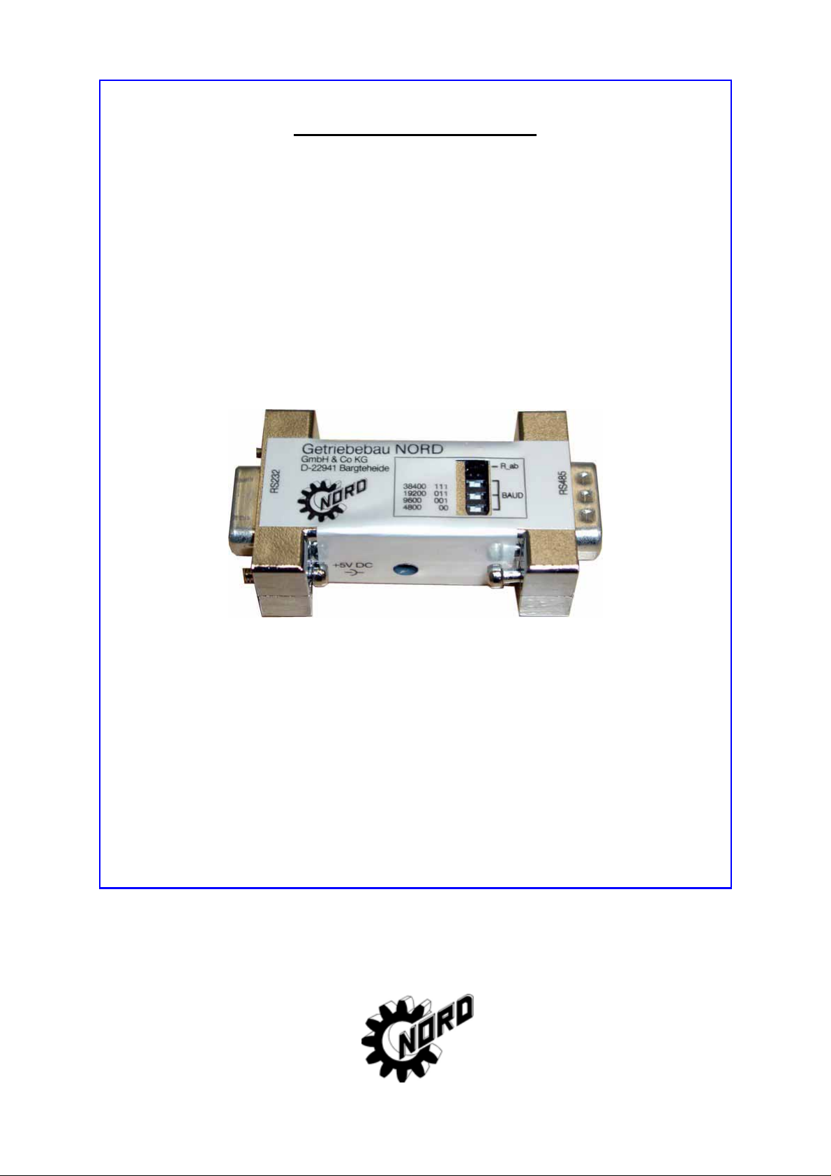
The interface converter SK IC1-232/485 converts signals from
RS485 to RS232. This converter is used when connecting a PC
or laptop to a NORDAC frequency inverter. With the aid of
NORD CON software the frequency inverter can be operated
and assigned parameters. In addition to this, the software
provides a user-friendly diagnosis tool with oscilloscope function
to ensure optimisation of drive solutions.
Depending on the type of NORDAC frequency inverter, a suitable connecting cable will be
necessary to connect the frequency inverter to the interface converter (see Overview P.4). The
converter is directly plugged into the RS232 port of the PC/laptop with its SUB-D socket. An
LED displays when the +5V supply voltage is on. The converter can be supplied from the
respective frequency inverter or the PC (USB port).
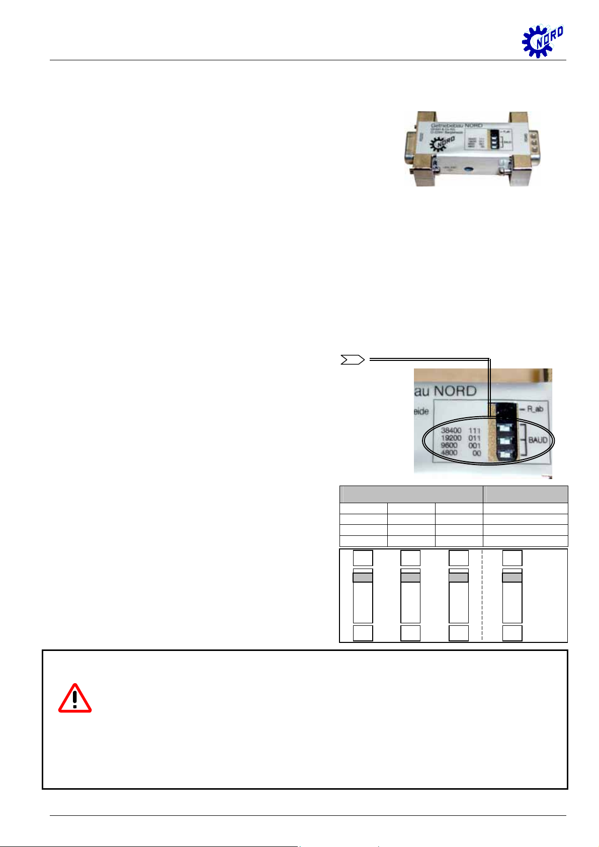
Setting the baud rate
The baud rate can be set with a combination of 3 dip
switches in the range from 4800 to 38400 bit/s and
must be adjusted to the setting of the frequency
inverter. The standard setting is 38400 bit/s, which
enables the fastest data transfer. This also
corresponds to the standard setting of the frequency
inverter. The combination for the respective baud
rate is shown on the converter. Switching state “1”
corresponds to dip switch position “ON”.
If disturbances should occur in the transfer, this is
caused by too long a cable length or too high a baud
rate. The connection should be checked using a
DIP-switch combination baud-rate
1 1 1 38400 Baud
1 1 0 19200 Baud
1 0 0 9600 Baud
0 0 0 4800 Baud
ON
ON
ON
ON
lower transfer rate. For this, the setting of the
frequency inverter in parameter P511 must also be
observed.
1
2
3
terminalresistor
R_off
4
Warning:
• The interface converter is not potential separated. The PC and/or frequency
inverter is not therefore spared the effects of a short-circuit!!!
• It must be ensured that the interface converter is connected to only one 5V
supply voltage. This may only be supplied either from the frequency inverter
or from the “external 5V supply cable” !!!
2 Technical design subject to change BU 0010 GB
Page 3
NORDAC SK IC1-232/485 Operating Instruction
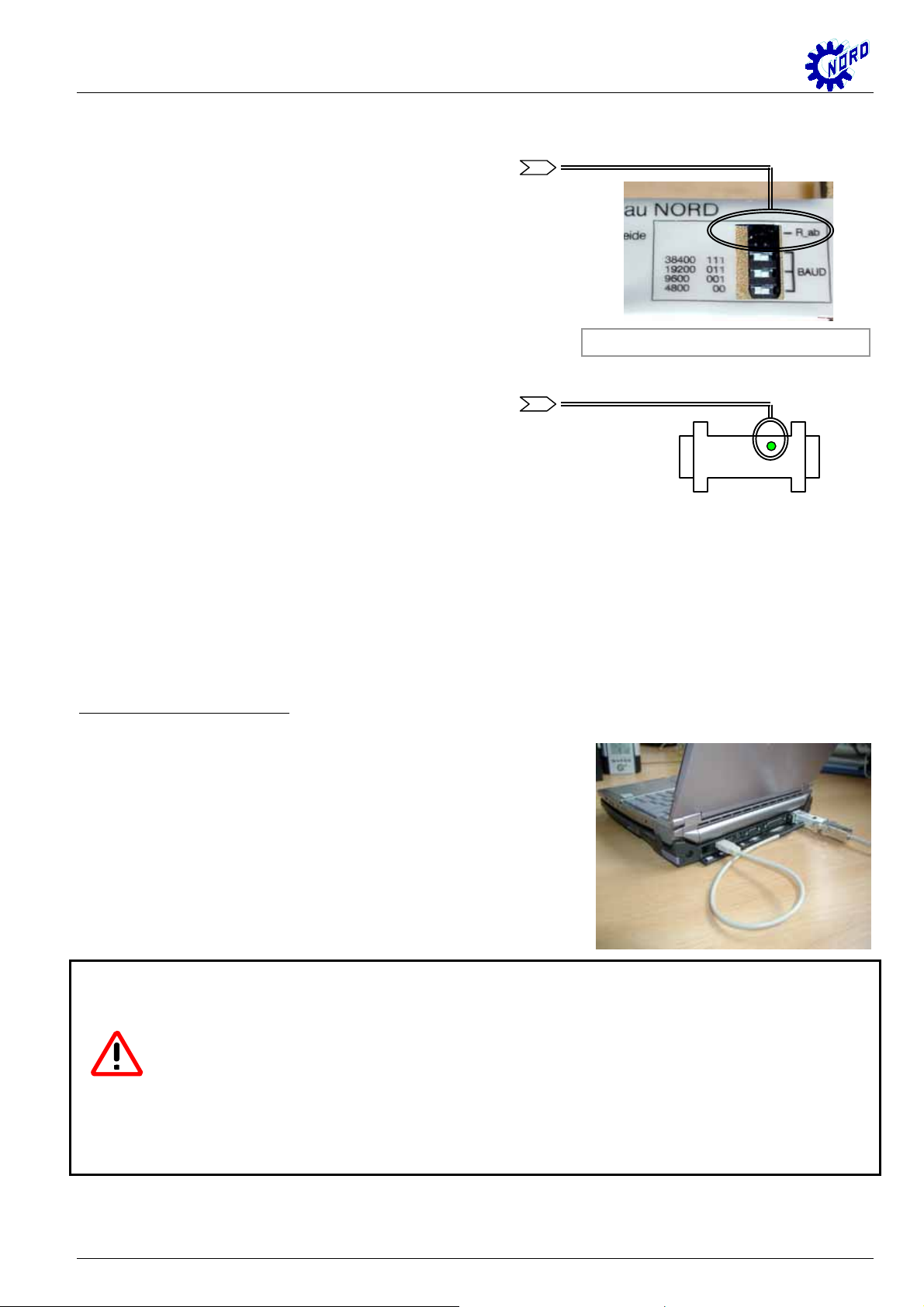
Terminal resistor
A terminal resistor can be switched on at the
interface converter using a dip switch. This terminal
resistor is switched off as default setting. The dip
switch position “ON” corresponds to a switched-on
terminal resistor of 120 Ω.
(DIP switch Æ See Figure P. 2)
“ON” position Æ See label DIP switch
Supply voltage status
As soon as the +5V supply v oltage of the interface
connector is on, this status is displayed by a green
LED.
(Current consumption of the converter: 100mA)
Information
The channel switching of ‘send’ and ‘receive’ occurs automatically.
Accessories
External supply cable 5V:
A +5V supply voltage is required for connecting the p-box to
a PC/laptop in combination with the interface converter. This
can be provided by an additional connecting cable. The
cable is connected to the USB port of the PC/laptop.
When using the interface converter on the frequency
inverter, this takes its supply voltage directly from the
frequency inverter and does not therefore have to be
supplied externally.
Attention:
It is important to ensure that there is only one supply voltage for the interface
converter. Otherwise this can cause damage !!!
When using the frequency inverters vector mc, SK 300E and SK 700E a supply
voltage of +5V is already available. An external supply cable for the USB connection
is not required in this case.
BU 0010 GB Technical design subject to change 3
Page 4

NORDAC SK IC1-232/485 Operating Instruction
Connection options for the frequency inverter to the PC or laptop for operation with NORDCON :
PC / LapTop interface converter connecting cable optional module frequency inverter
NORD CON
Software
Connecting cable 300E
3,0 m
(Mat. No.: 276970020)
5
9
RS 232
2 = RXD
3 = TXD
5 = GND
1
6
1
6
RS 485
1 = RS 485+
4 = RS 4855 = GND
6 = + 5V
5
9
permanent connection:
(Mat. No.: 278910060)
connecting cable vector
3,0 m
(Mat. No.: 278910020)
Connecting cable RS232
2,0 m
No interface converter is required here, as an RS232 signal is
present!!!
(Mat. No.: 278910030)
+ 5V/+15V
RS 485 RS 485 +
GND
(yellow)
(brown)
(white)
(green)
optional module for
frequency inverter:
vector mc:
RS232 mc
SK 700E:
SK TU1-RS2
trio SK 300E
vector mc
SK 700E
4 Technical design subject to change BU 0010 GB
 Loading...