

Page 1

Operating Instructions
ASSEMBLY UNITS VG
Page 2

System overview
1
Z - types
U - types
Gear flange
Gear
pedestal
Helical
Gearbox
Agitator
Gearbox
Warm
Gearbox
Bevel
Gearbox
Helical Shaft
Mount. Gears
2
Page 3

Contents
System overview 2
Contents 3
1 General 4
1.1 How to use the Operating Instructions 4
1.1.1 Terms used 4
1.2 Delivery 4
BERGES
1.3
1.3.1 Identification 5
1.3.2 Use as intended 5
1.3.3 Legal provisions 5/6
assembly units
2 Safety information 7
2.1 Persons responsible for safety 7
2.2 General safety information 8
2.3 Conventions used for safety information 9
3 Technical data 10
3.1 Product characteristics 10
3.1.1 Mechanical construction 10
3.1.2 General description 11
3.1.3 Mode of operation 11
3.2 Operating conditions 11
Figures 3 and 4 12
Figures 5 and 6 13
RGAE
5
4 Installation 14
4.1 Incoming inspection and transportation 14
4.2 Storage 14
4.3 Assembly 14
4.3.1 Preparations after a long storage period 14
RGAE
General information on assembly of
4.3.2
4.4 Electrical connection 15
4.4.1 Connection the main motor 15
4.4.2 Connection the variable-speed motor (electrical remote adjustment) 16
4.4.3 Connection the rev-counter 17
variable-speed drives
14/15
5 Commissioning 18
5.1 Before commissioning 18
5.2 During operation 18
5.3 Placing out of operating 19
5.4 Operation 19
6 Servicing and maintenance 20
6.1 Serving intervals 20
6.2 Serving work 20
6.2.1 Changing the Wide V-belt 20/21
6.2.2 Setting the output speed 21-23
6.2.3 Changing the variable-speed pulleys 24/25
6.2.4 Changing the bearings 25
6.2.5 General maintenance 25
7 Troubleshooting 26
8 Stocking spare parts, after-sales servicing addresses 27
8.1 Stocking spare parts 27
8.2 After-sales servicing addresses and addresses for spare parts 27
9 Manufacturer's declaration 28
10 Conformity declaration 29
3
Page 4

1 General
G
-
V
A
f
1.1 How to use these Operating Instructions
The Operating Instructions are a part of the consignment of the BERGES attach-
ments VG. They contain safety information that must be followed. Conse quently, always keep the Op. Inst. near to the VG.
Caution! The only way to achieve safe, trouble - free operation, by avoiding
operating errors and incorrect use of the V
throughly amiliar with the Op. Inst.It is thus important that the Op.
Inst. have been read and understood by those responsible for trans-
portation installation and operation and that all aspects contained
therein be followed.
We are unable to assume liability for damage,l oss, injury
or operating malfunctions resulting from non-compliance
with the information in the Operating Instruction !
Please contact our plant schould you have any technical questions:
General
, is to read and be
BERGES Antriebstechnik GmbH & Co.KG
Postfach 1140
Industriestrasse 13
D - 51709 Marienheide
Tel. : 0 22 64 / 17 - 0
Fax. : 0 22 64 / 17 125
E - mail : info_ban@berges.de
1.1.1 Terms used
In the text, BERGES attachements
In the text, BERGES Operating Instructions VG are reffered to as Op. Inst.
for short.
1.2 Scope of delivery
The VG are assembled individually on the basis of the modolar system.
Please refer to the related accompanying documents for the scope of delivery.
G are referred to as VG for short.
fter receipt of the consignment, please check immediatelythat the scope o
delivery corresponds to the accompanying documents.
4
Page 5

1.3 BERGES assembly units
G
y
G
G
1.3.1 Identification
BERGES assembly units are uniquely identified by the information on the rating
plate.
When used in hazardous areas: II 2 G D c T4 135°C
Manufacturer:
BERGES ANTRIEBSTECHNIK GMBH & CO.KG
POSTFACH 1140
INDUSTRIESTRAßE 13
D - 51709 MARIENHEIDE
TELEFON ( 02264 ) 17- 0
TELEFAX ( 02264 ) 17 125
1.3.2 Use as intended
General
BERGES - V
- are destined for use in the commercial sector in machinery and installations
- may be used only for the purposes ordered and confirmed
- may be operated only under the operating conditions prescribed in these Opera ting Instructions.
- may not be operated outside of the stipulated performance limits
Differing operating conditions will require new contractual agreements.
1.3.3 Legal provisions
Liabilit
The drives described in the Op. Inst.and the information, data and instructions
provided comply with the state of the art on the date of going to print.
No claims with respect to RGAEalready delivered may be asserted from the information, illustrations and descriptions.
We are unable to assume liability for damage, loss, injury or malfunctions resul-
ting from:
- improper use
- arbitrary modifictions to the V
- incorrect work carried out on and with the V
- operating errors
- non-compliance with the operating instructions
5
Page 6

A
General
We reserve the right to make modifications to the drives in the interests of
technical improvement and in order to enhance safety.
The Op. Inst.may not be duplicated nor used for the purposes of competition in
unauthorised manner or made available to third parties without our prior consent.
mendements or supplements to the Op. Inst. may be made solely by us; vio -
lation of this clause will result in all warranty claims being null and void.
Copyright to these Op. Inst.is retained by:
BERGES Antriebstechnik GmbH & Co. KG
Note:
Please refer to the other supplied Operating Instructions for reduction gears,
motors and optional extras such as electrical remote control etc.
Terms of warranty
Please refer to the Terms of Sale and Delivery of
BERGES Antriebstechnik GmbH & Co.KG, Marienheide.
Warranty claims must be reported to
BERGES Antriebstechnik GmbH & Co. KG, Marienheide
Warranty shall become null and void in all cases in which no liability claims can be
asserted either.
6
Page 7

2 Safety Information
2.1 Persons reponsible for safety
User
The user is any natural person or legal entity whd or which uses the VGor on
whose behalf/on behalf of which the VGare used.
The user resp. his Security Officer shall guarantee:
- that all relevant regulations, instructions and laws are complied with.
- that only qualified personnel work on and with the VG.
- that the personnel has available the Operating Instructions when carrying out any
corresponding work on and with the VG.
- that non-qualified personnel are forbidden to work on and with the VG.
Safety information
Qualified personnel
Qualified personnel are persons who, on the basis of their training, experience,
instruction and knowledge of relevant standards and regulations, accident prevention
regulations and operating conditions, have been authorised by the person responsible
for system eafety to perform the relevant, required activities and who, when doing this,
are able to recognise and avoid the possible risks and dangers.
( Definition of qualified personnel in accordance with IEC 364 )
7
Page 8

2.2 General safety information
This safety information does not claim to be complete. Please contact the reponsible
BERGES company should you have any questions or problems.
The VG comply with the state of the art on the date of delivery and are always
delivered in a safe operating condition.
The VG may be used and operated only within the framework of the conditions
stipulated in the Performance and Supply Contract.
The VG pose risks and dangers to persons, to the VG themselves and to
other valuables of the user if:
- non-qualified personnel work on and with the VG or
- the VG are used inappropriately.
The VG must be planned such that they perform their function and cause no risk
or danger to persons if they they perform their function correctly after having been
properly installed and if used as intended. This also applies to interworking thereof
with the overall installation.
The VG may be installed, placed into operation, serviced and, if necessary, re -
paired only by authorised, trained and instructed qualified personnel. ( see point 2.1
for definition of qualified personnel ).
Suitable measures must be taken to ensure that no damage to property occurs
should the VG fail.
Operate the VG only in proper working order.
All work on the VG must be performed carefully with a view to safetyand may
only ever be carried out at 'standstill'. In this case, the drive must be locked to prevent 'unintentional swich-on'( e.g. by locking the key-operated swich or removing
the fuses from the power supply ). An information sign indicating that work is underway on the drive must be attached to the 'swich-on point'.
Always follow the relevant regulations on work safety and environmental protection
during transport, assembly, dismantling, operation, care and servicing.
Rotating operating components such as couplings, gearwheels, such as increased
operating temperature or gear noises, occur during operation.
The VG must be shut down immediately should changes, such as increased
operating temperature or gear noises, occur during operation.
When installing the VG in equipment or installations, the manufacturer of the
equipment or installations is obliged tu include the regulations, instructions and
descriptions contained in these Op. Inst.in his own Operating Instructions.
On an account may retrofitting operations, modifictions or conversion work be carried
out on the VG; such work will always require consultation with BERGES
Antriebstechnik.
Safety information
Do not adjust the RGAE when stopped ( at standstill ) !
8
Page 9
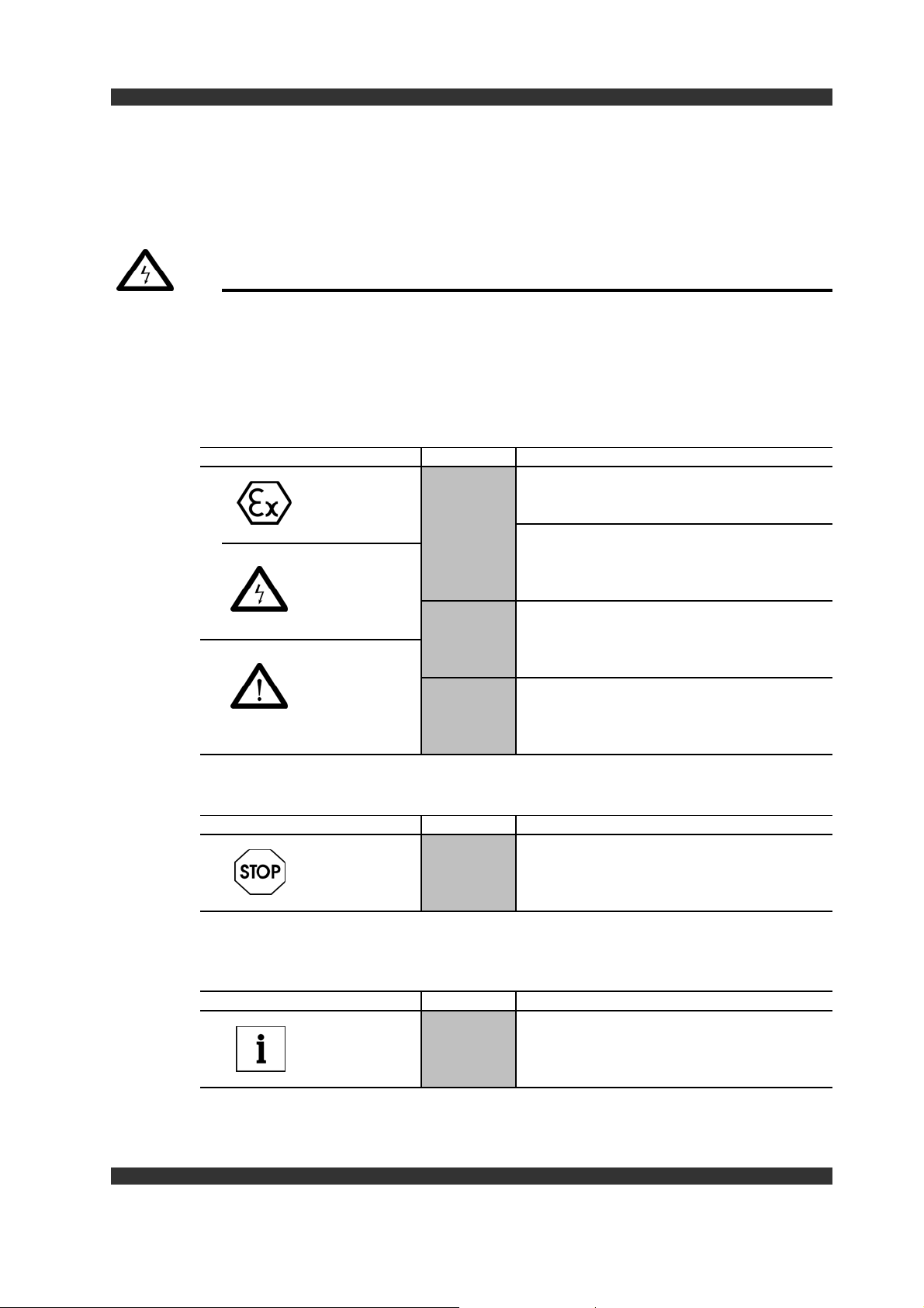
2.3 Conventions used for safety information
All safety information in these Operating Instructions has a uniform structure
Signal word
Information text
- The pictogramm identifies the type of danger
- The signal word identifies the severity of the danger
- The information text describes the danger and provides
information on how to avoid the danger
Warning against personal injury
Pictograms used Signal words
Warning of
explosive Consequences if not followed:
atmospheres Death or very serous injury.
Danger!
Warning against
hazardous
electrical
Voltage
Warning against Possible consequences if not followed:
a general danger Death or very serous injury.
Warning!
Caution!
Warns against directly imminent danger.
Warns against a possible very dangerous
situation.
Warns against a possible very dangerous
situation.
Possible consequences if not followed:
Minor or slight injury.
Safety information
Warning against damage to property
Pictograms used Signal words
Stop!
Other information
Pictograms used Signal words
Tip!
Warns against possible damage to property.
Possible consequences if not followed:
Damage to the RGAE or ist environment
Identifies a general, useful tip.
If you follow this tip, this will make your work with
the RGAE easier.
9
Page 10

3 Technical Data
yp
The most important technical data is specified on the rating plate. This data and the
contractual agreements for the drives stipulate the limits to use as intended.
Please refer to the product catalogues fo further technical data.
On complete gears ( RGAE with reduction gear and motor ), three rating plates are
normally attached. One rating plate is attached to the motor, one is attached to the
gear and one attached to the RGAE.
Technical Data
KB-Nr. = Sales order number
Type = z.B. RGAE 4/210
(1) does only apply for use in hazardoes areas
3.1 Product characteristics
3.1.1 Mechanical construction
BERGES VG are constructed on the basis of the modular system.
They consist of:
T
No.
i
n1/n2
M2max
Schmierstoff - siehe Wartungsanleitung
Lubricant - see maintenance instructions
Lubrifiant - voir instructions d'entretien
1
2
3
4
5
6
1 Type ( type of construction, size )
2 Date of manufacture
3 Gear number
4 Transmission ratio i
5 Output speeds n in rpm
6 Max. torque in Nm
(1)
7
II 2 G D c T4 135°C
1/min
Nm
BERGES assembly units VG
Output flanges or output bases GFL or GTF
Gear boxes ( helical -, worm -, bevel - and helical shaft mount. Gearboxes )
Three-phase motors to IEC standard
Speed controls SS, WS, HS, EFV or EFH
Speed indicators DVM 120 D1 or FFA 96
Caution ! The variable-speed geared motors may be operated only at the frequen-
cy specified on the rating plate.
10
Page 11

3.1.2 General description
The RGAE are supplied as a variable-speed gear attachment unit, of base or flange
design, or with reduction gear and are suitable for all conventional installation positions.
The variable-speed gear casings consits of aluminium and have a symmetrical
design. They are sturdy, vibration-damping and designed for continuous operation.
The variable-speed pulleys ( regulating and spring pulley R and F ) have a wedge-
shaped symmetrical cross-section with a very low mass.
All shafts are mounted in rolling-contact bearings and are packed with rolling-contact
bearing grease for lifetime lubrication.
The reduction gearboxes are adequately dimensioned helical -, worm-, bevel - or
helical shaft mount. Gearboxes or contrate worm gears of base, flange or hollow-shaft
design. The rugged cast casings are vibration-damping and suitable for rough industrial use.
The variable-speed gearboxes normally require no additional cooling. Venti-
lation slots and the large surface area suffice to dissipate the heat loss if convection
is unobstructed.
Technical Data
3.1.3 Mode of operation
( see Figures 3 and 4, Page 12 )
The three-phase motor ( Item 8 ) drives the mechanically adjustable regulation pulley
R ( Item 1 ). This drives the spring-loaded spring pulley F ( Item 2 ) which is arranged
on the drive shaft of the gear flange GFL ( Item 7 resp. Item 7.1, Figure 5, Page 13 )
or the drive shaft of the reduction gear ( Item 5 ), via the wide V-belt ( Item 6 ). Depen-
ding on gearbox type, the gearbox is attached either directly to one of the two casing
halves ( Item 3 / Item 4 ) or using the gear flange GFL resp. Gear base GTF.
( Item 7.1 resp. 7.2 )
The rotational speed is adjusted by the adjustment device ( Items 10, 11, 12 ) by
shiftingthe moving running surface of the mechanically adjustable regulating pulley R
in axial direction by turning the handwheel resp. Operating the variable-speed motor.
A rotational speed indication ( option ) is provided by the position indicator in the
scale handwheel or electrically by means of the pulse generator and indictor.
3.2 Operating conditions
The operating conditions, such as temperature ranges and installation altitudes, are
defined by the drive motor and the reduction gearbox ( see the relevant Operating
Instruction ). The max. permitted operating temperature of the variable-speed drive
is 80°C at normal operation and an ambient temperature of -20°C to +40°C to be
measured at the outside of the VG housing.
11
Page 12

Figure 3 BERGES Variable Speed Gear VG mounting position U
Technical Data
Figure.4
BERGES Variable Speed Gear VG, mounting position Z
12
Page 13

g
Motor flange
Gear flange
Technical Data
Figure 5 BERGES ASSEMBLY UNITS RGAE
Gear base
Item 7.2
Gear
flan
Pos.7.1
e
Figure 6
BERGES ASSEMBLY UNITS RGAE ( with Base a. FLANGE )
13
Page 14

4 Installation
4.1 Incoming inspection and transportation
The consignment must be examined immediately on arrival for completeness and
transport damage. We are able to replace damage equipment free of charge only if
an advice of damage is drawn up in the presence of the haulage contractor.
Caution !
Use only slinging equipment with a adequate load-carrying capacity to transport the
drive. Ensure that the equipment is correctly secured. Avoid shocks and jolts.
Important !
Equipment of Z - type of construction is not stable! Ensure that such equipment is
appropriatly supported.
4.2 Storage
Drives which are not be installed immediately must be covered and stored in dry
rooms not subject to major temperature differences and in the position of normal use.
Important !
Do not store drives in the open air. ( Should it be necessary to store drives in the
open air, carefully cover the drive and protect it against moisture and soiling ).
Installation
Exposed flange surfaces and shaft ends are preserved as standard, and we provide
6 months warranty on this preservation. The warranty period commences on the date
of delivery.
If the equipment is to be stored for longer than three months, remove the wide V-belt.
If the equipment is to be stored for longer than six months, inspect the preservation
and renew it if necessary.
4.3 Assembly
4.3.1 Preparations after a long stotage period
If the equipment has been stored for a long period, the output shafts and steel flange
surfaces must be cleaned to remove all traces of corrosion inhibitor.
4.3.2
General information on installation of variable speed drives VG
Always follow the safety information in Chapter 2 "Safety information" when
starting installation.
- Disconnect the machine from the electrical mains and ensure that the drive cannot
operate and that all machine movements are prevented.
- Check that the VG are in proper working order. Never operate damaged VG.
- Check the assignment of the drive function to the machine function and the direc tion of rotation.
14
Page 15

Installation
As early as the planning stage, ensure that the space provided is adequte for the
drive soas to be able to perform installation, care and sirvicing work unhindered.
The mounting areas on which the VGare to be fitted must be level, torsionally
resistant and free of vibration. ( levelness ≤ 0,1 mm )
Align the VGon the mounting surface precisly in line with the machine shaft to be
driven.
Ensure that the units are mounted free of stresses and strain so as to avoid additio-
nal loading.
Compensate for minor irregularities ( alignment and angular errors ) by using suitable,
flexible couplings.
Take appropriate measures to absorb reaction torques.
Lock mounting points for accessories and attachments and mounting points for the
VG themselves appropriatly to prevent the mounting and attachments points
loosening.
Caution !
Use suitable mounting tools or extractors to perform installation and dismantling
work on drive and output elements such as belt pulleys, sprocket wheels, running
wheels or gear wheels and couplings etc. on the gear shafts. On no account may
the part to be fitted be forced onto the shaft by hammering.
Prolonged exposure to sunshine may lead to overheating of the drive.
Provide corresponding guards. No welding work may be carried out on
the drive and the drives may not be used as grounding points for welding work.
The variable speed gears should be used in the designated mounting position, only
Stop!
The lubricant filling quantity of the gears is determined by the installation position.
Always comply with the installation position specified on the rating plate in order to
avoid gear damage.
Caution !
The RGAE of Z design are not stable and must thus be supported approprialely for
installation - until securely attached.
4.4 Electrical connection
Danger !
Electrical connection work must be carried out by a qualified electrician.
The variable speed gear must be suitably earthed.
4.4.1 Connection the main motor
The main motor of the VG must be connected in accordance with the information
in the terminal box of the motor and in the separate Motor Operating Instructions.
Always note the technical data on the motor rating plate ( Item 8.1 ). ( see also Fi gure 3 and Figure 4 , Page 12 ).
15
Page 16

4.4.2 Connection of the electrical remote control motor
Stop!
The motor of the electrical remote control may be operated only with the main motor
operating.
1. Connect the motor in accordance with the circuit diagram (Figure 7).
2. Check the direction of rotation in inching mode:
- Briefly press button S1; the operating pin must move towards the bolt-on flange.
- Briefly press button S2; the operating pin must move in the opposite direction.
- If the directions are incorrect, reverse the polarity of the motor.
3. Checking the function of the limit switches:
- Acutate limit switch S3 ( n
- Acutate limit switch S4 ( n
- The operating pin may not move in either of the two cases.
) and briefly press button S1.
2 max
) and briefly press button S2.
2 min
Installation
Figure 7
Connect.diagr.for electr.remote control
F1
K1, K2
Fuse
Combined switching contactor
for pha.reversal ( clockwise or
counter clockwise rotation of
the motor )
M1
Q1
Q2
S1
S2
S3
S4
1
2
3
4
Motor
Master switch
Motor protection switch
Pushbutton switch "Faster"
Pushbutton switch "Slower"
Limit switch
( upper speed limitation )
Limit switch
( lower speed limitation )
Drive motor ( main motor )
Control phase of drive motor
faster
slower
16
Page 17

4.4.3 Connection of the rev-counter
The electrical rev-counter is an option and can be retrofitted at any time. The rev -
counter is supplied with a connection cable. This is connected user-specifically - if
using an indicator provided by the customer - or in accordance with the regulations
for the BERGES indicator.
Pulse encoder
The rotational speed is measured without physical contact using a rotating perforated
disc which simultaneously serves to secure the spring pulley and stationary pulse
encoder.
The pulse encoder generates a digital signal in conjunction with a NAMUR input.
Installation
Suitable BERGES indicators:
Digital indicator unit DVM 120 D1
- for supply voltage 24V-DC / 230V-AC Connection - 2m PVC-cable 2x0.14
Digital indicator unit DA4 / EX- 40
- for supply voltage 24V-DC / 230V-AC Contr. circuits DIN 19234 resp. Namur
in connection with a isolating transformer and Rated voltage 10V
a frequency current transformer. Sensing dist. 0......1,62 mm
Analogue indicator FFA 96
- for supply voltage 24V-DC / 230V-AC * with angle connector
Technical Data pulse encoder:
Housing High-grade steel, stainless
cable *
EMV to EN 60947 - 5 - 2
2x 0,34mm
2
Figure 8 Pulse encoder
1
Pulse encoder
2
Connection cable 2m
( optionally 5m )
3
Perforated disc
4
Securing nut
( incremental encoder )
5
Fan cover
6
Securing screw
(perforated disc a.Fpulley )
1. Insert the collar of the perforated disc
( Item 3 )
into the bore of the spring pulley
and secure it with the securing screw ( Item 6 ) in the output shaft.
2. Screw the pulse encoder
3. Set the measuring gap: Screw the pulse encoder
forated disc
( Item 3 ) ,
( Item 1 )
into the ventilation cover
turn it back one turn ( sensing distance approx. 1 mm )
( Item 1 )
( Item 5 ).
fully against the per-
and lock with the nut ( Item 4 ) with respect to the ventilation cover ( Item 5 ).
4. Pulse meter to be turned back 2 revolutions (clearance distance about 2 mm)
Caution !
Ensure that the pulse encoder ( Item 1 ) is not screwed into a bore in the
perforated disc.
4. Install the indicator and connect it as shown in the connection diagram.
5. Adjust the reading: ( see separate Operating Instructions supplied with the
indictor ).
17
Page 18

5 Commissioning
Stop!
The drive may be commissioned only by trained specialists.
Caution !
Fit the wide V - belt beforehand if commissioning after three months ( see also
Point 4.2, Page 14 ).
5.1 Before commissioning
Caution !
Secure the drive to prevent the power supply being switched on unintentionally.
( Attach a corresponding information sign to the switch-on point )
Commissioning
Please check the following:
Is the drive properly secured mechanically ?
( Check securing bolts for firm attachment and retighten it if necessary )
Are the electrical connections ok ? ( Check the direction of rotation before
commissioning - if necessary - and reverse two phases if necessary )
On gearboxes with vent:
Has the travel plug been removed replaced by the ventilation plug ?
5.2 During Operation
Conduct regular checks and inspections during operation. Watch out particulary for
unusual noises and/or high temperatures, leaks, loose securing elements and the
condition of the electrical cables.
Should malfunctions or faults ever occur, please consult the troebleshooting table
in Chapter 7. If the fault or malfunction can still not be remedied, please inform
BERGES After-Sales Service.
Stop!
adjust the speed at standstill !
Never
Adjusting the speed at standstill
damages the RGAE !
18
Page 19

5.3 Placing out of operation
Place the drive out of operation by switching off the drive assembly.
Caution !
Lock the drive to prevent the power supply being switched on. ( Attach a corresponding information sign to the switch-on point ).
If you intend to place the drive out of operation for a long period, operate the drive
briefly every 2 weeks.If you intend to place the drive out of operation for longer than
three months, remove the wide V-belt. ( see also Point 4.2, Page 14 ).
5.4 Operation
Commissioning
Check the VG for the following during operation:
- excessive operating temperature
- changed running and gearbox noises
Caution !
If irregularities such as those described above are detected during operation, shut
down the drive assembly immediately. The cause of the fault can then be determined using the fault-finding table ( see Chapter 7 - Troubleshooting ).
Possible faults and malfunctions, their causes and suggestions for remedying the
faults are contained in the "Fault-finding table".
If you are unable to establish the cause of the fault or if the fault cannot be remedied
using your resources, please contact one of our agents or one of our plants directly.
( see corresponding addresses Page 27 )
19
Page 20

6 Servicing and maintenance
6.1 Servicing intervals
Stop!
Please complay with the servicing intervals for all drive components. ( Variable-speed
pulley, wide V-belt, gear box and motor )
Damages to the variable speed gear VG should be avoided.
Check for damages regulary.
Variable - speed pulleys and spring pulleys feature at lifetime grease lubrication
system and thus require virtually no maintenance. However, it is advisable to clean
the drive on the occasion of general machine cleaning ( inspection ). Shorter cleaning intervals will be required if soiling is heavier.
Wide V-belts are subject to natural wear:
- Inspect the wide V-belts occasionally for wear, fractures and cracks and exchange
or replace them if necessary.
- Belts should be replaced every 6.000 working houres.
Servicing
6.2 Servicing work
6.2.1 Changing the wide V-belt
Stop!
Should it be necessary to replace the belt, please use only original BERGES
wide V-belts, Type CW-B!
Berges Wide V- Belts are antistatic according to ISO 1813
Removal procedure for U version ( see also Figure 3, Page 12 )
1. Switch on the drive and accelerate it to maximum output speed. Then switch
off the drive and disconnect it from the mains.
2. Undo the casing voltage connections ( Item 3.1 ), ( 4, 6 oder 8 bolts depen-
ding on drive size ) and remove the halve of the casing ( Item 4 ).
3. Fully open variable-speed pulley R ( Item 1 ) and detach the wide V-belt ( Item6 )
over the front edge of the variable-speed pulley R ( Item1 ) and by turning the
variable-speed pulley and spring pulley by hand.
Removal procedure for Z version ( see also Figure 4, Page 12 )
1. Switch on the drive and accelerate it to maximum output speed. Then switch
off the drive and disconnect it from the mauns.
2. Undo the casing connections ( Item 3.1 ), ( 4, 6 or 8 bolts depending on drive
size ), move the half of the casing ( Item 3 ) adequately away from the other half
of the casing ( Item 4 ), whilst supporting the three-phase motor ( Item 8 ), to
allow the wide V-belt ( Item 6 ) to be detached from the variable-speed pulley R
( Item 1 ).
20
Page 21

Servicing
Fitting U and Z version ( see also Figures 3 and 4, Page 12 )
1. First fit the new wide V-belt into the spring-loaded spring pulley F ( Item 2 ) and
thread it up by hand and then fit it into the fully-open mechanically adjustable
variable-Speed pulley R ( Item 1 ). Turn the drive by hand until the belt is taut.
2. Bolt the halves of the housing ( Items 3 und 4 ) back together ( 4, 6 or 8
bolted connections )
3. Conduct a trial run. When doing this, check the speed limits and the setting
of the speed indicators using a hand-held rev-counter. It may be necessary to
readjust the setting owing to allowable wide V- belt length tolerances ( see
see Chapter 6.2.2, Page 21 - 23 ).
Tip! U version, Figure 9
On sizes RGAE4 to 9, the spring pulley F ( Item 2 ) can be opened by screwing a
bolt into the main hub flange against spring pressure. The wide V-belt can then be
fitted first into the open spring pulley F ( Item 2 ) and then into the open variable speed pulley R ( Item 1 ). Follow the reverse procedure when removing.
Caution!
Always remove the bolt again after fitting and prior to placing into operation.
Figure 9 Spring pulley F
Item 1 Only on sizes 4 - 9
Required bolt dimensions :
DIN 933
Size 4/210 M5 x 45
Size 5/250 M5 x 55
Size 5/280 M6 x 70
Size 6/300 M8 x 70
Size 6/350 M8 x 70
Size 7/375 M8 x 80
Size 7/400 M8 x 80
Size 8/450 M12 x 90
Size 8/500 M16 x 90
Size 9/600 M20 x 100
6.2.2 Setting the output speed
The output speed limits n
plete gears and RGAE with base / flange and mounted motor ). If there is heavy
wear orafter changing the wide V-belt, it may be necessary to readjust the speed
limits in line with the information on the rating plate ( Item 8.1, Figures 3 and 4 ).
2max
and n
are preset at the works ( only on com-
2min
21
Page 22

Servicing
Stop!
Neveradjust the speed at standstill!
Adjusting the speed at standstill damages theRGAE.
Always ensure that the wide V-belt
does not contact the base of the hub ( clearly audible, whistling running noise ).
cannot move beyond the edge of the variable-speed pulley and/or spring pulley.
Procedure in the case of electrical remote control ( Figure 7 )
1. Swich on the drive motor ( Pos.8 ).
2. First set the upper speed limit ( n
- Check the speed with the hand-held rev-counter and increase the speed to
maximum speed with button S1
- Slide the limit swich S3 against the operating pin until the operating pin can
be heard to swich.
- Firmly tighten the securing bolts of the limit swich.
2max
):
3. Then set the lower speed limit in the same way. ( Button S2 and limit swich S4 )
Procedure in the case of spindle and angle adjustment (Fig.10 and 11)
1. Swich on the drive motor ( Item 8 - Figures 3 and 4, Page 12 ).
2. Detach the bottom cover plate ( Item 4 ) on the adjustment device.
3. Adjust the drive with the handwheel ( Item 8 ) and hand - held rev -counter to
maximum speed in accordance with the rating plate ( Item 1 - Figures 3 and 4,
Page 12 ).
4. Adjust the nut ( Item 6 ) as the end limit ( self-locking nut ).
5. Set the minimum speed in the same way with the nut ( Item 5 ). (self-locking nut)
6. Reattach the cover plate ( Item 4 ).
7. Then, using the hand-held rev-counter, check that the reading of the position indi-
cator ( optional ) on the handwheel corresponds to the actual speed value or the
corresponding comparison value.
Caution! Pressure pot of the speed adjustment device must be in contact with
the bearing ring.
Pressure pot should not cause any friction at all times.
Adjusting the position indicator ( Figures 10 and 11 )
1. Undo the setscrew ( Item 7 ) and remove the scale insert ( Item 9 ).
2. Turn the scale insert ( Item 9 ) until the reading corresponds to the actual value
or comparison value.
3. Reinsert the scale insert ( Item 9 ) into the handwheel and lock it with the set -
screw ( Item 7 ).
22
Page 23

Figure 10 Spindle adjustment SS
4
Cover plate
5
Securing bolt
6
Nut
7
Setscrew
8
Handwheel
9
Scale insert
Servicing
Figure 11 Angle adjustment WS
Cover plate
4
5
Securing belt
6
Nut
7
Tetscrew
8
Handwheel
9
Scale insert
Drawn 90° - offset
23
Page 24

6.2.3 Changing the variable-speed pulleys
Installing the variable-speed and spring pulley ( Figure 12 )
The pulley bores are manufactures to DIN 7154, fit H7. The dimensions of the spli -
nes comply with DIN 6885, Sheet 1 (3) and the tolerance also complies with fit H7.
The variable - speed pulleys must be fitted on the drive and output shafts with a sli ding fit (do not use force, e.g. by hammering).
Never fit too tight since, otherwise, the main hub would expand in the bore and
prevent the sliding pulley halves ( 2 and 3 ) sliding.
Caution!
The moving pulley halves ( Items 2 and 3 ) of both variable - speed pulleys must
always be diagonally opposed. ( See Figure 12 )
Figure 12
Servicing
Axial locking of the variable-speed pulleys ( Figure 13 )
The pulleys must be mounted as shown in Figure 13. This type of mounting affords
two essential advantages:
- there are no rotating parts projecting outside of the pulley
- the attachment system also be used as an extractor device. ( see Figure 14 )
The attachment discs ( Item 5 ) are designed in accordance with Works Standard in
line with the threads in the drive and output shafts to DIN 332 - Sheet 2.
Figure 13
24
Page 25

Servicing
Removing the variable-speed and spring pulleys ( Figure14 )
The variable-speed and spring pulleys can be removed by removing the cheese-head
screw ( Item 6 ), the spring washer ( Item 8 ), the securing disc ( Item 5 ) and the
circlip (Item 7) from the bore. Place a smooth disc (Item 9 ) in front of the shaft stub
in order to protect the shaft thread, guide the attachment disc ( Item 5 ) the other
way around into the bore and press the circlip ( Item 7 ) back into the recess of the
bore. The variable-speed and spring pulley can now be removed from the shaft by
screwing in a hexagon - head screw ( Item 10 ). The thread in the securing disc
( Item 5 ) is always "one size" larger than the corresponding shaft thread.
Figure 14
Alignment ( Figure 15 )
The variable-speed pulley and spring pulley must be "precisely aligned", the wide
V-belt may not "run skew". This extremely important precondition for proper ope-
ration of the drive is met if the stop shoulders of drive and output are aligned.( Owing
to permissible belt length tolerances, a slight correction may be necessary by fitting
corresponding spacer rings behind when changing the wide V-belt).
6.2.4
6.2.5
Figure 15
Changing the bearings
The bearings of the mechanical pulleys and gearbox flanges schould be replaced
if excessively noisy and certainly within 90% of a bearings theoretical life.
Pulley type / GFL
R080b - R300b 40.000
R350b - R400b 20.000
R500b - R600b 13.000
GFL 1 - GFL 7 10000*
*Values apply to maximum speeds, without talking into consideration the load applied by the customer.
General Maintenance
90%-theor.Lagerlebensdauer
Betriebsstunden
Regular cleaning must be carried out on the ventilation slots and the interior of the
variable speed gear to prevent the accomulation of dirt. The penetration of abrasive
dusts must be avoided.
25
Page 26

7 Troubleshooting
If faults or malfunctions occur when operating the BERGES attachments VG,
please check the possible causes of the fault on the basis of the table below.
If the fault cannot be remedied by any of the measures listed in the table or if the
fault which has occurred is not attributable to one of the causes specified in the
table please inform one of the BERGES service addresses.( See Service adresses,
Chapter 8, Page 27 )
Caution!
If faults necessitating repair of the VG occurs during the warranty period, such
faults may be remedied only by BERGES After-Sales Service. We advise you to
enlist the services of our After-Sales Servicing Department even if faults whose
cause cannot be clearly determined occur after the warranty period has expired.
Faults Possible cause Remedy
The drive does not start Main motor not connected or
connected incorrectly
Clearly audible running noise of Wide V-belt contacting base Set speed limitation correctly
the variable-speed drive of hub
Changing running noises of the Bearing defective Replace dfective bearings ( Consult
reduction gear After-Sales Sevicing Department )
Troubleshooting
Check motor connection
Excessive bearing play Set bearing play ( Consult After-
Sales Department )
Execssive external loading of Correct loading to nominal data
drive or output
Rotational speeds specified on Speed limitation not correctly Set speed limitation correctly
the rating plate are not being set stellen
reached
Incorrect wide V-belt fitted Fit correct wide V-belt ( See related
accompanying documents )
Indication of scale insert incorrect Scale insert incorrectly fitted Fit scale insert at max. set output
speed
Motor of the electrical remote Motor not connected or Check motor connection
control does not turning connected incorrectly
Adjustment spindle blocked Clear blockage with centring thread
of the motor of the electrical remote
control or turn the fan impeller
VG overheating
Drop in speed or torque
Drive starts sluggishly or not Output subject to hight loading Correct loading to nominal loading
at all
Fan cowl of the drive motor and/ Clean fan cowl, motor, fan cover
or VG heavily fouled and surface of VG
Belt tension of the VG too
low - wide V-belt worn
Guide of variable-speed and/or Replace variable-speed and/or
spring pulley worn spring pulley
Fit a new wide V-belt
26
Page 27

Service
8
Stocking spare parts, after-sales servicing adresses
8.1 Stocking spare parts
We advise you to stock the most important spare parts and parts subject to wear
with a view to maintaining the VGconstantly ready for operation.
We provide warranty only for original spare parts supplied by us.
Caution!
We must expressly point out that only the spare parts and accessories supplied
by ushave also been inspected and approved by us. Use and/or installation of third-
party parts and third-party accessories may have a negative effect or influence design
characteristics of the VG and thus impair active and/or passive safety. BERGES
Antriebstechnik & Co. KG cannot be held liable and is unable to accept any
claims under warranty for damage and loss resulting from the use of non - original
spare parts and accessories.
Please note that spare parts and accessories are frequently subject to special manu-
facturing specifictions and engineering specifications for delivery and that we always
offer and supply in accordance with the most recent state of the art and most recent
legislation.
Please always state the following when submitting orders for spare parts.
KB - Nr. ( see rating plate )
Type designation ( see rating plate )
Part-No. (Item No. From spare parts or 8-digit article No. )
Quantity
8.2 Sales and Service adresses
BERGES Antriebstechnik GmbH & Co.KG
Industriestraße 13 Unit 3, Nelson Business Centre,
D-51709 Marienheide Nelson Street, Denton
Tel. ( 0 22 64 ) 17 - 0 GB-Manchester M34 3EY
Fax. ( 0 22 64 ) 1 71 25 Tel. ( 01 61 ) 3 35 09 95
BERGES Italiana s.r.l.
Industriestraße 11 24035 Research Drive
I-39025 Naturns / Bz. Farmington Hills, Michigan 48335
Tel. ( 04 73 ) 67 19 11 USA
Fax. ( 04 73 ) 67 19 09 Tel. ( 8 10 ) 4 78-82 50
BERGES Antriebstechnik AG
Postfach 48
CH-8853 Lachen
Tel. ( 04 73 ) 67 19 11
Fax. ( 04 73 ) 67 19 09
BERGES (UK) Ltd.
Fax. ( 01 61 ) 3 35 09 35
BERGES NORTH AMERICA
Fax. ( 8 10 ) 4 78-05 68
Variable Speed Gears VG
Nr. 40.001.00.01
24.11.2003
27
Page 28

9 Manufacturer's declaration
Manufacturer's declaration
As defined by the EC - Machinery Directive 98/37/EEC, Annex II B
We hereby declare that the
Variable Speed Gears VG
VG 1/80 ....... RGAE 9/600
described in these Operating Instructions are destined for installation in a machine or
assembly to form a machine and that they may not be placed into operation until it has
been determined that the machine in which the VG are to be installed complies with
the provisions of EC Directive 98/37/EG ( original version ).
Manufacturer's declarations
This Manufacturer's Declaration allows, either wholly or in part, for all Harmonised
Standards relating to our products and published by the EC Commission in the
Official Gazette of the European Community.
EN 292 - 1
EN 292 - 2
EN 294
EN 349
EN 60204 - 1
BERGES - Antriebstechnik
GmbH & Co. KG
Manufacturer's signature:
Information on the signatory: ( Company Management )
Date: 24. November 2003
B E R G E S . . . e v e r y t h i n g u n d e r c o n t r o l .
28
Page 29

Conformity declarations
10 CONFORMITY DECLARATION
EG-Konformitätserklärung
EG-Declaration of Conformity
Berges Antriebstechnik GmbH & Co. KG erklärt, dass Verstellgetriebe
der Typen VG1 - VG9 mit der
Berges Antriebstechnik GmbH & Co. KG certifies herewith, that the variable speed
gears type VG1 - VG9 comply with the
Explosionsschutzrichtlinie 94/9/EG übereinstimmen.
EC Directive 94/9/EG for explosion-proof
Zündschutzart für Gerätegruppe II der Kategorie 2 und 3:
Protection type for apparatus group II of the categories 2 and 3:
EX II 2 G D c T4 135°C EX II 3 G D c T4 135°C
Angewandte Normen : • EN 1127 - 1 • EN 13463 - 1 • pr EN 13463 - 5
Applied standards : • EN 1127 - 1 • EN 13463 - 1 • pr EN 13463 - 5
Die technische Dokumentation für Getriebe der Kategorie 2 ist hinterlegt
bei der benannten Stelle TÜV PRODUKT SERVICE GmbH
Ridlerstraße 31, D-80339 München.
The technical documentation for gears of the category 2 has been lodged
at the named authority TÜV PRODUCT SERVICE GmbH
Ridlerstraße 31, D-80339 München.
BERGES - Antriebstechnik
GmbH & Co. KG
Hersteller-Unterschrift :
Angaben zum Unterzeichner : ( Geschäftsleitung )
Datum :
24. November 2003
B E R G E S . . . e v e r y t h i n g u n d e r c o n t r o l .
29
 Loading...