

Page 1

Intelligent Drivesystems, Worldwide Services
GB
B2050
Operating and Maintenance Instructions for Explosion Protected
Industrial Gear Units SK 72 07 - SK 155 07
DRIVESYSTEMS
Page 2

Page 3
1.
Notes ................................................................................................................................ 4
1.1 General information .......................................................................................................... 4
1.2 Safety and information symbols ........................................................................................ 4
1.3 Correct use ....................................................................................................................... 4
1.4 Safety information ............................................................................................................. 5
1.5 Other documents .............................................................................................................. 5
1.6 Disposal ............................................................................................................................ 6
2. Description of gear units ............................................................................................... 7
2.1 Type designations and gear unit types ............................................................................. 7
3. Storage, transport, preparation, installation ................................................................ 8
3.1 Storing the gear unit.......................................................................................................... 8
3.2 Long-term storage ............................................................................................................. 8
3.3 Inspecting the drive unit .................................................................................................... 9
3.4 Checking the name plate data .......................................................................................... 9
3.5 Checking the configuration ............................................................................................. 11
3.6 Transporting the gear unit ............................................................................................... 11
3.7 Preparing for installation ................................................................................................. 14
3.8 Installing the gear unit ..................................................................................................... 15
3.9 Fitting hubs on the gear shafts ....................................................................................... 16
3.10 Fitting push-on gear units ............................................................................................... 17
3.11 Torque support ................................................................................................................ 19
3.12 Fitting shrink discs .......................................................................................................... 20
3.13 Fitting the covers ............................................................................................................. 21
3.14 Fitting a standard motor .................................................................................................. 22
3.15 Subsequent paintwork .................................................................................................... 23
3.16 Temperature sticker ........................................................................................................ 24
3.17 Mounting the external cooling system (cooling unit) ....................................................... 25
4. Commissioning ............................................................................................................. 27
4.1 Check the oil level ........................................................................................................... 27
4.2 Lubricant cooling using an external cooling system (cooling unit) ................................. 28
4.3 Operation with pressure circulation lubrication ............................................................... 29
4.4 Pressure safeguard......................................................................................................... 29
4.5 Operation with back stop ................................................................................................ 30
4.6 Temperature measurement ............................................................................................ 31
4.7 Checking the gear unit .................................................................................................... 32
4.8 Checklist ......................................................................................................................... 32
4.9 Operation of the gear unit in explosive areas ................................................................. 33
5. Service and maintenance ............................................................................................. 34
5.1 Service and Maintenance Intervals ................................................................................. 34
5.2 Service and Maintenance Work ...................................................................................... 34
6. Appendix ........................................................................................................................ 39
6.1 Versions and maintenance ............................................................................................. 39
6.2 Lubricant quantities ......................................................................................................... 41
6.3 Lubricants ....................................................................................................................... 43
6.4 Torque values ................................................................................................................. 44
6.5 Troubleshooting .............................................................................................................. 45
6.6 Declaration of Conformity ............................................................................................... 46
Table of Contents
www.nord.com B2050-GB-0613 -3-
Page 4
1. Notes
1.1 General information
Read the Operating Manual carefully prior to performing any work on or putting the gear unit into
operation. Strict compliance with the instructions in this Operating Manual is essential. This
Operating Manual and all associated special documentation must be kept in the immediate
vicinity of the gear unit.
Getriebebau NORD accepts no liability for damage to persons, materials or assets as a result of
the non-observance of this Operating Manual, operating errors or incorrect use.
If additional components are attached to or installed in the gear unit (e.g. motor, cooling
system, pressure sensor etc.) or components (e.g. cooling system) are supplied with the
order, the operating instructions for these components must be observed.
If you do not understand the contents of this Operating Manual or additional operating
instructions, please consult Getriebebau NORD!
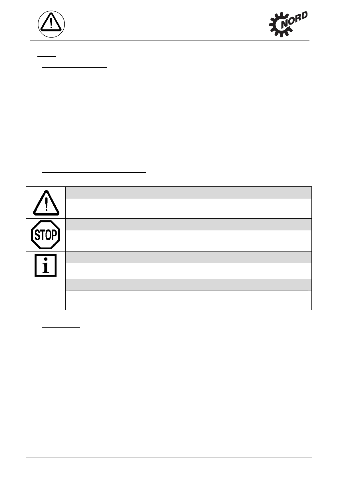
1.2 Safety and information symbols
Please always observe the following safety and information symbols!
Danger!
1. Notes
Risk of fatalities and injury
Attention!
Machine may be damaged
Note!
Useful information
Danger!
Important information regarding explosion protection
1.3 Correct use
These gear units generate a rotational movement and are intended for use in commercial
systems. They satisfy the explosion-proof requirements of Directive 94/9EG (ATEX100a) for the
product category indicated on the name plate.
Strict compliance with the technical data on the name plate is essential.
The documentation must be observed.
Appropriate safety measures must be taken for applications where failure of a gear unit or
geared motor may result in injury.
Only components which comply with the applicable regulations of Directive 94/9/EU may be
fitted and operated.
-4- B2050-GB-0613 www.nord.com
Page 5
1.4 Safety information
Danger!
All work including transportation, storage, installation, electrical connection,
commissioning, servicing and maintenance must be performed in a non-explosive
atmosphere.
All work including transportation, storage, installation, electrical connection, commissioning,
servicing, maintenance and repair must be performed only by qualified specialist personnel.
It is recommended that repairs to NORD Products are carried out by the NORD Service
department.
Danger!
Installation and maintenance work must only be performed when gear units are at a
standstill and have cooled down. The drive must be isolated and secured to prevent
accidental start-up.
Tighten the drive elements or secure the parallel key before switching on.
1. Notes
Observe all safety information, including that provided in the individual sections of this
Operating Manual. All national and other regulations on safety and accident prevention must
also be observed.
Danger!
Serious physical and property damage may result from inappropriate installation, nondesignated use, incorrect operation, non-compliance with safety information,
unauthorised removal of housing components or safety covers and structural
modifications to the gear unit.
1.5 Other documents
Further information may be obtained from the following documents:
Gear Unit Catalogue (G1050)
Operating and maintenance instructions for the electric motor
If applicable, the operating instructions for options and drive units which are fitted or
provided.
www.nord.com B2050-GB-0613 -5-
Page 6
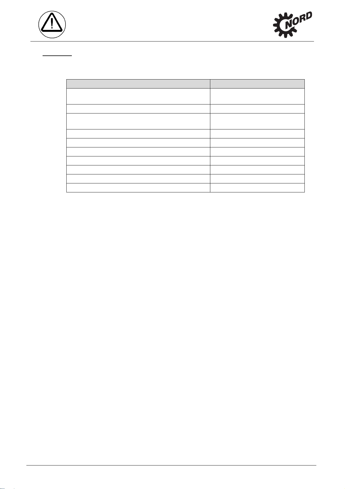
1.6 Disposal
Observe the current local regulations. In particular, lubricants must be collected and dispose d of
correctly.
Gear unit components: Material:
Toothed wheels, shafts, rolling bearings, parallel keys,
locking rings, …
Gear unit housing, housing components, … Grey cast iron
Light alloy gear unit housing, light alloy gear unit
housing components, …
Worm gears, bushes, ... Bronze
Radial seals, sealing caps, rubber components,… Elastomers with steel
Coupling components Plastic with steel
Flat seals Asbestos-free sealing material
Gear oil Additive mineral oil
Synthetic gear oil (name plate code: CLP PG) Polyglycol-based lubricants
Cooling spiral, screw fittings Copper, yellow brass
1. Notes
Steel
Aluminium
-6- B2050-GB-0613 www.nord.com
Page 7
V
2. Description of gear units
2. Description of gear units
2.1 Type designations and gear unit types
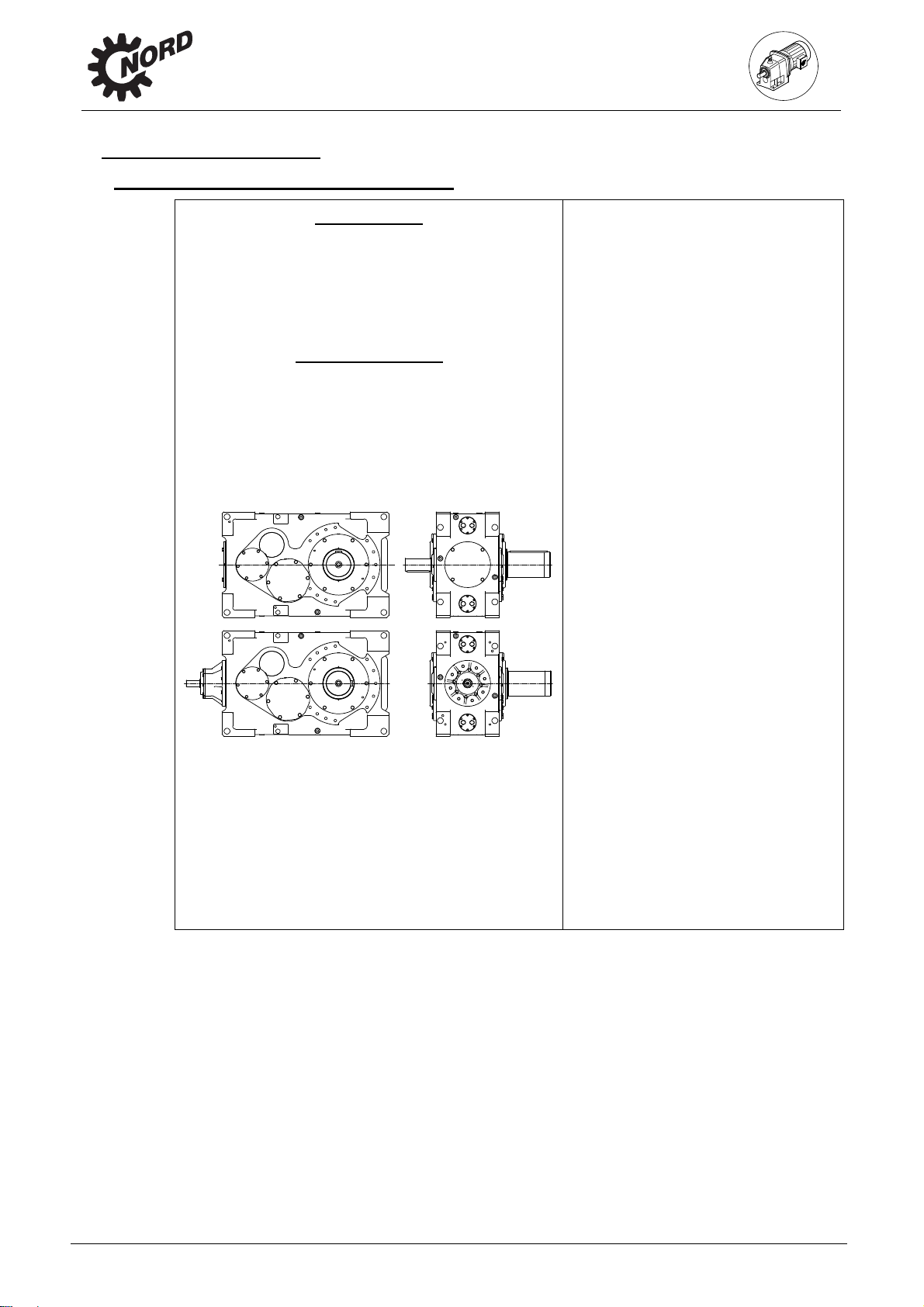
Helical gear unit
SK 7207, SK 8207, SK 9207, SK 10207
SK 11207, SK 12207, SK 13207, SK 15207
(2-stage)
SK 7307, SK 8307, SK 9307, SK 10307
SK 11307, SK 12307, SK 13307, SK 15307
(3-stage)
Bevel helical gear unit
SK 7407, SK 8407, SK 9407, SK 10407
SK 11407, SK 12407, SK 13407, SK 15407
(3-stage)
SK 7507, SK 8507, SK 9507, SK 10507
SK 11507, SK 12507, SK 13507, SK 15507
(4-stage)
ersions / Options
- Foot mounting with solid shaft
A Hollow shaft version
B Fixing element
CS2 Cooling system oil / air
D Torque support
EA Hollow shaft with internal spline
ED Elastic torque support
EV Solid shaft with internal spline
EW Drive shaft with internal spline
F Block flange
FAN Fan
FK Collar flange
F1 Drive flange
H Covering cap as contact guard
IEC Standard IEC motor attachment
L Solid shaft both sides
MF.. Motor base frame
…B with brake
…K with elastic coupling
…T with hydrodynamic coupling
MS.. Motor swing base
…B with brake
…K with elastic coupling
…T with hydrodynamic coupling
NEMA Standard NEMA motor attachment
S Shrink disc
V Solid shaft
VL Reinforced bearings
VL2 Agitator design
VL3 Drywell agitator design
W Free drive shaft
W2 Two drive shaft journals
W3 Three drive shaft journals
Double gear units consist of two single gear units. Gear units SK11207 – SK15507 are to be
treated according to these instructions and attached gear units are to be treated according to the
operation and maintenance instructions B2000, each as two individual gear units. Type
designation of double gear units: e.g. SK13307/7282 (consisting of single gears SK13307 and
SK 7282).
www.nord.com B2050-GB-0613 -7-
Page 8
3. Assembly instruction,
3. Storage, transport, preparation, installation
3.1 Storing the gear unit
For short-term storage before commissioning, please observe the following:
Store in the fitting position (see Section 6.1) and secure gear units against falling
Lightly grease bare metal housing surfaces and shafts
Store in dry rooms
Temperature in the range from –5
Relative humidity less than 60%
No direct exposure to sunlight or UV light
No aggressive, corrosive substances (contaminated air, ozone, gases, solvents, acids,
No vibration or oscillation
3.2 Long-term storage
storage, transport, preparation, installation
o
C to +50 oC without large fluctuations
alkalis, salts, radioactivity etc.) in the immediate vicinity
Note!
For storage or standstill periods in excess of 9 months, Getriebebau NORD
recommends the long-term storage option. With the long-term storage option and the
use of the measures listed below, storage for up to 2 years is possible. As the actual
influences on the unit greatly depend on the local conditions, these times should only
be regarded as guide values.
Conditions of the gear unit and storage area for long-term storage prior to
commissioning:
Store in the fitting position (see Section 6.1) and secure gear units against falling
Transportation damage to the external paint must be repaired. Check that a suitable rust
inhibitor is applied to the flange bearing surfaces. If necessary apply a suitable rust inhibitor
to the surfaces.
Gear units with the long-term storage option are completely filled with lubricant or have VCI
corrosion protection agents added to the gear oil. (See label on gear unit)
The sealing band in the vent plug must not be removed during storage. The gear unit must
remain sealed tight.
Store in a dry place.
In tropical regions, the drive unit must be protected against damage by insects
Temperature in the range from –5
o
C to +40 oC without large fluctuations
Relative humidity less than 60%
No direct exposure to sunlight or UV light
No aggressive, corrosive substances (contaminated air, ozone, gases, solvents, acids,
alkalis, salts, radioactivity etc.) in the immediate vicinity
No vibration or oscillation
Measures during storage or standstill periods
If the relative humidity is <50% the gear unit can be stored for up to 3 years.
-8- B2050-GB-0613 www.nord.com
Page 9
Measures before commissioning
If the storage or standstill period exceeds 2 years or the temperature during short-term
If the gear unit is completely filled, the oil level must be reduced before commissioning.
storage, transport, preparation, installation
storage greatly deviates from the standard range, the lubricant in the gear unit must be
replaced before commissioning.
3.3 Inspecting the drive unit
Danger!
The drive unit must be inspected and may only be installed if:
No damage, e.g. due to storage or transport is apparent. In particular the shaft
sealing rings, the sealing caps and the covers must be inspected for damage.
No leakage or no oil loss is visible.
No corrosion or other indications of incorrect or damp storage is apparent.
The packaging material has been completely removed.
3. Assembly instruction,
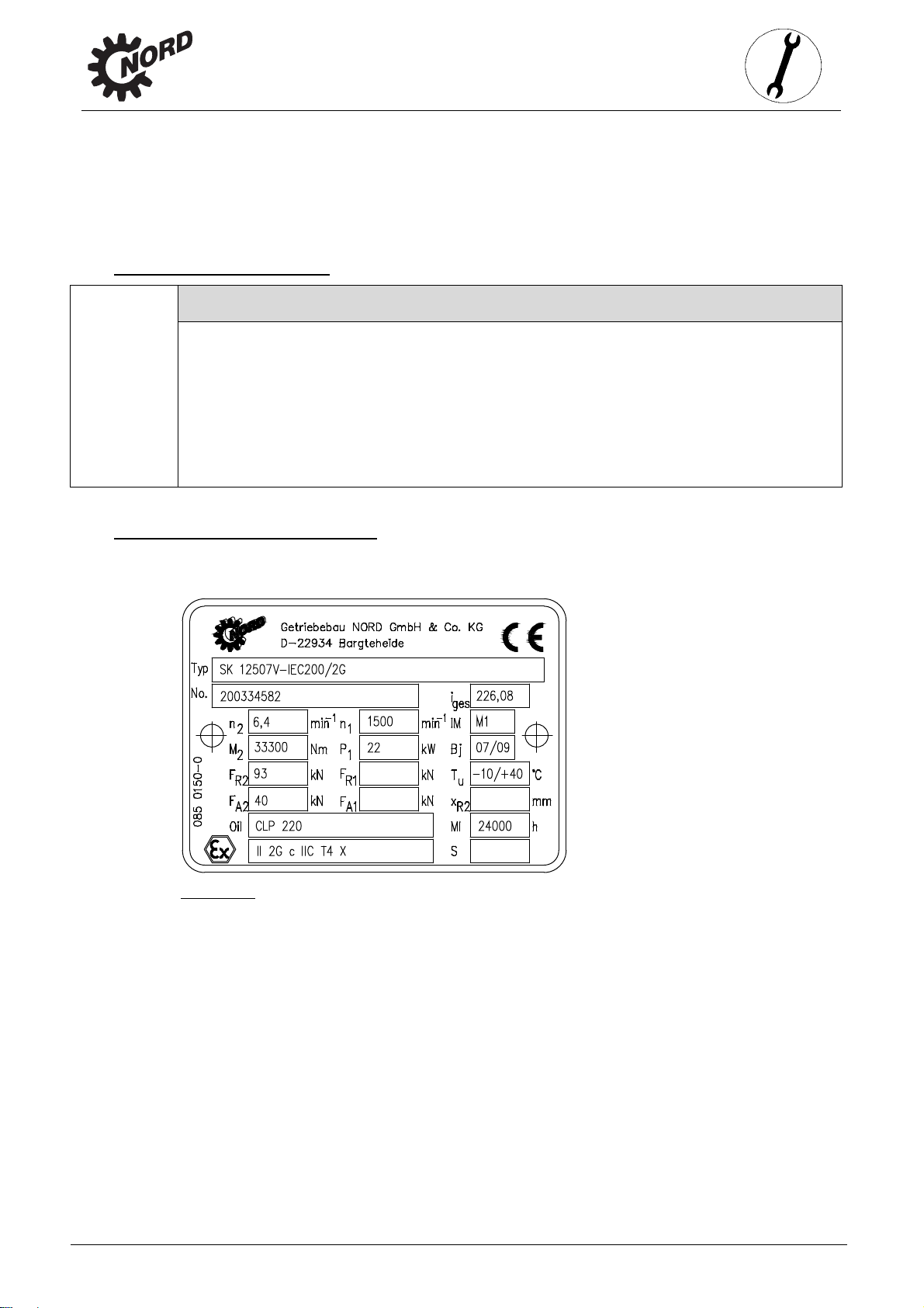
3.4 Checking the name plate data
The name plate must be firmly attached to the gear unit and must not be subjected to permanent
soiling. Please contact the NORD service department if the name plate is illegible or damaged.
Figure 3-1: Name Plate (example)
www.nord.com B2050-GB-0613 -9-
Page 10
3. Assembly instruction,
Explanation of the name plate
Abbreviation Unit Name Refer to
Type - NORD gear unit type
No. - Serial number
i
- Overall gear unit ratio
ges
storage, transport, preparation, installation
n2
n1
IM - Configuration (installation orientation) Sec. 6.1
M2 Nm Max. permissible gear unit drive shaft torque
P1 kW Max. permissible drive power or motor power
Bj - Year of manufacture
FR2 kN Max. permissible transverse force on the gear unit driven shaft Sec. 3.9
FR1 kN Max. permissible transverse force on the gear unit drive shaft for option W Sec. 3.9
Tu °C Permissible ambient temperature for the gear unit
FA2 kN Max. permissible axial force on the gear unit driven shaft Sec. 3.9
FA1 kN Max. permissible axial force on the gear unit drive shaft for option W Sec. 3.9
MI h Interval between general overhauls of the gear unit in operating hours
xR2 mm Max. dimension for the point of application of the transverse force FR2 Sec. 3.9
Oil - Gear unit oil type (standard designation) Sec. 6.3
min-1
min-1
Rated speed of gear unit drive shaft*
Rated speed of the gear unit drive shaft or the drive motor*
or details of the non-dimensional maintenance class CM
Sec. 5.2
Sec. 5.2
Last line
S - Number of the special documentation, consisting of serial no. / year
* The maximum permissible speeds are 10% above the rated speed, if the maximum permissible drive power
P1 is not exceeded.
If the fields FR1, FR2, FA1 und FA2 are empty, the forces are zero. If the field xR2 is empty, the point of
application of force F
-
Labelling as per ATEX (DIN EN 13463-1):
1. Group (always II, not for mines)
2. Category (2G, 3G for gas or 2D, 3D for dust)
3. Ignition protection type if fitted (c)
4. Explosion group if applicable (IIC, IIB)
5. Temperature class (T1-T3 or T4 for gas) or max. surface
temperature (e.g. 125°C for dust) or
special max. surface temperature see special documentation (TX)
6. Temperature measurement on commissioning (X)
is central on the drive shaft journal (See Figure 3-7).
R2
Sec. 4.6
-10- B2050-GB-0613 www.nord.com
Page 11
3. Assembly instruction,
Danger!
It must be checked and ensured that the gear unit type, all technical data and the ATEX
labelling conform to the planning of the plant or the machine.
Please note that for geared motors (gear units with attached electric motors) the electric motor
has its own name plate and separate ATEX designation. The motor labelling must also comply
with data for the planning of the plant or the machine. The lowest explosion protection of the
gear unit and the motor labelling applies for the geared motor unit. If the electric motor is driven
with a frequency inverter, the motor requires ATEX approval for inverter operation.
3.5 Checking the configuration
Danger!
The gear unit may only be operated in the stated configuration. The permissible
configuration is stated on the name plate (IM…). If an X is present in the field IM, the
special documentation, whose number is in field S, must be observed. Section 6.1, or
the special documentation, shows the configuration of the individual types of gear
units. It must be checked and ensured that the configuration as stated on the name
plate complies with the installation orientation and that the installation orientation does
not change during operation.
storage, transport, preparation, installation
3.6 Transporting the gear unit
Danger!
To prevent injury, the danger area must be generously cordoned off. Standing under
the gear unit during transport is extremely dangerous.
Attention!
Avoid damage to the gear unit. Impacts to the free ends of the shafts may cause
internal damage to the gear unit.
Use adequately dimensioned and suitable means of transportation. Lifting tackle must
be designed for the weight of the gear unit. The weight of the gear unit can be obtained
from the dispatch documents.
The gear unit should remain on the transport packaging during transportation. It must be
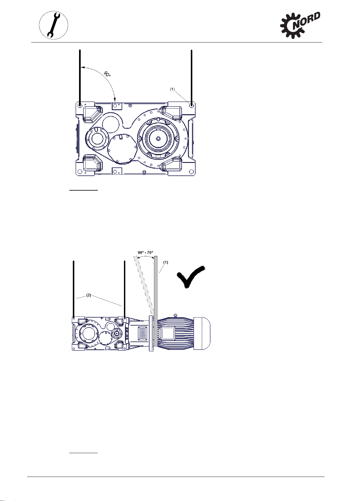
transported without oil. Only the four ring bolts (1) (See Figure 3-2) provided may be used for
transporting the gear unit. For additional drive units and components, an additional lifting point
may be necessary. The ends of the shafts must not be used for transportation, as this may
seriously damage the gear unit. The ring bolts screwed into the gear unit must be used for
transportation. If geared motors have an additional eyebolt attached to the motor, this must not
be used. When lifting with the ring bolts, there must be no oblique force.
www.nord.com B2050-GB-0613 -11-
Page 12
3. Assembly instruction,
storage, transport, preparation, installation
Figure 3-2: Gear unit lifting points
For additional drive units and components, an additional lifting point may be necessary.
Gear units with motor adapter
Gear units with a motor adapter may only be transported with lifting ropes (2) and chains or
lifting straps (1) at an angle of 90° to 70° to the horizontal. The ring bolts on the motor must not
be used for transportation.
Figure 3-3: Transport of gear unit with motor
-12- B2050-GB-0613 www.nord.com
Page 13
3. Assembly instruction,
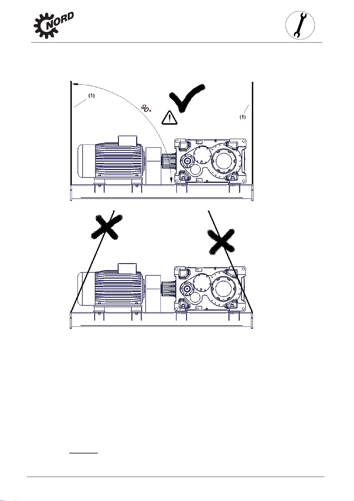
Gear units on motor swing base or base frame
Gear units on a motor swing base or base frame must only be transported with vertically
tensioned lifting ropes (1) or chains.
storage, transport, preparation, installation
Figure 3-4: Transport of gear unit with motor swing base or base frame
www.nord.com B2050-GB-0613 -13-
Page 14
storage, transport, preparation, installation
3.7 Preparing for installation
The drive unit must be inspected and may only be installed if no transportation damage or leaks
are visible. In particular the radial seals and the sealing caps must be inspected for damage.
All bare metal surfaces and shafts of the gear unit are protected against corrosion with oil,
grease or corrosion protection agents before shipping.
Thoroughly remove all oil, grease or corrosion protection agents and any dirt from the shafts and
flange surfaces before assembly.
Danger!
Care must be taken that drive elements attached to the gear unit, such as clutches,
pulleys etc. and drive motors are also ATEX-compliant.
Attention!
Gear units and geared motors are filled with oil as standard when delivered from the
factory. For filling, the lubricant stated on the name plate must be used. Please refer to
section 6.2 for the amount of lubricant.
As an option, the gear unit can be filled with lubricant.
In all cases, the oil level must be checked as per Section 4.1 prior to commissioning.
3. Assembly instruction,
In applications where an incorrect rotational direction may result in damage or potential risk, the
correct rotational direction of the drive shaft is to be established by test running the drive when
uncoupled and guaranteeing such for subsequent operation.
Attention!
Gears with integrated return stops are marked with arrows on the driven/driving sides.
The arrows point in the rotation direction of the gear unit. It must be ensured, when
connecting the motor and during motor control, that the gear unit can only operate in
the rotation direction, e.g. by means of a rotary field test. Switching of the motor into
the blocked direction of rotation, i.e. the wrong direction of rotation may cause damage
to the gear unit.
Ensure that no aggressive or corrosive substances are present in the area surrounding the
installation site or are subsequently expected during operation, which attack metal, lubricants or
elastomers. In case of doubt, please contact Getriebebau NORD and take the recommended
action.
The pressure vent must be activated prior to commissioning. To activate, remove the transport
securing devices. Double gear units consist of two single units and are equipped with 2 oil
chambers and 2 pressure vents.
Figure 3-5: Activation of the pressure vent
-14- B2050-GB-0613 www.nord.com
Page 15
storage, transport, preparation, installation
3.8 Installing the gear unit
Danger!
No explosive atmosphere must be present when installing the gear unit.
The base and/or flange to which the gear unit is fitted should be vibration-free, torsionally strong
and flat. The smoothness of the mating surface on the base or flange must be according to
tolerance class K of DIN ISO 2768-2. All contamination to the bolting surfaces of gear unit and
base and/or flange must be thoroughly removed.
The base must be designed according to the weight and torque, taking into account the forces
acting on the gear unit. Bases which are insufficiently rigid may lead to radial and axial
displacement during operation, which is not measurable when the unit is stopped.
Tensioning bars must be cast into the concrete base in their aligned state.
The gear unit must be precisely aligned with the drive shaft of the machine in order to prevent
additional forces from being imposed on the gear unit due to distortion.
3. Assembly instruction,
Note!
The service life of shafts, bearings and couplings depends on the precision of
alignment of the shaft. Therefore, zero deviation should always be aimed for in
alignment. For this, e.g. the requirements for the coupling should be obtained from the
special operating instructions.
The tolerances of the shaft ends and the flange connections should be obtained from the
dimension sheet.
Welding of the gear unit is prohibited. The gear unit must not be used as the earth connection for
welding work, as this may cause damage to the bearings and gear wheels.
The gear housing must always be earthed. With geared motors, earthing via the motor
connection must be ensured.
The gear unit must be installed in the correct orientation (See Section 6.1). All gear unit
feet on each side or all flange screws must be used. Bolts must have a minimum quality of 8.8.
The bolts must be tightened to the correct torques (refer to Section 6.4 for torque values).
Tension-free bolting must be ensured, particularly for gear units with a foot and flange.
Oil checking and drain screws must be accessible.
To ensure that the gearbox does not get too warm and to avoid injury to persons, observe
the following during installation:
Danger!
The surfaces of gear units or geared motors may become hot during or shortly after
operation. Attention: danger of burns! Protection against accidental contact may need to
be installed.
www.nord.com B2050-GB-0613 -15-
Page 16

3. Assembly instruction,
Danger!
Enable the free flow of air to all sides of the gear unit.
Ensure adequate space around the gear unit.
With geared motors, the cooling air of the motor fan must be able to flow unobstructed
Do not enclose or encase the gear unit/geared motor.
Do not subject the gear unit to highly energetic radiation.
Do not direct warm exhaust air from other units onto the gear unit/geared motor.
The base or flange to which the gear unit is attached must not input any heat into the
storage, transport, preparation, installation
The cooling air supplied to the gear unit/geared motor must be within the
permissible temperature range stated on the name plate.
In case of direct sunlight falling onto the gear unit, the cooling air supplied to the
gear unit/geared motor must be at least 10°C below the highest permissible
temperature of the ambient temperature range Tu, which is stated on the name
plate.
onto the gear unit.
gear unit during operation.
Do not pile up dust in the area of the gear unit
3.9 Fitting hubs on the gear shafts
Attention!
Drive and driven elements, e.g. coupling and chain-wheel hubs must be mounted onto
the drive and driven shaft of the gear unit using suitable pullers that will not apply
damaging axial forces onto the gear unit. In particular, do not hit the hubs with a
hammer.
Note
Use the end thread of the shafts for pulling. Fitting can be aided by coating the hub
with lubricant or heating it up to approx. 100
o
C beforehand.
Figure 3-6: Example of a simple pulling device
Danger!
Drive and driven elements, such as belt drives, chain drives and couplings must be
fitted with contact protection.
-16- B2050-GB-0613 www.nord.com
Page 17

3. Assembly instruction,
Danger!
Care must be taken that drive and driven elements attached to the gear unit must also
be ATEX-compliant.
Drive and driven elements may apply to the gear unit only the maximum permitted radial
and lateral forces FR1 and FR2 and axial forces FA1 and FA2 indicated on the name plate
(see Section 3.4). Observe the correct tension, particularly on belts and chains. Additional loads
due to unbalanced hubs are not permitted.
Danger!
The radial force must be applied to the gear unit as closely as possible. For drive shafts
with free shaft ends the maximum permissible transverse force FR1 applies for the
application of the transverse force to the centre of the free shaft journal. For driven
shafts, the application of the transverse force FR2 must not exceed the dimension xR2.
If the transverse force F
dimension xR2 is stated, the application of the force is assumed to be to the centre of
the shaft journal.
storage, transport, preparation, installation
for the driven shaft is stated on the name plate, but no
R2
Figure 3-7: Permitted force applied to drive and driven shaft
3.10 Fitting push-on gear units
Attention!
The bearings, gear wheels, shafts and housing may be damaged by incorrect fitting.
The push-on gear unit must be fitted onto the shaft using a suitable puller, which will
not exert damaging axial forces on the gear unit. In particular, do not hit the gear unit
with a hammer.
Assembly and subsequent dismantling is facilitated by applying an anti-corrosive lubricant to the
shaft and the hub before fitting (e.g. Nord Anti-Corrosion Art.-No. 089 00099). Excess grease or
anti-corrosion agent may escape after assembly and may drip off. Clean these points on the
output shaft after a running-in time of approx. 24 hours. This escape of grease is not due to a
leak in the gear unit.
www.nord.com B2050-GB-0613 -17-
Page 18

3. Assembly instruction,
Figure 3-8: Applying lubricant to the shaft and the hub
Note!
The gear unit can be fitted to shafts with and without a shoulder using the fastening
element (Option B). Tighten the bolt of the fastening element to the correct torque. (See
Chapter 6.4 for torque values)
storage, transport, preparation, installation
Figure 3-9: Fasten the gear unit to the shouldered shaft using the fastening element
Figure 3-10: Fastening the gear unit to a shaft without a shoulder using the fastening element
A gear unit can be dismantled from a shaft with shoulder using the following device, for example.
Figure 3-11: Dismantling
-18- B2050-GB-0613 www.nord.com
Page 19

When assembling push-on gears with torque supports, the support must not be distorted.
Distortion-free assembly is made easier if an elastic element (Option DG) is used.
storage, transport, preparation, installation
3.11 Torque support
The length of the torque support can be adjusted within a certain range. The torque support
consists of a fork head with a bolt (1), a threaded bolt (2), a maintenance-free joint head (3) and
a fork plate with a bolt (4).
Assembly should be carried out from the side of the machine, in order to reduce the bending
moment on the machine shaft. Tension and pressure and installation upwards or downwards are
not permissible.
Distortion of the torque support during assembly or operation must be avoided, as otherwise the
service life of the output shaft bearings may be reduced. Torque supports are not suitable for the
transmission of radial forces, therefore they may only be used in combination with motor
adapters or couplings which cannot transmit radial forces.
For helical gear units with motor adapters, the torque support is located opposite to the motor
adapter.
The gear unit is aligned horizontally by means of the threaded bolt and the nuts of the torque
support and secured with lock-nuts.
3. Assembly instruction,
Tighten the bolts on the torque support to the correct torque (see Section 6.4 for torque values)
and secure to prevent loosening. (e.g. Loctite 242, Loxeal 54-03)
Figure 3-12: Permissible installation deviations of the torque support
www.nord.com B2050-GB-0613 -19-
Page 20

storage, transport, preparation, installation
3.12 Fitting shrink discs
Figure 3-13: Mounting the solid shaft with a shrink disc
3. Assembly instruction,
GREASE FREE!
Attention!
Do not tighten the tensioning screws if the shaft is not inserted!
Assembly sequence:
1. Remove any transport securing devices.
2. Loosen but do not remove tightening bolt and tighten gently by hand until there is no play
between the outer ring and the inner ring.
3. Push the shrink disc up to the collar on the hollow shaft (see Fig. 3-13). The shrink disc is
easier to slide on if the bore of the inner ring is lightly greased.
4. Prior to mounting, grease the solid shaft only in the area which will later come into contact
with the bronze bush in the hollow shaft of the gear unit. Do not grease the bronze bush, in
order to prevent grease penetrating the area around the shrink connection.
5. The hollow shaft of the gear unit must be completely de-greased and completely
free of grease.
6. In the area of the shrink connection the solid shaft of the machine must be degreased and
completely free of grease.
7. Insert the solid shaft of the machine into the hollow shaft so as to completely fill the area
around the shrink connection.
8. Tighten the bolts successively in a clockwise direction by several turns – not crosswise –
with approx. ¼ rotation per turn.
9. After tightening the tensioning bolts the face of the inner ring on the screw side must be flush
with the face of the outer ring. The distortion of the shrink disc must be checked visually.
10. The hollow shaft of the gear unit and the solid shaft of the machine should be marked with a
line (felt-tip pen) in order to detect any slippage under load.
-20- B2050-GB-0613 www.nord.com
Page 21

storage, transport, preparation, installation
Danger!
Risk of injury from incorrect mounting and dismantling procedures.
Dismantling sequence:
1. Loosen the bolts successively in a clockwise direction by several turns with approx. ¼
rotation per turn. Do not remove the bolts from their thread.
2. If the external ring does not detach from the inner ring after approx. one turn of all screws,
the external ring can be released with the aid of the push-off thread. For this, the required
number of tensioning bolts are uniformly screwed into the push-off thread until the external
ring separates from the internal ring.
3. Remove the gear unit from the solid shaft of the machine.
If a shrink plate is used for a long period or if it is contaminated, it must be dismantled, cleaned
and the conical surface (cone) treated with Molykote G-Rapid Plus or similar lubricant prior to reassembly. The treads and head surfaces of the screws must be treated with grease without
Molykote. Any damaged or corroded elements must be replaced.
3. Assembly instruction,
3.13 Fitting the covers
Danger!
Shrink discs and exposed rotating shaft ends require contact guards in order to
prevent injuries. A cover (Option H) can be used as a guard. If this does not achieve
sufficient protection against contact according to the required protection type, the
machinery and plant constructor must ensure this by means of special attached
components.
Danger!
Covers must be inspected for transportation damage e.g. dents and warping before
they are fitted. Damaged covers must not be used, as they may cause rubbing.
All fixing screws must be used and coated prior to use with a securing lubricant e.g. Loctite 242,
Loxeal 54-03 and tightened to the correct torque. (See Chapter 6.4 for torque values)
www.nord.com B2050-GB-0613 -21-
Page 22

3. Assembly instruction,
3.14 Fitting a standard motor
Danger!
Only standard motors with an adequate ATEX Zone category according to the name
plate may be used. In addition, for ATEX category 2D gear units (see the ATEX labelling
on the last line of the gear unit name plate), the motor must have at least protection
class IP6x.
Only couplings which are approved and labelled for use in explosion hazard areas may
be used. The ATEX labelling must conform to the details of the system and/or machine
design.
The maximum permitted motor weights indicated in the table below must not be exceeded when
attaching the motor to an IEC- / NEMA adapter:
storage, transport, preparation, installation
Maximum permitted motor weights
IEC motor size
NEMA
motor size
Maximum
motor weight
[kg]
IEC motor size
NEMA
motor size
Maximum
motor weight
[kg]
Transnorm
Maximum
motor weight
[kg]
63 71 80 90 100 112 132
56C 143T 145T 182T 184T 210T
25 30 40 50 60 80 100
160 180 200 225 250 280 315
250T 280T 324T 326T 365T
200 250 350 500 700 1000 1500
315 355 400 450
1500 2200 3200 4400
-22- B2050-GB-0613 www.nord.com
Page 23

w
A
3
o
r
b
s
a
t
A
t
o
h
f
e
C
t
e
o
r
p
o
o
v
t
d
t
a
n
f
i
4
t
g
s
e
n
b
f
e
e
u
k
a
e
m
r
2
r
o
o
h
o
h
L
e
e
e
a
h
r
1
a
f
m
r
q
h
g
c
,
n
t
r
a
d
u
e
h
b
s
n
o
o
M
f
t
o
o
N
l
e
c
u
m
e
7
t
o
c
s
e
ssembly p
ocedure to
torage,
ttach a sta
3. Asse
ranspo
dard moto
bly ins
t, prepa
to the IEC
truction
ation, i
dapter (Op
stallati
ion IEC)/NE
n
MA adapter
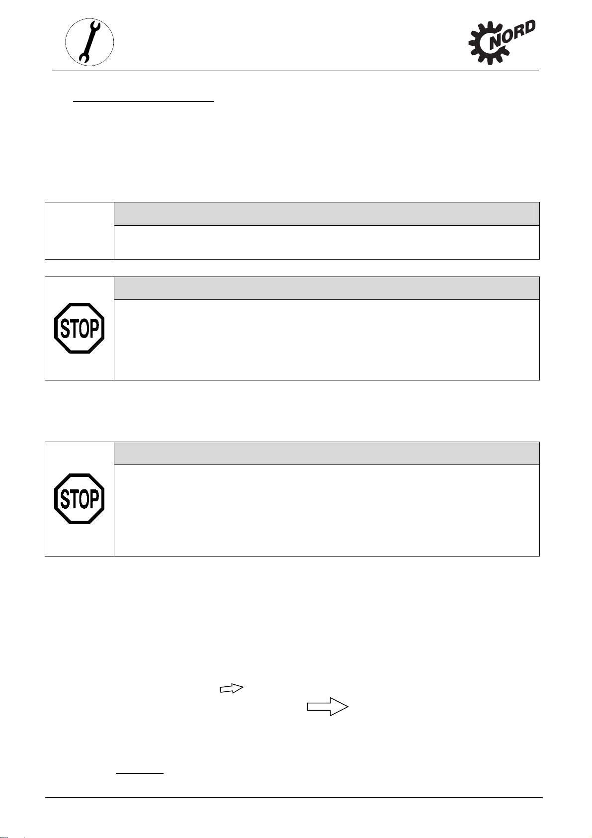
1. Clean
Moun
NEM
2. Push
the gr
3. Pull t
manu
of the
coupling. (S
4. Secur
with a
(See
5. Moun
6. Tight
motor sha
ing dimens
MG1 Part
he couplin
ove in the
e coupling
acturer. Th
the coupli
securing lu
hapter 6.4
the motor o
n the adapt
t and flang
ons and t
.
sleeve ont
leeve on tig
sleeve ont
shaft end o
e Figure 3-
g half with t
ricant e.g.
or torque va
n the adapt
r bolts to th
e surfaces
lerances o
the motor
tening.
the motor
f the motor
14)
he threaded
octite 242,
lues)
r. Do not fo
correct tor
of motor a
the moto
shaft so th
shaft accor
ust be adj
pin. The thr
Loxeal 54-0
get the ring
ue. (See C
nd adapter
must con
t the motor
ing to the
sted so tha
aded pin m
and tighte
gear
apter 6.4 fo
and check
orm to DI
parallel key
instructions
it is paralle
ust be coat
ned to the
r torque val
for damag
EN 5034
engages in
of the mot
with the fa
d prior to u
orrect torqu
es)
.
/
o
r
e
e
.
.15 Su
Figure 3-1
Attenti
The ope
sequent
Attenti
For retr
venting
must no
may be
4: Fitting th
n!
ating instr
aintwor
n!
spective p
alves, hos
come into
amaged or
coupling to
ctions for t
inting of th
s, name pl
contact wit
made illegi
the motor s
he couplin
e gear unit,
tes, adhes
paints, la
ble.
aft
must be o
the radial
ve labels a
quers or s
served.
eals, rubbe
d motor c
lvents, as
r elements,
upling co
therwise c
pressure
ponents
omponents
ww.nord.c
m
B
050-GB-06
3
-23
-
Page 24

storage, transport, preparation, installation
3.16 Temperature sticker
Danger!
With temperature class T4 gear units with a maximum surface temperature of less than
135°C the supplied self-adhesive temperature sticker (printed with value 121°C) must
be affixed to the gear unit housing. (Part No.: 8510400).
The temperature class or the maximum surface temperature can be seen from the ATEX
labelling in the last line of the name plate.
Examples: II 2G c IIC T4 X or II 3D 125 °C X
The temperature label must be attached in the area of the drive mount For gear units with an
IEC / NEMA adapter, the temperature label must be attached as for a helical gear unit.
3. Assembly instruction,
Figure 3-15: Position of the temperature label for helical and helical bevel gear units
-24- B2050-GB-0613 www.nord.com
Page 25

3. Assembly instruction,
3.17 Mounting the external cooling system (cooling unit)
Attention!
The separate manufacturer’s documentation must be observed for mounting.
Danger!
For operation in explosion hazard atmospheres, only approved and labelled cooling
systems may be used. The ATEX labelling must conform to the details of the system
and/or machine design.
Connect the cooling system according to fig. 3-16. Another connection can be agreed upon
during consultation with NORD.
storage, transport, preparation, installation
Attention!
With circulation lubrication (LC) use the connection diagram included by NORD.
(1) Suction connection gear unit
(2) Suction connection pump / cooling system
(3) Pressure connection cooling system
(4) Pressure connection gear unit
(5) Temperature monitoring (optional)
Figure 3-16: Industrial gear unit with CS1 and CS2 cooling systems
www.nord.com B2050-GB-0613 -25-
Page 26

3. Assembly instruction,
Figure 3-17: Hydraulic diagram of the industrial gear unit with CS1 and CS2 cooling systems
storage, transport, preparation, installation
-26- B2050-GB-0613 www.nord.com
Page 27

4. Commissioning
4.1 Check the oil level
Danger!
The oil level must be checked prior to commissioning.
The installation must comply with the configuration on the name plate. Section 6.1 describes the
versions and the corresponding oil level screws. With double gear units, the oil level must be
checked on both units. The pressure vent must be at the position marked in Section 6.1.
Gear unit types that are not supplied full of oil must be filled before the oil level is checked. (See
Section 5.2)
Checking the oil level:
1. The oil level may only be checked when the gear unit is at a standstill and has cooled
down. The gear unit must be secured to prevent accidental switch-on.
2. Gear units with oil level screw:
The oil level screw corresponding to the version must be screwed out. (See Section 6.1)
4. Commissioning
The oil level in the gear unit should be checked with the supplied dipstick (Part No.:283 0050)
as shown in Figure 4-1. To do this, the part of the dipstick which is submerged in the oil must
be held vertically.
The maximum oil level is the lower edge of the oil level hole.
The minimum oil level is approx. 4 mm below the lower edge of the oil level hole.
If the oil level is not correct, it must be adjusted by draining off oil or topping up with the type
of oil stated on the name plate.
If the screw lock coating in the thread of the oil drain screw or oil level screw is damaged, a
new oil level screw must be used or the thread cleaned and coated with securing adhesive,
e.g. Loctite 242, Loxeal 54-03 prior to insertion.
Check the sealing ring for damage. Replace with a new sealing ring in case of damage.
Fit the oil level screw together with the sealing ring and tighten to the correct torque. (See
Section 6.4 for torque values).
If the pressure vent has been unscrewed, reinsert it together with the sealing ring and tighten
to the correct torque. (See Section 6.4 for torque values).
3. Gear units with oil inspection glass:
The oil level can be seen directly in the window
The correct oil level is the middle of the inspection glass
If the oil level is not correct, it must be adjusted by draining off oil or topping up with the type
of oil stated on the name plate.
4. All previously removed screws must be screwed back in correctly.
www.nord.com B2050-GB-0613 -27-
Page 28

Figure 4-1: Checking the oil level with a dipstick
4. Commissioning
4.2 Lubricant cooling using an external cooling system (cooling unit)
Danger!
When commissioning the cooling system, the operating instructions of the oil /air
cooler or oil / water cooler must be observed.
Danger!
The drive unit may only be commissioned after the cooling system has been connected
and commissioned.
For operation in explosion hazard atmospheres, only approved and labelled cooling
systems may be used. The ATEX labelling must conform to the details of the system
and/or machine design.
Danger!
The temperature of the cooling water and the cooling water flow rate must be
supervised and ensured by the operator.
The ATEX approval is void if these instructions are not observed!
Attention!
The filter of the cooling system must be checked regularly (see Section 5.1).
Attention!
With oil / air coolers an adequate air intake must be ensured. The air inlet grille and the
fan blades must be kept clean.
Note!
If there is a danger of frost the operator should add a suitable anti-freeze solution to the
cooling water.
Temperature regulation can optionally be provided by using a temperature switch or a resistance
thermometer, which is installed in the oil sump of the gear unit.
-28- B2050-GB-0613 www.nord.com
Page 29

4. Commissioning
4.3 Operation with pressure circulation lubrication
Attention!
If pressure circulation lubrication is used, the operational viscosity of the gear oil on
start-up must not exceed 1800 cSt. For ISO-VG220 this corresponds to a maximum
temperature of 10℃ for mineral oil, and a temperature of at least 0℃ for synthetic oil.
Danger!
The drive unit may only be commissioned after the pump for the pressure circulation
lubrication has been connected and commissioned. Observe the operating instructions
for the pump.
For operation in explosion hazard atmospheres, only approved and labelled circulation
pumps may be used. The ATEX labelling must conform to the details of the system
and/or machine design.
During operation, the function of the lubricant circulation must be monitored and
ensured. The gear unit must be shut down immediately in case of failure of the
lubrication circulation.
All gear units equipped with lubricant circulation are provided with a pressure switch to monitor
the pump function. The connection of the pressure switch and the evaluation of the signal must
be carried out by the operator. The pressure switch must be connected so that operation is only
possible if the oil pump has built up pressure. During commissioning, a lower pressure is
permissible for a short time.
4.4 Pressure safeguard
The pressure safeguard is an electric switch, which monitors the lubrication pressure of gear
units with circulation lubrication or targeted lubrication. If the pre-set pressure is undershot, the
applied electric signal is interrupted by the pressure safeguard. Evaluate the signal accordingly.
Caution!
Connect the pressure safeguard so as to be fully functional before starting operation for the
first time. The pressure safeguard can only be used in combination with a monitoring system.
Note!
Evaluate the pressure safeguard after initially operating the pump, as pressure must be built
up.
www.nord.com B2050-GB-0613 -29-
Page 30

4.5 Operation with back stop
Optional backstops, which allow rotation in only one direction and block the other direction of
rotation are available for attachment to the gearbox. The lubrication of the backstop is by means
of the gear oil. The backstops lift off due to centrifugal force above a certain lifting speed n1 (see
table 4-1) and are then free of wear.
Danger!
In continuous operation, back stops may only be operated at above the lift-off speed.
4. Commissioning
Figure 4-2: Industrial gear unit with back stop
Gear units Stages iN Lift-off speed n1
[min-1]
SK 112 07
SK 113 07
SK 114 07
SK 115 07
SK 122 07
SK 123 07
SK 124 07
SK 125 07
SK 132 07
SK 133 07
SK 134 07
SK 135 07
SK 152 07
SK 153 07
SK 154 07
SK 155 07
Table 4-1: Lift-off speeds for back stops
2 5,6 - 20 320
3
3 12,6 - 71 1136
4
2 5,6 - 20 250
3 22,4 - 112 320
3 12,6 - 71 888
4 80 - 400 1136
2 5,6 - 20 250
3 22,4 - 112 320
3 12,6 - 71 888
4 80 - 400 1136
2 5,6 - 20 220
3 22,4 - 112 250
3 12,6 - 71 781
4 80 - 400 888
31,5 - 112 400
22,4 - 28 320
112 - 400 1420
80 - 100 1136
-30- B2050-GB-0613 www.nord.com
Page 31

4.6 Temperature measurement
The details of the ATEX temperature class or the maximum surface temperature are based on
normal installation conditions (see Section 3.7). Even small changes to the installation conditions
can have a significant effect on the temperature of the gear unit.
Danger!
On commissioning, a surface temperature measurement of the gear unit must be made
under maximum load.
(This does not apply to gear units which are labelled as temperature class T1 – T3 or a
maximum surface temperature of 200°C in the last line of the name plate.)
For the measurement, a normal temperature measuring device is required, with a measurement
range from 0°C to 130°C and a precision of at least ± 4°C and which enables the measurement
of the surface temperature and the temperature of the air. Temperature measurement
procedure:
1. Allow the gear unit to run at maximum speed under maximum load for approx. 4 hours.
2. After warming up, the temperature of surface of the gear unit housing Tgm must be
measured at several points in the area of the drive unit bearings, close to the temperature
label (see Section 3.16).
3. Measure the temperature of the air Tum in the immediate vicinity of the gear unit.
4. Commissioning
Danger!
The gear unit must be shut down and Getriebebau NORD must be consulted if any of
the following criteria do not apply:
The measured air temperature Tum is within the permissible range stated on the name plate.
The maximum measured temperature of the gear unit housing surface Tgm is below 121 C
and the temperature-resistant adhesive label has not turned black. (See Figure 4-3)
The measured temperature of the surface of the gear unit housing plus the difference
between the highest permissible air temperature Tu stated on the name plate and the
measured air temperature must be at least 15°C lower than the maximum permissible
surface temperature, i.e.:
ATEX labelling: II 2G c T4 / II 3G T4 : T
ATEX labelling: II 2D c T
Tgm: measured temperature of the surface of the gear unit housing in °C
Tum: measured air temperature in °C
T
: maximum surface temperature according to gear unit name plate (ATEX labelling) in °C
max
Tu: upper value of the permissible ambient temperature range according to the name plate in °C
max
/ II 3D T
: Tgm + Tu – Tum < T
max
+ Tu – Tum < 135°C – 15°C
gm
max
– 15°C
www.nord.com B2050-GB-0613 -31-
Page 32

Centre dot is white: Centre dot is black:
OK Temperature was too high
Figure 4-3: Temperature sticker
4.7 Checking the gear unit
During a test run under full load, the gear unit should be checked for:
Unusual noises, such as grinding, knocking or rubbing noises
Unusual vibrations, oscillations or other movements
Production of steam or smoke
After the test run, the gear unit should be checked for:
Leaks
Slippage of the shrink disks. For this, the cover should be removed and a check carried out
whether the marking described in Section 3.12 shows a relative movement of the hollow shaft
of the gear unit and the machine shaft. Then the cover should be fitted as described in
Section 3.13.
4. Commissioning
Hinweis!
Shaft sealing rings are rubbing seals and have sealing lips made from an elastomer
material. These sealing lips are lubricated with a special grease at the factory. This
reduces the wear due to their function and ensures a long service life. An oil film in the
region of the rubbing sealing lip is therefore normal and is not due to leakage.
Danger!
The drive must be shut down and Getriebebau Nord consulted if any irregularities are
observed during the checks described above.
4.8 Checklist
Checklist
Information –
Objective Checked on:
Is any transportation damage or damage apparent? Sec. 3.3
Does the labelling on the name plate conform to the specifications? Sec. 6.1
Does the required configuration conform with the actual installation? Sec. 3.5
Is the pressure vent screwed in? Sec. 3.7
see Section
Do all drive and driven elements have ATEX approval? Sec. 3.7
Are the external gear shaft forces within permitted limits (chain tension)? Sec. 3.9
Is the torque support correctly fitted? Sec. 3.11
Are contact guards fitted to rotating components? Sec. 3.13
-32- B2050-GB-0613 www.nord.com
Page 33

Does the motor also have a relevant ATEX approval? Sec. 3.14
Is the temperature sticker affixed? Sec. 3.16
Has the correct oil level for the configuration been checked? Sec. 4.1
Is the cooling system connected? Sec. 4.2
Has the pressure safeguard been functionally connected? Sec. 4.4
Has the temperature measurement been carried out? Sec. 4.6
Has the centre of the temperature sticker turned black? Sec. 4.7
Has the gear unit been checked with a test run? Sec. 4.7
Has the shrink disk connection been checked for slippage? Sec. 4.7
4. Commissioning
4.9 Operation of the gear unit in explosive areas
Danger!
When operating the gear unit, the instructions in this operating manual must be
complied with.
The prescribed inspection and servicing intervals must be complied with.
It must be ensured that the power ratings stated on the name plate are not exceeded. If,
e.g. for variable speed drive units, there are several operating points, the maximum
permissible drive power P1 or the maximum permissible torque on the driven shaft M2
or the maximum permissible speed must not be exceeded at any operating point.
Overload of the gear unit must be ruled out.
If the gear unit is equipped with a cooling system, the gear unit may only be
commissioned after the cooling system has been connected and commissioned.
Gear units equipped with a back stop may only be continuously operated at speeds in
excess of the lift-off speed (see Section 4.3).
Gear units with circulation lubrication may only be commissioned after the circulation
pump has been connected and commisioned.
During operation, there must be no electrostatic charging effects on the surface of the
gear unit or on any attachments (e.g. friction on the surface of the housing).
During operation, if any of the irregularities described in Section 4.5 are detected, or
the temperature sticker has turned black, the gear unit must be shut down and
Getriebebau NORD must be consulted.
www.nord.com B2050-GB-0613 -33-
Page 34

5. Service and maintenance
5. Service and maintenance
5.1 Service and Maintenance Intervals
Service and Maintenance Intervals Service and Maintenance Work
Information –
see Section
Weekly
or every 100 operating hours
At least once per month - Check the cover and the attachment adapter for
Every 2500 operating hours,
at least six-monthly
At least every year - Check the oil / air cooler for dirt 5.2
For operating temperatures up to 80°C
Every 10000 operating hours, at least
every 2 years
Higher temperatures reduce the oil
change intervals
- Check the gear unit for unusual running noises
and/or vibrations
- Perform a visual inspection for leaks
dirt
- Visual inspection of rubber buffer
- Visual inspection of hose
- Visual inspection of temperature sticker
- Remove dust
(only for category 2D)
- Check oil level
- Re-grease
(for agitator bearings Option VLII / VLIII)
- Check oil filter
- Clean or replace the pressure venting screw
- Change oil (if filled with synthetic oil, this period
is doubled)
Reduction of lubricant replacement interval
under extreme operating conditions (high
humidity, aggressive environment and high
temperature fluctuations)
- Replace oil filter
5.2
5.2
5.2
5.2
5.2
5.2
5.2
5.2
5.2
5.2
5.2
5.2
Every 25000 operating hours,
at least every 5 years
According to the interval specified in
field MI of the name plate
at least every 10 years
(Only for Category 2G and 2D)
- Replace the shaft sealing rings if worn
- Re-lubrication of the bearings in the gear unit
- General overhaul 5.2
5.2
5.2
5.2 Service and Maintenance Work
Danger!
No explosive atmosphere must be present during servicing and repair work. Servicing
and maintenance work must only be performed by qualified specialist personnel.
When cleaning the surface of the gear unit, do not use and procedures or materials,
which could cause electrostatic charging of the surface of the gear unit.
-34- B2050-GB-0613 www.nord.com
Page 35

5. Service and maintenance
Danger!
Installation and maintenance work must only be performed when gear units are at a
standstill. The drive must be isolated and secured to prevent accidental start-up.
Check for running noises
Danger!
If the gear unit produces unusual running noises and/or vibrations, this could indicate
damage to the gear unit. In this case the gear should be shut down and a general
overhaul carried out.
Visual inspection for leaks:
Danger!
The gear unit must be checked for leaks. Attention should be paid to escaping gear oil
and traces of oil on the exterior or underneath the gear unit. In particular, the radial
seals, cover caps, screw plugs, hoses and housing joints should be checked.
If leaks are suspected, the gear unit should be cleaned, the oil level checked (see Section 4.1)
and the gear unit checked again for leaks after approx. 24 hours. If a leak is confirmed (dripped
oil), the gear unit must be repaired immediately. Please contact the NORD service department.
Check the cover and the attachment adapter for dirt (only necessary for Category 2D)
For gear units fitted with a cover (Option H), remove the cover in case of severe soiling. Dust
deposits in the covering cap, on the driven shaft and on the shrink disk must be removed. Then
the covering cap must be fitted (See Section 3.13).
If the interior of the IEC / NEMA adapter is severely soiled, the motor must be removed and the
dust deposits removed from the interior and the coupling. Then fit the motor as described in
Section 3.14.
Visual inspection of the rubber buffer
Gear units with an elastic torque support (Option DG) have rubber elements. If these show
damage such as tears to the rubber surface, the elements must be replaced. Please contact the
NORD service department.
Visual inspection of hose
Gear units with an oil level vessel (Option OT) and external cooling units have rubber hoses. If
damage to the external surface of the hoses as far as where they are inserted occurs, e.g. due
to abrasions, cuts or tears, they must be replaced. Please contact the NORD service
department.
www.nord.com B2050-GB-0613 -35-
Page 36

Visual inspection of the temperature sticker
(Only necessary for temperature class T4 or max. surface temperature < 135°C)
5. Service and maintenance
Danger!
The temperature sticker must be checked that it has not turned black (See Figure 4-3).
If the temperature sticker has turned black, the gear unit has become too hot. In this
case operation of the gear unit must be discontinued immediately.
The cause of overheating must be established. Please contact the NORD service department
immediately. The drive unit must not resume operation before the cause of overheating has
been remedied and renewed overheating can be ruled out. Before recommissioning, a new
temperature sticker must be affixed to the gear unit (See Section 3.16).
Remove dust
(Only necessary for Category 2D)
Danger!
Dust deposits on the gear unit housing must be removed if they are more than 5 mm
thick.
Check the oil level
See Section 4.1
Regreasing
Some gear unit designs (agitator designs VLII and VLIII) are equipped with a regreasing device.
For agitator versions VLII and VLIII, the vent screw located opposite to the grease nipple must
be unscrewed before regreasing. Grease should be injected until a quantity of 20-25g escapes
from the vent hole. After this, the vent plug must be reinserted and tightened.
Remove and dispose of escaping grease. Recommended grease: Petamo GHY 133N (Klüber
Lubrication).
Checking the oil filter
The oil filters are equipped with a visual or electro-mechanical contamination indicator. If
contamination is indicated, the oil filter must be replaced according to the operating instructions
for the particular cooling system or circulation pump.
Cleaning or replacing the vent screw
Unscrew the pressure vent, thoroughly clean the vent screw (e.g. with compressed air) carry out
a function test and fit the vent screw in the same place. If necessary, use a new vent screw.
Check the oil / air cooler
The oil / air cooler must be checked for dirt and leaks. All fan inlets and outlets must be cleaned.
For further information, please refer to the operating instructions for the cooling unit.
-36- B2050-GB-0613 www.nord.com
Page 37

Changing the oil
The Figures in Section 6.1 show the oil drain screw, the oil level screw and the pressure vent
screw for various designs.
Procedure:
1. Place a catchment vessel under the oil drain screw or the oil drain cock.
2. Completely unscrew the oil level screw and the oil drain screw, or open the oil drain
Danger!
Warning: Hot oil!
3. Drain all the oil from the gear unit.
4. If the screw securing coating or the thread of the oil drain screw or oil level screw are
5. Support the seal ring, insert the oil drain screw into the hole and tighten to the correct
6. Using a suitable filling device, refill with oil of the same type through the oil level hole
7. Check the oil level at least 15 min after filling and proceed as described in Section 4-1.
cock.
damaged, a new oil level screw must be used or the thread cleaned and coated with
securing lubricant, e.g. Loctite 242, Loxeal 54-03 prior to screwing in. Check the sealing
ring for damage. Replace with a new sealing ring in case of damage.
torque or close the oil drain cock. (See Section 6.4 for torque values).
until oil emerges from the oil level hole. (The oil can also be filled through the pressure
vent screw or a sealing plug located higher than the oil level).
5. Service and maintenance
Replacing the oil filter
The oil filter must be changed according to the operating instructions from the supplier.
Replacing the shaft sealing ring
Shaft sealing rings are rubbing seals made from an elastomer material and according to their
principle are subject to natural wear. The wearing life of shaft sealing rings depends on many
factors and cannot be calculated in advance. Once the shaft sealing ring has reached the end of
its service life, the oil film in the region of the sealing lip increases and a measurable leakage
with dripping oil occurs. The shaft sealing ring must then be replaced. To reduce the risk of
leaks due to worn shaft sealing rings we recommend that as a precaution, the shaft sealing rings
are replaced after every 25,000 operating hours or every 5 years. The space between the
sealing lip and the protective lip must be filled approximately 50% with grease on fitting
(recommended grease: PETAMO GHY 133N). Take care that after fitting, the new shaft sealing
ring does not run in the old wear track.
Re-lubricating bearings
For bearings which are not oil-lubricated and whose holes are completely above the oil level,
replace the roller bearing grease (recommended grease: PETAMO GHY 133N). Please contact
the NORD service department.
www.nord.com B2050-GB-0613 -37-
Page 38

General overhaul
Danger!
The general overhaul must be carried out by qualified personnel in a specialist
workshop with appropriate equipment in observance of national regulations and laws.
We urgently recommend that the general overhaul is carried out by NORD Serv ice.
The gear unit must be completely dismantled. The following work must be carried out:
The general overhaul must be carried out by qualified personnel in a specialist workshop with
appropriate equipment. We recommend that the general overhaul is carried out by the NORD
Service department.
5. Service and maintenance
Clean all gear unit components
Examine all gear unit components for damage
All damaged components must be replaced
All roller bearings must be replaced
Replace back stops if fitted
Replace all seals, radial seals and Nilos rings
Replace plastic and elastomer components of the motor coupling
-38- B2050-GB-0613 www.nord.com
Page 39

6. Appendix
6.1 Versions and maintenance
Danger!
The version and the position of the oil drain, vent and oil level should be primarily
obtained from the dimension sheet. If this does not contain any details, the following
details can be used.
6. Appendix
4
(both sides)
3
(both sides)
(according to assembly)
7
6
(6)
(according to assembly)
Figure 6-1: Position of the oil screws in the gear unit
Installation orientation
No. Thread M1 M2 M3 M4 M5 M6
1)
S
1 G1 A
2 G1
E S
3 G1 E
4 G1
5 G1
6 G1
7 G1
E --- E S S
--- --- --- --- --- ---
2)
A / E
1)
S
E S1) A S1) S1)
8 G1 S
1)
S
9 G1
10 G1
A S E E A
A E E A S
E S1) A / E A / E
1)
A S1) A / E A / E
S E S
1)
S S1)
1)
S
A / E2) A S1) S1)
A S
1)
E A E
1)
S1)
(both sides)
2
(both sides)
9
1
Oil drain
A:
Vent
E:
Oil level
S:
1)
Special oil level
According to cover
2)
assembly
10
Legend
8
www.nord.com B2050-GB-0613 -39-
Page 40

-
o
o
s
g
s
g
D
O
(
b
n
t
h
t
m
0
d
e
e
3
o
r
a
d
n
g
t
u
s
2
t
O
s
w
I
nstallation
rientation
for helical
M6
rive at top
(vertical)
M4
utput at botto
(standing)
gear units
6.
Appen
Standa
ix
M1
d installation,
(horizontal)
M5
Output at bot
(vertical)
-stage
M2
O
tput at top
(
tanding)
om
I
nstallation
Fi
rientation
M4
Output at
(standi
ure 6-2: Ins
for bevel
M6
D
rive at top
vertical)
ottom
g)
allation orie
elical gear
Standard in
M
3-stage (h
ntation for h
units
Standar
stallation,
rizontal)
lical gear u
M1
installation, 2-
(horizontal)
M5
Output at bot
(vertical)
its
tage
M2
utput at top
(standing)
om
Standard inst
3-stage (hori
llation,
zontal)
M3
Fi
ure 6-3: Ins
40-
allation orie
B2
ntation for b
50-GB
vel helical
ear units
ww
.nord.com
Page 41

6.2 Lubricant quantities
Note!
After changing the lubricant, and in particular after the initial filling, the oil level may
change during the first few hours of operation, as the oil galleries and hollow spaces
only fill gradually during operation.
The stated filling quantities are for guidance only. The precise quantities vary
depending on the exact gear ratio.
If at the express request of the customer, an oil inspection glass is installed at an
additional charge, we recommend that the customer corrects the oil level after an
operating period of approx. 2 hours, so that when the gear unit is at a standstill and has
cooled down, the oil level is visible in the inspection glass. Only then, is it possible to
check the oil level by means of the inspection glass.
Danger!
When filling, always observe the oil level screw as an indicator of the precise quantity
of oil. After filling, the oil level must be checked as described in Section 4.1.
6. Appendix
Helical gear unit
[L] M1 M2 M3 M4 M5 M6 Max.
SK 11207 105 130 ( 50 ) 105 140 ( 40 ) 135 ( 45 ) 135 ( 45 ) 180
SK 11307 105 130 ( 50 ) 105 140 ( 40 ) 135 ( 45 ) 135 ( 45 ) 180
SK 12207 116 185 ( 83 ) 116 203 ( 65 ) 199 ( 69 ) 199 ( 69 ) 268
SK 12307 116 185 ( 83 ) 116 203 ( 65 ) 199 ( 69 ) 199 ( 69 ) 268
SK 13207 154 256 ( 107 ) 154 290 ( 73 ) 268 ( 95 ) 268 ( 95 ) 363
SK 13307 154 256 ( 107 ) 154 290 ( 73 ) 268 ( 95 ) 268 ( 95 ) 363
SK 15207 358 415 ( 160 ) 335 450 ( 125 ) 405 ( 170 ) 412 ( 163 ) 575
SK 15307 358 415 ( 160 ) 335 450 ( 125 ) 405 ( 170 ) 412 ( 163 ) 575
www.nord.com B2050-GB-0613 -41-
Page 42

6. Appendix
Bevel helical gear unit
[L] M1 M2 M3 M4 M5 M6 Max.
SK 11407 112 137 ( 57 ) 112 147 ( 47 ) 142 ( 52 ) 147 ( 47 ) 187
SK 11507 112 137 ( 57 ) 112 147 ( 47 ) 142 ( 52 ) 147 ( 47 ) 187
SK 12407 126 195 ( 93 ) 126 213 ( 75 ) 209 ( 79 ) 209 ( 79 ) 278
SK 12507 126 195 ( 93 ) 126 213 ( 75 ) 209 ( 79 ) 209 ( 79 ) 278
SK 13407 168 270 ( 121 ) 168 304 ( 87 ) 282 ( 109 ) 282 ( 109 ) 377
SK 13507 168 270 ( 121 ) 168 304 ( 87 ) 282 ( 109 ) 282 ( 109 ) 377
SK 15407 382 439 ( 184 ) 359 474 ( 149 ) 429 ( 194 ) 436 ( 187 ) 599
SK 15507 382 439 ( 184 ) 359 474 ( 149 ) 429 ( 194 ) 436 ( 187 ) 599
Information regarding the table of oil quantities:
The details stated in the table are in litres.
1)
Circulation lubrication necessary for bevel gear stages
2)
Oil filling quantity for circulation lubrication
3)
Poor efficiency, observe heat balance
-42- B2050-GB www.nord.com
Page 43

w
6
LMSBoFH
1
o
c
e
r
h
w
e
f
s
a
o
o
o
2
3
6
2
6.
2
p
e
2
2
M
/
2
2
M
/
/
S
/
S
o
d
1
m
d
b
C
C
s
C
C
s
P
s
P
s
e
s
e
s
c
a
r
1
r
1
r
6
r
2
r
2
r
6
r
6
t
t
o
g
0
g
2
g
0
g
t
e
l
l
l
l
l
2
l
l
Appen
ix
.3 Lubri
ubricant type
ineral oil
ynthetic oil
io-degradabl
il
ood grade oil
1 as per FDA
78.3570
ants
The follo
types stat
the type o
Type of oil
on name pl
CLP 220
CLP 320
CLP PG 680
CLP PG 220
E 680
E 220
CLP PG H1
680
CLP PG H1
220
Dange
When c
plate mu
!
anging oil
st be used.
ing table sh
d on the na
oil shown
tated
te
Energol
GR-XP
Energol
GR-XP
Enersyn
SG-XP
Enersyn
SG-XP
r filling for
ws the pro
me plate (s
n the name
Alpha EP 2
20
Alpha SP 2
Alpha MAX
Optigear B
Tribol 1100
Alpha EP 3
20
Alpha SP 3
Alpha MAX
Optigear B
Tribol 1100
Tribol 1300
80
Tribol 800/6
Alphasyn G
Tribol 1300
20
Tribol 800/2
Alphasyn G
Tribol Bio T
1418/220
the first ti
rietary bran
e Section 3.
plate must
0
Renolin
0
Renolin
220
Plus
220
Gearma
220
220
0
Renolin
0
Renolin
320
Plus
320
Gearma
320
CLP 320
680
Renolin
80
Gearma
S 680
680
220
Renolin
20
Gearma
S 220
220
Plantog
Gearma
680
p Plantog
Gearma
220
e, the type
s or produ
4). This me
e used.
LP 220
Klübe
LP 220
GEM
ter CLP
LP 320
Klübe
LP 320
GEM
ter
G 680
G 220
Klübe
GH-6-
Klübe
GH-6-
Klübe
GEM
Klübe
UH1
Klübe
UH1
ter PGP
ter PGP
ar 680 S
ter ECO
ar 220 S
ter ECO
of lubrican
names acc
ns that a pr
oil
-220 N
oil
-320 N
synth
synth
synth
-220
synth
-680
synth
-220
80
20
Mobil
XP 22
Mobil
XMP
Mobil
XP 32
Mobil
320
stated on
ording to th
duct corres
ear 600
0
ear
20
ear 600
0
ear XMP
Shel
220
Shel
320
Shel
680
Shel
220
Shel
Natu
EP
Shel
680
Shel
220
he name
gear oil
ponding to
Omala S2 G
Omala S2 G
Omala S4 WE
Omala S4 WE
relle Gear Fluid
20
Cassida WG
Cassida WG
ww.nord.c
m
B
050-GB-06
3
-43
-
Page 44

6.4 Torque values
6. Appendix
Bolt Torques [Nm]
Screw connections in the strength
Size
8.8 10.9 12.9
M4 3,2 5 6 - - M5 6,4 9 11 - - 2
M6 11 16 19 - - M8 27 39 46 11 - 10
M10 53 78 91 11 - 17
M12 92 135 155 27 - 40
M16 230 335 390 - - M20 460 660 770 - - M24 790 1150 1300 80 - M30 1600 2250 2650 170 - M36 2780 3910 4710 - - M42 4470 6290 7540 - - M48 6140 8640 16610 - - M56 9840 13850 24130 - - G ½ - - - - 20 G ¾ - - - - 20 -
G 1 - - - 20 20 -
classes
Cap screws
Pipe and hose
connections
Threaded pin on
coupling
G1¼ - - - 20 20 -
-44- B2050-GB www.nord.com
Page 45

6. Appendix
6.5 Troubleshooting
Gear unit malfunctions
Fault Possible cause Remedy
Unusual running noises,
vibrations
Oil escaping from gear unit or
motor
Oil escaping from
pressure vent
Gear unit becomes too hot
Shock when switching on,
vibrations
Drive shaft does not rotate
although motor is running
Fault or failure of the oil / air
cooling system
Oil too low or
bearing damage or
toothed wheel damage
Defective seal Consult NORD Service
Incorrect oil level or incorrect,
contaminated oil or unfavourable
operating conditions
Unfavourable installation
conditions or gear unit damage
Defective motor coupling or
loose gear unit mounting or
defective rubber element
Fracture in gear unit or
defective motor coupling or
shrink disc slippage
Consult NORD Service
Oil change
Use oil expansion tank (Option
OA)
Consult NORD Service
Replace elastomer gear rim,
tighten motor and gear unit
fastening bolts, replace rubber
element
Consult NORD Service
See the separate operating
instructions for the oil / air cooling
system
Pressure at the pressure
safeguard is too low
Attention!
Warning: shut down the gear unit immediately should any of the above faults occur!
Pump is not releasing any oil or
leakage in the pipeline
Check the pump and the pipes
www.nord.com B2050-GB-0613 -45-
Page 46

6.6 Declaration of Conformity
6. Appendix
-46- B2050-GB www.nord.com
Page 47

6. Appendix
www.nord.com B2050-GB-0613 -47-
Page 48

NORD Drivesystems | Global vor Ort
www.nord.com/locator
Headquarters:
Getriebebau NORD GmbH & Co. KG
Rudolf-Diesel-Straße 1
D - 22941 Bargteheide
Fon +49 (0) 4532 / 401 - 0
Fax +49 (0) 4532 / 401 - 253
info@nord.com
www.nord.com
DRIVESYSTEMS
Mat.-Nr. 6053002/0613
 Loading...