

Page 1

Intelligent Drivesystems, Worldwide Services
GB
B2000
Operating and Installation Instructions for
Explosion Protected Gear Units and Geared Motors
Page 2

Page 3
1 Notes ...................................................................................................................... 4
1.1 General information ............................................................................................... 4
1.2 Safety and information symbols ............................................................................. 4
1.3 Correct use ............................................................................................................ 4
1.4 Safety information .................................................................................................. 5
1.5 Disposal ................................................................................................................. 5
2 Description of gear units ........................................................................................ 7
2.1 Type designations and gear unit types .................................................................. 7
3 Storage, preparation, installation ......................................................................... 12
3.1 Storing the gear unit ............................................................................................ 12
3.2 Long-term storage................................................................................................ 12
3.3 Inspecting the drive unit ....................................................................................... 13
3.4 Checking the rating plate data ............................................................................. 13
3.5 Checking the configuration .................................................................................. 15
3.6 Preparing for installation ...................................................................................... 15
3.7 Installing the gear unit .......................................................................................... 16
3.8 Fitting hubs on the gear shafts ............................................................................ 17
3.9 Fitting push-on gear units .................................................................................... 18
3.10 Fitting shrink discs ............................................................................................... 21
3.11 Fitting the covers .................................................................................................. 22
3.12 Fitting a standard motor ....................................................................................... 23
3.13 Subsequent paintwork ......................................................................................... 25
3.14 Temperature sticker ............................................................................................. 25
3.15 Fitting the cooling coil to the cooling system ....................................................... 25
Contents
4 Commissioning .................................................................................................... 27
4.1 Check the oil level ................................................................................................ 27
4.2 Activating the Automatic Lubricant Dispenser ..................................................... 28
4.3 Temperature measurement ................................................................................. 29
4.4 Operation with lubricant cooling ........................................................................... 30
4.5 Checking the gear unit ......................................................................................... 31
4.6 Checklist .............................................................................................................. 31
4.7 Operation of the gear unit in explosive areas ...................................................... 32
5 Service and maintenance .................................................................................... 33
5.1 Service and Maintenance Intervals ...................................................................... 33
5.2 Service and Maintenance Work ........................................................................... 33
6 Appendix .............................................................................................................. 41
6.1 Versions and maintenance .................................................................................. 41
6.2 Lubricants ............................................................................................................ 54
6.3 Torque values ...................................................................................................... 55
6.4 Troubleshooting ................................................................................................... 55
6.5 Declaration of Conformity .................................................................................... 56
www.nord.com B2000-GB-0413 -3-
Page 4
1 Notes
1.1 General information
Read the Operating Manual carefully prior to performing any work on or putting the gear unit into
operation. Strict compliance with the instructions in this Operating Manual is essential. This
Operating Manual and all associated special documentation must be kept in the immediate
vicinity of the gear unit. If geared motors are used, compliance with the Motor Operating Manual
is also necessary.
If additional components are attached to or installed in the gear unit (e.g. motor, cooling
system, pressure sensor etc.), or components (e.g. cooling system) are supplied with the
order, the operating instructions for these components must be observed.
If you do not understand the contents of this Operating Manual or additional operating
instructions, please consult Getriebebau NORD!
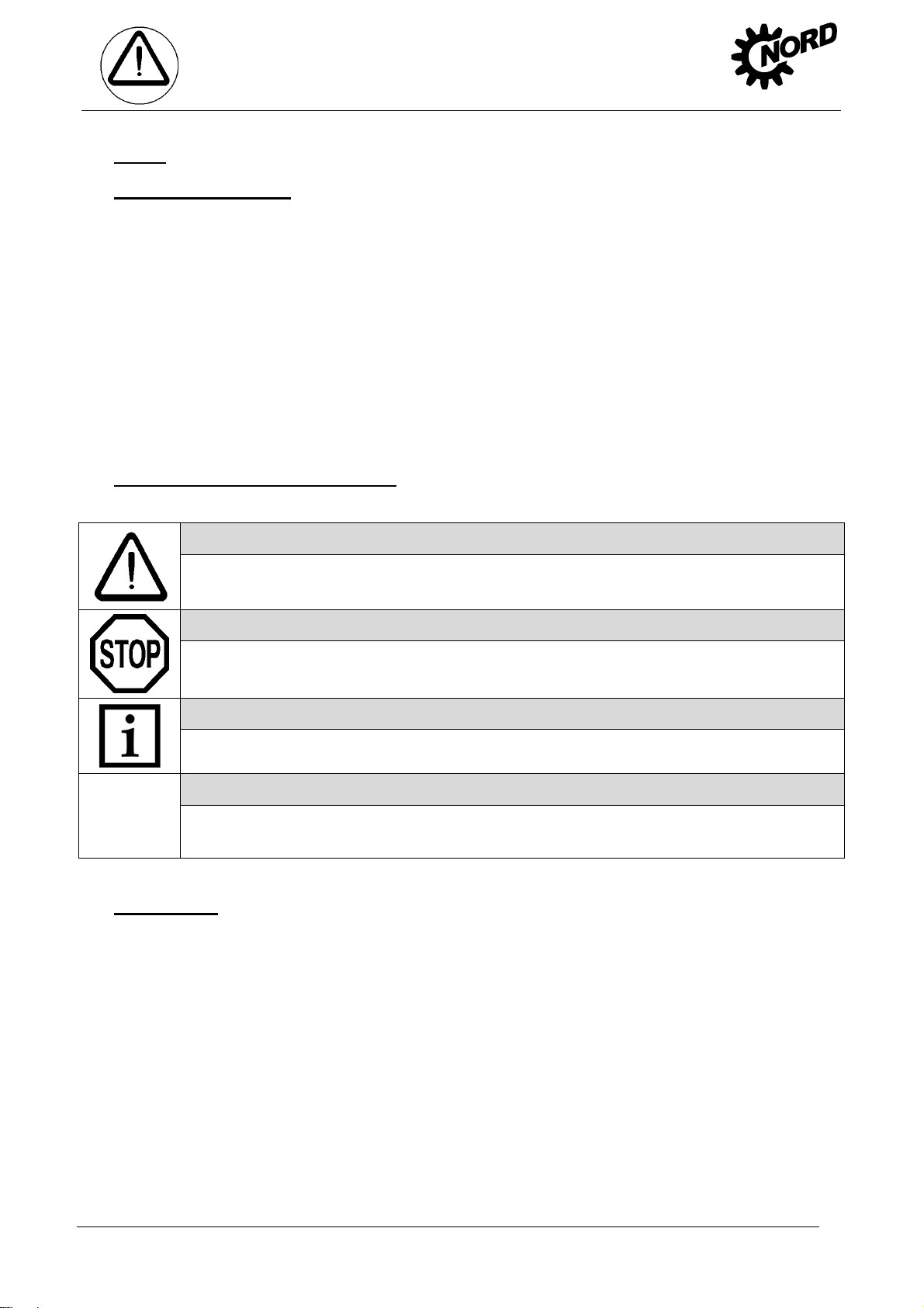
1.2 Safety and information symbols
Please always observe the following safety and information symbols!
Danger!
1. Notes
Risk of fatalities and injury
Attention!
Machine may be damaged
Note!
Useful information
Danger!
Important information about explosion protection
1.3 Correct use
These gear units generate a rotational movement and are intended for use in commercial
systems. They fulfil the explosion protection requirements of Directive 94/9EU (ATEX100a) for
the category stated on the rating plate. No mixture from categories IID and IIG may be present
during operation. The ATEX approval is void in case of a hybrid mixture.
Strict compliance with the technical data on the rating plate is essential. The
documentation must be observed. Appropriate safety measures must be taken for
applications where failure of a gear unit or geared motor may result in injury.
-4- B2000-GB-0413 www.nord.com
Page 5
1.4 Safety information
Danger!
No explosive atmosphere may be present during any work e.g. transportation, storage,
electrical connection, maintenance or repair.
All work including transportation, storage, installation, electrical connection, commissioning,
servicing, maintenance and repair must be performed only by qualified specialist personnel.
It is recommended that repairs to NORD Products are carried out by the NORD Service department.
Danger!
Installation and maintenance work must only be performed when gear units are at a standstill.
The drive must be isolated and secured to prevent accidental start-up.
Tighten the drive elements or secure the parallel key before switching on.
Danger!
1. Notes
Observe all safety information, including that provided in the individual sections of this
Operating Manual. All national and other regulations on safety and accident prevention must
also be observed.
1.5 Disposal
Observe the current local regulations. In particular, lubricants must be collected and disposed of
correctly.
The ringbolts which are screwed to the gear unit must be used for transport. No
additional load may be attached to the gear unit during transport. If geared motors have
an additional eyebolt attached to the motor, this must also be used. Avoid pulling the
eyebolts at an angle. Transportation aids and lifting gear must have an adequate loadbearing capacity.
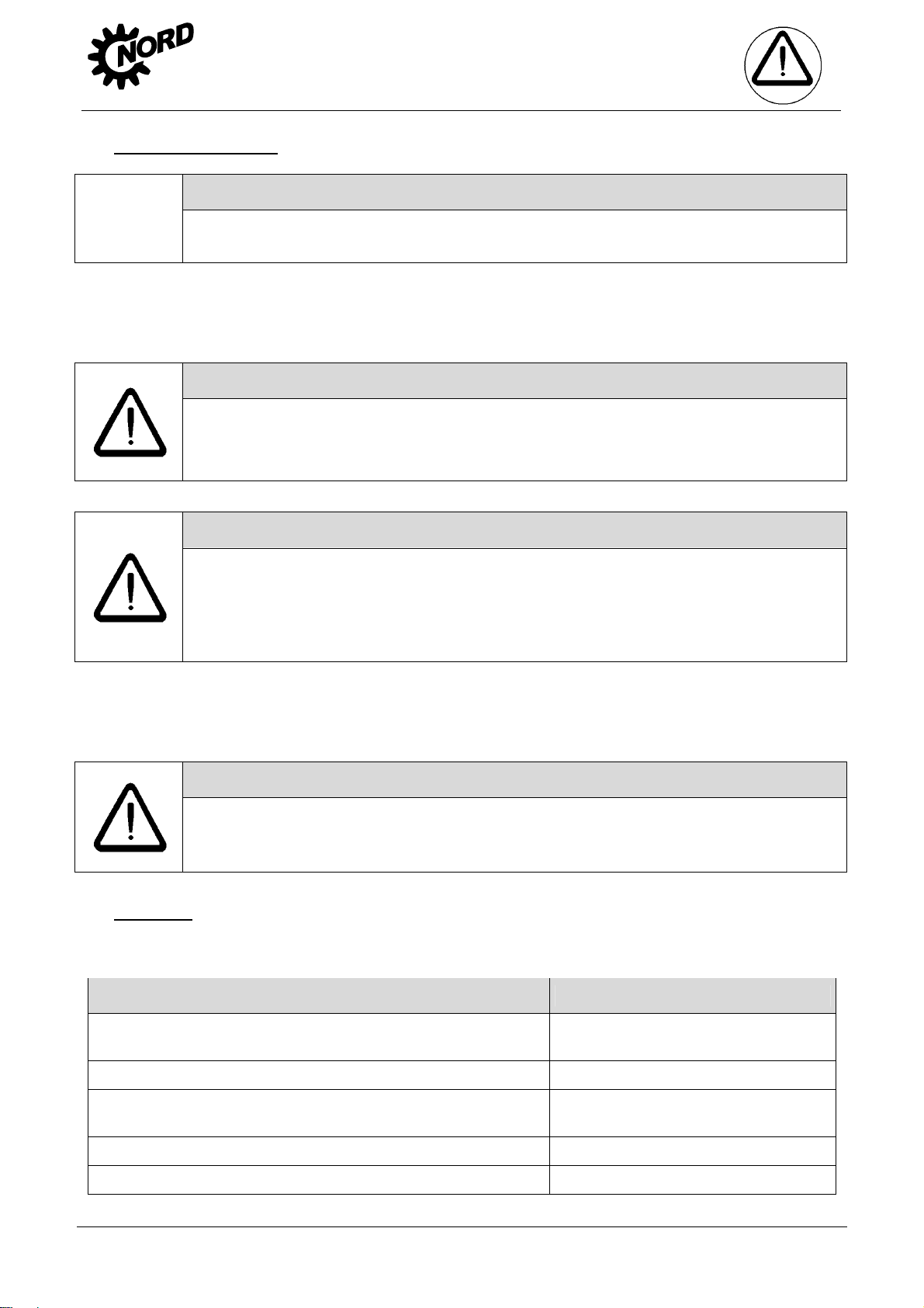
Danger!
Serious physical and property damage may result from inappropriate installation, non-
designated use, incorrect operation, non-compliance with safety information, unauthorised
removal of housing components or safety covers and structural modifications to the gear unit.
Gear unit components: Material:
Toothed wheels, shafts, rolling bearings,
parallel keys, locking rings, …
Gear unit housing, housing components, … Grey cast iron
Light alloy gear unit housing,
light alloy gear unit housing components, …
Worm gears, bushes, ... Bronze
Radial seals, sealing caps, rubber components,… Elastomers with steel
www.nord.com B2000-GB-0413 -5-
Steel
Aluminium
Page 6
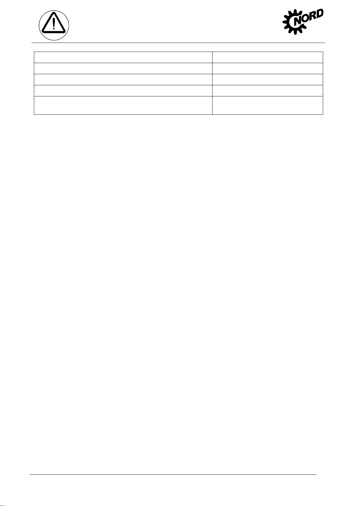
Coupling components Plastic with steel
Flat seals Asbestos-free sealing material
Gear oil Additive mineral oil
Synthetic gear oil (Rating plate labelling: CLP PG) Polyglycol-based lubricants
1. Notes
Cooling spiral, embedding material of the cooling spiral,
screw fittings
Copper, epoxy, yellow brass
-6- B2000-GB-0413 www.nord.com
Page 7
2. Description of gear units
2 Description of gear units
2.1 Type designations and gear unit types
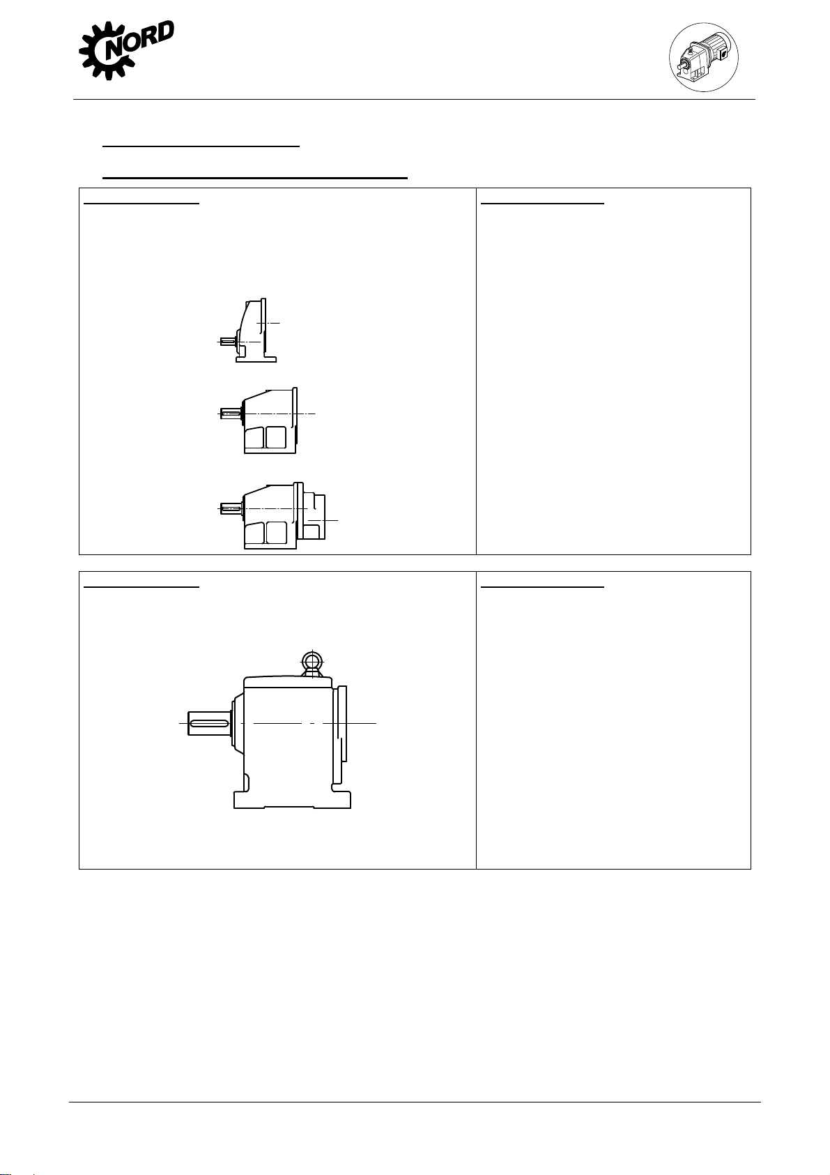
Helical gear units
Type designations:
SK 11E, SK 21E, ..... SK 51E (single-stage)
SK 02, SK 12, ........ SK 52, SK 62N (2-stage)
SK 03, SK 13, SK 23, SK 33N, SK 43, SK 53 (3-stage)
Helical gear units
Type designations:
SK 62, SK 72, SK 82, SK 92, SK 102 (2-stage)
SK 63, SK 73, SK 83, SK 93, SK 103 (3-stage)
Versions / Options
- Foot-mounted version
F Output flange B5
XZ Base and output flange B14
XF Base and output flange B5
VL Reinforced bearings
AL Reinforced axial bearings
IEC Standard IEC motor attachment
NEMA Standard NEMA motor attachment
W With free drive shaft
VI Viton radial seals
OA Oil expansion vessel
SO1 Synthetic oil ISO VG 220
Versions / Options
- Foot-mounted version
F Output flange B5
XZ Base and output flange B14
XF Base and output flange B5
VL Reinforced bearings
IEC Standard IEC motor attachment
NEMA Standard NEMA motor attachment
W With free drive shaft
VI Viton radial seals
OA Oil expansion vessel
SO1 Synthetic oil ISO VG 220
www.nord.com B2000-GB-0413 -7-
Page 8
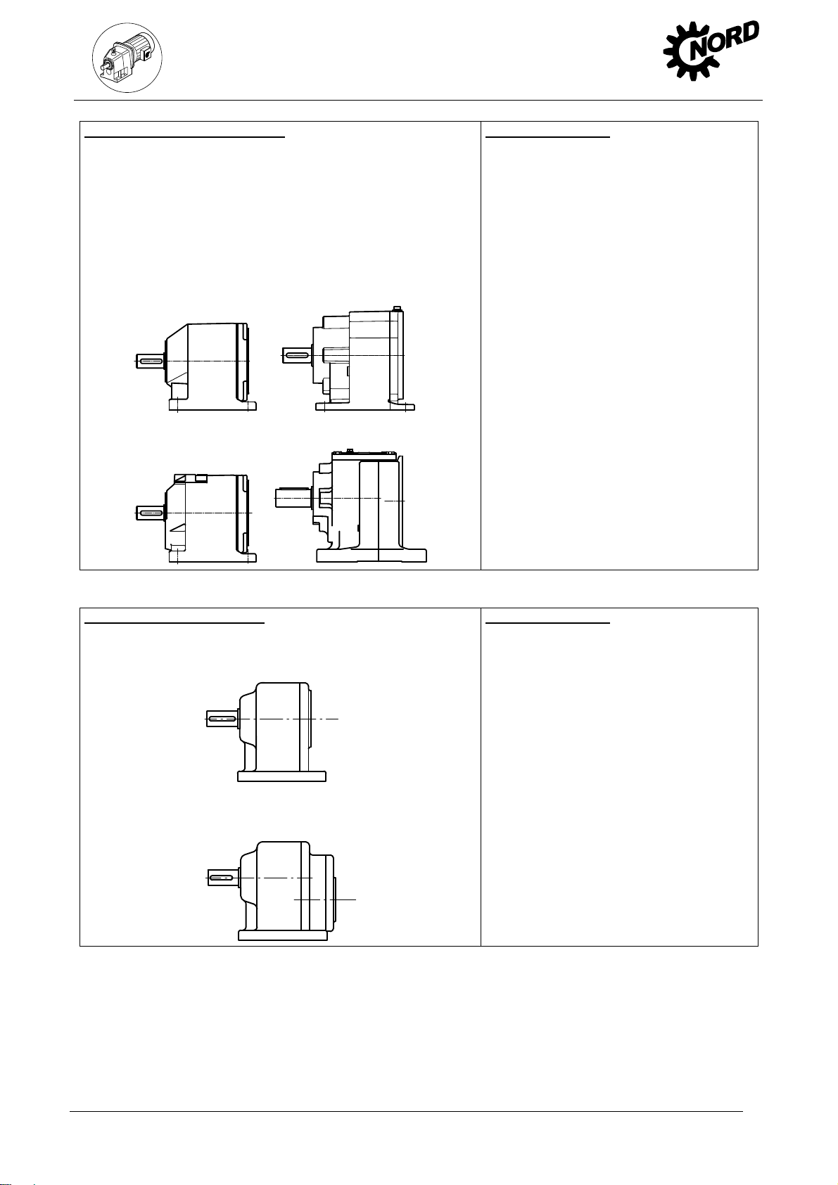
NORDBLOC helical gear units
Type designations:
SK 320, SK 172, SK 272, ..... SK 972 (2-stage)
SK 273, SK 373, ..... SK 973 (3-stage)
SK 072.1, SK 172.1 (2-stage)
SK 372.1, …. SK 672.1 (2-stage)
SK 373.1, …. SK 673.1 (3-stage)
SK 772.1, SK 872.1, SK 972.1 (2-stage)
SK 773.1, SK 873.1, SK 973.1 (3-stage)
2. Description of gear units
Versions / Options
- Foot-mounted version
F Output flange B5
XZ Base and output flange B14
XF Base and output flange B5
VL Reinforced radial bearings
AL Reinforced axial bearings
IEC Standard IEC motor attachment
NEMA Standard NEMA motor attachment
W With free drive shaft
VI Viton radial seals
OA Oil expansion vessel
SO1 Synthetic oil ISO VG 220
Standard helical gear units
Type designations:
SK 0, SK 01, SK 20, SK 25, SK 30, SK 33 (2-stage)
SK 000, SK 010, SK 200, SK 250, SK 300, SK 330 (3-stage)
Versions / Options
- Foot-mounted version
Z Output flange B14
XZ Base and output flange B14
XF Base and output flange B5
F Output flange B5
5 Reinforced output shaft
V Reinforced drive
AL Reinforced axial bearings
IEC Standard IEC motor attachment
NEMA Standard NEMA motor attachment
W With free drive shaft
VI Viton radial seals
SO1 Synthetic oil ISO VG 220
-8- B2000-GB-0413 www.nord.com
Page 9
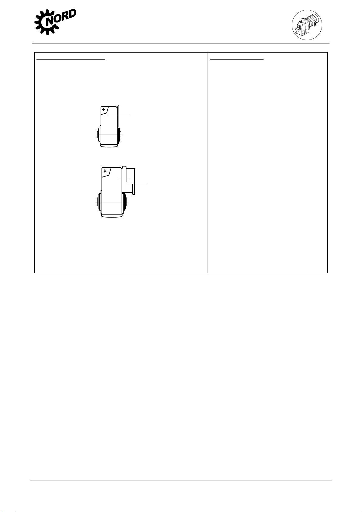
Parallel shaft gear units
Type designations:
SK 0182NB, SK 0282NB, SK 1282, ..... SK 9282, SK 10282, SK
11282
(2-stage)
SK 1382NB, SK 2382, ….. SK 9382, SK 10382, SK 11382, SK 12382
(3-stage)
2. Description of gear units
Versions / Options
A Hollow shaft version
V Solid shaft version
Z Output flange B14
F Output flange B5
X Foot mounting
S Shrink disc
VS Reinforced shrink disc
EA Hollow shaft with internal spline
G Rubber buffer
VG Reinforced rubber buffer
B Fixing element
H Covering cap as contact guard
H66 Covering cap IP66
VL Reinforced bearings
VLII Agitator design
VLIII Drywell agitator de sign
IEC Standard IEC motor attachment
NEMA Standard NEMA motor attachment
W With free drive shaft
VI Viton radial seals
OA Oil expansion vessel
SO1 Synthetic oil ISO VG 220
CC Casing cover with cooling spiral
OT Oil level tank
www.nord.com B2000-GB-0413 -9-
Page 10
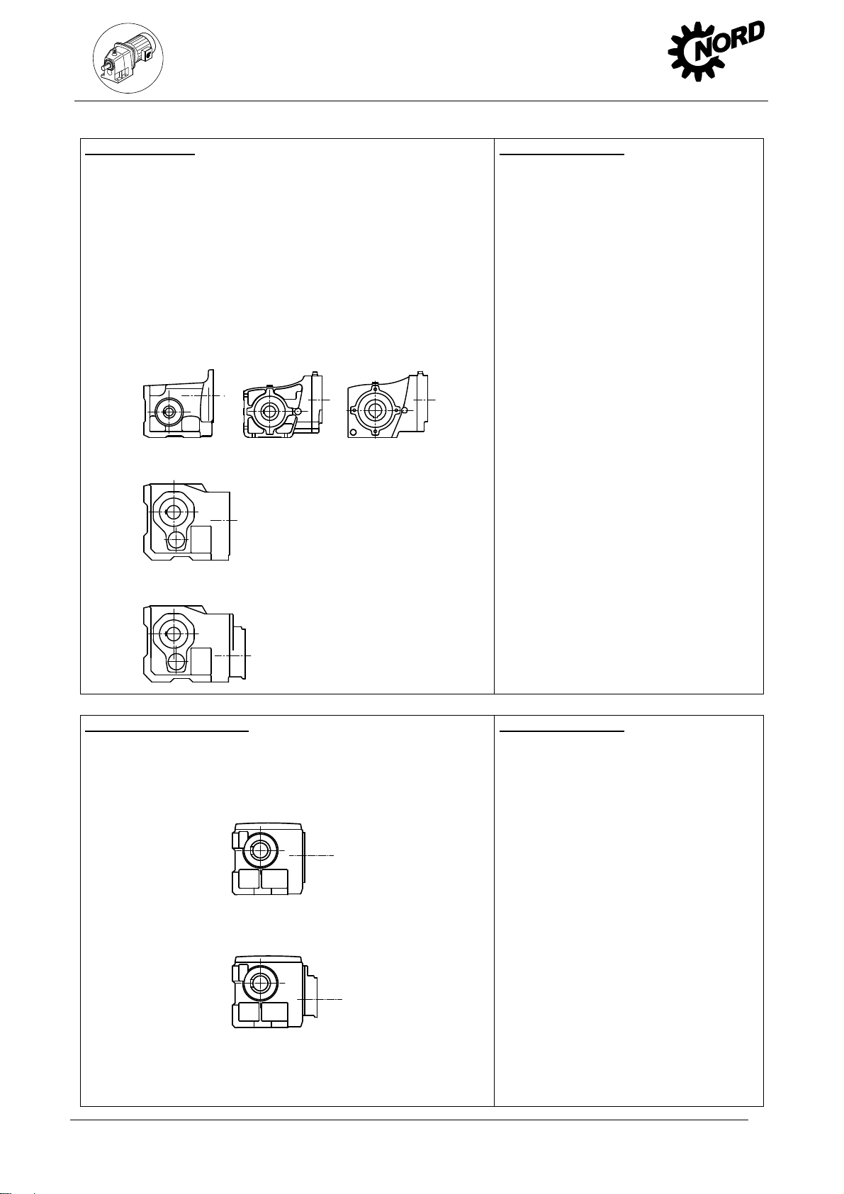
Bevel gear units
Type designations:
SK 92072, SK 92172, SK 92372, SK 92672, SK 92772
SK 92072.1, SK 92172.1, SK 92372.1, SK 92672.1, SK 92772.1,
SK 93072.1, SK 93172.1, SK 93372.1, SK 93672.1, SK 93772.1
(2-stage)
SK 9012.1, SK 9016.1, SK 9022.1, SK 9032.1, SK 9042.1,
SK 9052.1, SK 9062.1, SK 9072.1, SK 9082.1, SK 9086.1,
SK 9092.1, SK 9096.1 (3-stage)
SK 9013.1, SK 9017.1, SK 9023.1, SK 9033.1, SK 9043.1,
SK 9053.1 (4-stage)
Contrate worm gear unit
Type designations:
SK 02040, SK 02050, SK 12063, SK 12080, SK 32100, SK 42125
(2-stage)
SK 13050, SK 13063, SK 13080, SK 33100, SK 43125
(3-stage)
2. Description of gear units
Versions / Options
- Foot mounting with solid shaft
A Hollow shaft version
V Solid shaft version
L Solid shaft both sides
Z Output flange B14
F Output flange B5
X Foot mounting
D Torque support
K Torque console
S Shrink disc
VS Reinforced shrink disc
EA Hollow shaft with internal spline
R Back stop
B Fixing element
H Covering cap as contact guard
H66 Covering cap IP66
VL Reinforced bearings
VLII Agitator design
VLIII Drywell agitator de sign
IEC Standard IEC motor attachment
NEMA Standard NEMA motor attachment
W With free drive shaft
VI Viton radial seals
OA Oil expansion vessel
SO1 Synthetic oil ISO VG 220
CC Casing cover with cooling spiral
Versions / Options
- Foot mounting with solid shaft
A Hollow shaft version
V Solid shaft version
L Solid shaft both sides
X Foot mounting
Z Output flange B14
F Output flange B5
D Torque support
S Shrink disc
B Fixing element
H Covering cap as contact guard
H66 Covering cap IP66
VL Reinforced bearings
IEC Standard IEC motor attachment
NEMA Standard NEMA motor attachment
W With free drive shaft
VI Viton radial seals
OA Oil expansion vessel
-10- B2000-GB-0413 www.nord.com
Page 11
MINIBLOC worm gear units
Type designations:
SK 1S 32, SK 1S 40, SK 1S 50, SK 1S 63, SK 1SU... ,
SK 1SM 31, SK 1SM 40, SK 1SM 50, SK 1SM 63, (1-stage)
SK 2S32NB, SK 2S40NB, SK 2S50NB, SK 2S63NB,
SK 2SU…, SK 2SM40, SK 2SM50, SK 2SM63 (2-stage)
UNIVERSAL worm gear units
Type designations:
SK 1SI31, SK 1SI40, SK 1SI50, SK 1SI63, SK 1SI75,
SK 1SID31, SK 1SID40, SK 1SID50, SK 1SID63, SK 1SID75
SK 1SIS31,…, SK 1SIS75,
SK 1SD31, SK 1SD40, SK 1SD50, SK 1 SD63,
SK 1SIS-D31,…, SK 1SIS-D63
SK 1SMI31, SK 1SMI40, SK 1SMI50, SK 1SMI63, SK 1SMI75
SK 1SMID31,…, SK 1SMID63 (1-stage)
SK 2SD40, SK 2SD50, SK 2SD63, SK 1SI…/31, SK
1SI…/H10,
SK 2SID40,…, SK 2SID63
SK 2SIS-D40,…, SK 2SIS-D63
SK 2SMI40, SK 2SMI50, SK 2SMI63
SK 2SMID40, SK 2SMID50, SK 2SMID 63 (2-stage)
2. Description of gear units
Versions / Options
- Foot mounting with solid shaft
A Hollow shaft version
V Solid shaft version
L Solid shaft both sides
Z Output flange B14
F Output flange B5
D Torque support
X Foot mounting
B Fixing element
IEC Standard IEC motor attachment
NEMA Standard NEMA motor attachment
W With free drive shaft
VI Viton radial seals
Versions / Options
V Solid shaft or plug-in shaft
A Hollow shaft version
L Solid shaft both sides
X Feet on three sides
Z Output flange B14
F Output flange B5
D Torque support
H Covering cap
H10 Modular contrate pre-stage
/31 Worm pre-stage
/40 Worm pre-stage
IEC Standard IEC motor attachment
NEMA Standard NEMA motor attachment
W With free drive shaft
VI Viton radial seals
Double gear units consist of two single gear units. They are to be treated as per the instructions
in this Manual, i.e. as two individual gear units.
Type designation of double gear units: e.g. SK 73/22 (consisting of single gears SK 73 and
SK 22)
www.nord.com B2000-GB-0413 -11-
Page 12
3. Storage, preparation,
installation
3 Storage, preparation, installation
3.1 Storing the gear unit
The following must be observed for storage:
Store in the fitting position (see Section 3.4 and 3.5) and secure gear units against falling
Lightly grease bare metal housing surfaces and shafts
Store in dry rooms
Temperature must not fluctuate beyond the range of –5
Relative humidity less than 60%
No direct exposure to sunlight or UV light
No aggressive, corrosive substances (contaminated air, ozone, gases, solvents, acids,
alkalis, salts, radioactivity etc.) in the immediate vicinity
No vibration or oscillation
3.2 Long-term storage
o
C to +50 oC
Note!
For storage or standstill periods in excess of 9 months, Getriebebau NORD
recommends the long-term storage option. With the long-term storage option and the
use of the measures listed below, storage for up to 2 years is possible. As the actual
influences on the unit greatly depend on the local conditions, these times should only
be regarded as guide values.
Conditions of the gear unit and storage area for long-term storage prior to commissioning:
Store in the fitting position (see Section 3.4 and 3.5) and secure gear units against falling
Transportation damage to the external paint must be repaired. Check that a suitable rust
inhibitor is applied to the flange bearing surfaces. If necessary apply a suitable rust inhibitor
to the surfaces.
Gear units with the long-term storage option are completely filled with lubricant or have VCI
corrosion protection agents added to the gear oil. (See label on gear unit)
The sealing band in the vent plug must not be removed during storage. The gear unit must
remain sealed tight.
Store in a dry place.
In tropical regions, the drive unit must be protected against damage by insects
Temperature must not fluctuate beyond the range of –5
o
C to +40 oC
Relative humidity less than 60%
No direct exposure to sunlight or UV light
No aggressive, corrosive substances (contaminated air, ozone, gases, solvents, acids,
alkalis, salts, radioactivity etc.) in the immediate vicinity
No vibration or oscillation
Measures during storage or standstill periods
If the relative humidity is <50% the gear unit can be stored for up to 3 years.
-12- B2000-GB-0413 www.nord.com
Page 13
3. Storage, preparation,
Measures before commissioning
If the storage or standstill period exceeds 2 years or the temperature during short-term
storage greatly deviates from the standard range, the lubricant in the gear unit must be
replaced before commissioning (See Section 5.2).
If the gear unit is completely filled, the oil level must be reduced before commissioning (See
Section 3.5 and 6.1).
3.3 Inspecting the drive unit
Danger!
The drive unit must be inspected and may only be installed if:
No damage, e.g. due to storage or transport is apparent. In particular the shaft
sealing rings, the sealing caps and the covers must be inspected for damage.
No leakage or no oil loss is visible.
No corrosion or other indications of incorrect or damp storage is apparent.
The packaging material has been completely removed.
installation
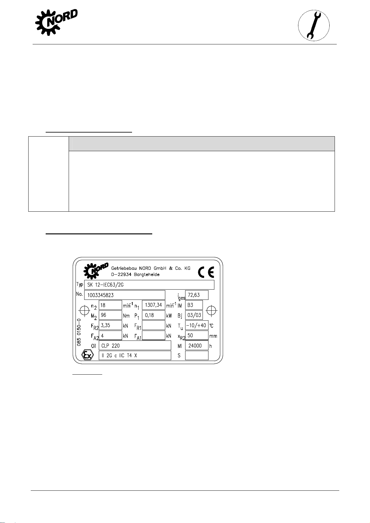
3.4 Checking the rating plate data
The rating plate must be firmly attached to the gear unit and must not be subjected to permanent
soiling. Please contact the NORD service department if the rating plate is illegible or damaged.
Figure 3-1: Rating plate (example)
www.nord.com B2000-GB-0413 -13-
Page 14
3. Storage, preparation,
g
1
1
A
A
Explanation of the Rating Plate
Abbreviation Unit Designation See
Typ - NORD gear unit type
No. - Serial number
i
- Overall gear unit ratio
es
n2 min
n1 min
IM - Configuration (installation orientation) Section 6.1
M2 Nm Max. permissible gear unit drive shaft torque
P1 kW Max. permissible drive power or motor power
Bj - Year of manufacture
FR2 kN Max. permissible transverse force on the gear unit driven shaft Section 3.8
FR1 kN Max. permissible transverse force on the gear unit drive shaft for option W Section 3.8
Tu °C Permissible ambient temperature for the gear unit
-
Rated speed of gear unit drive shaft*
-
Rated speed of the gear unit drive shaft or the drive motor*
installation
F
kN Max. permissible axial force on the gear unit driven shaft Section 3.8
2
F
kN Max. permissible axial force on the gear unit drive shaft for option W Section 3.8
1
MI h Interval between general overhauls of the gear unit in operating hours
or details of the non-dimensional maintenance class CM
xR2 mm Max. dimension for the point of application of the transverse force FR2 Section 3.8
Oil - Gear unit oil type (standard designation) Section 6.2
Last line
S - Number of the special documentation, consisting of serial no. / year
*The maximum permissible speeds are 10% above the rated speed, if the maximum permissible drive power
P1 is not exceeded.
If the fields FR1, FR2, FA1 und FA2 are empty, the forces are zero. If the field xR2 is empty, the point of
application of force F
-
Labelling as per ATEX (DIN EN 13463-1):
1. Group (always II, not for mines)
2. Category (2G, 3G for gas or 2D, 3D for dust)
3. Ignition protection type if fitted (c)
4. Explosion group if applicable (IIC, IIB)
5. Temperature class (T1-T3 or T4 for gas) or max. surface
temperature e.g. 125°C for dust)
6. Temperature measurement on commissioning (X)
is central on the drive shaft journal (See Figure 3-4).
R2
Section 5.2
Section 5.2
Section 4.3
Danger!
It must be checked and ensured that the gear unit type, all technical data and the ATEX
labelling conform to the planning of the plant or the machine.
It should be noted that with geared motors, the electric motor has its own rating plate with a
separate ATEX labelling. The motor labelling must also comply with data for the planning of the
plant or the machine. The lowest explosion protection of the gear unit and the motor
-14- B2000-GB-0413 www.nord.com
Page 15
3. Storage, preparation,
labelling applies for the geared motor unit. If the electric motor is driven with a frequency
inverter, the motor requires ATEX approval for inverter operation.
3.5 Checking the configuration
Danger!
The gear unit may only be operated in the stated configuration. The permissible
configuration is stated on the rating plate (IM ….). If an X is present in the field IM, the
special documentation, whose number is in field S, must be observed. Section 6.1, or
the special documentation, shows the configuration of the individual types of gear
units. It must be checked and ensured that the configuration as stated on the rating
plate complies with the installation orientation and that the installation orientation does
not change during operation.
The UNIVERSAL worm gear units type SK1SI... do not depend on the version, as with
these types of gear unit, the abbreviation UN is entered in the IM field of the type plate.
3.6 Preparing for installation
The drive unit must be inspected and may only be installed if no transportation damage or leaks
are visible. In particular the radial seals and the sealing caps must be inspected for damage.
All bare metal surfaces and shafts of the gear unit are protected against corrosion with oil,
grease or corrosion protection agents before shipping.
Thoroughly remove all oil, grease or corrosion protection agents and any dirt from the shafts and
flange surfaces before assembly.
installation
Danger!
Care must be taken that drive elements attached to the gear unit, such as clutches,
pulleys etc. and drive motors are also ATEX-compliant.
In applications where an incorrect rotational direction may result in damage or potential risk, the
correct rotational direction of the drive shaft is to be established by test running the drive when
uncoupled and guaranteeing such for subsequent operation.
Danger!
Gears with integrated return stops are marked with arrows on the driven/driving sides.
The arrows point in the rotation direction of the gear unit. It must be ensured, when
connecting the motor and during motor control, that the gear unit can only operate in
the rotation direction, e.g. by means of a rotary field test. Switching of the motor into
the blocked direction of rotation, i.e. the wrong direction of rotation may cause damage
to the gear unit.
Ensure that no aggressive or corrosive substances are present in the area surrounding the
installation site or are subsequently expected during operation, which attack metal, lubricants or
elastomers. In case of doubt, please contact Getriebebau NORD and take the recommended
action.
www.nord.com B2000-GB-0413 -15-
Page 16
3. Storage, preparation,
Oil expansion tanks (Option OA) must be fitted in accordance with works standard WN 0-530 04.
For M10x1 screw fixings, the attached works standard WN 0-521 35 must also be observed.
The pressure vent must be activated prior to commissioning. To activate, remove the transport
securing devices.
Double gear units consist of two single units and are equipped with 2 oil chambers and 2
pressure vents. Position of the vent plug: see Section 6.1.
Figure 3-2: Activation of the pressure vent
3.7 Installing the gear unit
installation
Danger!
The eyebolts screwed into the gear units must be used during installation. During
installation, no additional weights may be attached to the gear unit. If geared motors
have an additional eyebolt attached to the motor, this must also be used. Avoid pulling
the eyebolts at an angle.
Danger!
No explosive atmosphere must be present when installing the gear unit.
The base and/or flange to which the gear unit is fitted should be vibration-free, torsionally rigid
and flat (flatness error <0.2 mm). All contamination to the bolting surfaces of gear unit and base
and/or flange must be thoroughly removed.
The gear unit housing must always be earthed. With geared motors, earthing via the motor
connection must be ensured.
The gear unit must be installed in the correct configuration (See Section 3.5 and 6.1). All
gear unit feet and/or all flange bolts on each side must be used. Bolts must have a minimum
quality of 10.9. The bolts must be tightened to the correct torques (refer to Section 6.3 for torque
values). Tension-free bolting must be ensured, particularly for gear units with a foot and flange.
The oil inspection screws, oil drain screws and the vent valves must be accessible.
To ensure that the gearbox does not get too warm and to avoid injury to persons, observe
the following during installation:
Danger!
The surfaces of gear units or geared motors may become hot during or shortly after operation.
Attention: danger of burns! Protection against accidental contact may need to be installed.
-16- B2000-GB-0413 www.nord.com
Page 17
3. Storage, preparation,
installation
Danger!
The cooling air supplied to the gear unit/geared motor must be within the permissible
temperature range stated on the rating plate.
In case of direct sunlight falling onto the gear unit, the cooling air supplied to the gear
unit/geared motor must be at least 10°C below the highest permissible temperature of
the ambient temperature range Tu, which is stated on the rating plate.
Enable the free flow of air to all sides of the gear unit.
Ensure adequate space around the gear unit.
With geared motors, the cooling air of the motor fan must be able to flow unobstructed
onto the gear unit.
Do not enclose or encase the gear unit/geared motor.
Do not subject the gear unit to highly energetic radiation.
Do not direct warm exhaust air from other units onto the gear unit/geared motor.
The base or flange to which the gear unit is attached must not input any heat into the
gear unit during operation.
Do not pile up dust in the area of the gear unit
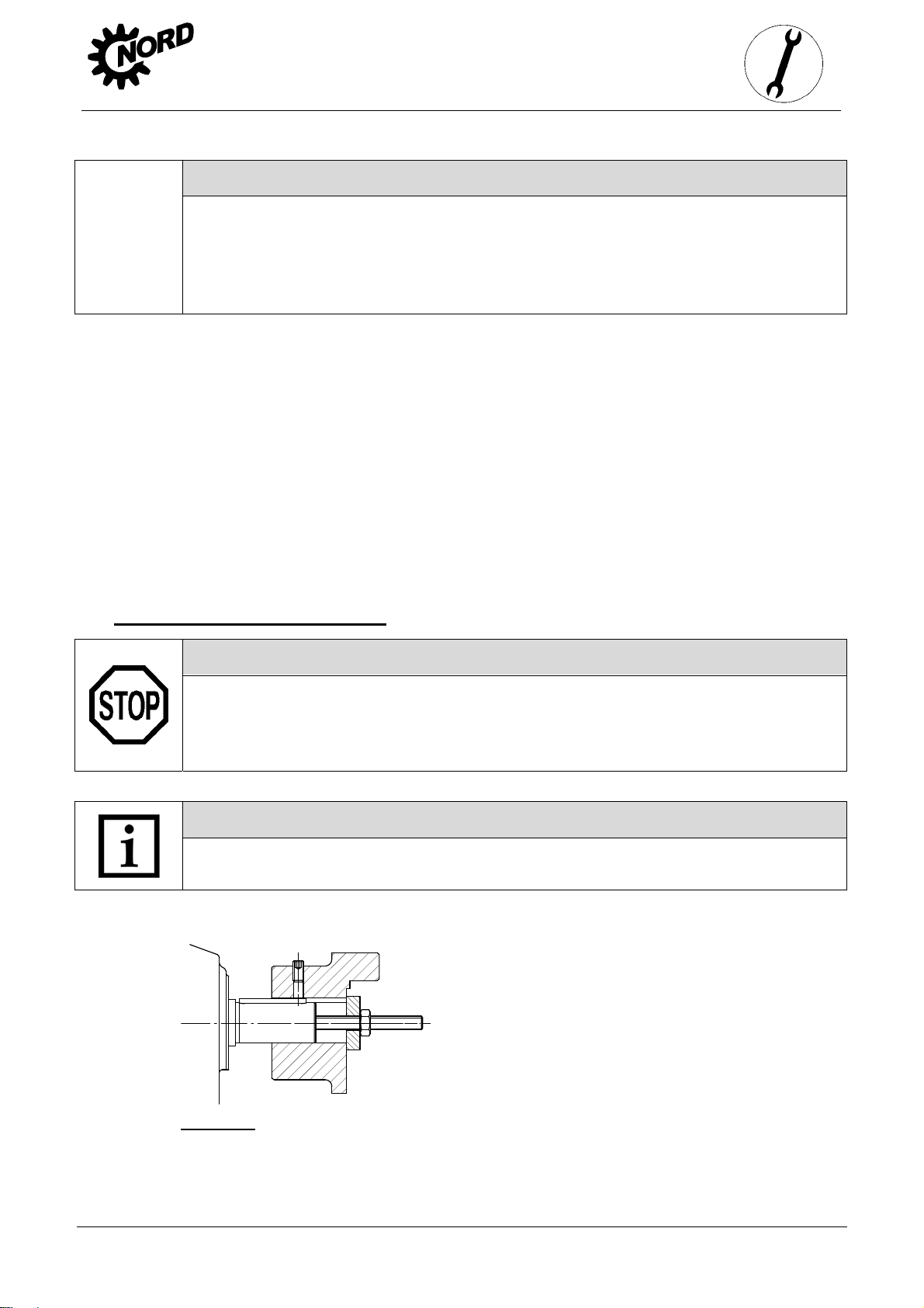
3.8 Fitting hubs on the gear shafts
Danger!
Drive and driven elements, e.g. coupling and chain-wheel hubs must be mounted onto
the drive and driven shaft of the gear unit using suitable pullers that will not apply
damaging axial forces onto the gear unit. In particular, do not hit the hubs with a
hammer.
Note!
Use the end thread of the shafts for pulling. Fitting can be aided by coating the hub
with lubricant or heating it up to approx. 100
o
C beforehand.
Figure 3-3: Example of a simple pulling device
www.nord.com B2000-GB-0413 -17-
Page 18
3. Storage, preparation,
installation
Danger!
Drive and driven elements, such as belt drives, chain drives and couplings must be
fitted with contact protection.
Danger!
Care must be taken that drive and driven elements attached to the gear unit must also
be ATEX-compliant.
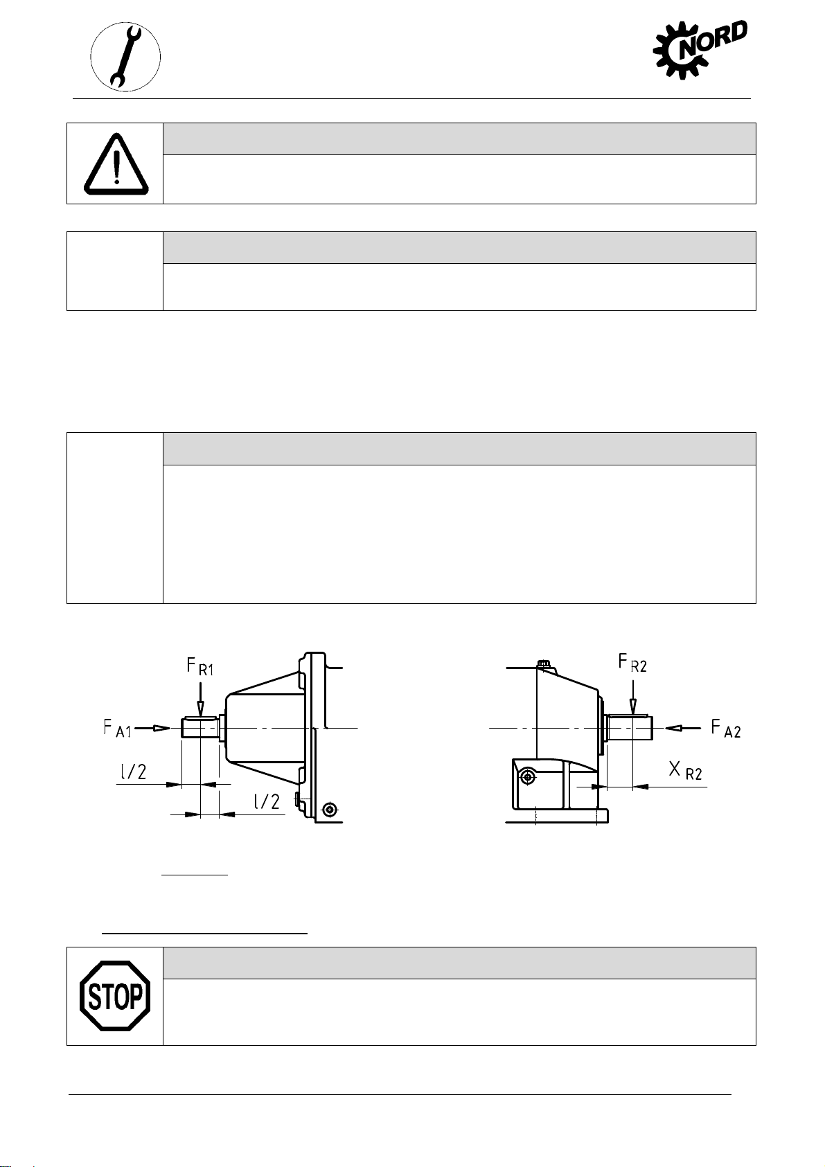
Drive and driven elements may only subject the drive units to the maximum radial forces
and FR and axial forces FA1 and FA as specified on the rating plate (See Section 3.4).
F
R1
Observe the correct tension, particularly on belts and chains. Additional loads due to unbalanced
hubs are not permitted.
Danger!
The radial force must be applied to the gear unit as closely as possible. For drive
shafts with free shaft ends – Option W – the maximum permissible transverse force
FR1 applies for the application of the transverse force to the centre of the free shaft
journal. For driven shafts, the application of the transverse force FR2 must not exceed
the dimension xR2 . If the transverse force F
rating plate, but no dimension xR2 is stated, the application of the force is assumed to
be to the centre of the shaft journal.
for the driven shaft is stated on the
R2
Free drive shaft (Option W) Driven shaft
Figure 3-4: Permissible application of force to drive and driven shafts
3.9 Fitting push-on gear units
Attention!
The push-on gear unit must be fitted onto the shaft using a suitable puller, which will
not exert damaging axial forces on the gear unit. In particular, do not hit the gear unit
with a hammer.
-18- B2000-GB-0413 www.nord.com
Page 19

3. Storage, preparation,
Assembly and subsequent dismantling is facilitated by applying an anti-corrosive lubricant to the
shaft before fitting (e.g. Nord Anti-Corrosion Art.-No. 089 00099). Excess grease or anticorrosion agent may escape after assembly and bay drip off. Clean these points on the output
shaft after a running-in time of approx. 24 hours. This escape of grease is not due to a leak in
the gear unit.
Figure 3-5: Applying lubricant to the shaft and the hub
installation
Note!
The gear unit can be fitted to shafts with and without a shoulder using the fastening
element (Option B). Tighten the bolt of the fastening element to the correct torque. (See
Chapter 6.3 for torque values.) For gear units with option H66, the factory-fitted closing
cap must be removed before fitting.
For shaft mounted gear units with option H66 and fastening element (Option B) the pressed-in
closing cap must be pushed out before fitting the gear unit. The pressed-in closing cap may be
destroyed during dismantling. As standard a second closing cap is supplied as a loose spare
part. After fitting the gear unit, fit the new / new condition closing cap as described in Section 3.11.
Figure 3-6: Removing the factory-fitted closing cap
Figure 3-7: Gear unit mounted to shaft with a shoulder using the fastening element
www.nord.com B2000-GB-0413 -19-
Page 20

3. Storage, preparation,
Figure 3-8: Gear unit mounted to shaft without a shoulder using the fastening element
A gear unit can be dismantled from a shaft with shoulder using the following device, for example.
Figure 3-9: Dismantling using dismantling device
installation
When mounting push-on gears with torque supports, the support must not be distorted. Tensionfree mounting is aided by the rubber buffer (Option G and/or VG).
Figure 3-10: Mounting the rubber buffer (Option G and/or VG) on parallel shaft gear units
To fit the rubber buffer, tighten the screw fastening until there is no play between the contact
surfaces when there is no load. Then turn the fastening nut (only applies for adjusting threads)
half a turn in order to pre-tension the rubber buffer. Greater pre-tension is not permissible.
Secure the screw fastening against coming loose, e.g. with Loctite 242 or a second nut.
-20- B2000-GB-0413 www.nord.com
Page 21

3. Storage, preparation,
Figure 3-11: Attaching the torque support on bevel gear and worm gear units
Tighten the bolts on the torque support to the correct torque (see Section 6.3 for tightening
torque values) and secure to prevent loosening. (e.g. Loctite 242, Loxeal 54-03)
installation
Always support torque support on both sides!
3.10 Fitting shrink discs
Shrink disc type, Mat. No.
and torque details for tensioning screws
Tensioning screws DIN 931 (933) -10.9
The shrink discs are supplied by the manufacturer
ready for fitting. They must not be dismantled prior to
fitting.
Figure 3-12: Hollow shaft with shrink disc
Attention!
Tensioning flanges
Solid shaft of machine
Hollow shaft of gear unit
Double half-slotted inner ring
Shaft and hollow shaft bore
GREASE FREE!
Do not tighten the tensioning screws if the shaft is not inserted!
Assembly sequence:
1. Remove any transport securing devices.
2. Loosen but do not remove tightening bolt and tighten gently by hand until there is no play
between the flanges and the inner ring.
www.nord.com B2000-GB-0413 -21-
Page 22

3. Storage, preparation,
3. Slide the shrink disc onto the hollow shaft until the outer clamping flange is flush with the
hollow shaft. The shrink disc is easier to slide on if the bore of the inner ring is lightly
greased.
4. Prior to mounting, grease the solid shaft only in the area which will later come into contact
with the bronze bush in the hollow shaft of the gear unit. Do not grease the bronze bush, in
order to prevent grease penetrating the area around the shrink connection.
5. The hollow shaft of the gear unit must be completely de-greased and completely
free of grease.
6. In the area of the shrink connection the solid shaft of the machine must be degreased and
completely free of grease.
7. Insert the solid shaft of the machine into the hollow shaft so as to completely fill the area
around the shrink connection.
8. Position the clamping flange by gently tightening the bolts.
9. Tighten the bolts successively in a clockwise direction by several turns – not crosswise –
with approx. ¼ rotation per turn. Tighten the bolts with a torque wrench to the torque
indicated on the shrink disc.
10. When the tensioning bolts have been tightened, there must be an even gap between the
clamping flanges. If this is not the case, the gear unit must be dismantled and the shrink disc
connection checked for correct fit.
11. The hollow shaft of the gear unit and the solid shaft of the machine should be marked with a
line (felt-tip pen) in order to detect any slippage under load.
installation
Danger!
Risk of injury from incorrect mounting and dismantling.
Dismantling sequence:
1. Loosen the bolts successively in a clockwise direction by several turns with approx. ¼
rotation per turn. Do not remove the bolts from their thread.
2. Loosen the clamping flanges from the cone of the inner ring.
3. Remove the gear unit from the solid shaft of the machine.
If a shrink disk has been in use for a long period or is dirty, it must be dismantled, cleaned and
the conical surfaces coated with Molykote G Rapid Plus or a similar lubricant before it is refitted.
The treads and head surfaces of the screws must be treated with grease without Molykote. In
case of damage or corrosion, damaged components must be replaced.
3.11 Fitting the covers
Danger!
Shrink disks require protection against contact. Covers (Option H) serve as contact
protection. These must always be used if contact protection is not provided by other
methods.
-22- B2000-GB-0413 www.nord.com
Page 23

3. Storage, preparation,
installation
Danger!
Covers must be inspected for transportation damage e.g. dents and warping before
they are fitted. Damaged covers must not be used, as they may cause rubbing.
All fixing screws must be used and coated prior to use with a securing lubricant e.g. Loctite 242,
Loxeal 54-03 and tightened to the correct torque. (See Section 6.3 for torque values) For covers
with option H66, press in the new / new condition closing cap by tapping it lightly with a hammer.
Figure 3-13: Fitting the covers, Option SH, Option H, and Option H66
3.12 Fitting a standard motor
Danger!
Only standard motors with an adequate ATEX Zone category according to the rating
plate may be used. In addition, for ATEX category 2D gear units (see the ATEX labelling
on the last line of the gear unit rating plate), the motor must have at least protection
class IP6x.
The maximum permitted motor weights indicated in the table below must not be exceeded:
Maximum permitted motor weights
IEC motor size 63 71 80 90 100 112 132 160 180 200 225 250 280 315
NEMA Motor size 56C 143T 145T 182T 184T 210T 250T 280T 324T 326T 365T
Max. motor weight [kg] 25 30 40 50 60 80 100 200 250 350 500 700 1000 1500
Assembly procedure to attach a standard motor to the IEC adapter (Option IEC)/NEMA adapter
1. Clean motor shaft and flange surfaces of motor and adapter and check for damage.
Mounting dimensions and tolerances of the motor must conform to DIN EN 50347/NEMA
MG1 Part 4.
2. Push the coupling sleeve onto the motor shaft so that the motor parallel key engages into
the groove in the sleeve on tightening.
3. Tighten the coupling sleeve on the motor shaft in accordance with the motor manufacturer’s
instructions until it touches the collar. With motor sizes 90, 160, 180 and 225, any spacer
bushes must be positioned between the coupling sleeve and the collar. With standard helical
gear units, dimension B between the coupling sleeve and the collar must be observed (see
Figure 3-14). Certain NEMA adapters require the adjustment of the coupling in accordance
with the specifications indicated on the adhesive plate.
www.nord.com B2000-GB-0413 -23-
Page 24

3. Storage, preparation,
installation
4. If the coupling half contains a threaded pin, the coupling must be secured axially on the
shaft. The threaded pin must be coated prior to use with a securing lubricant e.g. Loctite
242, Loxeal 54-03 and tightened to the correct torque. (See Chapter 6.3 for torque values)
5. The flange surfaces of motor and adapter must be completely coated with surface sealant
e.g. Loctite 574 or Loxeal 58-14 prior to mounting the motor, so that the flange seals after
mounting. (only necessary for category 2D gear units – see ATEX labelling on the last line of
the gear unit rating plate) Sealing of the flange surfaces is also recommended for installation
outdoors or in damp environments.
6. Mount the motor to the adapter. Do not forget to fit the gear rim or the sleeve.
(See Figure 3-14)
7. Tighten the adapter bolts to the correct torque. (See Chapter 6.3 for torque values)
Figure 3-14: Fitting the coupling onto the motor shaft - various types of coupling
I Gear coupling (BoWex), one-part
II Gear coupling (BoWex
III Gear coupling (BoWex
IV Claw coupling (ROTEX
V Claw coupling (ROTEX
), two-part
), two-part with spacer bush
), two-part
), two-part, observe dimension B:
Standard helical gear unit: SK0, SK01, SK20, SK25, SK30, SK33 (2-stage)
SK010, SK200, SK250, SK300, SK330 (3-stage)
IEC size 63 IEC size 71
Dimension B (Figure 3-12 V) B = 4.5mm B = 11.5 mm
VI Claw coupling (ROTEX), two-part with spacer bush
-24- B2000-GB-0413 www.nord.com
Page 25

3. Storage, preparation,
3.13 Subsequent paintwork
Attention!
For retrospective painting of the gear unit, the radial seals, rubber elements, pressure venting
valves, hoses, type plates, adhesive labels and motor coupling components must not come
into contact with paints, lacquers or solvents, as otherwise components may be damaged or
made illegible.
3.14 Temperature sticker
Danger!
With temperature class T4 gear units with a maximum surface temperature of less than
135°C the supplied self-adhesive temperature sticker (printed with value 121°C) must
be affixed to the gear unit housing. (Part No.:283 9050).
The temperature class or the maximum surface temperature can be seen from the ATEX
labelling in the last line of the rating plate.
Examples: II 2G c IIC T4 X or II 3D 125°C X
The temperature sticker must be affixed next to the oil level screw (See Section 6.1) towards the
motor. For gear units with an oil level vessel, the temperature sticker must be affixed in the same
position as for gear units without an oil level vessel. For gear units which are lubricated for life,
without oil maintenance, the temperature sticker should be affixed next to the rating plate.
installation
Figure 3-15: Position of the temperature sticker
3.15 Fitting the cooling coil to the cooling system
The cooling coil is recessed into the housing cover (See Item 2, Figure 3-16). Cutting ring screw
threads (see Item 1, Figs. 3-16) are located at the casing cover for the connection of a pipe with
an external diameter of 10 mm according to DIN 2353. Remove the drain plug from the screw
neck prior to assembly to avoid any contamination of the cooling system. The screw necks
should be connected with the coolant circuit, which must be provided by the operator. The flow
direction of the coolant is irrelevant.
www.nord.com B2000-GB-0413 -25-
Page 26

3. Storage, preparation,
Make sure not to twist the screw necks during or after assembly as the cooling coil may be
damaged (see Item 3, Figure 3-16). You must ensure that no external forces act on the cooling
coil.
1
2
Figure 3-16: Cooling cover
installation
3
Danger!
The pressure released from the cooling circuit before carrying out any work on the gear
unit.
-26- B2000-GB-0413 www.nord.com
Page 27

4 Commissioning
4.1 Check the oil level
Danger!
Before commissioning, the oil level must be checked with the supplied dipstick.
The installation must comply with the configuration on the rating plate. Section 6.1 describes the
versions and the corresponding oil level screws. With double gear units, the oil level must be
checked on both units. The pressure vent must be at the position marked in Section 6.1.
The oil level does not need to be checked on gear units without oil level screw (see Section 6.1).
Gear unit types that are not supplied full of oil must be filled before the oil level is checked.
(See Section 5.2)
Checking the oil level:
1. The oil level must only be checked when the gear unit is at a standstill and has cooled
down. The gear unit must be secured to prevent accidental switch-on.
2. Gear units with oil level screw:
4. Commissioning
Standard configuration M4 (V1 and V5) helical gear units have an angled pipe for checking
the oil level. This must point vertically upwards as shown in Figure 4-1 C. Before checking the
oil level, the pressure vent must be unscrewed.
The oil level screw corresponding to the version must be screwed out. (See Section 6.1)
The oil level in the gear unit should be checked with the supplied dipstick
(Part No.: 283 0050) as shown in Figure 4-1 A, C. To do this, the part of the dipstick which is
submerged in the oil must be held vertically.
The maximum oil level is the lower edge of the oil level hole.
The minimum oil level is approx. 4 mm below the lower edge of the oil level hole. The dipstick
then just dips into the oil.
If the oil level is not correct, it must be adjusted by draining off oil or topping up with the type
of oil stated on the rating plate.
If the screw lock coating in the thread of the oil drain screw or oil level screw is damaged, a
new oil level screw must be used or the thread cleaned and coated with securing adhesive,
e.g. Loctite 242, Loxeal 54-03 prior to insertion.
Check the sealing ring for damage. Replace with a new sealing ring in case of damage.
Fit the oil level screw together with the sealing ring and tighten to the correct torque. (See
Section 6.3 for torque values)
If the pressure vent has been unscrewed, reinsert it together with the sealing ring and tighten
to the correct torque. (See Section 6.3 for torque values)
3. Gear units with an oil level vessel:
The oil level must be checked in the oil level vessel with the aid of the dipstick plug (thread
G1 1/4). The oil level must be between the upper and lower marking when the dipstick is fully
screwed in (see Figure 4-1 B). These gearboxes may only be operated in the configuration
stated in Section 6.1.
www.nord.com B2000-GB-0413 -27-
Page 28

A
4. Gear units with oil inspection glass:
Check the oil level as described under 2. The oil level must be checked by means of its position
in the oil inspection glass.
5. Final check: Previously loosened screws must be correctly tightened.
4. Commissioning
Figure 4-1: Check the oil level with a dipstick
B
4.2 Activating the Automatic Lubricant Dispenser
Danger!
Some gear unit types with standard motor (Option IEC/NEMA) have an automatic
lubricant dispenser for the rolling bearings. This dispenser must be activated prior to
commissioning. The cartridge case cover has a red information sign for the activation
of the lubricant dispenser.
Activating the Automatic Lubricant Dispenser:
1. Loosen and remove cylinder bolts M8x16 (1)
2. Lift off cartridge case cover (2)
3. Insert activation screw (3) into the lubricant dispenser (5) until the lug (4) breaks off at the
defined fracture point
4. The flange surfaces of the cartridge case cover (2) must be completely coated with
surface sealant e.g. Loctite 574 or Loxeal 58-14 prior to assembly, so that the cover seals
after it has been fitted. (Only necessary for Category 2D gear units – see ATEX labelling,
last line of the rating plate)
5. Refit cartridge case cover (2) and fasten using cylinder bolt (1). (See Chapter 6.3 fo r torque
values)
6. Mark activation date on the adhesive plate (6) indicating month/year
C
-28- B2000-GB-0413 www.nord.com
Page 29

Attention!
Screw in the activation screw until the lug breaks off
before commissioning the gear unit.
Dispensing time: 12 Months
Month Activation date Year
1 2 3 4 5 6 7 8 9 10 11 12 99 00 01 02 03
Figure 4-2: Activating the automatic lubricant dispenser with standard motor mounting
4.3 Temperature measurement
The details of the ATEX temperature class or the maximum surface temperature are based on
normal installation conditions (See Section 3.6). Even small changes to the installation
conditions can have a significant effect on the temperature of the gear unit.
4. Commissioning
Danger!
On commissioning, a surface temperature measurement of the gear unit must be made
under maximum load.
(This does not apply to gear units which are labelled as temperature class T1 – T3 or a
maximum surface temperature of 200°C in the last line of the rating plate.)
For the measurement, a normal temperature measuring device is required, with a measurement
range from 0°C to 130°C and a precision of at least ± 4°C and which enables the measurement
of the surface temperature and the temperature of the air. Temperature measurement
procedure:
1. Allow the gear unit to run at maximum speed under maximum load for approx. 4 hours.
2. After it has warmed up, measure the temperature of the surface of the gear unit housing
Tgm immediately next to the temperature label (See Section 3.14).
3. Measure the temperature of the air Tum in the immediate vicinity of the gear unit.
Danger!
The gear unit must be shut down and Getriebebau NORD must be consulted if any of
the following criteria do not apply:
The measured air temperature Tum is within the permissible range stated on the rating plate.
The measured temperature of the surface of the gear unit housing Tgm is below 121°C and
the temperature sticker has not turned black. (See Figure 4-3)
www.nord.com B2000-GB-0413 -29-
Page 30

g
g
The measured temperature of the surface of the gear unit housing plus the difference
between the highest permissible air temperature Tu stated on the rating plate and the
measured air temperature must be at least 15°C lower than the maximum permissible
surface temperature, i.e.:
4. Commissioning
ATEX labelling: II 2G c T4 / II 3G T4: T
ATEX labelling: II 2D c T
Tgm: measured temperature of the surface of the gear unit housing in °C
Tum: measured air temperature in °C
T
: maximum surfa ce tempe rature acco rding t o gear unit rating pl ate (ATEX la belling) in °C
max
Tu: upper value of the permissible ambient temperature range according to the rating plate in °C
max
/ II 3D T
Centre dot is white: Centre is black:
OK Temperature was too high
Figure 4-3: Temperature sticker
4.4 Operation with lubricant cooling
+ Tu – Tum < 135°C – 15°C
m
: T
max
+ Tu – Tum < T
m
max
– 15°C
The drive may only be commissioned after the cooling spiral has been connected to the cooling
circuit, and the cooling circuit has been put into operation.
The coolant must have a similar thermal capacity as water (specific thermal capacity at 20°C
c=4.18 kJ/kgK). Industrial water without any air bubbles or sediments is recommended as a
coolant. The water hardness must be between 1° dH and 15° dH, and the pH value must be
between pH 7.4 and pH 9.5. No aggressive liquids should be added to the coolant!
The coolant pressure must not exceed 8 bar. The required quantity of coolant is 10
litres/minute, and the coolant inlet temperature should not exceed 40°C; we recommend
10°C.
We also recommend fitting a pressure reducer at the coolant inlet to avoid any damage due to
excessive pressure.
If there is a danger of frost the operator should add a suitable anti-freeze solution to the cooling
water.
Danger!
The temperature of the cooling water and the cooling water flow rate must be
supervised and ensured by the operator.
The ATEX approval is void if these instructions are not observed!
-30- B2000-GB-0413 www.nord.com
Page 31

4.5 Checking the gear unit
During a test run under full load, the gear unit should be checked for:
Unusual noises, such as grinding, knocking or rubbing noises
Unusual vibrations, oscillations and movements
Production of steam or smoke
After the test run, the gear unit should be checked for:
Leaks
Slippage of the shrink disks. For this, the cover should be removed and a check carried out
whether the marking described in Section 3.10 shows a relative movement of the hollow shaft
of the gear unit and the machine shaft. Then the cover should be fitted as described in
Section 3.11.
Note!
Shaft sealing rings are rubbing seals and have sealing lips made from an elastomer
material. These sealing lips are lubricated with a special grease at the factory. This
reduces the wear due to their function and ensures a long service life. An oil film in the
region of the rubbing sealing lip is therefore normal and is not due to leakage.
4. Commissioning
Danger!
The drive must be shut down and Getriebebau Nord consulted if any irregularities are
observed during the checks described above.
4.6 Checklist
Checklist
Information –
Object of the check Checked on:
Is any transportation damage or damage apparent? Section 3.3
Does the labelling on the rating plate conform to the specifications? Section 3.4
Does the configuration on the rating plate conform to the actual installation? Section 0
Is the pressure vent screwed in? Section 3.6
Do all drive and driven elements have ATEX approval? Section
Are the external gear shaft forces within permitted limits (chain tension)? Section
Are contact guards fitted to rotating components? Section 0
Does the motor also have a relevant ATEX approval? Section 3.12
see Section
Is the temperature sticker affixed? Section 3.14
Has the correct oil level for the configuration been checked? Section 4.1
Is the automatic lubricant dispenser activated? Section 4.2
Has the temperature measurement been carried out? Section 4.3
Has the centre of the temperature sticker turned black? Section 4.3
www.nord.com B2000-GB-0413 -31-
Page 32

Is the cooling cover connected to the cooling circuit? Section 3.15/4.4
Has the gear unit been checked with a test run? Section 4.5
Has the shrink disk connection been checked for slippage? Section 4.5
4. Commissioning
4.7 Operation of the gear unit in explosive areas
Danger!
When operating the gear unit, the instructions in this operating manual must be
complied with.
The prescribed inspection and servicing intervals must be complied with.
It must be ensured that the power ratings stated on the rating plate are not exceeded. If,
e.g. for variable speed drive units, there are several operating points, the maximum
permissible drive power P1 or the maximum permissible torque on the driven shaft M2
or the maximum permissible speed must not be exceeded at any operating point.
Overload of the gear unit must be ruled out.
If the gear unit is equipped with a cooling coil, it may only be put into operation if the
cooling coil has been connected to the cooling circuit and the cooling circuit is in
operation. The temperature of the cooling fluid and the cooling fluid flow rate must be
monitored and ensured by the operator.
Gear units with an integrated back stop on the drive shaft may only be operated at
more than the minimum speed of the gear unit drive shaft, n
During operation, there must be no electrostatic charging effects on the surface of the
gear unit (e.g. friction on the surface of the housing).
During operation, if any of the irregularities described in Section 4.5 are detected, or
the temperature sticker has turned black, the gear unit must be shut down and
Getriebebau NORD must be consulted.
1min
= 900 min
-1
.
-32- B2000-GB-0413 www.nord.com
Page 33

5. Service and maintenance
5 Service and maintenance
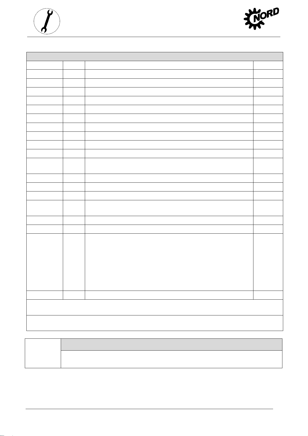
5.1 Service and Maintenance Intervals
Service and Maintenance Intervals Service and Maintenance Work Information –
see Section
Weekly
or every 100 operating hours
Every 2500 operating hours,
at least every six months
Every 5000 operating hours,
at least every year
(Only for standard IEC/NEMA motor
attachment)
Every 10000 operating hours,
at least every 2 years
Every 25000 operating hours,
at least every 5 years
According to the interval specified in
field MI of the rating plate
at least every 10 years
(Only for Category 2G and 2D)
- Perform a visual inspection for leaks
- Check the gear unit for unusual running noises
and/or vibrations
- Only for gear units with cooling cover:
Visual inspection of temperature sticker
- Check oil level
- Visual inspection of rubber buffer
- Visual inspection of hose
- Visual inspection of temperature sticker
- Remove dust
(only for category 2D)
- Check coupling
(Only for category 2G and standard IEC/NEMA
motor attachment)
- Re-grease
(applicable only to free drive shaft / Option W
and for agitator bearings / Option VLII / VLIII)
- Clean or replace the pressure venting screw
- Replace the automatic lubricant dispenser 5.2 / 4.2
- Changing the oil
- Check the cooling coil for deposits
- Replace shaft sealing rings if worn
- Re-lubrication of the bearings in the gear unit
- General overhaul 5.2
5.2
5.2
5.2
4.1
5.2
5.2
5.2 / 4.3
5.2
5.2
5.2
5.2
5.2
5.2
5.2
5.2 Service and Maintenance Work
Danger!
No explosive atmosphere must be present during servicing and repair work. Servicing
and maintenance work must only be performed by qualified specialist personnel.
When cleaning the gear unit, do not use procedures or materials which may cause
electrostatic charging of the gear unit or adjacent non-conducting components.
www.nord.com B2000-GB-0413 -33-
Page 34

Danger!
Installation and maintenance work must only be performed when gear units are at a
standstill. The drive must be isolated and secured to prevent accidental start-up.
Visual inspection for leaks:
Danger!
The gear unit must be checked for leaks. Attention should be paid to escaping gear oil
and traces of oil on the exterior or underneath the gear unit. In particular, the radial
seals, cover caps, screw plugs, hoses and housing joints should be checked.
If leaks are suspected, the gear unit should be cleaned, the oil level checked (see Section 4.1)
and checked again for leaks after approx. 24 hours. If a leak is confirmed (dripped oil), the gear
unit must be repaired immediately. Please contact the NORD service department.
If the gear unit is equipped with a cooling coil in the housing cover, the connections and the
cooling coil must be checked for leaks. If there are any leaks, these must be repaired
immediately. Please contact the NORD service department.
5. Service and maintenance
Check for running noises
Danger!
If the gear unit produces unusual running noises and/or vibrations, this could indicate
damage to the gear unit In this case the gear should be shut down and a general
overhaul carried out.
Checking the oil level:
See Section 4.1
Visual inspection of the rubber buffer
Gear units with rubber buffers (Option G or VG) and gear units with torque supports are
equipped with rubber elements. If these show damage such as tears to the rubber surface, the
elements must be replaced. Please contact the NORD service department.
Visual inspection of hose
Gear units with an oil level vessel (Option OT) have rubber hoses. If damage to the external
surface of the hoses as far as where they are inserted occurs, e.g. due to abrasions, cuts or
tears, they must be replaced. Please contact the NORD service department.
Visual inspection of the temperature sticker
(Only necessary for temperature class T4 or max. surface temperature < 135°C)
-34- B2000-GB-0413 www.nord.com
Page 35

Remove dust
5. Service and maintenance
Danger!
The temperature sticker must be checked that it has not turned black (See Figure 4-3).
If the temperature sticker has turned black, the gear unit has become too hot.
The cause of overheating must be established. Please contact the NORD service department
immediately. The drive unit must not resume operation before the cause of overheating has
been remedied and renewed overheating can be ruled out. Before recommissioning, a new
temperature sticker must be affixed to the gear unit (See Section 3.14).
(Only necessary for Category 2D)
Danger!
Dust deposits on the gear unit housing must be removed if they are more than 5 mm
thick.
With gear units fitted with a covering cap (Option H) the covering cap must be removed. Dust
deposits in the covering cap, on the driven shaft and on the shrink disk must be removed. Then
the covering cap must be fitted (See Section 3.11). Note: Some covering caps can be completely
sealed with liquid sealing agent. In such cases, there is no need for regular cleaning of the
covering cap if it is completely sealed with a liquid sealing agent such as Loctite 574 or Loxeal
58-14.
Checking the coupling
(Only necessary for Category 2G and IEC/NEMA standard motor attachments)
The motor must be removed. Plastic or elastomer coupling components must be examined for
traces of wear. If the limiting values listed below for the particular coupling versions and sizes
are exceeded, the plastic or elastomer coupling components must be replaced. Caution: only
use replacement parts with the same colour!
With claw couplings (ROTEX
as per Figure 5-1. B
Figure 5-1: Measurement of gear rim wear with ROTEX
For gear couplings, the limiting wear value is X = 0.8 mm, as per Figure 5-2.
) the tooth thickness of the elastomer gear rim must be measured
is the minimum permissible tooth thickness.
min
Limiting wear values for coupling gear rims
Type R14 R24 R38 R42 R48 R65 R90
B 9.7 8.6 13.3 15.7 17.7 22.2 32.3
Bmin 7.7 5.6 10.3 11.7 13.7 17.2 24.3
claw couplings
www.nord.com B2000-GB-0413 -35-
Page 36

5. Service and maintenance
SleeveSleeve
Regreasing
Hub Hub
New Wear limit X = 0.8mm
Figure 5-2: Measurement of gear sleeve wear for gear BoWex
couplings
Note!
If the examination only shows slight wear (25% of the limiting value), it is permissible to
extend the interval for examination of the coupling to twice the normal period, i.e. 5000
operating hours and at least every year.
Some gear unit designs (free drive shaft, Option W, agitator designs VLII and VLIII) are
equipped with a regreasing device.
For agitator versions VLII and VLIII, the vent screw located opposite to the grease nipple must
be unscrewed before regreasing. Grease should be injected until a quantity of 20-25g escapes
from the vent hole. After this, the vent plug must be reinserted and tightened.
For Option W and some IEC adapters, the outer roller bearing must be regreased with approx.
20-25g of grease via the grease nipple provided
Recommended grease: Petamo GHY 133N (see Section 6.4: Klüber Lubrication).
Cleaning or replacing the vent screw
Unscrew the pressure vent, thoroughly clean the vent screw (e.g. with compressed air) carry out
a function test and fit the vent screw in the same place. If necessary, use a new vent screw.
Replacing the automatic lubricant dispenser
Screw-off the cartridge case cover (2), (see Figure 4-2). The lubrication dispenser (5) is screwed
out and replaced with a new component (Part No. 283 0100). Then activate (see Chapter 4.2)!
Changing the oil
The figures in Section 6.1 show the oil drain screw, the oil level screw and the pressure vent
screw for various designs. Sequence:
1. Place the drip tray below the oil drain screw
2. Completely remove oil level screw, screwed sealing plug with dipstick if an oil level tank is
being used and oil drain screw.
-36- B2000-GB-0413 www.nord.com
Page 37

5. Service and maintenance
Danger!
Warning: Hot oil!
3. Drain all the oil from the gear unit.
4. If the screw lock coating of the oil drain screw or oil level screw is damaged in the thread, a
new oil level screw must be used or the thread cleaned and coated with securing lubricant,
e.g. Loctite 242, Loxeal 54-03 prior to inserting. Check the sealing ring for damage. Replace
with a new sealing ring in case of damage.
5. Support the seal ring, insert the oil drain screw into the hole and tighten to the correct
torque! (See Chapter 6.3 for torque values)
6. Using a suitable filling device, refill with new oil of the same type (see rating plate,
Sections 3.4and 6.2) through the oil level hole until oil emerges from the oil level hole. (The
oil can also be filled through the pressure vent screw or a sealing plug located higher than
the oil level). If an oil level vessel is used, fill the oil through the upper inlet (thread G1¼)
until the oil level is set as described in Section 4.1.
7. Wait at least 15 minutes, or at least 30 minutes if an oil level tank is used, and then check
the oil level. Proceed as described in Section 4.1.
Note!
The oil does not need to be changed on gear units without oil level screw (see Section
6.1). These gear units are lubricated for life.
Note!
Standard ATEX category 3G and 3D helical gear units (See rating plate, Section 3.4) do
not have an oil level screw. Here, the oil is topped up through the threaded pressure
vent bolt using the quantities listed in the table in the following table.
www.nord.com B2000-GB-0413 -37-
Page 38

5. Service and maintenance
[L] [L]
SK0 0,13 0,22 0,13 0,22 0,13 0,13 SK0 F 0,13 0,22 0,13 0,22 0,13 0,13
SK01 0,22 0,38 0,22 0,38 0,22 0,22 SK01 F 0,22 0,38 0,22 0,38 0,22 0,22
SK20 0,55 1,00 0,55 1,00 0,55 0,55 SK20 F 0,35 0,60 0,35 0,60 0,35 0,35
SK25 0,50 0,90 0,50 0,90 0,50 0,50 SK25 F 0,50 0,90 0,50 0,90 0,50 0,50
SK30
SK33 0,80 1,60 1,00 1,60 0,80 1,00 SK33 F 1,00 1,60 1,00 1,60 0,80 1,00
SK000 0,24 0,41 0,24 0,41 0,24 0,24 SK000 F 0,24 0,41 0,24 0,41 0,24 0,24
SK010
SK200 0,80 1,30 0,80 1,30 0,80 0,80 SK200 F 0,60 1,04 0,60 1,04 0,60 0,60
SK250 1,20 1,50 1,40 1,50 1,40 1,40 SK250 F 1,40 1,50 1,40 1,50 1,40 1,40
SK300 1,40 1,50 1,40 1,50 1,40 1,40 SK300 F 1,40 1,50 1,40 1,50 1,40 1,40
SK330 1,50 1,58 1,50 1,58 1,50 1,50 SK330 F 2,00 1,58 1,50 2,80 1,50 1,50
M1 M2 M3 M4 M5 M6
6.1
0,80 1,40
0,38 0,60
0,70 1,40 0,70 0,70
0,38 0,60 0,38 0,38
Check the cooling coil for deposits
The inner surface of the cooling coil must be checked for deposits, as in case of severe deposits
(fouling) the dissipation of heat is no longer guaranteed. In this case, the cooling coil must be
cleaned. If a chemical cleaner is used, it must be ensured that the cleaning agent does not
attack the material of the cooling coil (Cu pipe and yellow brass fittings)
Replacing the shaft sealing ring
Shaft sealing rings are rubbing seals made from an elastomer material and according to their
principle are subject to natural wear. The wearing life of shaft sealing rings depends on many
factors and cannot be calculated in advance. Once the shaft sealing ring has reached the end of
its service life, the oil film in the region of the sealing lip increases and a measurable leakage
with dripping oil occurs. The shaft sealing ring must then be replaced. To reduce the risk of
leaks due to worn shaft sealing rings we recommend that as a precaution, the shaft sealing rings
are replaced after every 25,000 operating hours or every 5 years. The space between the
sealing lip and the protective lip must be filled approximately 50% with grease on fitting
(recommended grease: PETAMO GHY 133N). Take care that after fitting, the new shaft sealing
ring does not run in the old wear track.
6.1
SK30 F
SK010 F
M1 M2 M3 M4 M5 M6
0,80 1,40 0,70 1,10 0,70 0,70
0,38 0,60 0,38 0,60 0,38 0,38
Re-lubricating bearings
For bearings which are not oil-lubricated and whose holes are completely above the oil level,
replace the roller bearing grease (recommended grease: PETAMO GHY 133N). Please contact
the NORD service department.
-38- B2000-GB-0413 www.nord.com
Page 39

General overhaul
With Category 2G and 2D gear units, a general overhaul is necessary after a specified longer
period of operation. The specification of the operating period in terms of operating hours, after
which a general overhaul must be carried out, can be seen from the rating plate data in field MI.
Alternatively, the maintenance class CM can be used to determine the operating period after
which a general overhaul must be carried out. The data in field MI of the rating plate is then e.g.:
MI CM=5.
The time for the general overhaul with the stated maintenance class CM is calculated as follows:
5. Service and maintenance
NA= C
M
f
kA
L
NA: Number of years since commissioning. With calculated values of NA which exceed 10
years, a general overhaul is due 10 years after commissioning.
CM: Maintenance class according to field MI of the rating plate
fL: Running time factor
fL= 10 Maximum running time 2 hours per day
fL= 6 Running time 2 to 4 hours per day
fL= 3 Running time 4 to 8 hours per day
fL= 1.5 Running time 8 to 16 hours per day
fL= 1 Running time 16 to 24 hours per day
kA: Utilisation factor
If the utilisation factor is unknown, KA=1.
If the actual power required by the application is known, longer maintenance intervals may
result. The utilisation factor may be calculated as follows:
k
A
3
P
1
P
tat
P1: Max. permissible drive power or motor power in kW according to the rating plate
P
: Actual drive power or motor power in kW which is required by the application at the rated
tat
speed. This is determined e.g. by measurements.
With variable loads with differing actual drive powers with rated speeds P
P
, … with known percentage times q1, q2, q3, …, the following equivalent average
tat3
tat1
, P
tat2
,
drive power applies:
q
3
3
PP
1
1
P
q
3
2
2
P
q
3
3
...
3
tattattattat
100100100
Danger!
The general overhaul must be carried out by qualified personnel in a specialist
workshop with appropriate equipment in observance of national regulations and laws.
We urgently recommend that the general overhaul is carried out by NORD Serv ice.
www.nord.com B2000-GB-0413 -39-
Page 40

If a general overhaul is due, the gear unit must be completely dismantled. The following work
must be carried out:
Clean all gear unit components
Examine all gear unit components for damage
All damaged components must be replaced
All roller bearings must be replaced
Replace back stops if fitted
Replace all seals, radial seals and Nilos rings
Replace plastic and elastomer components of the motor coupling
5. Service and maintenance
-40- B2000-GB-0413 www.nord.com
Page 41

6 Appendix
6.1 Versions and maintenance
For versions which are not listed, please refer to the special documentation drawing. (See rating
plate Section 3.4).
Explanation of symbols for the following version illustrations:
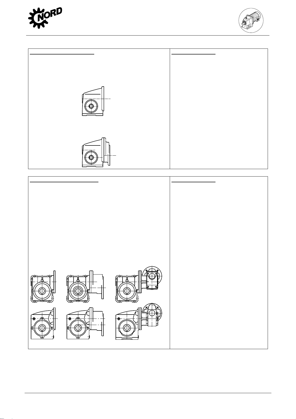
Standard helical gear units
Standard ATEX category 3G and 3D helical gear units do not have oil filling screws. (See rating
plate, Section 3.4)
Parallel shaft gear units
The following illustration applies for the version M4/H5 of gear unit types SK9282, SK9382,
SK10282, SK10382, SK11282, SK11382 and SK12382 with oil level vessel.
6. Appendix
Vent
Oil level
Oil drain
Figure 6-1: Parallel shaft gear units with oil level vessel
Oil level screws are not fitted to gear unit types SK 0182 NB, SK 0282 NB and SK 1382 NB in
the ATEX Categories 3G und 3D. (See rating plate, Section 3.4).
In Category 2G and 2D, types SK 0182 NB, SK 0282 NB and SK 1382 NB only have one oil
level screw. These gear unit types have checkable life-long lubrication
NORDBLOC helical gear units
Gear unit types SK 320, SK 172, SK 272, SK 372 and SK 273 and SK373 are not fitted with oil
level screws for ATEX Categories 3G and 3D. (See rating plate, Section 3.4).
In Category 2G and 2D, types SK 320, SK 172, SK 272, SK 372 and SK 273 and SK 373 only
have one oil level screw. These gear unit types have checkable life-long lubrication.
www.nord.com B2000-GB-0413 -41-
Page 42

NORDBLOC helical gear units SK072.1 and SK172.1
6. Appendix
Danger!
Oil level check in the M4 installation orientation for SK072.1 and SK172.1:
The oil level check for the M4 installation orientation must be carried out as follows in
the installation orientation M2:
1. Bring the gear unit into the M2 installation orientation and remove the oil level screw for the
M2 orientation.
Figure 6-2: Bring the gear unit into the M2 installation orientation
2. Determine the measurement X between the upper edge of the gear unit housing and the oil
level. If necessary, adapt the dipstick (see below).
Upper edge of housing
Figure 6-3: Measuring the oil level
3. Compare the determined measurement X with the corresponding measurement in the
following table. If necessary, adjust the oil level with the type of oil shown on the rating plate.
4. Screw in and tighten the oil level screw in the installation orientation M2 as per Section 4.1.
5. Bring the gear unit back into the installation orientation M4.
Gear unit type
SK 072.1 M8x1 22 ± 1mm
SK 172.1 M8x1 20 ± 1mm
Thread
size
Measurement
X [mm]
X
Oil level
-42- B2000-GB-0413 www.nord.com
Page 43

UNIVERSAL worm gear units
SK 1SI 31 – SK 1SI 75
SK 1SIS 31 – SK 1SIS 75
Figure 6-4: Orientation for oil level check.
For the oil level check, the gear unit or the geared motor must be brought into the orientation
shown above. To do this, it may be necessary to remove the gear unit or the geared motor.
NB: An adequate resting time of the warm gear unit in the position shown in Figure 6-4 must be
observed, in order to allow the oil to settle evenly.
The oil level can then be checked as described in Section 4.1.
In Category 2G and 2D the gear units only have one oil level screw. These gear unit types have
a checkable life-long lubrication.
In ATEX Category 3G and 3D, the gear units are not fitted with an oil level screw (See rating
plate, Section 3.4).
The gear unit types SK 1S xx, SK 2S xx, SK 1SU xx, SK 2SU xx, SK 1SM xx, SK 2SM xx,
SK 1SMI xx, SK 2SMI xx may only be used in category 3G and 3D.
As an option, types SI and SMI can be equipped with a vent screw. Gear units with vents must
be installed in the stated position.
Types SI, SMI, S, SM and SU as 2-stage gear unit types and types SI, SMI as worm gear units
for direct motor mounting have an oil filler which depends on the version and must be installed in
the stated position.
6. Appendix
M6
H6
M4
H3
M3
H2
M2
H4
M5
H5
www.nord.com B2000-GB-0413 -43-
Page 44

V
V
V
V
V
V
V
V
M1
B3+B5
M1
B3+B5
B7+B5III
M4
5+V1
M6
M6
B7+B5III
SK 11E
SK 21E
SK 31E
SK 41E
SK 51E
M3
B8+B5I
SK 03
SK 13
SK 23
SK 33N
SK 43
SK 53
M2
6+V3
B6+B5II
M1
B3+B5
M6
B7+B5III
SK 02
SK 12
SK 22
SK 32
SK 42
SK 52
SK 62N
M5
M4
5+V1
M3
B8+B5I
*
M6
M2
6+V3
B7+B5III
SK 62
SK 72
SK 82
SK 92
SK 102
SK 63*
SK 73*
SK 83*
SK 93*
SK 103*
M2
6+V3
M5
B6+B5II
M1
B3+B5
M2
6+V3
*
M4
5+V1
M3
B8+B5I
M5
B6+B5II
M4
5+V1
M3
B8+B5I
M5
B6+B5II
-44- B2000-0413 www.nord.com
Page 45

V
V
M6
B7+B5III
M1
B3+B5
M1
*
M2
3+V6
M6
M2
SK 472
SK 572
SK 672
SK 772
SK 872
SK 972
SK 473
SK 573
SK 673
SK 773
SK 873*
SK 973*
M4
M4
1+V5
M5
B6+B5II
M3
B8+B5I
M1
SK 372.1
SK 572.1
SK 672.1
SK 373.1
SK 573.1
SK 673.1
M5
M3
M1
*
M6
M2
M2
*
SK 372.1F
SK 572.1F
SK 672.1F
SK 373.1F
SK 573.1F
SK 673.1F
M6
SK 772.1
SK 872.1
SK 972.1
SK 773.1*
SK 873.1*
SK 973.1*
*
M4
M5
*
M4
M3
www.nord.com B2000-0413 -45-
M5
M3
Page 46

M1
*
M2
*
SK 772.1F
SK 872.1F
SK 972.1F
M6
SK 773.1F*
SK 873.1F*
SK 973.1F*
*
M6
M1
SK 072.1
SK 172.1
M4
*
M3
M2
M6
M5
M1
M2
SK 072.1 F
SK 172.1 F
M4
M5
M3
M4
M4
M3
38
M5
-46- B2000-0413 www.nord.com
Page 47

V
V
V
V
M6
B7+B5III
M1
B3+B5
M2
6+V3
SK 0
SK 01
SK 20
SK 25
SK 30
SK 33
M4
1+V5
M6
B7+B5III
M3
B8+B5I
M5
B6+B5II
M1
B3+B5
M2
6+V3
SK 000
SK 010
SK 200
SK 250
SK 300
SK 330
M4
1+V5
M3
B8+B5I
M5
B6+B5II
II3G / II3D
35, 37
www.nord.com B2000-0413 -47-
Page 48

M1
H1
M1
H1
M6
H3
SK 1282
SK 2282
SK 3282
SK 4282
SK 5282
M4
H5
M3
H2
M1
H1
M2
H6
M5
H4
M6
H3
SK 2382
SK 3382
SK 4382
SK 5382
M4
H5
M3
H2
M1
H1
M2
H6
M5
H4
M6
H3
M4
H5
M3
H2
M2
H6
SK 6282*
SK 7282*
SK 8282*
SK 9282*
SK 10282*
SK 11282*
SK 6382
SK 7382
SK 8382
SK 9382
SK 10382
SK 11382
SK 12382
*
M5
H4
M6
H3
*
**
37
M4
H5
M2
H6
**
SK 0182NB
SK 0282NB
SK 1382NB
**
*
M5
H4
M3
H2
-48- B2000-0413 www.nord.com
Page 49

V
V
V
V
V
V
V
V
M1
B3
M1
B3
M6
6
SK 92172
SK 92372
SK 92672
SK 92772
M4
B3I
M3
B8
M5
M2
B6
M4
B3I
5
M6
6
SK 92072
M3
B8
M4
B3I
M6
6
SK 9012.1
SK 9016.1
SK 9022.1
SK 9032.1
SK 9042.1
SK 9052.1
SK 9062.1
SK 9072.1
SK 9082.1
SK 9086.1
SK 9092.1
SK 9096.1
M1
B3
M2
B6
M6
M4
B3I
M1
B3
6
SK 9013.1
SK 9017.1
SK 9023.1
SK 9033.1
SK 9043.1
SK 9053.1
M2
B6
M5
5
M2
B6
M5
5
M3
B8
M3
B8
M5
5
www.nord.com B2000-0413 -49-
Page 50

M1
H1+B5I
M1
H1+B5I
H6+V3
M4
H3+B5II
H2+B5III
M6
M3
SK 92172
SK 92372
SK 92672
SK 92772
M1
M2
H4+B5
M5
H5+V1
M6
H6+V3
SK 92072
M4
H3+B5II
M3
H2+B5III
M1
M2
H4+B5
M5
H5+V1
M6
M4
M3
SK 92072.1
SK 92172.1
SK 92372.1
SK 92672.1
SK 92772.1
M6
SK 93072.1
M2
M5
M4
SK 93172.1
SK 93372.1
SK 93672.1
SK 93772.1
M3
M2
M5
-50- B2000-0413 www.nord.com
Page 51

V
V
V
V
M6
H6+V3
M1
H1+B5I
M2
H4+B5
M1
H1+B5I
M6
H6+V3
M2
H4+B5
M4
H3+B5II
M6
6
M4
B3I
M3
H2+B5III
SK 9012.1
SK 9016.1
SK 9022.1
SK 9032.1
SK 9042.1
SK 9052.1
SK 9062.1
SK 9072.1
SK 9082.1
SK 9086.1
SK 9092.1
SK 9096.1
SK 02050
SK 12063
SK 12080
SK 32100
SK 42125
M1
B3
M5
H5+V1
SK 9013.1
SK 9017.1
SK 9023.1
SK 9033.1
SK 9043.1
SK 9053.1
M4
H3+B5II
M2
B6
M6
6
M4
B3I
M3
H2+B5III
M1
B3
SK 13050
SK 13063
SK 13080
SK 33100
SK 43125
M5
H5+V1
M2
B6
M5
5
M3
B8
M3
B8
M5
5
www.nord.com B2000-0413 -51-
Page 52

V
V
M1
H1+B5I
M1
H1+B5I
M6
H6+V3
SK 02050
SK 12063
SK 12080
SK 32100
SK 42125
M4
H3+B5II
M3
H2+B5III
M2
H4+B5
M5
H5+V1
M6
H6+V3
SK 13050
SK 13063
SK 13080
SK 33100
SK 43125
M4
H3+B5II
M3
H2+B5III
M2
H4+B5
M5
H5+V1
M1
B3
M1
H1+B5I
M6
6
M4
B3I
M3
B8
SK 02040
M2
B6
M6
H6+V3
SK 02040
M4
H3+B5II
M5
5
M3
H2+B5III
M2
H4+B5
M5
H5+V1
-52- B2000-0413 www.nord.com
Page 53

V
V
M1
B3
M4
B6II
M6
5II
M3
B8
SK 1S32 SK 1S63
SK 2S32NB –
SK 2S63NB
SK 1SU32 –
SK 1SU63
SK 2SU32NB SK 2SU63NB
SK 1SM31 –
SK 1SM63
SK 2SM40 –
SK 2SM63
M2
B6
M5
5
M1
H1+B5I
M6
H6+V1I
M4
H3+B5II
M3
H2+B5III
SK 1S32 SK 1S63
SK 2S32NB –
SK 2S63NB
SK 1SU32 –
SK 1SU63
SK 2SU32NB SK 2SU63NB
SK 1SM31 –
SK 1SM63
SK 2SM40 –
SK 2SM63
39
M2
H4+B5
M5
H5+V1
www.nord.com B2000-0413 -53-
Page 54

6. Appendix
6.2 Lubricants
When changing oil or filling for the first time, the type of lubricant stated on the rating plate must be
used.
The following table shows the proprietary brands or product names according to the gear oil types stated on the
rating plate (see Section 3.4). This means that a product corresponding to the type of oil shown on the rating
plate must be used. In special cases, the designation of the specified product is stated on the type plate of the
gear unit.
Lubricant type
Details on
type plate
Mineral oil
Synthetic oil
(Polyglycol)
Synthetic oil
(Hydrocarbon)
CLP 220
CLP 100
CLP PG 680
CLP PG 220
CLP HC 220
Alpha EP 220
Alpha SP 220
Tribol 1100/220
Alpha EP 100
Alpha SP 100
Tribol 1100/100
Alphasyn
GS 680
Tribol 800/680
Alphasyn GS
220
Alphasyn PG
220
Tribol 800/220
Alphasyn EP
220
RENOLIN CLP
220
RENOLIN CLP
220 Plus
RENOLIN CLP
100
RENOLIN CLP
100 Plus
RENOLIN PG
680
RENOLIN PG
220
- Klübersynth
Klüberoil
GEM 1-220 N
Klüberoil
GEM 1-100 N
Klübersynth
GH 6-680
Klübersynth
GH 6-220
GEM 4-220 N
Mobilgear
600 XP 220
Mobilgear
600 XP 100
Mobil
Glygoyle 680
Mobil
Glygoyle 220
Mobil SHC 630 Omala S4 GX
Omala S2 G
220
Omala S2 G
100
Omala S4 WE
680
Omala S4 WE
220
220
Bio-degradable
oil
Food grade
oil as per
FDA 178.3570
CLP E 680
CLP E 220
CLP PG H1
680
CLP PG H1
220
- PLANTOGEAR
680 S
Tribol BioTop
1418/220
Tribol FoodProof
1800/680
Tribol FoodProof
1800/220
PLANTOGEAR
220 S
- Klübersynth
- Klübersynth
- - -
Klübersynth
GEM 2-220
UH1 6-680
UH1 6-220
- Naturelle Gear
Fluid EP 220
Mobil
Glygoyle 680
Mobil
Glygoyle 220
Cassida Fluid
WG 680
Cassida Fluid
WG 220
-54- B2000-GB-0413 www.nord.com
Page 55

6. Appendix
6.3 Torque values
Bolt Torques [Nm]
Size Screw connections in the strength classes Sealing Threaded pin
8.8 10.9 12.9 screws on coupling
M4 3.2 5 6 - M5 6.4 9 11 - 2
M6 11 16 19 - M8 27 39 46 11 10
M10 53 78 91 11 17
M12 92 135 155 27 40
M16 230 335 390 - M20 460 660 770 - M24 790 1150 1300 80 M30 1600 2250 2650 170 M36 2780 3910 4710 - M42 4470 6290 7540 - -
Angled pipe, as
in Figure 4-1
G1¼ - - - 20 -
- - - 12 -
6.4 Troubleshooting
Gear unit malfunctions
Fault Possible cause Remedy
Unusual running noises,
vibrations
Oil escaping from gear unit or
motor
Oil escaping from
pressure vent
Gear unit becomes too hot Unfavourable installation
Shock when switched on,
vibrations
Oil too low or
bearing damage or
toothed wheel damage
Defective seal Consult NORD Service
Incorrect oil level or incorrect,
contaminated oil or unfavourable
operating conditions
conditions or gear unit damage
Defective motor coupling or
loose gear unit mounting or
defective rubber element
Consult NORD Service
Oil change
Use oil expansion tank (Option OA)
Consult NORD Service
Replace elastomer gear rim, tighten
motor and gear unit fastening bolts,
replace rubber element
Drive shaft does not rotate
although motor is running
Fracture in gear unit or
defective motor coupling or
shrink disc slippage
Consult NORD Service
Danger!
Warning: shut down the gear unit immediately if any faults occur!
www.nord.com B2000-GB-0413 -55-
Page 56

6.5 Declaration of Conformity
6. Appendix
-56- B2000-GB-0413 www.nord.com
Page 57

6. Appendix
www.nord.com B2000-GB-0413 -57-
Page 58

DRIVESYSTEMS
www.nord.com
Page 59

Page 60

NORD DRIVESYSTEMS GROUP
www.nord.com/locator
Headquarters:
Getriebebau NORD GmbH & Co. KG
Rudolf-Diesel-Straße 1
22941 Bargteheide, Germany
Fon +49 (0) 4532 / 289 - 0
Fax +49 (0) 4532 / 289 - 2253
info@nord.com, www.nord.com
Member of the NORD DRIVESYSTEMS GROUP
DRIVESYSTEMS
Mat.-Nr. 6051402/0413
 Loading...