

Page 1
Intelligent Drivesystems, Worldwide Services
GB
B1092
Operating and Assembly Instructions for
1 MA-7 Three-phase Motors for operation with
Frequency Inverters BG 63 - 160
Page 2

1. General Information................................................................................................................3
2. Description ..............................................................................................................................3
2.1 Field of application....................................................................................................................3
2.2 Cooling .....................................................................................................................................3
3. Information on the correct handling of electric motors .....................................................3
3.1 Transport and storage...............................................................................................................3
3.2 Installation.................................................................................................................................4
3.3 Terminal box .............................................................................................................................4
3.4 Balancing, driving elements......................................................................................................4
3.5 Elekctrical connection ...............................................................................................................4
3.6 Checking the insulation resistance ...........................................................................................5
3.7 ICommissioning.........................................................................................................................5
4. Maintenance ............................................................................................................................6
5. Motors with increased ignition protection, type “e” Ex e 1MA..........................................8
5.1 Additional information for operation with a frequency inverter..................................................9
6. Drawing and list of replacement parts................................................................................11
6.1 Drawing and list of replacement parts.....................................................................................11
6.2 Tightening torques ..................................................................................................................15
6.3 Cross sections which may be connected................................................................................16
6.4 Changing the bearings............................................................................................................16
7. Data Sheets............................................................................................................................17
7.1 BG 63 M..................................................................................................................................17
7.2 BG 71 M..................................................................................................................................20
7.3 BG 80 M..................................................................................................................................23
7.4 BG 90 L ...................................................................................................................................26
7.5 BG 100 L.................................................................................................................................29
7.6 BG 100 L (increased performance).........................................................................................32
7.7 BG 112M.................................................................................................................................35
7.8 BG 132 M................................................................................................................................38
7.9 BG 160 M................................................................................................................................41
7.10 BG 160 L.................................................................................................................................44
8.
Type Plates ............................................................................................................................47
9. Declaration of Conformity....................................................................................................48
10. Addresses..............................................................................................................................49
Contents
Safety and information symbols
Please always observe the following safety and information symbols!
Danger
Danger of death or injury
to persons
Danger
Important information
regarding explosion
protection
-2- B1092-GB www.nord.com
Attention!
Damage to the machine possible
Note!
Page 3
1. General information
2. Description
1. General information
The applicable national, local and plant-specific regulations and requirements must be
observed.
Technical details may vary for special designs and constructions. In case of doubt it is
urgently recommended that the manufacturer is contacted, giving details of the type and serial
number (No. …. see rating plate), or have the maintenance work carried out by a service
centre.
2.1 Field of Application
Intended use of the motors:
The motors are constructed in protection class IP55 (protection class: see rating plate). They
may be installed in dusty or damp environments. For use outdoors an additional covering is
recommended to avoid the tong-term influence of direct intense sunlight, rain, snow, ice or
dust. If necessary, consultation/technical coordination is advisable.
Ambient temperature: ......... -20°C to +40°C
Installation altitude: .............
In case of differing ambient conditions, these must be indicated on the rating plate. The details
on the rating plate then apply.
2.2 Cooling
1MA motors are self-cooling (with fan).
3. Information on the correct handling of electric motors
3.1 Transport and storage
When transporting the motor, all available lifting lugs must be used.
When transporting sets of machinery (e.g. gearbox, fan, pumps etc.) only use the attached
lifting lugs. Sets of machinery must not be lifted by hanging on the motor lifting lugs.
With long periods of storage the period of use of the bearing grease is reduced. For storage of
longer than 12 months the condition of the grease must be checked. If the check reveals
contamination of the grease (ingress of condensation causes a change in consistency of the
grease) the grease must be replaced.
The roller bearings should be replaced if the time from delivery to commissioning of the motor
exceeds 4 years.
The probable life-span of the bearing system reduces with increasing storage time.
Machined surfaces (flange surfaces, shaft ends, etc.) should be protected with corrosion
protection agents.
If necessary, the insulating resistance of the windings must be checked, see Sect ion 3.6.
≤ 1000 m
All work must be carried out only when the system is in an electrically voltage-free state.
www.nord.com B1092-GB -3-
Page 4
3.2 Installation
For vertical configuration, all available lifting lugs and if necessary lifting straps (DIN EN 14921:2000) and/or tie-down straps (DIN EN 12195-2:2001) must be used to stabilise the position.
Attachments must not be used as lifting aids.
After installation, screwed-on lifting lugs must be tightened or removed.
For vertical installation with the shaft end pointing downwards, a protective cover for the fan
cover is recommended, to prevent the entry of foreign bodies.
On the other hand, in the case of shaft ends pointing upwards, the ingress of liquids along the
shaft must be prevented.
Smooth running: Precise alignment of the clutch and a well-balanced drive element (clutch,
pulleys, fan …) are prerequisites for smooth vibration-free running.
Complete balancing of the motor and the drive elements may be necessary.
3.3 Terminal box
Tightening torques for the screws of the terminal box: See Fig. 4.2.
3.4 Balancing, drive elements
3. Notes
The fitting and removal of drive elements (clutch, pulley, gear wheel,…) must be performed
with suitable equipment (see Fig.7).
As standard, the rotor is balanced with half parallel key.
When fitting the drive element, pay attention to the type of balancing!
The balancing condition is stated on the end face of the shaft or the type plate (H = half, F =
full parallel key balancing, N = balancing without parallel key).
The drive elements must be balanced according to ISO 1940:2003.
For balancing with half parallel key, the protruding visible portion of the parallel key T
be machined off (see Fig. 8).
The generally necessary measures for protection against touching the drive elements must be
observed.
3.5 Electrical connection
All work must only be carried out by qualified technicians on stationary low-voltage machines
which have been switched off and secured against switching on again. This also applies to the
auxiliary power circuits.
The terminal box must be sealed against dust and water.
The mains voltage and frequency must conform to the data on the rating plate. A voltage
deviation of ± 5% and/or a frequency deviation of ± 2% are permissible. The connection and
configuration of the jumpers must be performed according to the circuit diagram in the
terminal box. Connect the bonding conductor to this terminal
For connection terminals with terminal bridges (e.g. according to DIN 46282) the conductors
must be arranged so that approximately the same terminal heights result on both sides of the
bar. This type of connection therefore requires that individual conductors are bent to a Ushape or a fork terminal must be connected (see Fig. 5) This also applies to the bonding
connector and the external green/yellow earthing conductor.
.
must
p
-4- B1092-GB www.nord.com
Page 5

3. Notes
For tightening torques of screw connections of the electrical connections and terminal board
connections (except for the terminal bar) see Fig. 4.
3.6 Checking the insulation resistance
Prior to the initial commissioning of the motor after a long period of storage or standstill
(approx. 6 months) the insulation resistance of the windings must be checked.
During and immediately after the measurements, the terminals have voltages which can be
dangerous, and must not be touched.
Insulation resistance
The minimum insulation resistance of new, cleaned or repaired windings against earth
is 10 MΩ.
Initially, the critical insulation resistance R
multiplying the measured voltage U
R
= 0.69 kV x 0.5 MΩ /kV =0.345 MΩ
krit
, e.g. 0.69 kV AC, with the constant factor (0.5 MΩ /kV):
N
is calculated. The calculation is made by
krit
Measurement:
The minimum insulation resistance of the winding against earth is measured with 500 V DC.
The temperature of the windings should be 25°C ± 15°C.
The critical insulation resistance must be measured with the windings at operating
temperature using 500 V DC.
Testing:
If for new or cleaned windings or repaired motors, which have been stored or not used for
long periods, the minimum insulation resistance of the winding against earth is less than 10
MΩ, this may be caused by moisture. The windings must then be dried.
After long periods of operation the minimum insulation resistance may fall to the critical
insulation resistance. As long as the measured value does not fall below the calculated value
for the critical insulation resistance, operation of the motor may continue. If this value is fallen
below, the motor must be switched off immediately. The cause of this must be established
and if necessary the windings or parts of the windings must be repaired, cleaned or
dried.
3.7 Commissioning
NOTE: Electromagnetic compatibility
Production of interference: Great differences of torque (e.g. when driving a piston
compressor) induce a non-sine wave motor current, whose harmonics can cause an
impermissible effect on the mains and therefore impermissible production of interference.
With supply by frequency inverters, various strengths of interference are produced according
to the design of the frequency inverter (type, interference suppression, manufacturer). The
EMC information of the inverter manufacturer must be observed. If a shielded motor supply
cable is recommended, the shielding is most effective if a large area is electrically connected
to the metal terminal box of the motor (with metal screw connectors). With motors with
integrated sensors (e.g. thermistors) interference voltages due to the inverter may be
produced in the sensor cables.
Interference immunity: For motors with integrated sensors (e.g. thermistors) the operator
must ensure adequate immunity to interference by the selection of a suitable sensor cable
(possibly with screening, with connection as for the motor supply cable) and evaluation
device.
When operating motors with inverters at higher speeds than the nominal speed, the
mechanical limiting speed (Safe operating speed IEC 60034-1) must be observed (max. 3000
1
/
).
min
www.nord.com B1092-GB -5-
Page 6
Safety measures
Before starting any work on the motor or the device, but especially before opening the covers
of active components, the motor must be isolated according to regulations. In addition to the
main power circuits, any additional or auxiliary circuits must be taken into account.
The usual "5 Safety Rules" e.g. according to EN 50110-1 (DIN VDE 0105) are:
• Isolate,
• S ecure against switching on,
• Check for no voltage,
• Earth and short circuit,
• Cover or fence off neighbouring live components.
These measures may only be removed when the maintenance work is complete and the
motor has been completely assembled.
NOTE: If the motors are designed with closed condensation outlets, these must be opened
occasionally in order to allow any accumulated condensation to drain off. Condensation
outlets must always be located at the lowest point of the motor.
Changing bearings, grease packing
Bearing replacement period [h] under normal operating conditions, with horizontal installation
of the motor, cooling medium temperature or motor speed:
up to 1800 min-1 approx. 40000 h
up to 3000 min-1 approx. 20000 h
NOTE: The permissible axial and transverse forces must not be ex ceeded.
Independent of the hours of operation of a motor which is in use, the roller bearing should be
replaced approximately every 3 years due to the reduction of lubrication.
Under special operating conditions, e.g. vertical motor installation, heavy loads due to
vibration and shock, or operation with frequent reversing, the operating hours stated above
are significantly reduced.
The motors have groove ball bearings with cover plates (2ZC3 design). The material of the
plates should be temperature resistant from -30°C to +150°C, e.g. polyacrylic rubber (ACM).
Grease types for standard machines: UNIREX N3 (ESSO); Substitute greases must comply
with
DIN 51825-K3N:2004.
Special greases are indicated on the rating plate or on an additional plate.
Dismantle the motor to the necessary extent. Remove the roller bearing using suitable
equipment (see Fig. 6). Clean any contamination from the bearing seats.
Uniformly heat the roller bearings to approx. 80-100°C and fit. Hard blows (e.g. with a
hammer) must be avoided.
Any warn sealing elements (e.g. shaft seals) must also be renewed. If shaft sealing rings
without springs are installed, the replacement component must also be installed without
springs.
Centring edge seal
When assembling the motor, the bright fitting surfaces between the motor housing and the
bearing covers must be sealed with a suitable non-hardening sealing compound, e.g. Fluid-D.
Tightening torques for the screws on the bearing covers: see Fig. 4.2.
Regreasing device
For motors with regreasing devices, the details on the lubrication plate or the rating plate must
be observed. Regreasing should be performed with the motor running.
4. Maintenance
40°C
-6- B1092-GB www.nord.com
Page 7

4. Maintenance
General overhaul
A general overhaul of the motor must be carried out every 5 years.
For this the motor must be dismantled. The following work must be carried out:
• All components of the motor must be cleaned
• All components of the motor must be examined for damage
• All damaged components must be replaced
• All roller bearings must be replaced
• All seals and shaft sealing rings must be replaced
• Measure the insulation resistance
• Check the stationary voltage according to EN 60034-1
The general overhaul must be carried out by qualified personnel in a specialist workshop with
appropriate equipment. We strongly recommend that the general overhaul is carried out by
NORD-Service.
www.nord.com B1092-GB -7-
Page 8

5. Motors with increased ignition
protection, type "e" Ex e
5. Motors with increased ignition protection, type "e" Ex e 1MA
Identification: CE 0102 II G Ex e lI T3
Attention
Repairs must be carried out in or by authorised workshops. Repairs must be documented on
the motor (e.g. additional plate).
The increased hazard in areas endangered by explosions or fire damp requires particularly careful
observation of the general safety and start-up information.
Replacement parts - Only original replacement parts (see replacement parts list) may be used: this
particularly applies to seals and connection components. Exceptions are standard equivalent
commercially available components (e.g. roller bearings).
Explosion-protected electrical machines comply with standards:
EN 60034-1:2004 and all relevant parts, as well as EN 60079-0:2004, EN60079-7:2003.
They may only be used in explosion hazard areas according to the conditions stipulated by
the responsible supervisory authorities. They are responsible for the determination of the
explosion hazard (allocation of zones).
If the certification is supplemented with an "X" the special conditions in the EU prototype
certification must be observed.
The cable entries must be approved for explosion hazard areas and secured against
spontaneous loosening. Unused openings must be closed with approved stoppers. For the
assembly of the cable entries the instructions in the instruction manual of the cable entry
manufacturer must be observed. The number of threaded holes, the thread sizes and the type
of thread are given in Table 1. Special entries are indicated.
For vertical installation of the motor with the end of the shaft facing upwards or downwards,
e.g. types IMV3, IMV6, IMV19, for 1MA motors a cover must be arranged so that foreign
bodies cannot enter into the motor fan cover. Cooling of the motor must not be obstructed by
the cover. If nothing is stated to the contrary in the EU prototype certification or on the rating
plate with regard to type of operation and tolerances, electrical machines are designed for
continuous operation and normal infrequent starts, in which there is not significant start-up
warming.
The motors may only be used for the type of operation stated on the rating plate.
Range A in EN 60034-1:2004 - voltage ± 5%, frequency ± 2%, curve shape, symmetrical
mains - must be complied with in order that warming remains within the permissible limits.
Larger deviations from the rated values can cause a permissible warming of the electrical
machine and must be stated on the rating plate.
The temperature class of the motor stated on the rating plate must conform with the
temperature class of any escaping inflammable gases.
In addition, the safety device must be adjusted to the rated current. A triggering device
certified according to RL94/9/EU must be used.
Thermal protection of the machine by means of direct temperature monitoring of the windings
is permissible, if this is certified and stated on the rating plate.
An earthing tab is cast onto the housing for the connection of the external bonding cable. The
thread sizes for the screws of this external bonding cable are stated in Table 2.
-8- B1092-GB www.nord.com
Page 9
5. Motors with increased ignition
protection, type "e" Ex e
In the case of external sources of heat or cold, no additional measures are necessary if the
temperatures of the attached components do not exceed the permissible temperatures listed
in Table 3. The values in Table 3 apply for an ambient temperature of -20°C to +40°C with
self-ventilation. Special applications with external sources of heat and cold must be examined
by means of type testing with regard to the effect on the maximum surface and operating
temperatures and suitable measures taken if necessary.
For the installation of electrical equipment in explosion hazard areas in Germany, attention is
drawn to DIN EN 60079-14:2003 and the "Betriebssicherheitverordnung" [Operating Safety
Regulations]! In foreign countries the appropriate national regulations must be observed.
Operation with an inverter must be explicitly certified. The separate manufacturer's information
must be observed.
5.1 Additional information for operation with a frequency inverter
In addition to this information, the operating instructions of the frequency inverter and if
necessary the operating instructions of the gear unit and any other operating instructions must
be observed. Failure to observe these can cause material damage and personal injury.
Series 1 MA7 motors are produced in the ignition protection type "Increased Safety" and are
suitable for operation with a frequency inverter. The suitability can be identified by the
statement of the maximum frequency (e.g. f
Individual acceptance by a designated testing facility is not necessary.
It is essential that the supplied data sheet for the EU prototype certification (see
Section 7.) is complied with. This includes important information for operation and
commissioning.
Ex e motors suitable for use with frequency inverters are equipped with a triple PTC.
This must be evaluated by a certified triggering device with protection type labelling Ex II (2)
G.
The joint operation of several motors on one frequency inverter is not permissible.
Connecting cables must be dimensioned for a continuous thermal load of at least 80°C.
In addition, the frequency inverter used must be equipped with a speed-dependent current
limitation (Precision of measurement of effective current: 5%).
The current limitation is set to the maximum permissible nominal current of the
frequency inverter. A limitation of the output current of the frequency inverter to double the
rated current of the motor must be ensured.
Observation of the rev/f characteristic and the permissible torque depending on the
frequency is essential.
Voltage drops due to the use of long supply cables and/or sine wave filters between the
motor and the frequency inverter must be taken into account. The maximum
permissible length of cable is 30m. The frequency inverter also causes a drop in
voltage.
The motor terminal voltage can be influenced by increasing the input voltage of the frequency
inverter.
Voltages in excess of 1556 V (peak values) must not occur at the motor terminals.
Unfavourable cable lengths and short switching times of the frequency inverter can
cause impermissible overvoltages. The occurrence of such overvoltages must
be ruled out before starting up.
100 Hz) on the type plate.
max
www.nord.com B1092-GB -9-
Page 10

5. Motors with increased ignition
protection, type "e" Ex e
Shaft height Thread size Number
63 – 90 M16x1.5
M25x1.5
100 – 132 M32x1.5 4
160 M40x1.5 4
Table 1: Thread sizes in terminal box
Shaft height Thread of screw for bonding cable
63 – 90 M4
100 – 112 M5
132 – 160 M6
1
1
Table 2: Bonding cable screw threads
Number of pairs of poles 4-pole
Maximum shaft temperature 75°C
Maximum flange temperature 75°C
Table 3: Maximum permissible heat and cold sources
-10- B1092-GB www.nord.com
Page 11

replacement parts
6.1 List and drawings of replacement parts
Replacement parts which can be supplied ex works
Item no. Designation
1.00 AS bearing
.40 Bearing cover
.43 Shaft seal
.58 Spring washer
.60 Roller bearing
.61 Spring strip for bearing cover hub (not always present)
3.00 Rotor, complete
.88 Parallel key for fan
4.00 Stator, complete
.07 Housing foot, right
.08 Housing foot, left
.18 Rating plate
.19 Screw
.20 Cover
.30 Contact bracket
.31 Earthing bracket
5.00 Terminal box, complete
.03 Seal
.04 Seal
.10 Terminal board, complete
.11 Terminal bar
.44 Terminal box, upper section
.70 Retaining clip
.71 Retaining clip
.83 Seal
.84 Terminal box cover
.85 Seal
.90 Terminal box upper section, rotatable 4x90 degrees, complete (for retrofitting)
.92 Terminal box cover
.93 Seal
.95 Terminal box, upper section
.98 Seal
.99 Adapter plate
6.00 BS bearing
.10 Roller bearing
.11 Spring strip for bearing cover hub (not always present)
.20 Bearing cover
.23 Shaft sealing ring
7.00 Ventilation, complete
.04 Fan
6. Drawing and list of
.40 Fan hood
Fitting and removal tools for roller bearings, fan and drive elements can not be supplied!
www.nord.com B1092-GB -11-
Page 12
6. Drawing and list of
Standard components to be obtained commercially according to dimensions, materials and surfaces.
4.05 (see Fig. 3) DIN EN ISO 70897090
(DIN 125)
4.10
4.39
5.78
7.12 DIN 471
6.02 DIN 472
4.04 (see Fig. 3) DIN 580
1.49
4.11
4.39
5.19
5.49
5.79
5.89
5.91
5.94
6.29
7.49
3.38 DIN 6885
5.52
5.53
5.96
1.60
6.10
DIN 128
DIN EN ISO 4762
(DIN 912)
DIN EN ISO 4017
(DIN 933)
DIN EN ISO 4014
(DIN 931)
DIN EN ISO 7045
(DIN 7985)
DIN EN 50262
DIN 625 Bearing type
replacement parts
Replacement parts are to be ordered via the Sales departments of the particular producers.
-12- B1092-GB www.nord.com
Page 13

replacement parts
6. Drawing and list of
For aluminium bearing covers (1.40 AH 90) a spring strip (1.61) is inserted in the hub
(hook the bead into the groove).
certified screw connection (5.1)
Fig. 2 BG63…90L
www.nord.com B1092-GB -13-
Page 14

6. Drawing and list of
replacement parts
For aluminium bearing covers (1.40/6.20) a spring strip (1.61/6.11) is inserted in the hub
(hook the bead into the groove).
certified screw connection (5.1)
Fig. 2 BG 100…160L
-14- B1092-GB www.nord.com
Page 15
replacement parts
e.g. outlet for cables and wires - at bottom
Fig. 3, BD 100…160L, version with lateral configuration of upper section of terminal box (rotatable 4x90
degrees)
6. Drawing and list of
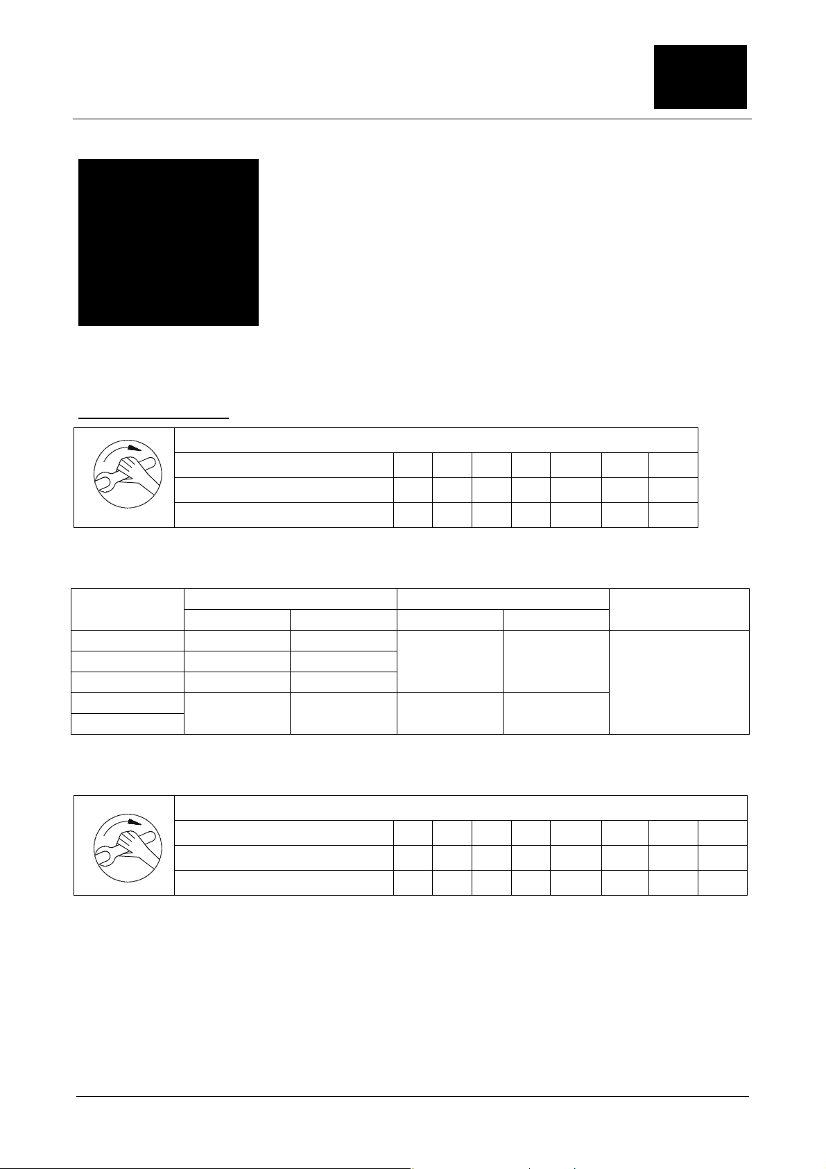
6.2 Tightening torques
Tightening torques for terminal board connections
Thread diameter M4 M5 M6 M8 M10 M12 M16
Tightening torque (Nm) min. 0.8 1.8 2.7 5.5 9.0 14.0 27.0
Tightening torque (Nm) max. 1.2 2.5 4.0 8.0 13.0 20.0 40.0
Fig. 4, Tightening torques of screw connections of the electrical connections and terminal board connections
(except for the terminal bar)
Nm min. Nm max. Nm min. Nm max.
M12x1.5 4 5
M16x1.5 5 7.5
M25x1.5 6 9
M32x1.5
M40x1.5
Fig 4.1, Tightening torques for cable connectors made from metal (*) and plastic 9**) for direct attachment to
motor. For other connectors (e.g. reducers) the corresponding torques according to the table should be used.
Tightening torque (Nm) max. 3 5 9 24 42 70 165 340
8 12 4 6
Thread diameter M4 M5 M6 M8 M10 M12 M16 M20
Tightening torque (Nm) min. 2 3.5
(*) (**)
2
Tightening torques on terminal box
6
3
16 28 46 110 225
O-ring thickness
mm
2
Fig. 4.2, tightening torques for screws on the electrical terminal box, on bearing covers and on screw
connectors for bonding cables
The above values apply unless other values are stated.
www.nord.com B1092-GB -15-
Page 16

6. Drawing and list of
6.3 Cross sections which may be connected
2
…25 mm
For connection with
a DIN fork terminal,
the fork terminal
must be angled
downwards.
Fig. 5, cross sections which may be connected according to the size of terminal (may be reduced due to the
size of the cable entries)
6.4 Changing the bearings
…10 mm2 …25 mm2 …10 mm2 …25 mm2
Connection of a
single conductor
with retaining clip.
replacement parts
Connection of two
conductors of
approximately the
same diameter with
retaining clip.
Connection of a
single conductor
under the external
earthing bracket.
For connection with
DIN fork terminal
under the external
earthing bracket.
Fig. 6, Intermediate plate (protection of centring in the end of the shaft)
Fig. 7, fitting and removal of drive elements (intermediate plate to protect the centring at the end of the shaft)
When fitting drive elements (clutch, gear wheel, pulley etc.) use the thread in the end of the shaft and as far
as possible heat the drive elements as necessary. Use suitable equipment for removal. When fitting or
removing, no blows (e.g. with a hammer or similar) or radial or axial forces in excess of those permissible
according to the catalogue may be transferred to the motor bearing via the end of the shaft.
Fig. 8, balancing with half parallel key
-16- B1092-GB www.nord.com
Page 17

7. Data Sheets
Translated extract from Data Sheet 01
of the EU Prototype Test Certificate PTB 07 ATEX 3046 X
for the three-phase motor, type 1MA7 063-4…
Rated values and data
This certificate applies for the following versions on condition that motors of this type only vary to an
insignificant extent from the tested sample with regard to the electrical and thermal load:
Star connection
Torque: 0.3 0.8 1.1 0.36 Nm
Power: 0.008 0.053 0.158 0.108 kW
Voltage: *) 80 200 400 400 V
Current: 0.33 0.48 0.58 0.34 A
Frequency: 10 25 50 100 Hz
Speed of rotation: 244 632 1370 2835 min
Operating mode: S1
Heat class F
-1
Delta connection
Torque: 0.3 0.8 1.1 1.1 Nm
Power: 0.008 0.053 0.295 0.334 kW
Voltage: *) 46 115 400 400 V
Current: 0.57 0.83 1.1 1,0 A
Frequency: 10 25 87 100 Hz
-1
Speed of rotation: 244 632 2485 2829 min
Operating mode: S1
Heat class F
*) Basic oscillation, measured at the motor terminals.
The voltage depends on the input voltage of the frequency inverter, the voltage drop at the filter and
over the motor supply cable and may not fall below the rated value by more than 5% according to
IEC 60034 - 1 Range "A", even with minimum input voltage of the frequency inverter. This must be
taken into account for the design of the motor, the parameterisation of the inverter (e.g. rev/f
adaptation) and for the minimum input voltage of the inverter.
The maximum input voltage of the inverter is 500V.
Adaptation of the rated voltage of the motor by means of the number of windings is permissible. The rated
current changes in inverse proportion to the rated voltage.
Sheet 1/3
www.nord.com B1092-GB -17-
Page 18

7. Data Sheets
Translated extract from Data Sheet 01
of the EU Prototype Test Certificate PTB 07 ATEX 3046 X
for the three-phase motor, type 1MA7 063-4…
Monitoring devices
To prevent impermissible heating due to overload, the motors are monitored by connection to a device for
direct temperature monitoring in combination with defined setting data of the inverter.
Due to the special characteristics of motors supplied by inverters and the adapted monitoring device,
details of the relationship I
The type of device for direct temperature monitoring has been tested by the Physikalish-Technische
Bundesanstalt and consists of three DIN 44082 type M 110 PTCs installed in the windings and a functiontested triggering device according to Guideline 94/9/EU.
With a line current of 1.7 A and a blocked shaft, the PTC must trigger after 31.4 s (± 20 %) assuming a
cold condition (20 °C).
By means of the temperature monitoring device, temperature class T3 as per EN 60079-7 is complied
with.
Inverter setting data
In combination with the aforementioned monitoring device, the following inverter data must be set and
maintained during operation:
Minimum pulse frequency: 3 kHz
and the heating time tE are not required for motors operated by inverters.
A/IN
Short-term current limit: 1.5*I
N
Maximum overload time: 60 s
Minimum frequency f
Maximum frequency f
Permissible duration of operation at
:
f
min
: 10 Hz
min
max
:
100 Y / 100 Δ
Hz
60 s
The maximum overload time and the permissible duration of operation at f
refer to a time period of 10
min
min.
The relationship of the torque to the frequency results from the permissible continuous current limit.
Sheet 2/3
-18- B1092-GB www.nord.com
Page 19

7. Data Sheets
of the EU Prototype Test Certificate PTB 07 ATEX 3046 X
The continuous current limit of the frequency inverter must be set dependent on the frequency according
to the following diagram:
1,2
1,1
0,9
I / In
0,8
0,7
Translated extract from Data Sheet 01
for the three-phase motor, type 1MA7 063-4…
Prohibited region
1
Permissible region
0,6
0,5
0,4
5 10 15 20 25 30 35 40 45 50 55 60 65 70 75 80 85 90 95 100 105
Star connection
Delta connection
f / Hz
Setting parameters for the continuous current limit of
the frequency inverter between 10 Hz and 100 Hz
All other setting data should be selected according to the requirements of the drive unit.
Special conditions
Group operation of the motors is not permissible.
Motors of this type may only be operated with inverters which fulfil the requirements stated above under
"Inverter setting data".
The maximum rated current of the frequency inverter may correspond to double the rated current of the
motor.
The current monitoring of the frequency inverter must record the effective value of the machine current
with a tolerance of
± 5 % in relation to the rated current of the motor.
Before start-up it must be ensured that no overvoltages due to the inverter with a peak value in excess of
1556 V (2*
2
*550V) occur at the terminals of the electrical machine.
Test report
PTB Ex 07-37118
Certification Facility for Explosion Protection Braunschweig, 4 October 2007
pp
L.S.
Dr.-Ing. F. Lienesch
Senior Government Official Sheet 3/3
www.nord.com B1092-GB -19-
Page 20

7. Data Sheets
Translated extract from Data Sheet 01
of the EU Prototype Test Certificate PTB 07 ATEX 3047 X
for the three-phase motor, type 1MA7 073-4…
Design values and data
This certificate applies for the following versions on condition that motors of this type only vary to an
insignificant extent from the tested sample with regard to the electrical and thermal load:
Star connection
Torque: 0.5 2.0 2.6 0.8 Nm
Power: 0.005 0.128 0.356 0.224 kW
Voltage: *) 40 200 400 400 V
Current: 0.5 0.92 1.11 0.67 A
Frequency: 5 25 50 100 Hz
Speed of rotation: 102 610 1273 2586 min
Operating mode: S1
-1
Heat class F
Delta connection
Torque: 0.5 2.0 2.6 2.6 Nm
Power: 0.005 0.128 0.640 0.764 kW
Voltage: *) 23 115 400 400 V
Current: 0.86 1.59 1.97 1.98 A
Frequency: 5 25 87 100 Hz
-1
Speed of rotation: 102 610 2280 2796 min
Operating mode: S1
Heat class F
*) Basic oscillation, measured at the motor terminals.
The voltage depends on the input voltage of the frequency inverter, the voltage drop at the filter and
over the motor supply cable and may not fall below the design value by more than 5% according to
IEC 60034 - 1 Range "A", even with minimum input voltage of the frequency inverter. This must be
taken into account for the design of the motor, the parameterisation of the inverter (e.g. rev/f
adaptation) and for the minimum input voltage of the inverter.
The maximum input voltage of the inverter is 500V.
Adaptation of the design voltage of the motor by means of the number of windings is permissible. The
rated current changes in inverse proportion to the rated voltage.
Sheet 1/3
-20- B1092-GB www.nord.com
Page 21

7. Data Sheets
of the EU Prototype Test Certificate PTB 07 ATEX 3047 X
Monitoring devices
To prevent impermissible heating due to overload, the motors are monitored by connection to a device
for direct temperature monitoring in combination with defined setting data of the inverter.
Due to the special characteristics of motors supplied by inverters and the adapted monitoring device,
details of the relationship I
The type of device for direct temperature monitoring has been tested by the Physikalish-Technische
Bundesanstalt and consists of three DIN 44082 type M 110 PTCs installed in the windings and a
function-tested triggering device according to Guideline 94/9/EU.
With a line current of 4.1 A and a blocked shaft, the PTC must trigger after 35 s (± 20 %) assuming a
cold condition (20 °C).
By means of the temperature monitoring device, temperature class T3 as per EN 60079-7 is complied
with.
Inverter setting data
In combination with the aforementioned monitoring device, the following inverter data must be set and
maintained during operation:
Minimum pulse frequency: 3 kHz
Translated extract from Data Sheet 01
for the three-phase motor, type 1MA7 073-4…
and the heating time tE are not required for motors operated by inverters.
A/IN
Short-term current limit: 1.5*I
N
Maximum overload time: 60 s
Minimum frequency f
Maximum frequency f
Permissible duration of operation
:
at f
min
: 5 Hz
min
max
:
100 Y / 100 Δ
Hz
60 s
The maximum overload time and the permissible duration of operation at f
refer to a time period of 10
min
min.
The relationship of the torque to the frequency results from the permissible continuous current limit.
Sheet 2/3
www.nord.com B1092-GB -21-
Page 22

A
7. Data Sheets
of the EU Prototype Test Certificate PTB 07 ATEX 3047 X
Translated extract from Data Sheet 01
for the three-phase motor, type 1MA7 073-4…
The continuous current limit of the frequency inverter must be set dependent on the frequency according
to the following diagram:
1,1
Unacceptable Region
0,9
1
0,8
I / In
0,7
0,6
0,5
0,4
0 5 10 15 20
25 30 35 40 45 50 55 60 65 70 75 80 85 90 95 100 105
cceptable Region
Star Connection
Delta Connection
f / Hz
Setting parameters for the continuous current limit of
the frequency inverter between 5 Hz and 100 Hz
All other setting data should be selected according to the requirements of the drive unit.
Special conditions
Group operation of the motors is not permissible.
Motors of this type may only be operated with inverters which fulfil the requirements stated above under
"Inverter setting data".
The maximum rated current of the frequency inverter may correspond to double the rated current of the
motor.
The current monitoring of the frequency inverter must record the effective value of the machine current
with a tolerance of
± 5 % in relation to the rated current of the motor.
Before start-up it must be ensured that no overvoltages due to the inverter with a peak value in excess of
1556 V (2*
2 *550V) occur at the terminals of the electrical machine.
Test report
PTB Ex 07-37119
Certification Facility for Explosion Protection Braunschweig, 4 October 2007
pp
L.S.
Dr.-Ing. F. Lienesch
Senior Government Official Sheet 3/3
-22- B1092-GB www.nord.com
Page 23

of the EU Prototype Test Certificate PTB 07 ATEX 3048 X
Translated extract from Data Sheet 01
7. Data Sheets
for the three-phase motor, type 1MA7 083-4…
Rated values and data
This certificate applies for the following versions on condition that motors of this type only vary to an
insignificant extent from the tested sample with regard to the electrical and thermal load:
Star connection
Torque: 1.4 4.5 5.2 1.8 Nm
Power: 0.015 0.295 0.75 0.531 kW
Voltage: *) 40 200 400 400 V
Current: 1.0 1.8 2.0 1.4 A
Frequency: 5 25 50 100 Hz
Speed of rotation: 101 627 1378 2819 min
Operating mode: S1
-1
Heat class F
Delta connection
Torque: 1.4 4.5 5.2 5.2 Nm
Power: 0.015 0.295 1.37 1.526 kW
Voltage: *) 23 115 400 400 V
Current: 1.7 3.1 3.6 3.5 A
Frequency: 5 25 87 100 Hz
-1
Speed of rotation: 101 627 2492 2836 min
Operating mode: S1
Heat class F
*) Basic oscillation, measured at the motor terminals.
The voltage depends on the input voltage of the frequency inverter, the voltage drop at the filter and
over the motor supply cable and may not fall below the design value by more than 5% according to
IEC 60034 - 1 Range "A", even with minimum input voltage of the frequency inverter. This must be
taken into account for the design of the motor, the parameterisation of the inverter (e.g. rev/f
adaptation) and for the minimum input voltage of the inverter.
The maximum input voltage of the inverter is 500V.
Adaptation of the design voltage of the motor by means of the number of windings is permissible. The
rated current changes in inverse proportion to the rated voltage.
Sheet 1/3
www.nord.com B1092-GB -23-
Page 24

7. Data Sheets
Translated extract from Data Sheet 01
of the EU Prototype Test Certificate PTB 07 ATEX 3048 X
for the three-phase motor, type 1MA7 083-4…
Monitoring devices
To prevent impermissible heating due to overload, the motors are monitored by connection to a device
for direct temperature monitoring in combination with defined setting data of the inverter.
Due to the special characteristics of motors supplied by inverters and the adapted monitoring device,
details of the relationship I
The type of device for direct temperature monitoring has been tested by the Physikalish-Technische
Bundesanstalt and consists of three DIN 44082 type M 110 PTCs installed in the windings and a
function-tested triggering device according to Guideline 94/9/EU.
With a line current of 9.8 A and a blocked shaft, the PTC must trigger after 21 s (± 20 %) assuming a
cold condition (20 °C).
By means of the temperature monitoring device, temperature class T3 as per EN 60079-7 is complied
with.
Inverter setting data
In combination with the aforementioned monitoring device, the following inverter data must be set and
maintained during operation:
Minimum pulse frequency: 3 kHz
and the heating time tE are not required for motors operated by inverters.
A/IN
Short-term current limit: 1.5*I
N
Maximum overload time: 60 s
Minimum frequency f
Maximum frequency f
Permissible duration of operation
:
at f
min
: 5 Hz
min
max
:
100 Y / 100 Δ
Hz
60 s
The maximum overload time and the permissible duration of operation at f
refer to a time period of 10
min
min.
The relationship of the torque to the frequency results from the permissible continuous current limit.
Sheet 2/3
-24- B1092-GB www.nord.com
Page 25

7. Data Sheets
of the EU Prototype Test Certificate PTB 07 ATEX 3048 X
The continuous current limit of the frequency inverter must be set dependent on the frequency according
to the following diagram:
1,1
1
0,9
Translated extract from Data Sheet 01
for the three-phase motor, type 1MA7 083-4…
Prohibited region
0,8
I / In
0,7
0,6
0,5
0,4
0 5 10 15 20 25 30 35 40 45 50 55 60 65 70 75 80 85 90 95 100 105
Permissible region
Star connection
Delta connection
f / Hz
Setting parameters for the continuous current limit of
the frequency inverter between 5 Hz and 100 Hz
All other setting data should be selected according to the requirements of the drive unit.
Special conditions
Group operation of the motors is not permissible.
Motors of this type may only be operated with inverters which fulfil the requirements stated above under
"Inverter setting data".
The maximum rated current of the frequency inverter may correspond to double the rated current of the
motor.
The current monitoring of the frequency inverter must record the effective value of the machine current
with a tolerance of
± 5 % in relation to the rated current of the motor.
Before start-up it must be ensured that no overvoltages due to the inverter with a peak value in excess of
1556 V (2*
2
*550V) occur at the terminals of the electrical machine.
Test report
PTB Ex 07-37120
Certification Facility for Explosion Protection Braunschweig, 4 October 2007
pp
L.S.
Dr.-Ing. F. Lienesch
Senior Government Official Sheet 3/3
www.nord.com B1092-GB -25-
Page 26

Translated extract from Data Sheet 01
7. Data Sheets
of the EU Prototype Test Certificate PTB 07 ATEX 3049 X
for the three-phase motor, type 1MA7 096-4…
Rated values and data
This certificate applies for the following versions on condition that motors of this type only vary to an
insignificant extent from the tested sample with regard to the electrical and thermal load:
Star connection
Torque: 3.0 9.1 9.1 3.6 Nm
Power: 0.034 0.604 1.34 1.08 kW
Voltage: *) 40 200 400 400 V
Current: 1.6 3.1 3.1 2.3 A
Frequency: 5 25 50 100 Hz
Speed of rotation: 108 630 1407 2854 min
Operating mode: S1
-1
Heat class F
Delta connection
Torque: 3 9.1 9.1 9.1 Nm
Power: 0.034 0.604 2.41 2.73 kW
Voltage: *) 23 115 400 400 V
Current: 2.8 5.4 5.4 5.7 A
Frequency: 5 25 87 100 Hz
-1
Speed of rotation: 108 630 2518 2870 min
Operating mode: S1
Heat class F
*) Basic oscillation, measured at the motor terminals.
The voltage depends on the input voltage of the frequency inverter, the voltage drop at the filter and
over the motor supply cable and may not fall below the design value by more than 5% according to
IEC 60034 - 1 Range "A", even with minimum input voltage of the frequency inverter. This must be
taken into account for the design of the motor, the parameterisation of the inverter (e.g. rev/f
adaptation) and for the minimum input voltage of the inverter.
The maximum input voltage of the inverter is 500V.
Adaptation of the design voltage of the motor by means of the number of windings is permissible. The
rated current changes in inverse proportion to the rated voltage.
Sheet 1/3
-26- B1092-GB www.nord.com
Page 27

7. Data Sheets
of the EU Prototype Test Certificate PTB 07 ATEX 3049 X
Monitoring devices
To prevent impermissible heating due to overload, the motors are monitored by connection to a device
for direct temperature monitoring in combination with defined setting data of the inverter.
Due to the special characteristics of motors supplied by inverters and the adapted monitoring device,
details of the relationship I
The type of device for direct temperature monitoring has been tested by the Physikalish-Technische
Bundesanstalt and consists of three DIN 44082 type M 110 PTCs installed in the windings and a
function-tested triggering device according to Guideline 94/9/EU.
With a line current of 17.4 A and a blocked shaft, the PTC must trigger after 17.5 s (± 20 %) assuming a
cold condition (20 °C).
By means of the temperature monitoring device, temperature class T3 as per EN 60079-7 is complied
with.
Inverter setting data
In combination with the aforementioned monitoring device, the following inverter data must be set and
maintained during operation:
Minimum pulse frequency: 3 kHz
Translated extract from Data Sheet 01
for the three-phase motor, type 1MA7 096-4…
and the heating time tE are not required for motors operated by inverters.
A/IN
Short-term current limit: 1.5*I
N
Maximum overload time: 60 s
Minimum frequency f
Maximum frequency f
Permissible duration of operation
:
at f
min
: 5 Hz
min
max
:
100 Y / 100 Δ
Hz
60 s
The maximum overload time and the permissible duration of operation at f
refer to a time period of 10
min
min.
The relationship of the torque to the frequency results from the permissible continuous current limit.
Sheet 2/3
www.nord.com B1092-GB -27-
Page 28

7. Data Sheets
Translated extract from Data Sheet 01
of the EU Prototype Test Certificate PTB 07 ATEX 3049 X
for the three-phase motor, type 1MA7 096-4…
The continuous current limit of the frequency inverter must be set dependent on the frequency according
to the following diagram:
1,2
1,1
1
Prohibited region
0,9
0,8
I / In
0,7
0,6
0,5
0,4
5 10 15 20 25 30 35 40 45 50 55 60 65 70 75 80 85 90 95 100 105
0
Permissible region
Star connection
Delta connection
f / Hz
Setting parameters for the continuous current limit of
the frequency inverter between 5 Hz and 100 Hz
All other setting data should be selected according to the requirements of the drive unit.
Special conditions
Group operation of the motors is not permissible.
Motors of this type may only be operated with inverters which fulfil the requirements stated above under
"Inverter setting data".
The maximum rated current of the frequency inverter may correspond to double the rated current of the
motor.
The current monitoring of the frequency inverter must record the effective value of the machine current
with a tolerance of
± 5 % in relation to the rated current of the motor.
Before start-up it must be ensured that no overvoltages due to the inverter with a peak value in excess of
1556 V (2*
2 *550V) occur at the terminals of the electrical machine.
Test report
PTB Ex 07-37121
Certification Facility for Explosion Protection Braunschweig, 4 October 2007
pp
L.S.
Dr.-Ing. F. Lienesch
Senior Government Official Sheet 3/3
-28- B1092-GB www.nord.com
Page 29

of the EU Prototype Test Certificate PTB 07 ATEX 3050 X
Translated extract from Data Sheet 01
7. Data Sheets
for the three-phase motor, type 1MA7 106-4…
Rated values and data
This certificate applies for the following versions on condition that motors of this type only vary to an
insignificant extent from the tested sample with regard to the electrical and thermal load:
Star connection
Torque: 5 13.5 13.5 5.5 Nm
Power: 0.061 0.937 2.0 1.67 kW
Voltage: *) 40 200 400 400 V
Current: 2.4 4.4 4.4 3.4 A
Frequency: 5 25 50 100 Hz
Speed of rotation: 114.2 662 1424 2872 min
Operating mode: S1
-1
Heat class F
Delta connection
Torque: 5 13.5 12.7 12.7 Nm
Power: 0.061 0.937 3.38 3.86 kW
Voltage: *) 23 115 400 400 V
Current: 4.15 7.6 7.6 7.8 A
Frequency: 5 25 87 100 Hz
-1
Speed of rotation: 114.2 662 2541 2896 min
Operating mode: S1
Heat class F
*) Basic oscillation, measured at the motor terminals.
The voltage depends on the input voltage of the frequency inverter, the voltage drop at the filter
and over the motor supply cable and may not fall below the design value by more than 5%
according to IEC 60034 - 1 Range "A", even with minimum input voltage of the frequency inverter.
This must be taken into account for the design of the motor, the parameterisation of the inverter
(e.g. rev/f adaptation) and for the minimum input voltage of the inverter.
The maximum input voltage of the inverter is 500V.
Adaptation of the design voltage of the motor by means of the number of windings is permissible. The
rated current changes in inverse proportion to the rated voltage.
Sheet 1/3
www.nord.com B1092-GB -29-
Page 30

7. Data Sheets
Translated extract from Data Sheet 01
of the EU Prototype Test Certificate PTB 07 ATEX 3050 X
for the three-phase motor, type 1MA7 106-4…
Monitoring devices
To prevent impermissible heating due to overload, the motors are monitored by connection to a device
for direct temperature monitoring in combination with defined setting data of the inverter.
Due to the special characteristics of motors supplied by inverters and the adapted monitoring device,
details of the relationship I
The type of device for direct temperature monitoring has been tested by the Physikalish-Technische
Bundesanstalt and consists of three DIN 44082 type M 120 PTCs installed in the windings and a
function-tested triggering device according to Guideline 94/9/EU.
With a line current of 28.8 A and a blocked shaft, the PTC must trigger after 15 s (± 20 %) assuming a
cold condition (20 °C).
By means of the temperature monitoring device, temperature class T3 as per EN 60079-7 is complied
with.
Inverter setting data
In combination with the aforementioned monitoring device, the following inverter data must be set and
maintained during operation:
Minimum pulse frequency: 3 kHz
and the heating time tE are not required for motors operated by inverters.
A/IN
Short-term current limit: 1.5*I
N
Maximum overload time: 60 s
Minimum frequency f
Maximum frequency f
Permissible duration of operation
:
at f
min
: 5 Hz
min
max
:
100 Y / 100 Δ
Hz
60 s
The maximum overload time and the permissible duration of operation at f
refer to a time period of 10
min
min.
The relationship of the torque to the frequency results from the permissible continuous current limit.
Sheet 2/3
-30- B1092-GB www.nord.com
Page 31

7. Data Sheets
of the EU Prototype Test Certificate PTB 07 ATEX 3050 X
The continuous current limit of the frequency inverter must be set dependent on the frequency according
to the following diagram:
1,2
1,1
1
Translated extract from Data Sheet 01
for the three-phase motor, type 1MA7 106-4…
Prohibited region
0,9
0,8
I / In
0,7
0,6
0,5
0,4
0
5 10 15 20 25 30 35 40 45 50 55 60 65 70 75 80 85 90 95 100 105
Permissible region
Star connection
Delta connection
f / Hz
Setting parameters for the continuous current limit of the
frequency inverter between 5 Hz and 100 Hz
All other setting data should be selected according to the requirements of the drive unit.
Special conditions
Group operation of the motors is not permissible.
Motors of this type may only be operated with inverters which fulfil the requirements stated above under
"Inverter setting data".
The maximum rated current of the frequency inverter may correspond to double the rated current of the
motor.
The current monitoring of the frequency inverter must record the effective value of the machine current
with a tolerance of
± 5 % in relation to the rated current of the motor.
Before start-up it must be ensured that no overvoltages due to the inverter with a peak value in excess of
1556 V (2*
2
*550V) occur at the terminals of the electrical machine.
Test report
PTB Ex 07-37122
Certification Facility for Explosion Protection Braunschweig, 4 October 2007
pp
L.S.
Dr.-Ing. F. Lienesch
Senior Government Official Sheet 3/3
www.nord.com B1092-GB -31-
Page 32

Translated extract from Data Sheet 02
7. Data Sheets
of the EU Prototype Test Certificate PTB 07 ATEX 3050 X
for the three-phase motor, type 1MA7 107-4…
Rated values and data
This certificate applies for the following versions on condition that motors of this type only vary to an
insignificant extent from the tested sample with regard to the electrical and thermal load:
Star connection
Torque: 5 14 16.8 7.5 Nm
Power: 0.065 0.99 2.5 2.2 kW
Voltage: *) 40 200 400 400 V
Current: 2.5 4.6 5.4 4.6 A
Frequency: 5 25 50 100 Hz
Speed of rotation: 124 679 1415 2831 min
Operating mode: S1
-1
Heat class F
Delta connection
Torque: 5 14 16.8 16 Nm
Power: 0.065 0.99 4.4 4.8 kW
Voltage: *) 23 115 400 400 V
Current: 4.3 8.0 9.4 9.6 A
Frequency: 5 25 87 100 Hz
-1
Speed of rotation: 124 679 2523 2885 min
Operating mode: S1
Heat class F
*) Basic oscillation, measured at the motor terminals.
The voltage depends on the input voltage of the frequency inverter, the voltage drop at the filter
and over the motor supply cable and may not fall below the design value by more than 5%
according to IEC 60034 - 1 Range "A", even with minimum input voltage of the frequency inverter.
This must be taken into account for the design of the motor, the parameterisation of the inverter
(e.g. rev/f adaptation) and for the minimum input voltage of the inverter.
The maximum input voltage of the inverter is 500V.
Adaptation of the design voltage of the motor by means of the number of windings is permissible. The
rated current changes in inverse proportion to the rated voltage.
Sheet 1/3
-32- B1092-GB www.nord.com
Page 33

7. Data Sheets
of the EU Prototype Test Certificate PTB 07 ATEX 3050 X
Monitoring devices
To prevent impermissible heating due to overload, the motors are monitored by connection to a device
for direct temperature monitoring in combination with defined setting data of the inverter.
Due to the special characteristics of motors supplied by inverters and the adapted monitoring device,
details of the relationship I
The type of device for direct temperature monitoring has been tested by the Physikalish-Technische
Bundesanstalt and consists of three DIN 44082 type M 120 PTCs installed in the windings and a
function-tested triggering device according to Guideline 94/9/EU.
With a line current of 35.2 A and a blocked shaft, the PTC must trigger after 16 s (± 20 %) assuming a
cold condition (20 °C).
By means of the temperature monitoring device, temperature class T3 as per EN 60079-7 is complied with.
Inverter setting data
In combination with the aforementioned monitoring device, the following inverter data must be set and
maintained during operation:
Minimum pulse frequency: 3 kHz
Translated extract from Data Sheet 02
for the three-phase motor, type 1MA7 107-4…
and the heating time tE are not required for motors operated by inverters.
A/IN
Short-term current limit: 1.5*I
N
Maximum overload time: 60 s
Minimum frequency f
Maximum frequency f
Permissible duration of operation
:
at f
min
: 5 Hz
min
max
:
100 Y / 100 Δ
Hz
60 s
The maximum overload time and the permissible duration of operation at f
refer to a time period of 10
min
min.
The relationship of the torque to the frequency results from the permissible continuous current limit.
Sheet 2/3
www.nord.com B1092-GB -33-
Page 34

7. Data Sheets
of the EU Prototype Test Certificate PTB 07 ATEX 3050 X
Translated extract from Data Sheet 02
for the three-phase motor, type 1MA7 107-4…
The continuous current limit of the frequency inverter must be set dependent on the frequency according
to the following diagram:
1,2
Prohibited region
Permisible region
I / In
1,1
0,9
0,8
1
0,7
0,6
0,5
0,4
0 5 10 15 20 25 30 35 40 45 50 55 60 65 70 75 80 85 90 95 100 105
Star connection
Delta connection
f / Hz
Setting parameters for the continuous current limit of
the frequency inverter between 5 Hz and 100 Hz
All other setting data should be selected according to the requirements of the drive unit.
Special conditions
Group operation of the motors is not permissible.
Motors of this type may only be operated with inverters which fulfil the requirements stated above under
"Inverter setting data".
The maximum rated current of the frequency inverter may correspond to double the rated current of the
motor.
The current monitoring of the frequency inverter must record the effective value of the machine current
with a tolerance of
± 5 % in relation to the rated current of the motor.
Before start-up it must be ensured that no overvoltages due to the inverter with a peak value in excess of
1556 V (2*
2 *550V) occur at the terminals of the electrical machine.
Test report
PTB Ex 07-37427
Certification Facility for Explosion Protection Braunschweig, 4 October 2007
pp
L.S.
Dr.-Ing. F. Lienesch
Senior Government Official Sheet 3/3
-34- B1092-GB www.nord.com
Page 35

of the EU Prototype Test Certificate PTB 07 ATEX 3051 X
Translated extract from Data Sheet 01
7. Data Sheets
for the three-phase motor, type 1MA7 113-4…
Rated values and data
This certificate applies for the following versions on condition that motors of this type only vary to an
insignificant extent from the tested sample with regard to the electrical and thermal load:
Star connection
Torque: 10.1 19 23.9 11 Nm
Power: 0.123 1.38 3.57 3.23 kW
Voltage: *) 40 200 400 400 V
Current: 4.4 6.3 7.6 7.8 A
Frequency: 5 25 50 100 Hz
Speed of rotation: 116 699 1422 2788 min
Operating mode: S1
-1
Heat class F
Delta connection
Torque: 10.1 19 23.9 20.1 Nm
Power: 0.123 1.38 6.35 6.14 kW
Voltage: *) 23 115 400 400 V
Current: 7.6 10.9 13.4 12.8 A
Frequency: 5 25 87 100 Hz
-1
Speed of rotation: 116 699 2533 2910 min
Operating mode: S1
Heat class F
*) Basic oscillation, measured at the motor terminals.
The voltage depends on the input voltage of the frequency inverter, the voltage drop at the filter and
over the motor supply cable and may not fall below the design value by more than 5% according to
IEC 60034 - 1 Range "A", even with minimum input voltage of the frequency inverter. This must be
taken into account for the design of the motor, the parameterisation of the inverter (e.g. rev/f
adaptation) and for the minimum input voltage of the inverter.
The maximum input voltage of the inverter is 500V.
Adaptation of the design voltage of the motor by means of the number of windings is permissible. The
rated current changes in inverse proportion to the rated voltage.
Sheet 1/3
www.nord.com B1092-GB -35-
Page 36

7. Data Sheets
Translated extract from Data Sheet 01
of the EU Prototype Test Certificate PTB 07 ATEX 3051 X
for the three-phase motor, type 1MA7 113-4…
Monitoring devices
To prevent impermissible heating due to overload, the motors are monitored by connection to a device
for direct temperature monitoring in combination with defined setting data of the inverter.
Due to the special characteristics of motors supplied by inverters and the adapted monitoring device,
details of the relationship I
The type of device for direct temperature monitoring has been tested by the Physikalish-Technische
Bundesanstalt and consists of three DIN 44082 type M 120 PTCs installed in the windings and a
function-tested triggering device according to Guideline 94/9/EU.
With a line current of 54 A and a blocked shaft, the PTC must trigger after 15 s (± 20 %) assuming a
cold condition (20 °C).
By means of the temperature monitoring device, temperature class T3 as per EN 60079-7 is complied
with.
Inverter setting data
In combination with the aforementioned monitoring device, the following inverter data must be set and
maintained during operation:
Minimum pulse frequency: 3 kHz
and the heating time tE are not required for motors operated by inverters.
A/IN
Short-term current limit: 1.5*I
N
Maximum overload time: 60 s
Minimum frequency f
Maximum frequency f
Permissible duration of operation
:
at f
min
: 5 Hz
min
max
:
100 Y / 100 Δ
Hz
60 s
The maximum overload time and the permissible duration of operation at f
refer to a time period of 10
min
min.
The relationship of the torque to the frequency results from the permissible continuous current limit.
Sheet 2/3
-36- B1092-GB www.nord.com
Page 37

7. Data Sheets
of the EU Prototype Test Certificate PTB 07 ATEX 3051 X
The continuous current limit of the frequency inverter must be set dependent on the frequency according
to the following diagram:
1,2
1,1
1
0,9
0,8
I / In
0,7
Translated extract from Data Sheet 01
for the three-phase motor, type 1MA7 113-4…
Prohibited region
Permissible region
0,6
0,5
0,4
0 5 10 15 20 25 30 35 40 45 50 55 60 65 70 75 80 85 90 95 100 105
Star connection
Delta connection
f / Hz
Setting parameters for the continuous current limit of
the frequency inverter between 5 Hz and 100 Hz
All other setting data should be selected according to the requirements of the drive unit.
Special conditions
Group operation of the motors is not permissible.
Motors of this type may only be operated with inverters which fulfil the requirements stated above under
"Inverter setting data".
The maximum rated current of the frequency inverter may correspond to double the rated current of the
motor.
The current monitoring of the frequency inverter must record the effective value of the machine current
with a tolerance of
± 5 % in relation to the rated current of the motor.
Before start-up it must be ensured that no overvoltages due to the inverter with a peak value in excess of
1556 V (2*
2 *550V) occur at the terminals of the electrical machine.
Test report
PTB Ex 07-37123
Certification Facility for Explosion Protection Braunschweig, 4 October 2007
pp
L.S.
Dr.-Ing. F. Lienesch
Senior Government Official Sheet 3/3
www.nord.com B1092-GB -37-
Page 38

Translated extract from Data Sheet 01
7. Data Sheets
of the EU Prototype Test Certificate PTB 07 ATEX 3052 X
for the three-phase motor, type 1MA7 133-4…
Rated values and data
This certificate applies for the following versions on condition that motors of this type only vary to an
insignificant extent from the tested sample with regard to the electrical and thermal load:
Star connection
Torque: 15 44 44 20.2 Nm
Power: 0.218 3.28 6.83 6.18 kW
Voltage: *) 40 200 400 400 V
Current: 7.4 13.8 13.9 12.5 A
Frequency: 5 25 50 100 Hz
Speed of rotation: 139 711 1477 2926 min
Operating mode: S1
-1
Heat class F
Delta connection
Torque: 15 44 35 35 Nm
Power: 0.218 3.28 9.49 10.88 kW
Voltage: *) 23 115 400 400 V
Current: 12.8 23.9 21.3 21.9 A
Frequency: 5 25 87 100 Hz
Speed of rotation: 139 711 2582 2956 min
Operating mode: S1
Heat class F
*) Basic oscillation, measured at the motor terminals.
The voltage depends on the input voltage of the frequency inverter, the voltage drop at the filter and
over the motor supply cable and may not fall below the design value by more than 5% according to
IEC 60034 - 1 Range "A", even with minimum input voltage of the frequency inverter. This must be
taken into account for the design of the motor, the parameterisation of the inverter (e.g. rev/f
adaptation) and for the minimum input voltage of the inverter.
The maximum input voltage of the inverter is 500V.
Adaptation of the design voltage of the motor by means of the number of windings is permissible.
The rated current changes in inverse proportion to the rated voltage.
-1
Sheet 1/3
-38- B1092-GB www.nord.com
Page 39

7. Data Sheets
of the EU Prototype Test Certificate PTB 07 ATEX 3052 X
Monitoring devices
To prevent impermissible heating due to overload, the motors are monitored by connection to a device
for direct temperature monitoring in combination with defined setting data of the inverter.
Due to the special characteristics of motors supplied by inverters and the adapted monitoring device,
details of the relationship I
The type of device for direct temperature monitoring has been tested by the Physikalish-Technische
Bundesanstalt and consists of three DIN 44082 type M 110 PTCs installed in the windings and a
function-tested triggering device according to Guideline 94/9/EU.
With a line current of 108 A and a blocked shaft, the PTC must trigger after 13 s (± 20 %) assuming a
cold condition (20 °C).
By means of the temperature monitoring device, temperature class T3 as per EN 60079-7 is complied
with.
Inverter setting data
In combination with the aforementioned monitoring device, the following inverter data must be set and
maintained during operation:
Minimum pulse frequency: 3 kHz
Translated extract from Data Sheet 01
for the three-phase motor, type 1MA7 133-4…
and the heating time tE are not required for motors operated by inverters.
A/IN
Short-term current limit: 1.5*I
N
Maximum overload time: 60 s
Minimum frequency f
Maximum frequency f
Permissible duration of
operation at f
min
:
: 5 Hz
min
max
:
100 Y / 100 Δ
Hz
60 s
The maximum overload time and the permissible duration of operation at f
refer to a time period of 10
min
min.
The relationship of the torque to the frequency results from the permissible continuous current limit.
Sheet 2/3
www.nord.com B1092-GB -39-
Page 40

7. Data Sheets
Translated extract from Data Sheet 01
of the EU Prototype Test Certificate PTB 07 ATEX 3052 X
for the three-phase motor, type 1MA7 133-4…
The continuous current limit of the frequency inverter must be set dependent on the frequency according
to the following diagram:
1,1
0,9
1
Prohibited region
0,8
I / In
0,7
0,6
0,5
0,4
0 5 10 15 20 25 30 35 40 45 50 55 60 65 70 75 80 85 90 95 100 105
Permissible region
Star connection
Delta connection
f / Hz
Setting parameters for the continuous current limit of
the frequency inverter between 5 Hz and 100 Hz
All other setting data should be selected according to the requirements of the drive unit.
Special conditions
Group operation of the motors is not permissible.
Motors of this type may only be operated with inverters which fulfil the requirements stated above under
"Inverter setting data".
The maximum rated current of the frequency inverter may correspond to double the rated current of the
motor.
The current monitoring of the frequency inverter must record the effective value of the machine current
with a tolerance of
± 5 % in relation to the rated current of the motor.
Before start-up it must be ensured that no overvoltages due to the inverter with a peak value in excess of
1556 V (2*
2 *550V) occur at the terminals of the electrical machine.
Test report
PTB Ex 07-37124
Certification Facility for Explosion Protection Braunschweig, 4 October 2007
pp
L.S.
Dr.-Ing. F. Lienesch
Senior Government Official Sheet 3/3
-40- B1092-GB www.nord.com
Page 41

7. Data Sheets
Translated extract from Data Sheet 01
of the EU Prototype Test Certificate PTB 07 ATEX 3053 X
for the three-phase motor, type 1MA7 163-4…
Rated values and data
This certificate applies for the following versions on condition that motors of this type only vary to an
insignificant extent from the tested sample with regard to the electrical and thermal load:
Star connection
Torque: 50 60 65.7 27 Nm
Power: 0.672 4.48 10 8.244 kW
Voltage: *) 53 200 400 400 V
Current: 14 17.6 18.9 17.6 A
Frequency: 5 25 50 100 Hz
Speed of rotation: 128 710 1455 2907 min
Operating mode: S1
-1
Heat class F
Delta connection
Torque: 50 60 65.7 56 Nm
Power: 0.672 4.48 17.663 17.3 kW
Voltage: *) 31 115 400 400 V
Current: 24.2 30.5 33.3 32.8 A
Frequency: 5 25 87 100 Hz
-1
Speed of rotation: 128 710 2563 2946 min
Operating mode: S1
Heat class F
*) Basic oscillation, measured at the motor terminals.
The voltage depends on the input voltage of the frequency inverter, the voltage drop at the filter
and over the motor supply cable and may not fall below the design value by more than 5%
according to IEC 60034 - 1 Range "A", even with minimum input voltage of the frequency inverter.
This must be taken into account for the design of the motor, the parameterisation of the inverter
(e.g. rev/f adaptation) and for the minimum input voltage of the inverter.
The maximum input voltage of the inverter is 500V.
Adaptation of the design voltage of the motor by means of the number of windings is permissible.
The rated current changes in inverse proportion to the rated voltage.
Sheet 1/3
www.nord.com B1092-GB -41-
Page 42

7. Data Sheets
Translated extract from Data Sheet 01
of the EU Prototype Test Certificate PTB 07 ATEX 3053 X
for the three-phase motor, type 1MA7 163-4…
Monitoring devices
To prevent impermissible heating due to overload, the motors are monitored by connection to a device
for direct temperature monitoring in combination with defined setting data of the inverter.
Due to the special characteristics of motors supplied by inverters and the adapted monitoring device,
details of the relationship I
The type of device for direct temperature monitoring has been tested by the Physikalish-Technische
Bundesanstalt and consists of three DIN 44082 type M 120 PTCs installed in the windings and a
function-tested triggering device according to Guideline 94/9/EU.
With a line current of 128 A and a blocked shaft, the PTC must trigger after 23 s (± 20 %) assuming a
cold condition (20 °C).
By means of the temperature monitoring device, temperature class T3 as per EN 60079-7 is complied
with.
Inverter setting data
In combination with the aforementioned monitoring device, the following inverter data must be set and
maintained during operation:
Minimum pulse frequency: 3 kHz
and the heating time tE are not required for motors operated by inverters.
A/IN
Short-term current limit: 1.5*I
N
Maximum overload time: 60 s
Minimum frequency f
Maximum frequency f
Permissible duration of operation
:
at f
min
: 5 Hz
min
max
:
100 Y / 100 Δ
Hz
60 s
The maximum overload time and the permissible duration of operation at f
refer to a time period of 10
min
min.
The relationship of the torque to the frequency results from the permissible continuous current limit.
Sheet 2/3
-42- B1092-GB www.nord.com
Page 43

7. Data Sheets
of the EU Prototype Test Certificate PTB 07 ATEX 3053 X
The continuous current limit of the frequency inverter must be set dependent on the frequency according
to the following diagram:
1,1
1,05
1
0,95
0,9
I / In
Translated extract from Data Sheet 01
for the three-phase motor, type 1MA7 163-4…
Prohibited region
Permissible region
0,85
0,8
0,75
0,7
0 5 10 15 20 25 30 35 40 45 50 55 60 65 70 75 80 85 90 95 100 105
f / Hz
Star connection
Delta connection
Setting parameters for the continuous current limit of
the frequency inverter between 5 Hz and 100 Hz
All other setting data should be selected according to the requirements of the drive unit.
Special conditions
Group operation of the motors is not permissible.
Motors of this type may only be operated with inverters which fulfil the requirements stated above under
"Inverter setting data".
The maximum rated current of the frequency inverter may correspond to double the rated current of the
motor.
The current monitoring of the frequency inverter must record the effective value of the machine current
with a tolerance of
± 5 % in relation to the rated current of the motor.
Before start-up it must be ensured that no overvoltages due to the inverter with a peak value in excess of
2
1556 V (2*
*550V) occur at the terminals of the electrical machine.
Test report
PTB Ex 07-37125
Certification Facility for Explosion Protection Braunschweig, 4 October 2007
pp
L.S.
Dr.-Ing. F. Lienesch
Senior Government Official Sheet 3/3
www.nord.com B1092-GB -43-
Page 44

Translated extract from Data Sheet 02
7. Data Sheets
of the EU Prototype Test Certificate PTB 07 ATEX 3053 X
for the three-phase motor, type 1MA7 166-4…
Rated values and data
This certificate applies for the following versions on condition that motors of this type only vary to an
insignificant extent from the tested sample with regard to the electrical and thermal load:
Star connection
Torque: 62 88 88 35.5 Nm
Power: 0.774 6.6 13.531 10.901 kW
Voltage: *) 40 200 400 400 V
Current: 21 26 26 23.4 A
Frequency: 5 25 50 100 Hz
Speed of rotation: 119 716 1468 2932 min
Operating mode: S1
-1
Heat class F
Delta connection
Torque: 62 88 88 75 Nm
Power: 0.774 6.602 23.757 23.235 kW
Voltage: *) 23 115 400 400 V
Current: 36.4 45 46 44.9 A
Frequency: 5 25 87 100 Hz
-1
Speed of rotation: 119 716 2576 2958 min
Operating mode: S1
Heat class F
*) Basic oscillation, measured at the motor terminals.
The voltage depends on the input voltage of the frequency inverter, the voltage drop at the filter and
over the motor supply cable and may not fall below the design value by more than 5% according to
IEC 60034 - 1 Range "A", even with minimum input voltage of the frequency inverter. This must be
taken into account for the design of the motor, the parameterisation of the inverter (e.g. rev/f
adaptation) and for the minimum input voltage of the inverter.
The maximum input voltage of the inverter is 500V.
Adaptation of the design voltage of the motor by means of the number of windings is permissible. The
rated current changes in inverse proportion to the rated voltage.
Sheet 1/3
-44- B1092-GB www.nord.com
Page 45

7. Data Sheets
of the EU Prototype Test Certificate PTB 07 ATEX 3053 X
Monitoring devices
To prevent impermissible heating due to overload, the motors are monitored by connection to a device for
direct temperature monitoring in combination with defined setting data of the inverter.
Due to the special characteristics of motors supplied by inverters and the adapted monitoring device,
details of the relationship I
The type of device for direct temperature monitoring has been tested by the Physikalish-Technische
Bundesanstalt and consists of three DIN 44082 type M 120 PTCs installed in the windings and a functiontested triggering device according to Guideline 94/9/EU.
With a line current of 186.7 A and a blocked shaft, the PTC must trigger after 22 s (± 20 %) assuming a
cold condition (20 °C).
By means of the temperature monitoring device, temperature class T3 as per EN 60079-7 is complied with.
Inverter setting data
In combination with the aforementioned monitoring device, the following inverter data must be set and
maintained during operation:
Minimum pulse frequency: 3 kHz
Translated extract from Data Sheet 02
for the three-phase motor, type 1MA7 166-4…
and the heating time tE are not required for motors operated by inverters.
A/IN
Short-term current limit: 1.5*I
N
Maximum overload time: 60 s
Minimum frequency f
Maximum frequency f
Permissible duration of operation
:
at f
min
: 5 Hz
min
max
:
100 Y / 100 Δ
Hz
60 s
The maximum overload time and the permissible duration of operation at f
refer to a time period of 10
min
min.
The relationship of the torque to the frequency results from the permissible continuous current limit.
Sheet 2/3
www.nord.com B1092-GB -45-
Page 46

7. Data Sheets
of the EU Prototype Test Certificate PTB 07 ATEX 3053 X
Translated extract from Data Sheet 02
for the three-phase motor, type 1MA7 166-4…
The continuous current limit of the frequency inverter must be set dependent on the frequency according
to the following diagram:
1,1
1,05
1
Prohibited region
0,95
I / In
0,9
0,85
0,8
0,75
0,7
0 5 10 15 20 25 30 35 40 45 50 55 60 65 70 75 80 85 90 95 100 105
Permissible region
Star connection
Delta connection
f / Hz
Setting parameters for the continuous current limit of
the frequency inverter between 5 Hz and 100 Hz
All other setting data should be selected according to the requirements of the drive unit.
Special conditions
Group operation of the motors is not permissible.
Motors of this type may only be operated with inverters which fulfil the requirements stated above under
"Inverter setting data".
The maximum rated current of the frequency inverter may correspond to double the rated current of the
motor.
The current monitoring of the frequency inverter must record the effective value of the machine current
with a tolerance of
± 5 % in relation to the rated current of the motor.
Before start-up it must be ensured that no overvoltages due to the inverter with a peak value in excess of
1556 V (2*
2 *550V) occur at the terminals of the electrical machine.
Test report
PTB Ex 07-37125
Certification Facility for Explosion Protection Braunschweig, 4 October 2007
pp
L.S.
Dr.-Ing. F. Lienesch
Senior Government Official Sheet 3/3
-46- B1092-GB www.nord.com
Page 47

8. Type Plates
www.nord.com B1092-GB -47-
Page 48

9. Declaration of Conformity
-48- B1092-GB www.nord.com
Page 49

10. Addresses
Getriebebau NORD national:
North branch Getriebebau NORD GmbH & Co. KG Tel.: +49(0) 4532 / 401-0
Hamburg / Schleswig-Holstein / Postfach 12 62 · 22943 Bargteheide Fax: +49(0) 4532 / 401-253
Niedersachsen Rudolf-Diesel-Straße 1 · 22941 Bargteheide E-mail: info@nord-de.com
Sales office Bremen Getriebebau NORD GmbH & Co. KG Tel.: +49(0) 4249 / 9616-75
westliches Niedersachsen
Bremen Wohlers Feld 16 E-mail: nl-bremen@nord-de.com
27211 Bassum
West branch Getriebebau NORD GmbH & Co. KG Tel.: +49(0) 211 / 99555-0
Köln / Koblenz / Niederlassung West Fax: +49(0) 211 / 99555-45
südl. Nordrhein-Westfalen / Großenbaumer Weg 10 E-mail: nl-duesseldorf@nord-de.com
Ruhrgebiet / Düsseldorf 40472 Düsseldorf
Sales Office Butzbach Getriebebau NORD GmbH & Co. KG Tel.: +49(0) 6033 / 9623-0
Hessen / Frankfurt /
Wiesbaden / Darmstadt Marie-Curie-Straße 2 E-mail: nl-frankfurt@nord-de.com
35510 Butzbach
East branch Getriebebau NORD GmbH & Co. KG Tel.: +49(0) 371 / 33407-0
Sachsen / südl. Sachsen-Anhalt / Niederlassung Ost Fax: +49(0) 371 / 33407-20
Thüringen Leipziger Straße 58 E-mail: nl-chemnitz@nord-de.com
09113 Chemnitz / Sachsen
Sales Office Berlin Getriebebau NORD GmbH & Co. KG Tel.: +49(0) 30 / 639794-13
Berlin / Brandenburg Vertriebsbüro Berlin Fax: +49(0) 30 / 639794-14
Mecklenb.-Vorpommern / Roedernstr. 8 E-mail: nl-berlin@nord-de.com
nördl. Sachsen-Anhalt 12459 Berlin
South branch Getriebebau NORD GmbH & Co. KG Tel.: +49(0) 7158 / 95608-0
Stuttgart / Baden-Würtemberg / Niederlassung Süd Fax: +49(0) 7158 / 95608-20
Saarland / südl. Rheinland-Pfalz Katharinenstr. 2-6 E-mail: nl-stuttgart@nord-de.com
70797 Filderstadt – Sielmingen
Sales Office Nuremberg Getriebebau NORD GmbH & Co. KG Tel.: +49(0) 911 / 67 23 11
Nuremberg / Northern Bavaria Sales Office Nuremberg Fax: +49(0) 911 / 67 24 71
Schillerstraße 3 E-mail: nl-nuernberg@nord-de.com
90547 Stein
/ Vertriebsbüro Bremen Fax: +49(0) 4249 / 9616-76
Vertriebsbüro Butzbach Fax: +49(0) 6033 / 9623-30
www.nord.com B1092-GB -49-
Page 50

10. Addresses
Getriebebau NORD International:
AT Getriebebau NORD GmbH
Deggendorfstraße 8, A-4030 Linz
Tel.: +43-732-31 89 20 Fax: +43-732-31 89 20-85
info@nord-at.com
AUS NORD Drivesystems
18 Stoney Way
3030 Derrimut Vic, Australia
Tel: +61 (0) 488 588 200
mark.alexander@nord.com
BE NORD Aandrijvingen Belgie N.V.
Boutersem Dreef 24, B-2240 Zandhoven
Tel.: +32-3-484 59 21 Fax: 32-3-484 59 24
info@nord-be.com
BR Nord Motoredutores do Brasil Ltda.
Rua Dr. Moacyr Antonio de Morais 700
CEP: 07140-285 São Paulo
Tel.: +55-11-64 02 88 55 Fax: +55-11-64 02 88 30
info@nord-br.com
CA Nord Gear Limited
41 West Drive, CDN - Brampton, Ontario L6T 4A1
Tel.: +1-905-796-36 06 Fax: +1-905-796-81 30
info@nord-ca.com
CN NORD Drivesystems
No. 510 Chang Yang Street, Suzhou Industrial Park, 215021
P.R. China, Jiangsu Province
Tel.: +86-512-85180277-191 Fax: +86-512-85180278
jblock@nord-cn.com
HR NORD-Pogoni d.o.o.
Obrtnicka 9, HR-48260 Krizevci
Tel.: +385-48-71 19 00 Fax: +385-48-27 04 94
info@nord-hr.com
CZ NORD-Poháněcí technika, s. r. o.
Bečovská 1398/11, CZ 104 00 Praha 10 - Uhříněves
Tel.: +420 222 287 222 Fax: +420 222 287 228
info@nord-cz.com
DK NORD-Gear Danmark A/S
Kliplev Erhvervspark 28 – Kliplev, DK - 6200 Aabenraa
Tel.: +45-73 68 78 00 Fax: +45-73 68 78 10
info@nord-dk.com
FI NORD Gear Oy
Aunankorvenkatu 7, FIN - 33840 Tampere
Tel.: +358-3 25 41 800 Fax: +358-3 25 41 820
info@nord-fi.com
FR NORD Réducteurs sarl.
17-19 Av. G. Clémenceau, F-93421 Villepinte Cedex
Tel.: +33-1 49 63 01 89 Fax: +33-1 49 63 08 11
info@nord-fr.com
HU NORD Hajtastechnika Kft.
Törökkö u. 5-7, H-1037 Budapest
Tel.: +36-1 437 01 27 Fax: +36-1 250 55 49
info@nord-hu.com
IN Nord Drivesystem Pvt. LTD
282/2, 283/2, Village Mann, Tal. Mulshi,
IN – Pune – 411 057
Tel.: +91-(0)20-39801-200 Fax: +91-(0)20-39801-216
info@nord-in.com
ID PT. NORD Indonesia
Jln. Raya Serpong KM7
Kompleks Rumah Multi Guna Blok D-No. 1
Pakulonan, Serpong 15310 – Tangerang - West Java
Tel.: +62-21-53 12 22 22
info@nord-id.com
IT NORD-Motoriduttori s.r.l.
Via Newton 22, IT-40017 San Giovanni In Persiceto (BO)
Tel.: +39-051-68 70 711 Fax: +39-051-68 70 793
info@nord-it.com
Fax: +62-21-53 12 22 88
MX NORD Gear corporation
Av. Lázaro Cárdenas 1007 Pte, San Pedro Garza Caría, N.L.
MX – 66266 Mexico, C.P.
Tel.: +52-81-82 20 91 65 Fax: +52-81-82 20 90 44
HGonzales@nord-mx.com
NL NORD Aandrijvingen Nederland B.V.
Voltstraat 12, NL-2181 HA Hillegom
Tel.: +31-252-52 95 44 Fax: +31-252-52 22 22
info@nord-nl.com
NO NORD Gear Norge AS
Hestehagen 5, PB 1043, N – 1442 Drøbak
Tel.: +47-64 90 55 80 Fax: +47-64 90 55 85
info@nord-no.com
PL NORD Napêdy sp. z o.o.
Ul. Grottgera 30, PL-32-020 Wieliczka
Tel.: +48-012-28 89 900 Fax: +48-012-28 89 911
biuro@nord.pl
RU OOO NORD Privody
Ul.A. Nevsky 9, RU-191167 St. Petersburg
Tel.: +7-812-327 0192 Fax: +7-812-327 0192
info@nord-ru.com
SG NORD GEAR Pte. Ltd.
33 Kian Teck Drive, 628850 Jurong - Singapore
Tel.: +65-62 65 91 18 Fax: +65-62 65 68 41
info@nord-sg.com
SK NORD Pohony, s.r.o.
Stromová 13, SK - 831 01 Bratislava
Tel.: +421-2-54 79 13 17 Fax: +421-2-54791402
info@nord-sk.com
ES NORD Motorreductores S.A.
Aptdo. de Correos 166, ES - 08200 Sabadell
Tel.: +34 93 72 35 322 Fax: +34 93 72 33 147
info@nord-es.com
SE NORD Drivsystem AB
Ryttargatan 277 / Box 2097, SE-19402 Upplands Väsby
Tel.: +46-8-59 41 14 00 Fax: +46-8-59 41 14 14
info@nord-se.com
CH Getriebebau NORD AG
Bächigenstr.18, CH-9212 Arnegg
Tel.: +41-71-38 89 911 Fax: +41-71-38 89 915
info@nord-ch.com
TR NORD-Drivesystems Güç Aktarma
Sýstemlerý San. Ve. Ltd. Ptý
Ticaret Ltd. Sti., TR-34959 - Tuzla - Istanbul
Tel.: +90-216-30 41 360 Fax: +90-216-30 41 369
info@nord-tr.com
UKR Getriebebau NORD GmbH
Vasilkovskaja 1, Office 100/3, Ukr-03040 Kyiv
Tel.: +380-44-53 70 615 Fax: +380-44-53 70 615
vtsoka@nord-ukr.com
UK Nord Gear Limited (UK)
11 Barton Lane, Abingdon Science Park, GB-Abingdon,
Oxfordshire OX14 3NB
Tel.: +44-1235-53 44 04 Fax: +44-1235-53 44 14
info@nord-uk.com
US NORD Gear Corporation
800 Nord Drive, P.O. 367, USA-Waunakee, WI 53597
Tel.: +1-608-84 97 300, +1-888-314-6673
Fax: +1-800-373-6673
info@nord-us.com
VN NORD Gear Pte. Ltd
Unit 401, 4F, An Dinh Building,
18 Nam Quoc Cang Street
Pham Ngu Lao Ward
District 1, Ho Chi Minh City, Vietnam
Tel: +84- 8 925 7270 Fax: +84 8 925 7271
info@vn.nord.com
-50- B1092-GB www.nord.com
Page 51

Page 52

Intelligent Drivesystems, Worldwide Services
Getriebebau NORD GmbH & Co. KG
Rudolf-Diesel-Str. 1
D - 22941 Bargteheide
Fon +49 (0) 4532 / 401 - 0
Fax +49 (0) 4532 / 401 - 253
info@nord.com
www.nord.com
DRIVESYSTEMS
Mat.-Nr. 6052702/2910
 Loading...