

Page 1

Intelligent Drivesystems, Worldwide Services
GB
B1050
Operating and Maintenance Instructions for
Industrial Gear Units SK 7207 - SK 15507
DRIVESYSTEMS
Page 2

1.
Notes .............................................................................................................................. 4
1.1 General information ........................................................................................................ 4
1.2 Safety and information symbols ..................................................................................... 4
1.3 Correct use ..................................................................................................................... 4
1.4 Safety information ........................................................................................................... 5
1.5 Other documents ............................................................................................................ 5
1.6 Disposal .......................................................................................................................... 5
2. Description of gear units .............................................................................................. 6
2.1 Type designations and gear unit types ........................................................................... 6
2.2 Name plate ..................................................................................................................... 7
3. Storage, transport, preparation, installation .............................................................. 8
3.1 Storing the gear unit ....................................................................................................... 8
3.2 Long-term storage .......................................................................................................... 8
3.3 Transporting the gear unit .............................................................................................. 9
3.4 Preparing for installation ............................................................................................... 12
3.5 Installing the gear unit .................................................................................................. 12
3.6 Fitting hubs on the gear shafts ..................................................................................... 13
3.7 Fitting push-on gear units ............................................................................................. 14
3.8 Torque support ............................................................................................................. 16
3.9 Fitting shrink discs ........................................................................................................ 16
3.10 Fitting the covers ........................................................................................................ 17
3.11 Fitting a standard motor .............................................................................................. 17
3.12 Fitting the cooling coil to the cooling system .............................................................. 19
3.13 Mounting the external cooling system (cooling unit) .................................................. 19
3.14 Retrospective paintwork ............................................................................................. 20
Contents
4. Commissioning ........................................................................................................... 21
4.1 Checking the oil level .................................................................................................... 21
4.2 Lubricant cooling with internal water cooler ................................................................. 21
4.3 Lubricant cooling with external oil/water cooler (cooling system) ................................ 21
4.4 Lubricant cooling with external oil/water cooler (cooling system) ................................ 22
4.5 Gear unit cooling with a fan .......................................................................................... 22
4.6 Checking the Taconite seals ........................................................................................ 23
4.7 Pressure safeguard ...................................................................................................... 23
4.8 Checklist ....................................................................................................................... 24
5. Service and maintenance ........................................................................................... 25
5.1 Service and maintenance intervals ............................................................................... 25
5.2 Service and maintenance work .................................................................................... 25
6. Appendix ...................................................................................................................... 29
6.1 Versions and maintenance ........................................................................................... 29
6.2 Lubricant quantities ....................................................................................................... 31
6.3 Lubricants ..................................................................................................................... 33
6.4 Bolt torque values ......................................................................................................... 35
6.5 Troubleshooting ............................................................................................................ 36
www.nord.com B1050-GB-0213 -3-
Page 3
1. Notes
1.1 General information
Read the Operating Manual carefully prior to performing any work on or putting the gear unit into
operation. Strict compliance with the instructions in this Operating Manual is essential.
Getriebebau NORD accepts no liability for damage to persons, materials or assets as a result of
the non-observance of this Operating Manual, operating errors or incorrect use. General wearing
parts, e.g. radial seals are excluded from the warranty.
If additional components are attached to or installed in the gear unit (e.g. motor, cooling
system, pressure sensor etc.) or components (e.g. cooling system) are supplied with the
order, the operating instructions for these components must be observed.
If you do not understand the contents of this Operating Manual or additional operating
instructions, please consult Getriebebau NORD!
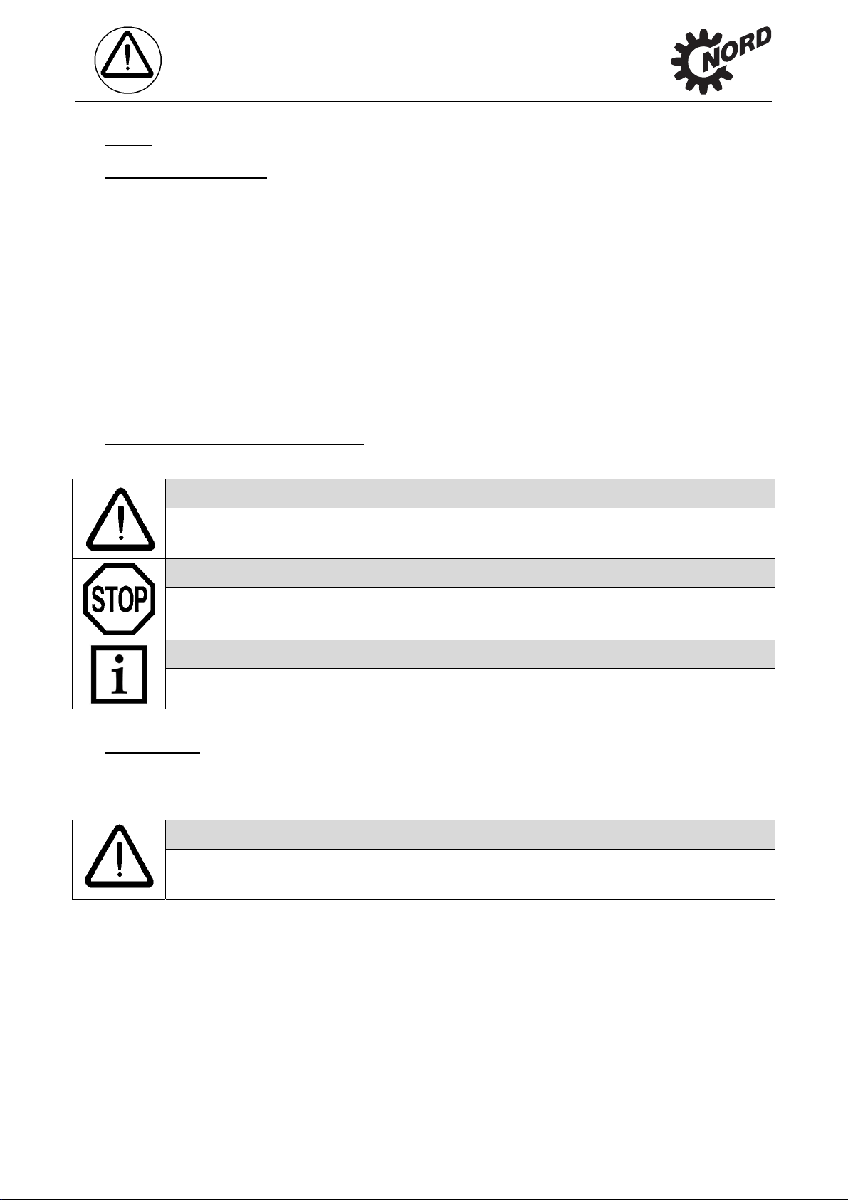
1.2 Safety and information symbols
Please always observe the following safety and information symbols!
Danger!
1. Notes
Risk of fatalities and injury
Attention!
Machine may be damaged
Note!
Useful information
1.3 Correct use
These gear units generate a rotational movement and are intended for use in commercial
systems. The gear unit must only be used according to the information in the technical
documentation from Getriebebau NORD.
Danger!
Use in explosion hazard areas is prohibited.
Strict compliance with the technical data on the rating plate is essential.
The documentation must be observed.
Appropriate safety measures must be taken for applications where failure of a gear unit or
geared motor may result in injury.
-4- B1050-GB-0213 www.nord.com
Page 4

1.4 Safety information
All work including transportation, storage, installation, electrical connection, commissioning,
servicing, maintenance and repair must be performed only by qualified specialist personnel.
It is recommended that repairs to NORD Products are carried out by the NORD Service
department.
Danger!
Installation and maintenance work must only be performed when gear units are at a standstill
and have cooled down. The drive must be isolated and secured to prevent accidental start-up.
Tighten the drive elements or secure the parallel key before switching on.
Observe all safety information, including that provided in the individual sections of this
Operating Manual. All national and other regulations on safety and accident prevention must
also be observed.
Danger!
Serious physical and property damage may result from inappropriate installation, non-
designated use, incorrect operation, non-compliance with safety information, unauthorised
removal of housing components or safety covers and structural modifications to the gear unit.
All rotating components must be provided with guards. In standard cases, covers are fitted by
NORD . The covers must always be used if contact protection is not provided by other methods.
1. Notes
1.5 Other documents
Further information may be obtained from the following documents:
- Gear Unit Catalogue (G1050)
- Operating and maintenance instructions for the electric motor
- If applicable, operating instructions for attached or supplied options
1.6 Disposal
Observe the current local regulations. In particular, lubricants must be collected and dispose d of
correctly.
Gear unit components: Material:
Toothed wheels, shafts, rolling bearings,
parallel keys, locking rings, …
Gear unit housing, housing components, … Grey cast iron
Light alloy gear unit housing, light alloy gear unit
housing components, …
Worm gears, bushes, ... Bronze
Radial seals, sealing caps, rubber components,… Elastomers with steel
Coupling components Plastic with steel
Flat seals Asbestos-free sealing material
Gear oil Additive mineral oil
Synthetic gear oil (rating plate code: CLP PG) Polyglycol-based lubricants
Cooling spiral, screw fittings Copper, epoxy, yellow brass
Steel
Aluminium
www.nord.com B1050-GB-0213 -5-
Page 5
V
2. Description of Gear Unit
2. Description of gear units
2.1 Type designations and gear unit types
Helical gear units
SK 7207, SK 8207, SK 9207, SK 10207
SK 11207, SK 12207, SK 13207, SK 15207
(2-stage)
SK 7307, SK 8307, SK 9307, SK 10307
SK 11307, SK 12307, SK 13307, SK 15307
(3-stage)
Bevel helical gear units
SK 7407, SK 8407, SK 9407, SK 10407
SK 11407, SK 12407, SK 13407, SK 15407
(3-stage)
SK 7507, SK 8507, SK 9507, SK 10507
SK 11507, SK 12507, SK 13507, SK 15507
(4-stage)
ersions / Options
- Foot mounting with solid shaft
A Hollow shaft version
B Fixing element
CC Integrated cooling coil
CS1 Cooling system oil / water
CS2 Cooling system oil / air
D Torque support
EA Hollow shaft with internal spline
ED Elastic torque support
EV Solid shaft with internal spline
EW Drive shaft with internal spline
F Block flange
FAN Fan
FK Collar flange
F1 Drive flange
H Covering cap as contact guard
IEC Standard IEC motor attachment
L Solid shaft both sides
LC Lubricant circulation
MC Motor bracket
MF.. Motor base frame
…B with brake
…K with elastic coupling
…T with hydrodynamic coupling
MS.. Motor swing base
…B with brake
…K with elastic coupling
…T with hydrodynamic coupling
MT Motor mount
NEMA Standard NEMA motor attachment
OA Oil expansion vessel
OH Oil heater
OT Oil level tank
R Back stop
S Shrink disc
V Solid shaft
VL Reinforced bearings
VL2 Agitator version
VL3 Drywell agitator version
W Free input shaft
W2 Two drive shaft journals
W3 Three drive shaft journals
WX Auxiliary drive unit
Double gear units consist of two single gear units. They are to be treated as per the instructions
in this Manual, i.e. as two individual gear units. Type designation of double gear units:
e.g. SK 13307/7282 (consisting of single gears SK 13307 and SK 7282)
-6- B1050-GB-0213 www.nord.com
Page 6
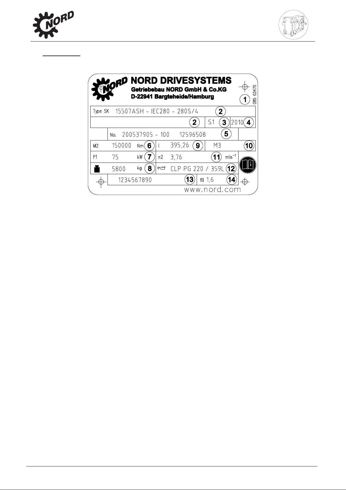
2.2 Name plate
Example of a gear unit name plate.
2. Description of Gear Unit
Explanation of the name plate
1 Matrix – Barcode
2 NORD gear unit type
3 Operating mode
4 Year of manufacture
5 Serial number
6 Rated torque of gear unit output shaft
7 Drive power
8 Weight according to ordered version
9 Overall gear unit ratio
10 Installation orientation
11 Rated speed of gear unit output shaft
12 Lubricant type, viscosity and quantity
13 Customer’s part number
14 Operating factor
www.nord.com B1050-GB-0213 -7-
Page 7

3. Storage, Transport,
3. Storage, transport, preparation, installation
Please observe all of the general safety information in Section 1.4, 1.3 and in the individual
sections.
3.1 Storing the gear unit
For short-term storage before commissioning, please observe the following:
Store in the fitting position (see Section 6.1) and secure gear units against falling
Lightly grease bare metal housing surfaces and shafts
Store in dry rooms
Temperature in the range from –5
Relative humidity less than 60%
No direct exposure to sunlight or UV light
No aggressive, corrosive substances (contaminated air, ozone, gases, solvents, acids,
alkalis, salts, radioactivity etc.) in the immediate vicinity
No vibration or oscillation
3.2 Long-term storage
Preparation, Installation
o
C to +50 oC without large fluctuations
Note!
For storage or standstill periods in excess of 9 months, Getriebebau NORD recommends the
long-term storage option. With the long-term storage option and the use of the measures
listed below, storage for up to 2 years is possible. As the actual influences on the unit greatly
depend on the local conditions, these times should only be regarded as guide values.
Conditions of the gear unit and storage area for long-term storage prior to
commissioning:
Store in the fitting position (see Section 6.1) and secure gear units against falling
Transportation damage to the external paint must be repaired. Check that a suitable rust
inhibitor is applied to the flange bearing surfaces. If necessary apply a suitable rust inhibitor
to the surfaces.
Gear units with the long-term storage option are completely filled with lubricant or have VCI
corrosion protection agents added to the gear oil. (See label on gear unit)
The sealing band in the vent plug must not be removed during storage. The gear unit must
remain sealed tight.
Store in a dry place.
In tropical regions, the drive unit must be protected against damage by insects
o
Temperature in the range from –5
Relative humidity less than 60%
No direct exposure to sunlight or UV light
No aggressive, corrosive substances (contaminated air, ozone, gases, solvents, acids,
alkalis, salts, radioactivity etc.) in the immediate vicinity
No vibration or oscillation
C to +40 oC without large fluctuations
Measures during storage or standstill periods
If the relative humidity is <50% the gear unit can be stored for up to 3 years.
Measures before commissioning
If the storage or standstill period exceeds 2 years or the temperature during short-term
storage greatly deviates from the standard range, the lubricant in the gear unit must be
replaced before commissioning.
If the gear unit is completely filled, the oil level must be reduced before commissioning.
-8- B1050-GB-0213 www.nord.com
Page 8
3.Storage, Transport,
Preparation, Installation
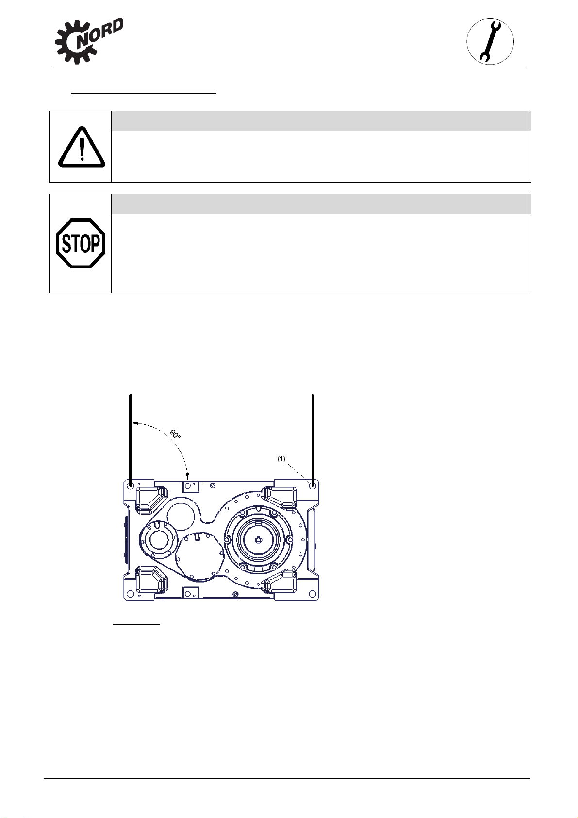
3.3 Transporting the gear unit
Danger!
To prevent injury, the danger area must be generously cordoned off. Standing under the
gear unit during transport is extremely dangerous.
Attention!
Avoid damage to the gear unit. Impacts to the free ends of the shafts may cause internal
damage to the gear unit.
Use adequately dimensioned and suitable means of transportation. Lifting tackle must be
designed for the weight of the gear unit. The weight of the gear unit can be obtained from the
dispatch documents.
The gear unit should remain on the transport packaging during transportation. It must be
transported without oil. Only the f our ring bolts (1) provided may be used for transporting the
gear unit. For additional drive units and components, an additional lifting point may be
necessary. The ends of the shafts must not be used for transportation, as this may seriously
damage the gear unit. The ring bolts screwed into the gear unit must be used for transportation.
If geared motors have an additional eyebolt attached to the motor, this must not be used. When
lifting with the ring bolts, there must be no oblique force.
Figure 3-1: Gear unit lifting points
For additional drive units and components, an additional lifting point may be necessary.
www.nord.com B1050-GB-0213 -9-
Page 9
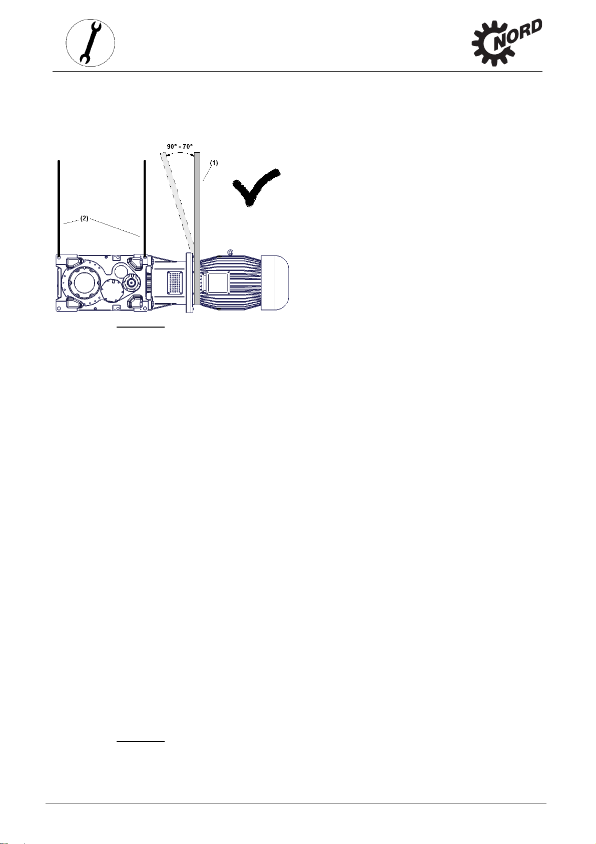
Gear units with motor adapter
Gear units with a motor adapter may only be transported with lifting ropes (2) and chains or
lifting straps (1) at an angle of 90° to 70° to the horizontal. The ring bolts on the motor must not
be used for transportation.
3. Storage, Transport,
Preparation, Installation
Figure 3-2: Transport of gear unit with motor
Drive units with V-belt drive
Gear units with V-belt drive must only be transported with lifting straps (1) and lifting ropes (2) at
an angle of 90° (vertical). The ring bolts on the motor must not be used for transportation.
Figure 3-3: Transport of gear unit with V-belt drive
-10- B1050-GB-0213 www.nord.com
Page 10

3.Storage, Transport,
Gear units on motor swing base or base frame
Gear units on a motor swing base or base frame must only be transported with vertically
tensioned lifting ropes (1) or chains.
Preparation, Installation
Figure 3-4: Transport of gear unit with motor swing base or base frame
www.nord.com B1050-GB-0213 -11-
Page 11

3.4 Preparing for installation
The drive unit must be inspected and may only be installed if no damage is apparent. In
particular the radial seals and the sealing caps must be inspected for damage.
All bare metal surfaces and shafts of the gear unit are protected against corrosion with oil,
grease or corrosion protection agents before shipping.
Thoroughly remove all oil, grease or corrosion protection agents and any dirt from the shafts and
flange surfaces before assembly.
In applications where an incorrect rotational direction may result in damage or potential risk, the
correct rotational direction of the drive shaft is to be established by test running the drive when
uncoupled and guaranteeing such for subsequent operation.
Gears with integrated return stops are marked with arrows on the driven/driving sides. The
arrows point in the rotation direction of the gear unit. It must be ensured, when connecting the
motor and during motor control, that the gear unit can only operate in the rotation direction, e.g.
by means of a rotary field test.
Attention!
With gear units with an integrated back stop, switching the drive motor to the blocked rotation
direction, i.e. incorrect rotation direction, can lead to gear damage.
Ensure that no aggressive or corrosive substances are present in the area surrounding the
installation site or are subsequently expected during operation, which attack metal, lubricants or
elastomers. In case of doubt, please contact Getriebebau NORD and take the recommended
action.
Oil expansion tanks (Option OA) must be fitted in accordance with the attached works standard
WN 0-530 04.
Oil expansion tanks (Option OA) must be fitted in accordance with the attached works standard
WN 0-521 30.
3. Storage, Transport,
Preparation, Installation
3.5 Installing the gear unit
The base or flange to which the gear unit is fitted should be vibration-free, torsionally rigid and
flat. The smoothness of the mating surface on the base or flange must be according to tolerance
class K of DIN ISO 2768-2. All contamination to the bolting surfaces of gear unit and base or
flange must be thoroughly removed.
The base must be designed according to the weight and torque, taking into account the forces
acting on the gear unit. Bases which are insufficiently rigid may lead to radial and axial
displacement during operation, which is not measurable when the unit is stopped.
When attaching the gear unit to a concrete base using masonry bolts or base blocks, appropriate
recesses must be provided in the base. Tensioning bars must be cast into the concrete base in
their aligned state.
The gear unit must be precisely aligned with the drive shaft of the machine in order to prevent
additional forces from being imposed on the gear unit due to distortion.
Note!
The service life of shafts, bearings and couplings depends on the precision of alignment of the
shaft. Therefore, zero deviation should always be aimed for in alignment. For this, e.g. the
requirements for the coupling should be obtained from the special o perating instructions.
The tolerances of the shaft ends and the flange connections should be obtained from the
dimension sheet.
-12- B1050-GB-0213 www.nord.com
Page 12

3.Storage, Transport,
Welding of the gear unit is prohibited. The gear unit must not be used as the earth connection for
welding work, as this may cause damage to the bearings and gear wheels.
The gear unit must be installed in the correct orientation (see Section 6.1). All gear unit feet
on each side or all flange screws must be used. Bolts must have a minimum quality of 8.8. The
bolts must be tightened to the correct torques (refer to Section 6.4 for torque values). Tensionfree bolting must be ensured, particularly for gear units with a foot and flange.
Preparation, Installation
Danger!
To ensure that the gearbox does not get too hot and to avoid injury to persons, observe
the following during installation:
The surfaces of gear units or geared motors may become hot during or shortly after
operation. Attention: danger of burns!! Protection against accidental contact may need to
be installed.
With geared motors, the cooling air of the motor fan must be able to flow unobstructed
onto the gear unit.
3.6 Fitting hubs on the gear shafts
Attention!
Do not subject the gear unit to harmful axial forces when fitting the hubs.
Drive and driven elements, e.g. coupling and chain-wheel hubs must be mounted onto the drive
and driven shaft of the gear unit using suitable pullers that will not apply damaging axial forces
onto the gear unit. In particular, do not hit the hubs with a hammer.
Use the end thread of the shafts for pulling. Fitting can be aided by coating the hub with lubricant
or heating it up to approx. 100
Figure 3-5: Example of a simple pulling device
o
C beforehand.
Danger!
Drive and driven elements, such as belt drives, chain drives and couplings must be fitted
with contact protection.
Drive and driven elements may only subject the drive unit to the maximum radial forces
and axial forces FA specified in the catalogue. Observe the correct tension, particularly on
belts and chains. Additional loads due to unbalanced hubs are not permitted. The radial force
must be applied to the gear unit as closely as possible.
www.nord.com B1050-GB-0213 -13-
Page 13

3.7 Fitting push-on gear units
Achtung!
The bearings, gear wheels, shafts and housing may be damag ed by incorrect fitting.
The push-on gear unit must be fitted onto the shaft using a suitable puller, which will not exert
damaging axial forces on the gear unit. In particular, do not hit the gear unit with a hammer.
Assembly and subsequent dismantling is aided by applying an anti-corrosive lubricant to the
shaft before fitting.
Figure 3-6: Applying lubricant to the shaft and the hub
3. Storage, Transport,
Preparation, Installation
Note!
The gear unit can be fitted to shafts with and without a shoulder using the fastening element
(Option B). Tighten the bolt of the fastening element to the correct torque. (See Chapter 6.4 for
tightening torque values)
Figure 3-7: Assembly
-14- B1050-GB-0213 www.nord.com
Page 14

3.Storage, Transport,
Preparation, Installation
Figure 3-8: Securing
Figure 3-9: Dismantling
1 Fastening element
2 Securing ring
3 Assembly – threaded rod
4 Assembly – threaded nut
6 Protective cover
7 Disassembly of threaded rod
8 Disassembly element
9 Disassembly – threaded nut
When assembling push-on gears with torque supports, the support must not be distorted.
Distortion-free assembly is made easier if an elastic element (Option DG) is used.
www.nord.com B1050-GB-0213 -15-
Page 15

3.8 Torque support
The length of the torque support can be adjusted within a certain range. The torque support
consists of a fork head with a bolt (1), a threaded bolt (2), a maintenance-free joint head (3) and
a fork plate with a bolt (4).
Assembly should be carried out from the side of the machine, in order to reduce the bending
moment on the machine shaft. Tension and pressure and installation upwards or downwards are
not permissible.
Distortion of the torque support during assembly or operation must be avoided, as otherwise the
service life of the output shaft bearings may be reduced. Torque supports are not suitable for the
transfer of radial forces, therefore they may only be used in combination with motor mounts or
couplings which do not transfer radial forces.
For helical gear units with motor mounts, the torque support is located opposite to the motor
mount.
The gear unit is aligned horizontally with the threaded bolt and the nuts of the torque support
and must be secured with lock-nuts.
3. Storage, Transport,
Preparation, Installation
3.9 Fitting shrink discs
Attention!
The operating instructions for the shrink disc must be observed.
Figure 3-10: Permissible installation deviations of the torque support
-16- B1050-GB-0213 www.nord.com
Page 16

3.Storage, Transport,
Preparation, Installation
3.10 Fitting the covers
Danger!
Shrink discs and exposed rotating shaft ends require contact guards in order to prevent
injuries. A cover (Option H) can be used as a guard. If this does not achieve sufficient
protection against contact according to the required protection type, the machinery and plant
constructor must ensure this be means of special attached components.
All fixing screws must be used and tightened to the correct torque. (See Chapter 6.4 for torque
values)
3.11 Fitting a standard motor
The maximum permitted motor weights indicated in the table below must not be exceeded when
attaching the motor to an IEC- / NEMA adapter:
IEC motor size
63 71 80 90 100 112 132
Maximum permitted motor weights
NEMA motor
size
max. Maximum
motor weight
[kg]
IEC motor size
NEMA motor
size
max. Maximum
motor weight
[kg]
Transnorm
max. Maximum
motor weight
[kg]
56C 143T 145T 182T 184T 210T
25 30 40 50 60 80 100
160 180 200 225 250 280 315
250T 280T 324T 326T 365T
200 250 350 500 700 1000 1500
315 355 400 450
1500 2200 3200 4400
www.nord.com B1050-GB-0213 -17-
Page 17

3. Storage, Transport,
Assembly procedure to attach a standard motor to the IEC adapter (Option IEC)/NEMA adapter
1. Clean motor shaft and flange surfaces of motor and adapter and check for damage.
Mounting dimensions and tolerances of the motor must conform to DIN EN 50347/NEMA
MG1 Part 4.
2. Push the coupling sleeve onto the motor shaft so that the motor parallel key engages into
the groove in the sleeve on tightening.
3. Pull the coupling sleeve onto the motor shaft according to the instructions of the motor
manufacturer. The shaft end of the motor must be adjusted so that it is parallel with the face
of the coupling. (See Figure 3-11)
4. Secure the coupling half with the threaded pin. The threaded pin must be coated prior to use
with a securing lubricant e.g. Loctite 242, Loxeal 54-03 and tightened to the correct torque.
(See Chapter 6.4 for torque values)
5. Sealing of the flange surfaces of the motor and the adapter is recommended if the motor is
installed outdoors or in a humid environment. The flange surfaces of motor and adapter
must be completely coated with surface sealant Loctite 574 or Loxeal 58-14 prior to
mounting so that the flange seals after mounting.
6. Mount the motor to the adapter; do not forget to fit the gear rim or the sleeve.
7. Tighten the adapter bolts to the correct torque. (See Chapter 6.4 for torque values)
Preparation, Installation
Figure 3-11: Fitting the coupling to the motor shaft
Attention!
The operating instructions for the coupling must be observed.
-18- B1050-GB-0213 www.nord.com
Page 18

3.Storage, Transport,
Preparation, Installation
3.12 Fitting the cooling coil to the cooling system
For the inlet and outlet of cooling fluid, connections with G ½ pipe thread are located in the
casing cover for the fitting of pipes or hoses. Remove the drain plug from the screw
connectors prior to assembly to avoid any contamination of the cooling system. The
screw connectors should be connected with the coolant circuit, which must be provided by the
operator. The flow direction of the coolant is irrelevant.
Attention!
Make sure not to twist the screw connectors during or after assembly as this may
damage the cooling coil (see Item 3, Fig. 3-12). Ensure that no external forces act on the
cooling coil.
If a volume regulator is fitted upstream of the cooling coil, the connection is extended
accordingly. The cooling water must be inlet via the volume regulator. Observe the operating
instructions of the volume regulator.
Figure 3-12: Cooling cover with cooling coil fitted
3.13 Mounting the external cooling system (cooling unit)
Attention!
The separate manufacturer’s documentation must be observed for assembly.
Connect the cooling system according to Fig. 3-14. Other connection plans can be agreed upon
during consultation with NORD.
Pos.3
www.nord.com B1050-GB-0213 -19-
Page 19

3. Storage, Transport,
(5)
)
Attention!
With circulation lubrication (LC) use the connection diagram included by NORD.
Preparation, Installation
Figure 3-13: Industrial gear unit with CS1 and CS2 cooling systems
Figure 3-14: Hydraulic diagram of the industrial gear unit with CS1 and CS2 cooling systems
3.14 Retrospective paintwork
(1) Gear unit intake connection
(2) Pump / cooling system intake connection
(3) Cooling system pressure connection
(4) Gear unit pressure connection
Temperature monitoring (optional
Attention!
For retrospective painting of the gear unit, the radial seals, rubber elements, pressure venting
valves, hoses, type plates, adhesive labels and motor coupling components must not come
into contact with paints, lacquers or solvents, as otherwise components may be damaged or
made illegible.
-20- B1050-GB-0213 www.nord.com
Page 20

4. Commissioning
4. Commissioning
4.1 Checking the oil level
The oil level must be checked prior to commissioning. See Section 5.2.
4.2 Lubricant cooling with internal water cooler
Caution!
The drive may only be commissioned after the cooling coil has been connected to the cooling
circuit, and the cooling circuit has been put into operation.
The coolant must have a similar thermal capacity as water (specific thermal capacity at 20°C
c=4.18 kJ/kgK). Industrial water without any air bubbles or sediments is recommended as a
coolant. The water hardness must be between 1° dH and 15° dH, and the pH value must be
between pH 7.4 and pH 9.5. No aggressive liquids should be added to the coolant!
The coolant pressure must not exceed 8 bar. The required quantity of coolant is 10
litres/minute, and the coolant inlet temperature should not exceed 40°C; we recommend
10°C.
We also recommend fitting a pressure reducer at the coolant inlet to avoid any damage due to
excessive pressure.
If there is a danger of frost the operator should add a suitable anti-freeze solution to the cooling
water.
The temperature of the cooling water and the cooling water flow rate must be supervised
and ensured by the operator.
Note!
With a thermostat in the cooling water inlet, the volume of cooling water can be adjusted to
the actual requirements.
4.3 Lubricant cooling with external oil/water cooler (cooling system)
Attention!
The operating instructions for the cooling system must be observed.
The oil / water cooler consists of at least a motor pump, a filter and a flat plate heat exchanger. In
addition, a pressure switch is usual in order to monitor the pump and therefore the lubrication.
Caution!
The drive unit may only be put into operation after the cooling coil has been connected and
put into operation.
www.nord.com B1050-GB-0213 -21-
Page 21

4. Commissioning
Caution!
The cooling system filter must be checked regularly and replaced if the contamination
indicator triggers.
Note!
With a thermostat in the cooling water inlet, the volume of cooling water can be adjusted to
the actual requirements.
4.4 Lubricant cooling with external oil/water cooler (cooling system)
Attention!
The operating instructions for the cooling system must be observed.
Caution!
The drive unit may only be put into operation after the cooling coil has been connected and
put into operation.
Caution!
The cooling system filter must be checked regularly and replaced if the contamination
indicator triggers.
Caution!
An adequate air intake must be ensured. The air inlet grille and the fan blades must be kept
clean.
Temperature regulation is provided by means of a thermostat, which is installed in the oil sump
of the gear unit.
4.5 Gear unit cooling with a fan
Caution!
An adequate air intake must be ensured. The air inlet grille and the fan blades must be kept
clean.
Danger!
Fans require guards in order to prevent injuries. A cover can be used as a guard. If this
does not achieve sufficient protection against contact according to the required protection type,
the machinery and plant constructor must ensure this be means of special attached
components.
-22- B1050-GB-0213 www.nord.com
Page 22

Caution!
The contact guard must be inspected for damage (e.g. due to incorrect transportation) as
contact with the fan may overload the gear unit.
4.6 Checking the Taconite seals
If Taconite seals are installed, check whether there is a gap between the bearing cover plates
(Pos. 1 and Pos. 2), and that this is filled with grease. Relubrication is carried out via the conical
grease nipple M10x1 - DIN 71412 (Pos.3).
Pos.1
4. Commissioning
Grease-filled gap
Pos.3
Figure 4-1: Testing a Taconite seal
4.7 Pressure safeguard
The pressure safeguard is an electric switch, which monitors the lubrication pressure of gear
units with circulation lubrication or targeted lubrication. If the pre-set pressure is undershot, the
applied electric signal is interrupted by the pressure safeguard. Evaluate the signal accordingly.
Caution!
Connect the pressure safeguard so as to be fully functional before starting operation for the
first time. The pressure safeguard can only be used in combination with a monitoring system.
Note!
Pos.2
Evaluate the pressure safeguard after initially operating the pump, as pressure must be built
up.
www.nord.com B1050-GB-0213 -23-
Page 23

4. Commissioning
4.8 Checklist
Checklist
Information –
Object of the check Checked on:
Is the vent screw screwed in? Sec. 3.3
Does the required configuration conform with the actual installation? Sec. 6.1
Are the external gear shaft forces within permitted limits (chain tension)? Sec. 3.5
Is the torque support correctly fitted? Sec. 3.6
Are contact guards fitted to rotating components? Sec. 3.8
Is the cooling system connected? Sec. 3.14/4.3
Is a grease-filled gap visible with Taconite seals? Sec. 4.5
Has the pressure safeguard been functionally connected? Sec. 4.7
see Section
-24- B1050-GB-0213 www.nord.com
Page 24

5. Service and Maintenance
5. Service and maintenance
5.1 Service and maintenance intervals
Service and Maintenance Intervals Service and Maintenance Work
Information –
see Section
At least every six months - Visual inspection
- Check for running noises
- Check oil level
- Regrease
- Check oil filter
- Check fans for dirt
- Re-lubricate the Taconite seals
For operating temperatures up to 80°C
Every 10000 operating hours, at least
every 2 years
(The interval is doubled if filled with
synthetic products)
For higher temperatures or extreme
operating conditions (high humidity,
aggressive environments and large
temperature fluctuations) the oil change
intervals must be halved.
At least every 10 years - General overhaul 5.2
- Change the oil
- Replace the oil filter
- Clean or replace the vent plug or the vent filter
5.2
5.2
5.2
5.2
5.2
5.2
5.2
5.2
5.2
5.2
5.2 Service and maintenance work
Servicing and maintenance work must only be performed by qualified specialist
personnel.
Installation and maintenance work must only be performed when gear units are at a
standstill. The drive must be isolated and secured to prevent accidental start-up.
Visual inspection:
The gear unit must be checked for leaks. In addition, the gear unit must be inspected for external
damage and cracks in the hoses, hose connections and rubber buffers. Have the gear unit
repaired in case of leaks, e.g. dripping gear oil or cooling water, damage or cracks. Please cont act
the NORD service department.
Check for running noises
If the gear unit produces unusual running noises and/or vibrations, this could indicate damage to
the gear unit In this case the gear should be shut down and a general overhaul carried out.
www.nord.com B1050-GB-0213 -25-
Page 25

Check the oil level
Section 6.1 describes the versions and the corresponding oil level screws. With double gear
units, the oil level must be checked on both units. The pressure vent must be at the position
marked in Section 6.1.
Gear unit types that are not supplied full of oil must be filled before the oil level is checked. (See
“Changing the oil”)
Checking the oil level:
1. The oil level may only be checked when the gear unit is at a standstill and has cooled
2. Gear units with oil level screw: The oil level screw corresponding to the version must be
3. Gear units with oil inspection glass or oil level glass: The oil level in the gear unit can be
4. Gear units with dipstick: The oil level in the gear unit must be between the upper and lower
6. Appendix
down. The gear unit must be secured to prevent accidental switch-on.
screwed out. (See Section 6.1) The oil level in the gear unit must be checked and corrected
with the correct type of oil if necessary. The correct oil level is the middle of the inspection
glass.
seen directly in the viewing window. Correct with the correct type of oil if necessary.
mark when the dipstick is completely screwed in (see Fig. 5-1). The oil level must be
corrected with the correct type of oil if necessary.
5. Gear units with an oil level vessel: The oil level must be checked in the oil level vessel with
the aid of the dipstick plug (thread G1 1/4). The oil level must be between the upper and
lower mark when the dipstick is completely screwed in (see Fig. 5-1). The oil level must be
corrected with the correct type of oil if necessary. These gearboxes may only be operated in
the configuration stated in Section 6.1.
6. The oil level screw or the cap screw with dipstick and all other loosened screws must be
correctly re-tightened.
Regreasing
Some gear unit designs (agitator designs VLII and VLIII) are equipped with a regreasing device.
Via the grease nipple, the external roller bearing is regreased with approx. 20-25g of grease.
Recommended grease: Petamo GHY 133N (see Section 6.2: Klüber Lubrication).
Checking the oil filter
The oil filters are quipped with a visual or electro-mechanical contamination indicator. If
contamination is indicated, the oil filter must be replaced according to the operating instructions
for the particular cooling system.
Figure 5-1: Checking the oil level with a dipstick
-26- B1050-GB-0213 www.nord.com
Page 26

Re-lubricating the Taconite seals
The grease nipples of the Taconite seals must be filled with grease until clean grease emerges
from the grease gap. Remove and dispose of escaping grease. Recommended grease: Petamo
GHY 133N (see Section 6.2: Klüber Lubrication).
Note!
Optimal re-lubrication is achieved by rotating the gear unit shaft in 45° steps when lubricating
and pressing in grease until clean grease emerges from the shaft.
Checking fans for dirt
The inlet and outlet openings on the fan cover and the fan wheel must be kept clean.
Danger!
High pressure washers and compressed air must not be used for cleaning, as particles
or water may enter the gear unit.
5. Service and Maintenance
Danger!
Before recommissioning, observe the notes in Section 4.4.
Changing the oil
The figures in Section 6.1 show the oil drain screw, the oil level screw and the pressure vent
screw for various designs.
Procedure:
1. Place a catchment vessel under the oil drain screw or the oil drain cock.
2. Completely remove oil level screw, screwed sealing plug with dipstick if an oil level tank
Danger!
Warning: Hot oil!
3. Drain all the oil from the gear unit.
4. If the screw lock coating of the oil drain screw or oil level screw is damaged in the
5. Support the seal ring, insert the oil drain screw into the hole and tighten to the correct
6. Using a suitable filling device, refill with oil of the same type through the oil level hole
is being used and oil drain screw.
thread, a new oil level screw must be used or the thread cleaned and coated with
securing lubricant, e.g. Loctite 242, Loxeal 54-03 prior to inserting. The seal ring must be
replaced if damaged.
torque! (See Chapter 6.4 for torque values)
until oil emerges from the oil level hole. (The oil can also be filled through the pressure
vent screw or a sealing plug located higher than the oil level). If an oil level vessel is
used, fill the oil through the upper inlet (thread G1¼) until the oil level is set as described
in Section 5.2.
www.nord.com B1050-GB-0213 -27-
Page 27

7. Wait at least 15 minutes, or at least 30 minutes if an oil level tank is used, and then
check the oil level. Proceed as described in Section 5.2.
Replacing the oil filter
The oil filter must be changed according to the operating instructions from the supplier.
Cleaning or replacing the vent plug or the vent filter
In case of heavy soiling, unscrew the vent plug or vent filter and clean it thoroughly or fit a new
vent plug or vent filter with a new sealing ring.
General overhaul
The gear unit must be completely dismantled. The following work must be carried out:
Clean all gear unit components
Examine all gear unit components for damage
All damaged components must be replaced
All roller bearings must be replaced
6. Appendix
Replace back stops if fitted
Replace all seals, radial seals and Nilos rings
Replace plastic and elastomer components of the motor coupling
The general overhaul must be carried out by qualified personnel in a specialist workshop with
appropriate equipment in observance of national regulations and laws. We recommend that the
general overhaul is carried out by the NORD Service department.
-28- B1050-GB-0213 www.nord.com
Page 28

6. Appendix
6.1 Versions and maintenance
Note!
The version and the position of the oil drain, vent and oil level should be primarily
obtained from the dimension sheet. If this does not contain any details, the following
details can be used.
6. Appendix
4
(both sides)
3
(both sides)
(according to assembly)
7
6
(6)
(according to assembly)
Figure 6-1: Position of the oil screws in the gear unit
Installation orientation
No. Thread M1 M2 M3 M4 M5 M6
1)
S
1 G1 A
2 G1
E S
3 G1 E
4 G1
5 G1
6 G1
7 G1
E --- E S S
--- --- --- --- --- ---
2)
A / E
1)
S
E S1) A S1) S1)
8 G1 S
1)
S
9 G1
10 G1
A S E E A
A E E A S
E S1) A / E A / E
1)
A S1) A / E A / E
S E S
1)
S S1)
1)
S
A / E2) A S1) S1)
A S
1)
E A E
1)
S1)
(both sides)
1
2
(both sides)
9
Oil drain
A
Vent
E
Oil level screw
S
Closed
G
1)
Special oil level
According to cover
2)
assembly
8
10
Legend
www.nord.com B1050-GB-0213 -29-
Page 29

6. Appendix
Installation orientations for helical gear units
M6
Drive at top
(vertical)
M4
Output at bottom
(standing)
Standard installation, 2-stage
M1
(horizontal)
M2
Output at top
(standing)
M5
Output at bottom
(vertical)
Standard installation,
3-stage (horizontal)
Installation orientations for bevel helical gear units
M6
Drive at top
(vertical)
M4
Output at bottom
(standing)
M3
M1
Standard installation, 2-stage
(horizontal)
M2
Output at top
(standing)
M5
Output at bottom
(vertical)
Standard installation,
3-stage (horizontal)
-30- B1050-GB-0213 www.nord.com
M3
Page 30

6.2 Lubricant quantities
Note!
After changing the lubricant, and in particular after the initial filling, the oil level may change
during the first few hours of operation, as the oil galleries and hollow spaces only fill gradually
during operation. The oil level is still within the permissible tolerance.
If at the express request of the customer, an oil inspection glass is installed at an additional
charge, we recommend that the customer corrects the oil level after an operating period of
approx. 2 hours, so that when the gear unit is at a standstill and has cooled down, the oil level
is visible in the inspection glass. Only then, is it possible to check the oil level by means of the
inspection glass.
Note!
The stated filling quantities are guide values. The exact quantities vary according to the exact
gear ratio. When filling, the precise quantity must be observed on the oil level indicator.
Note!
6. Appendix
The values in brackets apply for circulation lubrication.
Helical gear units
[L] M1 M2 M3 M4 M5 2) M6 2) max 3)
SK 7207 36 45 36 48 46 46 62
SK 7307 36 45 36 48 46 46 62
SK 8207 44 55 44 59 57 57 76
SK 8307 44 55 44 59 57 57 76
SK 9207 57 71 57 76 74 74 98
SK 9307 57 71 57 76 74 74 98
SK 10207 72 89 72 96 92 92 123
SK 10307 72 89 72 96 92 92 123
SK 11207 105 130 ( 50 ) 105 140 ( 40 ) 135 ( 45 ) 135 ( 45 ) 180
SK 11307 105 130 ( 50 ) 105 140 ( 40 ) 135 ( 45 ) 135 ( 45 ) 180
SK 12207 116 185 ( 83 ) 116 203 ( 65 ) 199 ( 69 ) 199 ( 69 ) 268
SK 12307 116 185 ( 83 ) 116 203 ( 65 ) 199 ( 69 ) 199 ( 69 ) 268
www.nord.com B1050-GB-0213 -31-
Page 31

[L] M1 M2 M3 M4 M5 2) M6 2) max 3)
SK 13207 154 256 ( 107 ) 154 290 ( 73 ) 268 ( 95 ) 268 ( 95 ) 363
SK 13307 154 256 ( 107 ) 154 290 ( 73 ) 268 ( 95 ) 268 ( 95 ) 363
SK 15207 358 415 ( 160 ) 335 450 ( 125 ) 405 ( 170 ) 412 ( 163 ) 575
SK 15307 358 415 ( 160 ) 335 450 ( 125 ) 405 ( 170 ) 412 ( 163 ) 575
Bevel helical gear units
6. Appendix
[L] M1 M2 M3 M4 1) M5 2) M6 2) max 3)
SK 7407 38 47 38 50 49 49 64
SK 7507 38 47 38 50 49 49 64
SK 8407 47 58 47 62 60 60 79
SK 8507 47 58 47 62 60 60 79
SK 9407 61 75 61 80 78 78 102
SK 9507 61 75 61 80 78 78 102
SK 10407 77 94 77 10 97 97 128
SK 10507 77 94 77 10 97 97 128
SK 11407 112 137 ( 57 ) 112 147 ( 47 ) 142 ( 52 ) 147 ( 47 ) 187
SK 11507 112 137 ( 57 ) 112 147 ( 47 ) 142 ( 52 ) 147 ( 47 ) 187
SK 12407 126 195 ( 93 ) 126 213 ( 75 ) 209 ( 79 ) 209 ( 79 ) 278
SK 12507 126 195 ( 93 ) 126 213 ( 75 ) 209 ( 79 ) 209 ( 79 ) 278
SK 13407 168 270 ( 121 ) 168 304 ( 87 ) 282 ( 109 ) 282 ( 109 ) 377
SK 13507 168 270 ( 121 ) 168 304 ( 87 ) 282 ( 109 ) 282 ( 109 ) 377
SK 15407 382 439 ( 184 ) 359 474 ( 149 ) 429 ( 194 ) 436 ( 187 ) 599
SK 15507 382 439 ( 184 ) 359 474 ( 149 ) 429 ( 194 ) 436 ( 187 ) 599
-32- B1050-GB-0213 www.nord.com
Page 32

6.3 Lubricants
Roller bearing greases
Lubricant type Ambient
Mineral oilbased grease
Synthetic
grease
Biodegradable
grease
temperature
-30 … 60°C Energrease
-50 … 40°C - Optitemp LG 2 RENOLIT JP
-25 … 80°C Energrease
-25 … 40°C Biogrease
LS 2
Energrease
LS-EP 2
SY 2202
EP 2
6. Appendix
Longtime PD 2 RENOLIT
GP 2
RENOLIT
LZR 2 H
1619
Tribol 4747 RENOLIT
HLT 2
RENOLIT
LST 2
- PLANTOGEL
2 S
- Mobilux EP 2 Gadus S2
- - -
PETAMO
GHY 133 N
Klüberplex
BEM 41-132
Klüberbio
M 72-82
Mobiltemp
SHC 32
Mobil SHC
Grease 102
EAL
V100 2
Cassida
EPS2
Naturelle
Grease EP2
Foodstuffcompatible
grease
-25 … 40°C - Obeen UF 2 RENOLIT
G 7 FG 1
Klübersynth
UH1 14-151
Mobilgrease
FM 222
Cassida
RLS2
This table shows comparable roller bearing greases from various manufacturers. The
manufacturer can be changed for a given grease type. Getriebebau NORD must be contacted in
case of change of grease type or ambient temperature range, as otherwise no warranty for the
functionality of our gear units can be accepted.
www.nord.com B1050-GB-0213 -33-
Page 33

Lubricant type
Mineral oil
Synthetic oil
(Polyglycol)
Synthetic oil
(Hydrocarbon)
Bio-degradable
oil
Foodstuff-
compatible oil
6. Appendix
Lubricant table
This table shows comparable lubricants from various manufacturers. The manufacturer can be
changed within a particular viscosity or lubricant type. Getriebebau NORD must be co ntacted in
case of change of viscosity or lubricant type, as otherwise no warranty for the functionality of our
gearboxes can be accepted.
ISO VG
AGMA
CLP 220
AGMA 5EP
CLP 320
AGMA 6EP
CLP 680
AGMA 8EP
CLP PG 220
AGMA 5EP
CLP PG 320
AGMA 6EP
CLP PG 680
AGMA 8EP
CLP HC 220
AGMA 5EP
CLP HC 320
AGMA 6EP
CLP HC 680
AGMA 8EP
CLP E 220
AGMA 5EP
CLP E 320
AGMA 6EP
CLP E 680
AGMA 8EP
CLP PG H1 220
AGMA 5EP
Energol
GR-XP 220
Energol
GR-XP 320
Energol
GR-XP 680
Enersyn
SG-XP 220
Enersyn
SG-XP 320
Enersyn
SG-XP 680
Enersyn
EP-XF 220
Enersyn
EP-XF 320
-
-
-
- -
- Optileb GT 220 -
Alpha SP 220
Alpha MAX 220
Optigear BM 220
Tribol 1100 / 220
Alpha SP 320
Alpha MAX 320
Optigear BM 320
Tribol 1100 / 320
Alpha SP 680
Optigear BM 680
Tribol 1100 / 680
Tribol 1300 / 220
Tribol 1300 / 320
Tribol 1300 / 680
Optigear Synth X
220
Tribol 1710 / 220
Optigear Synth X
320
Tribol 1710 / 320
Optigear Synth X
680
Tribol BioTop
1418 / 220
Tribol BioTop
1418 / 320
Renolin CLP 220
Renolin CLP 220
Plus Gearmaster
CLP 220
Renolin CLP 320
Renolin CLP 320
Plus Gearmaster
CLP 320
Renolin CLP 680
Renolin CLP 680
Plus Gearmaster
CLP 680
Renolin PG 220
Gearmaster PGP
220
Renolin PG 320
Gearmaster PGP
320
Renolin PG 680
Gearmaster PGP
680
Renolin Unisyn
CLP 220
Gearmaster SYN
220
Renolin Unisyn
CLP 320
Gearmaster SYN
320
Renolin Unisyn
CLP 680
Gearmaster SYN
680
Plantogear 220
S Gearmaster
ECO 220
Plantogear 320
S Gearmaster
ECO 320
Plantogear 680
S Gearmaster
ECO 680
Klüberoil GEM 1
- 220 N
Klüberoil GEM 1
- 320 N
Klüberoil GEM 1
- 680 N
Klübersynth GH
6 - 220
Klübersynth GH
6 - 320
Klübersynth GH
6 - 680
Klübersynth
GEM 4 - 220N
Klübersynth
GEM 4 - 320N
Klübersynth
GEM 4 - 680N
Klübersynth
GEM 2 - 220
Klübersynth
GEM 2 - 320
Klübersynth UH1
6 - 220
Mobilgear 600
XP 220 Mobilgear
XMP 220
Mobilgear 600
XP 320 Mobilgear
XMP 320
Mobilgear 600
XP 680 Mobilgear
XMP 680
-
-
-
Mobil SHC 630
Mobil SHC 632
-
-
-
- - -
-
Shell Omala F
220
Shell Omala F
320
-
Shell Omala S4
WE 220
Shell Cassida
WG 220
Shell Omala S4
WE 320
Shell Cassida
WG 320
Shell Omala S4
WE 680
Shell Cassida
WG 680
Shell Omala S4
GX 220
Shell Omala S4
GX 320
Shell Omala S4
GX 680
Shell Naturelle
Gear Fluid EP
220
Shell Naturelle
Gear Fluid EP
320
Shell Cassida
WG 220
CLP PG H1 320
AGMA 6EP
CLP PG H1 680
AGMA 8EP
- Optileb GT 320 -
- Optileb GT 680 -
Klübersynth UH1
6 - 320
Klübersynth UH1
6 - 680
-
-
Shell Cassida
WG 320
Shell Cassida
WG 680
-34- B1050-GB-0213 www.nord.com
Page 34

6.4 Bolt torque values
6. Appendix
Bolt Torques [Nm]
Screw connections in the strength
Size
8.8 10.9 12.9
M4 3,2 5 6 - - M5 6,4 9 11 - - 2
M6 11 16 19 - - M8 27 39 46 5 - 10
M10 53 78 91 8 - 17
M12 92 135 155 27 - 40
M16 230 335 390 - - M20 460 660 770 - - M24 790 1150 1300 80 - M30 1600 2250 2650 170 - M36 2780 3910 4710 - - M42 4470 6290 7540 - - M48 6140 8640 16610 - - M56 9840 13850 24130 - - G ½ - - - - 20 G ¾ - - - - 20 -
G 1 - - - 20 20 -
classes
Cap screws
Pipe and hose
connections
Threaded pin on
coupling
G1¼ - - - 20 20 -
www.nord.com B1050-GB-0213 -35-
Page 35

6. Appendix
6.5 Troubleshooting
Gear unit malfunctions
Malfunction Possible cause Remedy
Unusual running noises,
vibrations
Oil escaping from gear unit or
motor
Oil escaping from
pressure vent
Gear unit becomes too hot
Shock when switching on,
vibrations
Drive shaft does not rotate
although motor is running
Pressure at the pressure
safeguard is too low
Oil too low or
bearing damage or
toothed wheel damage
Defective seal Consult NORD Service
Incorrect oil level or
incorrect, contaminated oil or
unfavourable operating conditions
Unfavourable installation
conditions or gear unit damage
Defective motor coupling or
loose gear unit mounting or
defective rubber element
Fracture in gear unit or
defective motor coupling or
shrink disc slippage
Pump is not delivering any oil or
leakage in the piping
Consult NORD Service
Oil change
Use oil expansion tank
(Option OA)
Consult NORD Service
Replace elastomer gear rim,
tighten motor and gear unit
fastening bolts, replace rubber
element
Consult NORD Service
Check the pump and the pipes
Attention!
Warning: shut down the gear unit immediately should any of the above faults occur!
-36- B1050-GB-0213 www.nord.com
Page 36

NORD Drivesystems | Global vor Ort
www.nord.com/locator
Headquarters:
Getriebebau NORD GmbH & Co. KG
Rudolf-Diesel-Straße 1
22941 Bargteheide, Germany
Fon +49 (0) 4532 / 289 - 0
Fax +49 (0) 4532 / 289 - 2253
info@nord.com, www.nord.com
Member of the NORD DRIVESYSTEMS GROUP
DRIVESYSTEMS
Mat.-Nr. 6052902/0213
 Loading...