

Norcold NX61, NX84, NXA64, NXA84, NX64XIM Service Manual
...
Service Manual
Gas / Electric Refrigerators
MODELS
NX61 / NX81
NX64 / NX84
NXA64 / NXA84
NX64XIM / NX84XIM
NXA64XIM / NXA84XIM
NX64.3 / NX84.3
NXA64.3 / NXA84.3
WARNING
!
DO NOT install this refrigerator in below deck marine applications. Do not
install this refrigerator in fi xed indoor cabin or other dwelling applications. This
refrigerator must use only NORCOLD designed and approved outside air intake
and exhaust ventilation for correct and safe operation. Any other ventilation
could cause lethal combustion exhaust fumes and/or explosive propane gas
fumes to be in the living area and/or below deck.
Questions?/Des questions?/¿Preguntas? 1-800-543-1219
© 2013 NORCOLD, INC. All rights reserved.
Publication No. 636104B (27.01.2015)
CONTENTS
Introduction ..................................................................................................4
About this Manual ...................................................................................4
Model Identification .................................................................................4
Information Label ....................................................................................4
Certification and Code Requirements .....................................................4
About Installation ....................................................................................4
Replacement Parts .................................................................................4
T echnical Assistance ...............................................................................4
Model Identifi cation .....................................................................................5
Cooling Unit Serial Number ....................................................................5
Safety Awareness ........................................................................................6
Safety Notice ...........................................................................................6
Attention Statements ...............................................................................6
Safety Statements ...................................................................................6
Specifi cations ..............................................................................................7
NX61 / NX81, NX64 / NX84, NXA64 / NXA84 ........................................7
Theory of Operation ....................................................................................8
Overview .................................................................................................8
Cooling Unit ............................................................................................8
Leveled Operation ...................................................................................8
Gradual Decrease in Cooling Efficiency .................................................8
Gas Absorption System .......................................................................... 9
Electronic Controls ................................................................................10
Manual AC Mode .................................................................................. 10
Manual LP Gas Mode ............................................................................11
Manual DC Mode (3-way models only) ..................................................11
Auto Mode .............................................................................................12
Theory of Operation -
Auto Modes .........................................................................................12
Background Operations ........................................................................13
Diagnostic Prechecks ................................................................................15
Fault Codes ............................................................................................... 16
NX61 / NX81 Fault Codes .....................................................................16
Solid Red Indicator Light ..............................................................16
Fault / Flash Pattern 1 AC Heater Error .........................................17
Fault / Flash Pattern 2 Service Error ..............................................17
Fault / Flash Pattern 3
Open High Limit ................................................................................17
Fault / Flash Pattern 4
AC Relay Error .................................................................................17
Fault / Flash Pattern 5
Flame On Should Not Be On ............................................................18
Fault / Flash Pattern 8
LOW DC (1) Error .............................................................................18
Fault / Flash Pattern 9 LOW DC (2) Error ......................................18
Thermistor Fault .............................................................................19
Door Fault .......................................................................................19
Blank Display ..................................................................................19
NX64 / NX84, NXA64 / NXA84 Fault Codes .........................................22
Diagnostic Mode - NX64 / NX84, NXA64 / NXA84 ....................................26
Screens and Diagnostic Segments Information ....................................27
Ventilation ..................................................................................................29
Roof Exhaust Venting ...........................................................................29
Air Intake Vent ....................................................................................... 29
Roof Exhaust Vent ................................................................................ 29
Baffles ...................................................................................................30
Vertical Enclosures ...............................................................................31
Double Sidewall Venting ....................................................................... 35
Double Side Wall Venting......................................................................36
LP Gas System .........................................................................................38
Pressure Requirements ........................................................................38
Testing for LP Gas Leaks ......................................................................38
Components ..........................................................................................39
Flame Appearance ................................................................................ 41
Burner Cleaning Procedure ..................................................................42
Gas Lockout ..........................................................................................44
Reset a Gas Lockout Condition - All Models ......................................... 44
NX61 / NX81, NX64 / NX84, NXA64 / NXA84 Gas Safety Valve Test: .44
Electrical Requirements and Components ................................................ 45
DC Voltage Requirements and Polarity ................................................45
DC Power Wiring Requirements ........................................................... 45
AC/DC Converter as Power Source ......................................................45
AC Power Requirements ......................................................................46
12VDC Ventilation Fan .......................................................................... 47
Low Ambient Heater (optional) .............................................................. 48
Cooling Unit ...............................................................................................48
Cooling System Monitoring ................................................................... 48
Troubleshooting Cooling Faults ............................................................49
Refrigerant Leakage .............................................................................49
Disposal of Cooling Unit ........................................................................49
Cooling System Diagnostic Flowchart ..................................................50
Electrical Requirements and Components ............................................52
Modes of Operation - NX61, NX81 ...........................................................54
Start Up: ................................................................................................54
Shut Down: ...........................................................................................54
Modes of Operation - NX64 / NX84, NXA64 / NXA84 ..............................55
Start Up: ................................................................................................55
2-way Model Mode Indicators ............................................................... 55
3-way Model Mode Indicators ............................................................... 55
Shut Down: ...........................................................................................56
NX64 / NX84, NXA64 / NXA84 Display Codes .........................................56
Ice Maker ...................................................................................................57
Wire Harness ........................................................................................57
Fill Tube ................................................................................................57
Water Valve ...........................................................................................57
Specifications ........................................................................................57
Ice Maker Troubleshooting Chart ..........................................................58
Replacing the Ice Maker .......................................................................58
Cycle Test .............................................................................................59
Water Fill Adjustment ............................................................................60
Low Ice Yield .........................................................................................60
Water Valve Operation Test .................................................................. 60
Water Valve Solenoid Resistance ......................................................... 60
Mold Heater Resistance Check ............................................................61
Checking Voltage at Motor Terminals ...................................................61
Winterizing the Ice Maker Water ...........................................................61
2
www.norcold.com/cda
Refrigerator Service ManualNX6 / NX8 / NXA Models
Table of Contents - cont’d.
Figures
Fig. 1 - Refrigerator Information Label Location .............................. 5
Fig. 2 - Cooling Unit Bar Code
Label Location. ...................................................................................5
Fig. 3 - Gas Absorption System ........................................................9
Fig. 4 - Flash Patterns ....................................................................16
Fig. 5A - Thermistor .......................................................................19
Fig. 5B - Thermistor in Ice ..............................................................19
Fig. 6 - NX61 / NX81, NX64 / NX84, NXA64 / NXA84 Continuous 12-
Volt ................................................................................................... 21
Fig. 7 - NX61 / NX81, NX64 / NX84, NXA64 / NXA84 Switched
12-Volts ............................................................................................ 21
Fig. 8 - NX64 / NX84, NXA64 / NXA84 Display Board ..................26
Fig. 9 - Diagnostic LEDs Segments Identification ..........................26
Fig. 10 - Roof Exhaust Venting Arrangement. ...............................29
Fig. 11 - Rear View–Roof Exhaust Venting ....................................30
Fig. 12 - Baffles Req. for Inboard Roof Exhaust Vent Installation...30
Fig. 13 - Vertical Enclosure Depth of 24 > 26 Inches ....................31
Fig. 14 - Vertical Enclosure Depth of 26 > Inches .........................32
Fig. 15 - Offset Vertical Enclosure Depth of 24 > 25 Inches .......... 33
Fig. 16 - Offset Vertical Enclosure Depth of 26 > Inches ............... 34
Fig. 17 - Double Side Wall Enclosure Depths of 24 > 26 Inches ...36
Fig. 18 - Double Side Wall Enclosure Depth of 26 > Inches .......... 37
Fig. 19 - LP Gas System Components ........................................... 38
Fig. 20 - Solenoid Gas Valve. .........................................................39
Fig. 21 - LP15 Orifice Assemblies ..................................................40
Fig. 22 - Burner ............................................................................... 40
Fig. 23 - Burner Tube ......................................................................40
Fig. 24 - Flue and Components ...................................................... 41
Fig. 25 - Flue Baffle ........................................................................41
Fig. 26 - Flame Appearance ........................................................... 41
Fig. 27 - Drip Cup and Burner Box Cover ....................................... 43
Fig. 28 - Burner and Components .................................................43
Fig. 29 - DC Heater ........................................................................45
Fig. 30 - AC and DC Heaters (3-way refrigerator) .......................... 46
Fig. 31 - Lamp/Thermistor Assembly. .............................................46
Fig. 32 - AC Heater. ........................................................................ 46
Fig. 33 - AC Power Cord. ................................................................47
Fig. 34 - Fan Mounted on Top of Absorber Coil. ............................. 47
Fig. 35 - Fan Thermostat. ............................................................... 47
Fig. 36 - Fan with Installed NORCOLD Fan Kit .............................. 48
Fig. 38 - Wiring Diagram and Pictorial-Low Ambient Heater .......... 48
Fig. 37 - NORCOLD Fan Kit Wiring Pictorial ................................. 48
Fig. 39 - Reset Pushbutton .............................................................48
Fig. 40 - Cooling System Diagnostics ............................................. 50
Fig. 41 - Wiring - NX61 / NX81, NX64 / NX84, NXA64 / NXA84 ....52
Fig. 42 - Wiring - NX61 / NX81, NX64 / NX84, NXA64 / NXA84 ....53
Fig. 43 - NX61, NX81 Display Board .............................................. 54
Fig. 44 - NX64 / NX84, NXA64 / NXA84 Display Board ................55
Fig. 45 - Ice Maker .......................................................................... 57
Fig. 46 - Ice Maker Mounting Hardware .........................................58
Fig. 47 -Test points L and N. ........................................................... 59
Fig. 48 - Test points T and H. ..........................................................59
Fig. 49 - Water Fill Adjustment Screw and Indicator. ......................59
Fig. 50 - Energize water valve through test points V and L ............ 60
Fig. 51 - Measure water valve solenoid resistance ........................60
Fig. 52 - Measure mold heater resistance ...................................... 61
Fig. 53 - Check voltage to motor ...................................................61
Fig. 54 - NX64IM / NX84XIM, NXA64IM / NXA84XIM – Ice Maker
Wired to Refrigerator AC Cord ..........................................................62
Fig. 55 - NX64IM / NX84XIM, NXA64IM / NXA84XIM – Ice Maker
Wired to Unit Refrigerator Cord ........................................................ 62
Tables
Table 1: Temperature Set Points NX61 / NX81 ....................................14
Table 2: Temperature Set Points NX64 / NX84, NXA64 / NXA84.......................14
Table 3: Clearances for Roof Vented Installations ................................ 30
Table 4: NX61, NX81 Operation Modes ................................................54
Table 5: NX64 / NX84, NXA64 / NXA84 Operation Modes ................... 55
Table 6: NX64 / NX84, NXA64 / NXA84 Display Codes .......................56
www.norcold.com/cda
NX6 / NX8 / NXA ModelsRefrigerator Service Manual
3
INTRODUCTION
About this Manual
This service manual provides maintenance, diagnostic, and
repair information for NORCOLD
NX64 / NX84, NXA64 / NXA84 gas absorption refrigerators.
It is a reference tool designed for technicians who are
knowledgeable in the theory and operation of gas/electric
absorption refrigerators, liquefi ed petroleum (LP) gas–
propane–systems, and AC/DC electrical systems as installed
in a variety of recreational vehicles (RV).
All information, illustrations, and specifi cations contained in
this publication are based on the latest product information
available at the time of publication. NORCOLD
right to make changes at any time without notice.
®
models NX61 / NX81,
®
reserves the
Model Identifi cation
Models NX61, NX81, NX64, NXA64, NX84 and NXA84 are
2-way refrigerators that operate on AC power or LP gas.
Models NX64.3, NXA64.3 and NX84.3 and NXA84.3 are 3-way
refrigerators, that operate on AC power, LP gas, or DC power.
Letter(s) appended to the model number identify factory
installed accessories. See Fig. 1.
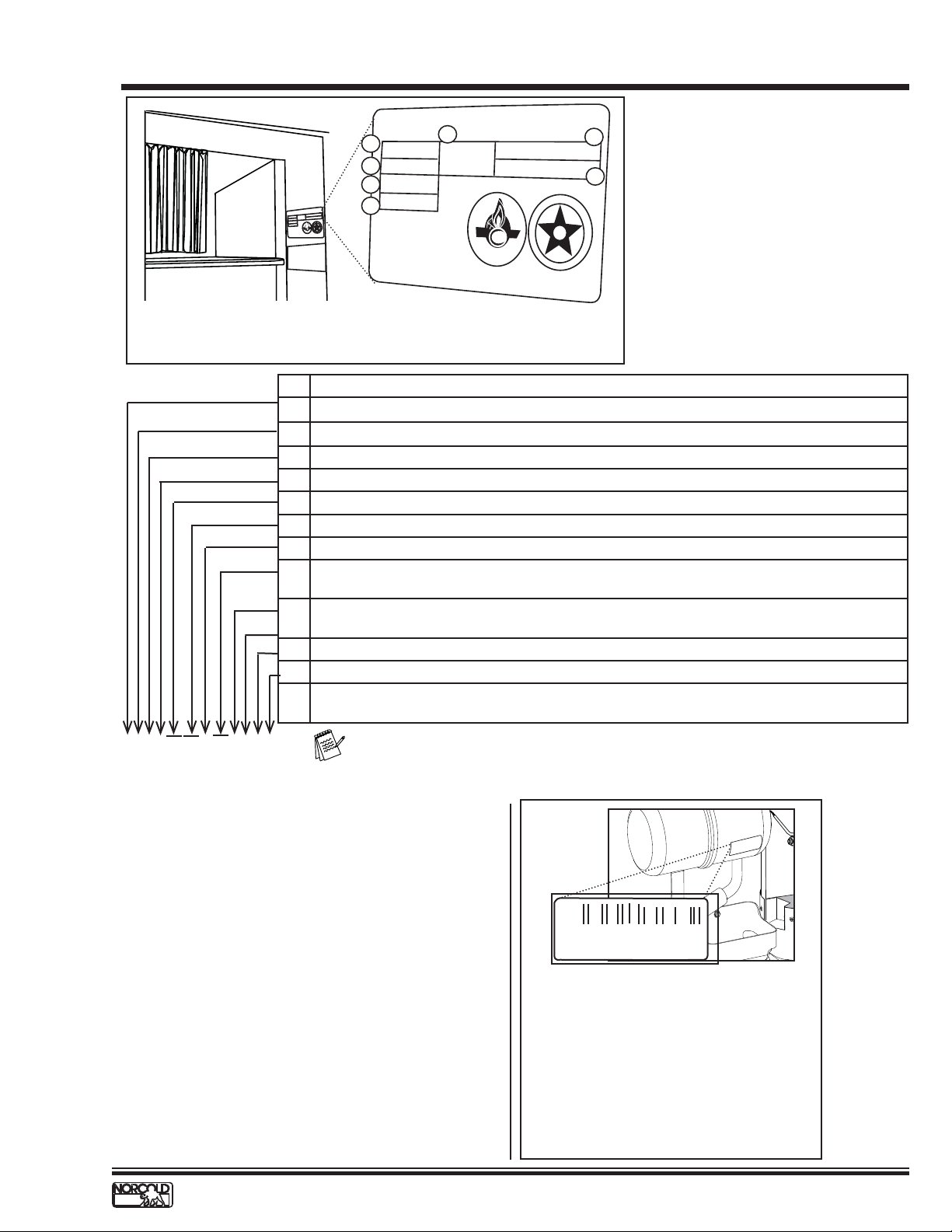
Information Label
The information label is located in the upper right corner of the
fresh food compartment just below the divider. See Fig. 1. The
label provides the following information:
• Serial number.
• Model number.
• LP gas (propane) pressure.
• Btu/h.
• AC voltage and amperage.
• DC voltage and amperage.
• Design certifi cation.
• Vent kit requirement.
Certifi cation and Code Requirements
NORCOLD
absorption refrigerators are certifi ed under the latest edition
of ANSI Z21.19B standards for installation in mobile homes
or recreational vehicles, and with the Canadian Standards
Association CAN/CGA-1.4-M94.
Electrical components are
®
NX6X / NX8X, NXA6X / NXA8X gas/electric
compliant.
About Installation
Refrigerator installation must conform with the NX6/NX8
Installation Manual for the NORCOLD
in effect. Installation must also comply with applicable local
codes and standards set by the relevant certifi cation agency.
Replacement Parts
Use only authorized NORCOLD
Generic parts do not meet NORCOLD
safety, reliability, and performance. The use of unauthorized
aftermarket or generic replacement parts voids the
refrigerator's limited warranty coverage.
®
limited warranty to be
®
replacement parts.
®
specifi cations for
T echnical Assistance
If unable to resolve technical issues using the information
provided in this manual, technical support is available through
NORCOLD
The following information is required to process technical
support requests; refer to the following page:
• Refrigerator Model Number
• Refrigerator Serial Number
• Refrigerator Cooling Unit Serial Number
• Recreational Vehicle (RV) Make/Model/Year
®
Customer Service Center:
Telephone: 1-800-444-7210
Fax: 1-734-769-2332
World Wide Web: www.norcold.com
4
www.norcold.com/cda
Refrigerator Service ManualNX6 / NX8 / NXA Models
MODEL IDENTIFICATION
xxxxxxxxxxxxxxxxxxxxxxxxxxx
xxxxxxxxxxxxxxxxxxxxxxxxxxx
ORC
N
xx
xxxxxxxxxxxxx
xxxxxxxxxxxxxxxxxxxxx
xxxxxxxxxxxxxxxxxxx
xxxxxxxxxxxxxxxxxxxx
xxxxxxxxxxxxxxxxxxxxxxxxx
xxxxxxxxxxxxxxxxxxxxxxxxx
x
NORCOLD
A
Serial Number
Model Number
B
Group Code
C
Input Pressure
BTUH
xxxxxxxxxxx
x
x
xxx
xxxx
xxxxxxxxxxxxxx
xxxx
x
xxxxxxxxxxxxxxx
D
OL
G
I
N
S
E
D
xxxx
x
x
x
xx
x
xxxx
xx
xx
x
xxxxx
x
x
xxxxx
xxxxxxx
x
xxxx
SA
C
xxxxx
E
F
R
T
I
xxxxx
xxxxxxxxxxx
xxxxxx
xxxxx
xxxxxxxxxxxxxxxxxx
x
x
x
xx
x
x
x
x
x
x
x
x
xx
x
x
x
x
x
x
xx
x
x
D
xxxxxxxxxxxxxxxxxxxxxxxxxxx
xxxxxxxxxxxxxxxxxxxxxxxxxxx
E
i
x
x
xxxxxxxxxxxxxxxxxxxxxxxxx
xxxxxxxxxxxxxxxxxxx
xxxxxxxxxxxxxxxxxxxxxxxxx
xxxxxxxxxxxxxxxxxxxxxxxxx
xxxxxxxxxxxxxxxxxxxxxxxxx
xxxxxxxxxxxxxxxxxxxxxxx
xxxxxxxxxxxxxxxxxxxxxxx
E
Refrigerant
x.xx
LBS.
test pressure
xxx VOLTS - AC xx HZ
x.xx AMPS xxx Watts
xx VDC xx HZ
x.x AMPS xx xx Watts
SA
Certied
Serial Number / Model Number Location
Fig. 1 - Refrigerator Information Label Location
Explanation
N = Norcold
1
X = Sequence number indicating custom features
2
6 or 8 = Approximate storage volume in cubic feet
3
X = Sequence number indicating custom features
4
Models available. Blank = 2-Way operation, .3=3-Way operation
5
Icemaker unit. Blank = does not have ice maker, IM = has icemaker
6
Blank = Is not equipped for low ambient operation, C = Is equipped for low ambient operation
7
Door design: Blank: Insert panel doors, SS: Stainless steal wrapped, BK: Black wrapped, WH:
8
White wrapped, WPM: Pewter Royce wrapped
Fan: Blank: No fan, F = Equipped (1) Fan, F2 = Equipped (2) Fans, V = Equipped (1) High
9
Velocity Fan
Door swing: L = Left-hand door swing, R = Right-hand door swing
10
P=Black acrylic door panels
11
Packaging Type: Blank: Corrugated packaging, T = Returnable packaging tray, M6 = 6-unit
12
multi-pack
A. Serial Number
F
G
I
G
S
E
N
D
B. Model Number
C. Group Code
D. BTu/h
E. Amount of refrigerant in cooling
C
E
D
R
E
i
F
T
I
unit
F. AC Voltage/amperage
G. DC Voltage/amperage
NX610.3 IM C BK X R P T
Note: The actual refrigerator label specifi es the features applicable to that unit.
Cooling Unit Serial Number
The cooling unit serial number appears on the cooling unit bar
code label. The label is affi xed to the surface of the cooling
unit leveling chamber.
NORCOLD
1167359
Cooling Unit Bar Code Location
Be sure to have the cooling unit serial
number available if you need technical
support on this component.
Fig. 2 - Cooling Unit Bar Code
Label Location.
www.norcold.com/cda
NX6 / NX8 / NXA ModelsRefrigerator Service Manual
5
SAFETY A WARENESS
Safety Notice
It is not possible to anticipate all of the conceivable ways
or conditions under which the refrigerator may be serviced
or to provide cautions as to all of the possible hazards that
may result. Standard and accepted safety precautions and
equipment should be used when working on electrical circuits
and handling toxic or fl ammable materials. Safety goggles and
other required protection should be used during any process
that can cause material removal, such as when removing a
leaking cooling unit and cleaning components.
Attention Statements
The safety alert symbol
CAUTION identifi es potential safety hazards or conditions.
The safety alert symbol with the appropriate heading appears on
all safety labels posted on the refrigerator and safety awareness
notices presented throughout this manual.
!
followed by the word WARNING or
!
WARNING
The above heading identifi es hazards or conditions,
which if ignored can cause serious injury, death, and/
or extensive property damage.
CAUTION
!
The above heading identifies hazards, which if
ignored can cause injury and/or property damage.
Safety Statements
Do not modify, alter, or equip the refrigerator to the use
!
of any other fuel (natural gas, butane, etc.). NX6X/NX8X,
NXA6X, NXA8X refrigerators are designed and equipped
for the use of LP gas–propane gas–only.
!
Incorrect installation, adjustment, alteration, or maintenance
of the refrigerator can cause personal injury, property
damage, or both.
!
Do not smoke, light fi res, or create sparks when working on
the propane gas system.
Do not use an open fl ame for leak testing any of the
!
propane gas system components. Propane gas is highly
fl ammable and explosive.
!
Always use two wrenches to tighten or loosen LP
gas connections. Damaged connections, piping, and
components create the potential for gas leaks.
!
All electrical connections and repairs to the refrigerator
must comply with all applicable codes. Refer to the
certifi cation and code requirements section of the NX6X/
NX8X Installation Manual.
!
Do not work on live electrical circuits. Turn off AC power
and DC power sources before attempting to remove,
service, or repair any of the refrigerator's electrical or
electronic components.
!
Do not modify, bypass, or eliminate any of the refrigerator's
electrical components, electronic circuits, or propane gas
system components.
!
Do not wet or spray liquids on or near electrical
connections or electronic components. Most liquids,
including leak detection solutions, are electrically
conductive and pose the potential for an electric shock
hazard, short electrical components, damage electronic
circuits, and/or ignite a fi re.
Do not use leak test solutions that contain ammonia or
!
chlorine. Ammonia and chlorine degrade copper and brass
components.
The cooling unit is a sealed system under pressure! Do
!
not try to repair or recharge the cooling unit. Do not bend,
drop, weld, drill, puncture, saw, or strike the cooling unit.
!
Handle a leaking cooling unit with extreme caution!
The cooling unit contains ammonia, hydrogen, and sodium
chromate. Ammonia can cause severe skin and eye burns.
Hydrogen is highly fl ammable, can ignite and burns with
an intense fl ame. Certain chromium compounds, such as
sodium chromate, are carcinogenic.
!
Do not use extension cords. Do not remove the grounding
prong from the refrigerator AC power cord. Do not use a
two prong adapter to connect the refrigerator to the AC
outlet.
Do not over-fuse electrical circuits. Use specifi ed fuses and
!
AWG wire sizes. The specifi cation section of this manual
provides fuse size information. Refer to the NX6XNX8X
Installation Manual for the correct AWG wire size
specifi cations.
!
Prevent child entrapment! Before disposing of the
refrigerator, remove all doors and fasten all shelves with
retainers.
Some of the refrigerator's metal components have sharp
!
corners and edges. Wear hand protection, such as cut
resistant gloves, and exercise extreme care when handling
the refrigerator.
!
Make sure all hardware such as hinges and fasteners
(retaining screws, etc.), are properly fastened.
6
www.norcold.com/cda
Refrigerator Service ManualNX6 / NX8 / NXA Models
SPECIFICATIONS
NX61 / NX81, NX64 / NX84, NXA64 / NXA84
NX61 / NX81 - Electronic
• Push Button - On/Off, Mode, and Temperature Set
• LED Indicator Lights
• Self-Diagnostic with Fault Indicators
• 2-Way Operation
• Three Separate Temperature Settings (With Backup Operating System Mode)
• Sleep Mode
NX64 / NX84, NXA64 / NXA84 - Electronic
• Push Button - On/Off, Mode, and Temperature Set
• Backlit LCD (Liquid Crystal Display) with Icon Indicators
• Self-Diagnostic with Fault Codes
• 2-Way Operation (Standard), 3-Way Operation (Optional)
• Nine Separate Temperature Settings (With Backup Operating System Mode)
• 10 Individual Diagnostic Screens
• Sleep Mode
Rough opening dimensions (H x W x D)
7
NX6XX, NXA6XX --------------------------------------------------------------------------------------- 52
NX8XX, NXA8XX ---------------------------------------------------------------------------------------59
/8
7
/8
in. x 23
in. x 23
Decorative panels dimensions
Thickness ------------------------------------------------------------------------------------------------------------------------- 3/16 in.
Freezer door (H x W, both models) ----------------------------------------------------------------15 11/16 in. x 21 19/32 in.
Upper panel ---------------------------------------------------------------------------------------------15 11/16 in. x 21 19/32 in.
Fresh food compartment (H x W)
NX61 / NX64 / NXA64 ------------------------------------------------------------------------------ 32 25/32 in. x 21 19/32 in.
NX81 / NX84 / NXA84 ------------------------------------------------------------------------------- 39 25/32 in. x 21 19/32 in.
1/2
in. x 24 in.
1/2
in. x 24 in.
DC power
DC input voltage requirements --------------------------------------------------------------------------- 10.5VDC to 15.4VDC
DC Fuse, F1 on Power Board --------------------------------------------------------Automotive Blade, Type APR-5A-Tan
DC Fuse, F1 on optional DC Board --------------------------------------------Automotive Blade, Type APR-30A-Green
DC Heater (Optional) ------------------------------280W/14VDC, (0.67 to 0.73), Current 16A to 18A @ 12VDC
Divider Heater ------------------------------------ 3.1W/12VDC, (43 to 50), Current 240mA to 279mA @ 12VDC
Gas Valve --------------------------------------- 1.75W/12VDC, (74 to 92), Current 130mA to 162mA @ 12VDC
Interior Light -------------------------------------------------GE #214, Miniature Automotive Light Bulb, ½ A @ 13.5VDC
AC power
AC input voltage requirements ------------------------------------------------------------------------------108VAC to 132VAC
AC Fuse, F2 on Power Board ------------------------- AGC Series, 8A, Fast Acting, Glass Tube (1/4 in. x 1-1/4 in.)
AC Heater--------------------------------------------- 300W/120VAC, (46 to 51), Current 2.3A to 2.6A @ 120VAC
LP gas (propane)
Operating pressure (Input pressure to gas valve) ------------------------------------------------- 10.5 in. to 11.5 in. W.C.
Burner rating (Heat output) --------------------------------------------------------------------------- 1420 Btu/h @ 11 in. W.C.
Burner orifi ce size -----------------------------------------------------------------------------------------------------------------LP15
Gas ignition ------------------------------------------------------------------------------------------ Electronic with fl ame sensing
Electrode tip-to-burner gap ---------------------------------------------------------------------------------------1/8 in. to 3/16 in.
Off-level operating limits
Side-to-side------------------------------------------------------------------------------------------------------3 degrees-maximum
Front-to-back ----------------------------------------------------------------------------------------------------6 degrees-maximum
Temperature Sensor ---------- ---------------------------------------- Thermistor, Fin mounted (10th fi n from the right)
www.norcold.com/cda
NX6 / NX8 / NXA ModelsRefrigerator Service Manual
7
THEORY OF OPERATION
Overview
The NX6X/NX8X MODEL gas absorption refrigerators are
comprised of two separate systems that together allow the
refrigerator to cool. When performing service it is important
to have a basic understanding of each system and their
interaction with one another and how this interaction provides
for cooling/refrigeration.
These two “systems” are the:
• Cooling Unit
• Refrigerator Controls (Electronic Controls)
Cooling Unit
The cooling unit is a self-contained gravity fl ow absorption
refrigeration system. The refrigerant charge is a solution of
water, ammonia, sodium hydroxide, and sodium chromate.
In order to produce cooling a precise heat must be applied to
the boiler area which in turn initiates a chemical reaction that
extracts heat from the freezer and fresh food compartments,
thus providing "cooling."
This precise heat is supplied to the cooling unit via heaters
and/or a LP gas burner which are controlled by the
refrigerators electronic controls. The refrigerant transfers the
heat from the freezer and fresh food cabinets to the absorber
coils. At the absorber coils the metal surface absorbs the heat
and air fl ow over the external surfaces of the coils carries
the heat away. A more detailed description of the absorption
process can be found under the heading “Cooling Unit
Detailed Description" on the following pages.
A thermal air current created by the rising hot air fl ows out of
the enclosure through either a roof exhaust vent or a sidewall
exhaust vent (depending on installation). The fl owing air
mass passes over the surface of the condenser fi ns where it
absorbs heat transferred from the ammonia vapors fl owing
through the condenser. The thermal airfl ow process creates
a "chimney effect" that creates a continuous draft of cooling
and combustion air. The fresh air drafted by the chimney effect
removes rejected heat, supports combustion, and expels
the exhaust gases produced by the combustion process.
Obstructions, restrictions, or modifi cations to vents or the
enclosure will affect the heat absorption cycle. Poor cooling
unit performance may be due to:
• Loose insulation interfering with the ventilation process
• Construction material or debris left in the enclosure
• Insect screen covering vents
• Plastic sheeting covering vents
• Items stored in the enclosure
• Modifi cations to vents or enclosure
• No roof or sidewall vent openings
Leveled Operation
The circulation of the refrigerant through the cooling unit is
accomplished by gravity fl ow; therefore, the refrigerator must
be operated leveled. Off-level operation affects the fl ow of the
refrigerant through the cooling system. The maximum off-level
operation limits are:
• 3° (Degrees) from side-to-side
• 6° (Degrees) from front-to-back
Exceeding the maximum off-level limits can permanently
damage the cooling unit. The cooling unit or its performance is
not affected when the vehicle is in motion.
Gradual Decrease in Cooling Effi ciency
A gradual decrease in cooling effi ciency is not a clear
indication of cooling system failure. Other factors that affect
cooling effi ciency include ventilation, the heat input, off-level
operation, lack of service and maintenance, inadequate
repairs, or unauthorized fi eld modifi cations. If any of these
factors exist and are not corrected, a replacement cooling
unit will also perform ineffi ciently or fail. Step-by-step
troubleshooting is the best approach when dealing with
a gradual decrease in cooling. It is important to consider
that, though not effi ciently, the cooling unit is working.
Troubleshooting should always begin by checking ventilation,
then thoroughly checking the cooling unit, and heat sources.
In the majority of reported cases, the problem is related to
the installation, which in turn hinders cooling unit ventilation.
Additionally, ambient air temperature plays a signifi cant role
if the unit is not installed correctly. Incorrect installation can
lead to poor ventilation, which in turn relates to poor cooling
performance.
The unit's service and maintenance history should be
considered when checking a cooling unit for poor cooling
performance. The service history and the scope of service
work performed may lead directly to cause and resolution
of a cooling problem. The cooling unit has to reach normal
operating temperatures before troubleshooting can take place.
It takes an average of four hours for the refrigerant to reach
normal operating temperatures. The time frame to reach
operating temperatures depends on ambient air temperature.
8
www.norcold.com/cda
Refrigerator Service ManualNX6 / NX8 / NXA Models
Theory of Operation - cont’d.
Gas Absorption System
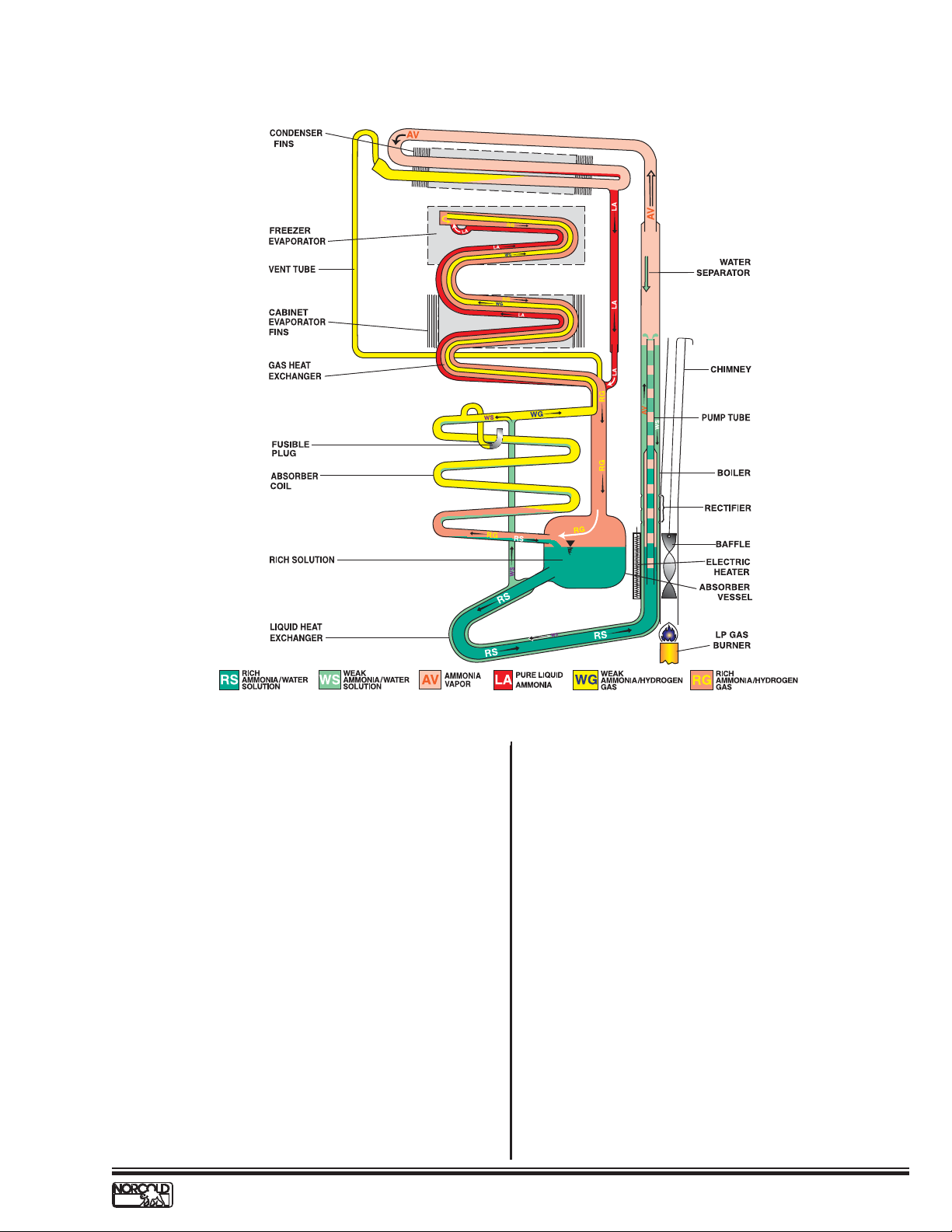
Fig. 3 - Gas Absorption System
A rich solution (RS) leaves the absorber vessel and passes
through the liquid heat exchanger to the bottom of the pump
tube. Utilizing a cartridge type heater (AC or DC) or a LP
gas burner, a precise heat is applied to this area which in
turn causes the temperature of the solution to rise. This
temperature increase causes ammonia and some water
vapor to be driven out of the solution, forming vapor bubbles
which push columns of liquid up the pump tube.
As these columns of liquid exit the pump tube the liquid falls
downward through the rectifi er where the temperature is
increased causing additional ammonia vapor to be released.
The remaining liquid, now a weak ammonia-water solution
(WS), fl ows through the external shell of the liquid heat
exchanger where it transfers its residual heat to the rich
solution (RS) and enters the top of the absorber coil at a
reduced temperature. The ammonia-water vapor passes
through the water separator whose reduced temperature
causes any water vapor to condense and drop back down to
the boiler mixing with the existing weak solution (WS). The
ammonia vapor (AV) rises and enters the condenser where
it condenses (liquefi es) into pure liquid ammonia (LA). The
liquid ammonia, via gravity, drops into the tubular coil of the
freezer and cabinet evaporators and wets the internal surface
of the tubes.
The weak ammonia-hydrogen gas that was previously
released at the top of the absorber coil passes over the
wetted surfaces of the evaporator tubing causing the liquid
ammonia to evaporate into the hydrogen. The now rich
ammonia-hydrogen gas mixture (RG) draws heat from inside
the refrigerator. The weight of the hydrogen-ammonia gas
mixture (RG) is heavier than that of the weak gas (WG).
Consequently, it falls through the gas heat exchanger into the
top of the absorber vessel. From this point it enters the bottom
of the absorber coil.
The rich ammonia-hydrogen gas mixture (RG) travels up
through the absorber and makes contact with the weak
solution (WS) traveling down from the top of the absorber. As
the weak solution (WS) drops through the absorber it absorbs
the ammonia from the rich ammonia-hydrogen gas mixture
(RS). The relatively pure hydrogen (WG) exits the top of the
absorber coils to the evaporator and the rich solution falls to
the bottom of the absorber vessel where the cycle starts again.
www.norcold.com/cda
NX6 / NX8 / NXA ModelsRefrigerator Service Manual
9

Theory of Operation - cont’d.
Electronic Controls
A precise heat is applied to the boiler area of the cooling
unit causing a chemical reaction within the cooling unit that
ultimately results in the refrigerator cooling. The heat applied is
done so by means of:
• Cartridge type heaters (AC or DC heaters)
positioned in heater wells welded to the surface of
the boiler
• LP Gas burner positioned below the boiler such
that the heat from the fl ame is directed across the
surface of the boiler
These heat sources are turned on/off via the combination of
the electronic controls and a temperature sensor located inside
the refrigerator fresh food compartment. A temperature setting
is set at the electronic controls and as the temperature sensor
warms and cools the heat source is turned on/off accordingly.
This process of turning on/off the heat source(s) can be
accomplished in various operating modes. These operating
modes are:
• Manual AC Mode - While operating in this mode
the AC cartridge type heater is operated to provide
heat to the boiler area of the cooling unit (2-way &
3-way models)
• Manual LP Gas Mode - While operating in this
mode the LP Gas burner is operated to provide
heat to the boiler area of the cooling unit (2-way &
3-way models)
• Manual DC Mode - While operating in this mode
the DC cartridge type heater is operated to provide
heat to the boiler area of the cooling unit (3-way
models only)
• Auto Mode - While operating in this mode the
electronic control will automatically select the
mode to be utilized. It will attempt to operate the
heat source requirements in the following order of
priority (All models):
• 1st Priority Choice - AC Electric (AC cartridge
type heater)
• 2nd Priority Choice – LP gas (LP Gas Burner)
• 3rd Priority Choice – (3-way models only) - DC
Electric (DC cartridge type heater)
Dependent upon the model number NX6X/NX8X refrigerators
are either considered 2-way or 3-way model refrigerators
(See Model Identifi cation section of this manual). 2-way
refrigerators are capable of operating priority choices 1 and/
or 2 via separate Manual Modes or an Automatic Mode. 3-way
refrigerators are capable of operating all 3 priority choices via
separate Manual Modes or an Automatic Mode.
The mode of operation and temperature setting is selected
via the optical display assembly located on the front of the
refrigerator. A thermistor is mounted on the fi n assembly
located inside the fresh food compartment. The thermistor
acts as a temperature sensor, reporting the temperature
sensed to the optical display. The optical display then relays
this information to the power board that then turns on/off the
appropriate heat source accordingly. The optical display board,
power board, thermistor, and other components within the
refrigerator are interconnected via a wire harness.
Manual AC Mode
To operate in the Manual AC mode the optical display must be
placed to operate in this mode. Once done so, the refrigerator
will cool via the AC mode and ONLY the AC mode. While in
the AC mode the refrigerators electronic controls will function
as follows:
The power board is responsible for:
• Measuring the AC input voltage
• Measuring the AC heater current
• Measuring the resistance value of the thermistor
• Turning ON/OFF the AC heater output
• Communicating with the Optical Display Board
The optical display board is responsible for:
• Determining if the AC input voltage is available or
not available
• Determining if the AC heater current is acceptable
or not acceptable
• Determining if the thermistor value is above or
below preset temperature range cut-in/cut-out
values
• Determining when the power board is to turn ON/
OFF the AC heater output
• Communicating with the Power Board
Theory of Operation - Manual AC Mode
AC voltage is applied to the power board via the AC power
cord at terminals L1 (Hot) and L2 (Neutral). This AC voltage
passes through the AGC Series, 8A, Fast Acting, Glass Tube
Fuse (F2) where it is then measured. This measurement is
communicated to the optical display board which determines
if the applied voltage is below or above 85VAC. If the voltage
is above 85VAC, the determination is that AC voltage is
available. If not, it is determined that AC voltage is not
available and the appropriate voltage related fault will be
displayed on the optical display.
• NX61 / NX81 = Power ON indicator is Solid RED
• NX64 / NX84 = "no AC" with audible alarm/beeper
• NXA64 / NXA84 = "no AC" with audible alarm/
beeper
The power board also measures the thermistor value and
reports it to the optical display board. The thermistor, a
temperature device whose internal resistance goes down as
the temperature goes up, is connected to the power board via
terminals P2-1 and P2-6. The optical display board compares
the actual thermistor value to preset cut-in and cut-out
temperature values for each of the particular temperature
settings. Should the thermistor value fall below a particular
cut-in value it will request the power board to turn ON the AC
heater relay (K2). Should the thermistor value go above a
particular cut-out value it will request the power board to turn
OFF the AC heater relay.
Any time relay K2 is turned ON, AC voltage is applied to
the AC heater via the now closed K2-contacts. Any time AC
voltage is applied to the AC heater, an AC current is produced.
10
www.norcold.com/cda
Refrigerator Service ManualNX6 / NX8 / NXA Models

Theory of Operation - cont’d.
This AC current is measured by the power board and its value
is passed on to the optical display board. The optical display
board determines if the AC current is or is not within the
specifi ed limitations. Should the current fall below ½ ampere,
the optical display board will display the appropriate AC current
related fault.
• NX61 / NX81 = Power ON indicator light fl ashes
RED once, OFF for 5-seconds, repeats
• NX64 / NX84 = "AC HE" with audible alarm/beeper
• NXA64 / NXA84 = "AC HE" with audible alarm/
beeper
Manual LP Gas Mode
To operate in the Manual LP Gas mode the optical display
must be placed to operate in this mode. Once done so, the
refrigerator will cool via the LP Gas mode and ONLY the
LP Gas mode. While in the LP gas mode the refrigerators
electronic controls will function as follows:
The power board is responsible for:
• Measuring the resistance value of the thermistor
• Determining the presence of a fl ame
• Turning ON/OFF the gas valve output
• Turning ON/OFF the igniter output
• Communicating with the Optical Display Board
The optical display board is responsible for:
• Deciding if the thermistor value is above or below
preset temperature range cut-in/cut-out values
• Deciding when to turn ON and OFF the gas valve
• Communicating with the Power Board
Theory of Operation - Manual LP Gas Mode
The power board measures the thermistor value and reports
it to the optical display board. The thermistor, a temperature
device whose internal resistance goes down as the
temperature goes up, is connected to the power board via
terminals P2-1 and P2-6. The optical display board compares
the actual thermistor value to preset cut-in and cut-out
temperature values for each of the particular temperature
settings. Should the thermistor value fall below a particular
cut-in value the optical display will request the power board to
turn ON the gas valve relay (K1) and high voltage transformer
(T1) outputs.
Anytime relay K1 is turned ON, 12VDC passes through the
now closed K1 contacts to terminal P1-10 of the power board
and out to the gas valve solenoid, energizing the gas valve.
With the gas valve energized LP gas fl ows out to the burner
tube. Simultaneously, energy pulses from the high voltage
transformer (T1) are carried out to the burner via the spark
sense electrode wire. As the energy pulses reach the end of
the electrode they jump across the gap between the electrode
and the burner creating sparks. The sparks ignite the LP gas
and a fl ame is established. Via the fl ame rectifi cation process
a signal is then sent back to the power board through the
spark sense electrode wire letting the power board know there
is a fl ame present.
Knowing a fl ame is present; the power board deactivates
the spark output. At the same time; the power board
communicates to the display letting it know a fl ame is now
present. When the thermistor value reaches a particular
cut-out value the optical display will request the power board
to turn OFF the gas valve output, allowing the fl ame to
extinguish.
If for some reason the fl ame goes away while there is a call
for cooling, at the request of the optical display board, the
power board will turn the high voltage transformer back on in
an attempt to re-ignite the propane. For safety reasons the
sparking at the burner will last for a maximum of 30 seconds,
at which time the gas valve/high voltage transformer outputs
will be turned off and an error will be displayed via the optical
display indicating a gas lockout condition. To reset this gas
lockout condition the controls must be powered off/on.
• NX61 / NX81 = Power ON indicator is SOLID RED
• NX64 / NX84 = "no FL" with audible alarm/beeper
• NXA64 / NXA84 = "no FL" with audible alarm/
beeper
Manual DC Mode (3-way models only)
To operate in the Manual DC mode the optical display must be
placed to operate in this mode. Once done so, the refrigerator
will cool via the DC mode and ONLY the DC mode. While in
the DC mode the refrigerator electronic control will function as
follows:
The power board is responsible for:
• Measuring the resistance value of the thermistor
• Communicating with the Optical Display Board
• Communicating with the DC Board
The optical display board is responsible for:
• Determining if the thermistor value is above or below
preset temperature range cut-in/cut-out values
• Determining when the DC board is to turn ON/OFF the
DC heater output
• Communicating with the power board
• Communicating with the DC board
The DC board is responsible for:
• Turning ON/OFF the DC heater output
• Measuring the DC heater current
• Communicating with the Optical Display Board
• Communicating with the Power Board
www.norcold.com/cda
NX6 / NX8 / NXA ModelsRefrigerator Service Manual
11
Theory of Operation - cont’d.
Theory of Operation - Manual DC Mode
(3-way models only)
The power board measures the thermistor value and reports
it to the optical display board. The thermistor, a temperature
device whose internal resistance goes down as the
temperature goes up, is connected to the power board via
terminals P2-1 and P2-6. The optical display board compares
the actual thermistor value to preset cut-in and cut-out
temperature values for each of the particular temperature
settings. Should the thermistor value fall below a particular cutin value the optical display will request the DC board to turn
ON the DC heater relay (K1) on the DC board.
Should the thermistor value go above a particular cut-out value
it will request the DC board to turn OFF the DC heater relay.
Any time relay K1 of the DC board is turned ON, DC voltage
passes through the 30A, automotive style, SAE J1284 fuse (F1
on the DC board), through the now closed K1-contacts, and
on out to the DC heater via DC board terminals DC_HTR and
HTR_GND. Any time DC voltage is applied to the DC heater,
a DC current is produced. This DC current is measured by
the DC board and its value is passed on to the optical display
board. The optical display board determines if the DC current
is or is not within the specifi ed limitations. Should the current
fall below the specifi ed limits the optical display board will
display the appropriate DC current related fault.
• NX64.3 / NX84.3 = "dc HE" with audible alarm/
beeper
• NXA64.3 / NXA84.3 = "dc HE" with audible alarm/
beeper
The optical display board is responsible for:
• Determining if the AC input voltage is available or
not available
• Determining if the AC heater current is acceptable
or not acceptable
• Determining if the thermistor value is above or
below preset temperature range cut-in/cut-out
values
• Determining when the power board is to turn ON/
OFF the AC heater output
• Determining when to turn ON and OFF the gas
valve
• Determining when to turn ON/OFF the DC heater
output
• Communicating with the Power Board
• Communicating with the DC Board (3-way models
only)
The DC board (3-way models only) is responsible for:
• Turning ON/OFF the DC heater output
• Measuring the DC heater current
• Communicating with the Optical Display Board
• Communicating with the Power Board
Auto Mode
To operate in the Auto mode the optical display must be
placed to operate in this mode. Once done so, 2-way model
refrigerators will cool via the Auto AC mode or Auto LP Gas
mode and (3-way models) via the Auto AC mode, Auto LP
Gas mode, or the Auto DC mode. While in the Auto mode the
refrigerators electronic controls will function as follows:
The power board is responsible for:
• Measuring the AC input voltage
• Turning ON/OFF the AC heater output
• Measuring the AC heater current
• Turning ON/OFF the gas valve output
• Turning ON/OFF the igniter output
• Determining the presence of a fl ame
• Communicating with the Optical Display Board
• Communicating with the DC Board (3-way models
only)
Theory of Operation Auto Modes
AC voltage may or may not be applied to the power board
via the AC power cord at terminals L1 (Hot) and L2 (Neutral).
This AC voltage will pass through the AGC Series, 8A, Fast
Acting, Glass Tube Fuse (F2) where it is then measured. This
measurement is communicated to the optical display board
which determines if the applied voltage is below or above
85VAC. If the voltage is above 85VAC the determination is
that AC voltage is available and the optical display board will
request the power board to operate via the Auto AC Mode.
If the voltage is below 85VAC the determination is that AC
voltage is NOT available and the optical display board will
automatically default to the Auto LP Gas Mode and request
the power board to operate via the Auto LP Gas Mode (see
below). If the control is not able to establish a fl ame while
operating in the Auto LP Gas Mode the optical display board
will:
2-WAY MODELS:
Automatically default back to the Auto AC mode and wait for
AC voltage to return, displaying the following fault code
• NX61 / NX81 Models: Solid RED power indicator
light
• NX64 / NX84 Models: "no AC" "no FL" with audible
alarm/beeper
• NXA64 / NXA84 Models: "no AC" "no FL" with
audible alarm/beeper
3-WAY MODELS:
Automatically default to the Auto DC mode and request the DC
board to operate via the Auto DC mode.
12
www.norcold.com/cda
Refrigerator Service ManualNX6 / NX8 / NXA Models
Theory of Operation - cont’d.
Auto AC Mode
When operating in the Auto AC mode the power board
measures the thermistor value and communicates it to the
optical display board. The thermistor, a temperature device
whose internal resistance goes down as the temperature goes
up, is connected to the power board via terminals P2-1 and
P2-6. The optical display board compares the actual thermistor
value to preset cut-in and cut-out temperature values for each
of the particular temperature settings. Should the thermistor
value fall below a particular cut-in value it will request the
power board to turn ON the AC heater relay (K2). Should the
thermistor value go above a particular cut-out value it will
request the power board to turn OFF the AC heater relay.
Anytime relay K2 is turned ON, AC voltage is applied to
the AC heater via the now closed K2 contacts. Anytime AC
voltage is applied to the AC heater, AC current is produced.
This AC current is measured by the power board and its
value communicated to the optical display board. The optical
display board determines if the AC current is within specifi ed
limitations. If below the minimum specifi ed limit, the optical
display board will automatically default to the Auto LP Gas
Mode and request the power board to operate via the Auto
LP Gas Mode. AC related faults (Voltage or Current) are not
displayed while operating in the Auto Mode of operation.
Auto LP Gas Mode
When operating in the Auto LP Gas mode the power board
measures the thermistor value and communicates it to the
optical display board. The thermistor, a temperature device
whose internal resistance goes down as the temperature goes
up, is connected to the power board via terminals P2-1 and
P2-6. The optical display board compares the actual thermistor
value to preset cut-in and cut-out temperature values for each
of the particular temperature settings. Should the thermistor
value fall below a particular cut-in value the optical display
board simultaneously requests the power board to turn ON gas
valve relay (K1) and high voltage transformer (T1) outputs.
Anytime relay K1 is turned ON, 12VDC passes through the
now closed K1 contacts to terminal P1-10 of the power board
and out to the gas valve solenoid, energizing the gas valve.
With the gas valve energized LP gas fl ows to the burner
tube. Simultaneously, energy pulses from the high voltage
transformer (T1) are carried out to the burner via the spark
sense electrode wire. As the energy pulses reach the end of
the electrode they jump across the gap between the electrode
and the burner creating sparks. The sparks ignite the LP gas
and a fl ame is established.
Via the fl ame rectifi cation process a signal is then sent back to
the power board through the spark sense electrode wire letting
the power board know there is a fl ame present. Knowing
a fl ame is present; the power board deactivates the spark
output. At the same time; the power board communicates to
the display letting it know a fl ame is now present.
When the thermistor value reaches a particular cut-out value
the optical display will request the power board to turn OFF the
gas valve output, allowing the fl ame to extinguish. If for some
reason the fl ame goes away while there is a call for cooling,
the power board will turn the high voltage transformer back
on and attempt to re-ignite the propane. For safety reasons
the sparking at the burner (trial for ignition time) will last a
maximum of 30 seconds, at which time the gas valve/high
voltage transformer outputs will be turned off and the LP Gas
mode will be locked out.
2-way models will automatically default back to the Auto AC
mode and wait, indefi nitely, for AC voltage to return. The
optical display board will display:
• NX61 / NX81: Solid RED power indicator light
• NX64 / NX84: "no AC" "no FL" with audible alarm/
beeper
• NXA64 / NXA84: "no AC" "no FL" with audible
alarm/beeper
3-way models will automatically default to the Auto DC mode
and request the DC board to operate via the Auto DC Mode.
Auto DC Mode (3-way models only)
When operating in the Auto DC mode the power board
measures the thermistor value and communicates it to the
optical display board. The thermistor, a temperature device
whose internal resistance goes down as the temperature goes
up, is connected to the power board via terminals P2-1 and
P2-6. The optical display board compares the actual thermistor
value to preset cut-in and cut-out temperature values for each
of the particular temperature settings. Should the thermistor
value fall below a particular cut-in value the optical display
board requests the DC board to turn ON DC heater relay (K1).
Should the thermistor value go above a particular cut-out
value it will request the DC board to turn OFF the DC heater
relay. Anytime relay K1 on the DC board is turned ON, 12VDC
passes through the now closed K1 contacts to terminal DC_
HTR of the DC board and out to the DC heater. Any time DC
voltage is applied to the DC heater, DC current is produced.
This DC current is measured by the DC board and its value
communicated to the optical display board. The optical
display board determines if the DC current is within specifi ed
limitations. If below the minimum specifi ed limit, the optical
display board will display:
• NX64.3 / NX84.3: "dc HE" with audible alarm/beeper
• NXA64.3 / NXA84.3: "dc HE" with audible alarm/beeper
•
Background Operations
Interior Light / Door Switch
The interior-light/door switch is a normally open reed switch
that is an integral component of the optical display board.
Theory of Operation - Interior Light / Door Switch
The magnetic pull from a permanent magnet located
underneath the top door trim maintains the reed switch
(N) contacts closed (light off) when the door is fully closed.
Opening the door breaks the magnetic pull, which in turn
causes the reed switch contacts to open (light on). The optical
display board senses the reed switch contacts are open and in
turn:
• Requests that the power board turn ON the K4
relay. Anytime relay K4 on the power board is
turned ON, 12VDC passes through the now closed
K4 contacts to terminal P1-7 of the power board
and out to the interior light.
• Initiates a 2-minute timer that once timed out
requests the power board to turn off the K4 relay.
This prevents the interior light from being left on in
the event the door is not completely shut. NX64/
NX84, NXA64 / NXA84 model refrigerators will also
display: "dr" with an audible alarm/beeper.
Note: Anytime the door is sensed open the
divider heater output will be turned off.
www.norcold.com/cda
NX6 / NX8 / NXA ModelsRefrigerator Service Manual
13
Theory of Operation - cont’d.
Moisture Reduction Heater (Divider Heater)
The divider heater is a low wattage heater used to reduce/
eliminate sweating on the surface of the plastic area between
the freezer and fresh food compartments, i.e. the divider
area. Due to the cooling nature of the refrigerator, the divider
area, especially on hot humid days, tends to be cooler than
that of the air around it. This causes the divider surface to
be below the dew point of the surrounding air and as a result
moisture or sweating develops. The divider heater, which is
not replaceable because it is foamed into place, consists of a
resistance wire placed atop one side of an adhesive backed
piece of foil adhered to the back of the divider area. Applying
12VDC to the resistance wire causes the wire to warm up. As
the wire warms up heat is transferred throughout the area of
the foil and subsequently the divider area. The added heat to
the divider area keeps the surface temperature above the dew
point of the surrounding air thus eliminating the occurrence of
sweating.
Theory of Operation - Moisture Reduction Heater (Divider
Heater)
The divider heater is connected between the power board
at P1-8 and the optical display board at P1-5. When the
refrigerator is fi rst powered on the power board measures the
value of the DC input voltage and communicates this value to
the optical display board. Providing the value of the DC input
voltage is greater than 10.5VDC the optical display board will
request the power board to turn ON relay K5. Anytime relay K5
on the power board is turned ON, 12VDC passes through the
now closed K5 contacts to terminal P1-8 of the power board
and out to one side of the divider heater. The other side of the
divider heater is tied to 12 volt ground via the white/violet wire
connected between P1-4 of the optical display and P2-4 of
the power board. Anytime the optical display senses the door
is open, it requests the power board to turn off K5. Once the
door is closed the optical display will request the power board
to turn K5 back on. Anytime the DC input voltage falls below
10.5VDC the optical display will request the power board to
turn off K5. Anytime K5 is turned off due to low DC voltage it
will not be turned back on until the DC input voltage has gone
above 11.5VDC.
Backup Operating System (BOS) Mode
The refrigerator has the ability to continue cooling in the event
the thermistor (temperature sensor) becomes inoperable.
Should the thermistor become electrically open or shorted the
electronic controls will revert to this backup operating mode,
allowing the refrigerator to continue cooling until it can be
serviced.
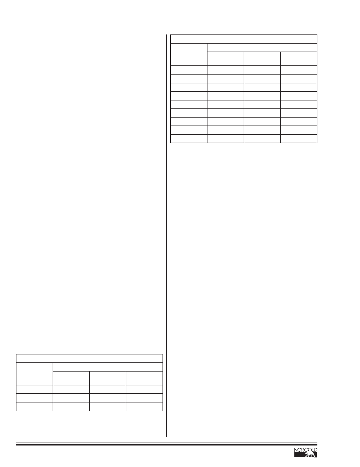
Temperature set points and BOS duty cycles for each model
are as follows:
NX64 / NX84, NXA64 / NXA84 MODELS
Temperature
Setting
1122048
2183042
3244036
4305030
5366024
6427018
7488012
854906
9 60 100 0
On Time
(Minutes)
Cooling Cycle
Duty Cycle
(%)
Off Time
(Minutes)
Table 2: Temperature Set Points NX64 / NX84, NXA64 / NXA84
Theory of Operation - Backup Operating System (BOS)
Mode
The power board measures the thermistor value and
communicates it to the optical display board. Should it
sense the thermistor is inoperable (electrically shorted/open,
unplugged, damaged, etc.) the optical display board will
activate the BOS mode. While operating in the BOS mode
the thermistor will be ignored and the temperature set point
will be interpreted as a duty cycle instead of a temperature
setting. This duty cycle will maintain refrigerator cooling by
controlling the length of time the heat source outputs (AC
heater, LP burner, or DC heater) are energized. The duty
cycle, or length of time the cooling cycle is regulated, can be
manually controlled via the TEMP SET button. When a colder
temperature is desired, changing the temperature setting
to the next "colder" setting will provide additional cooling by
lengthening the cooling cycle. When a warmer temperature is
desired, changing the temperature setting to a warmer setting
shortens the cooling cycle. The cycle period is 1 hour, giving a
minimum ON time of 12 minutes.
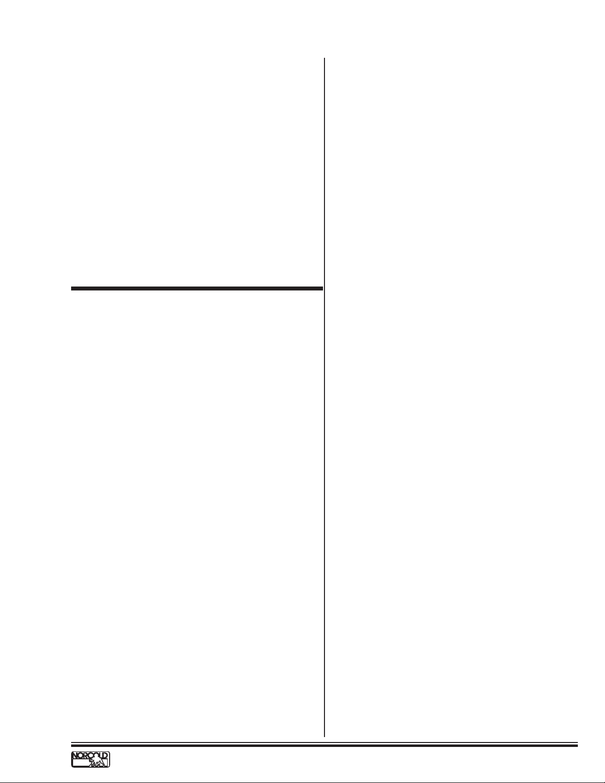
Defrost Operation
Although the refrigerator is NOT frost free, it is designed to
limit frost build up on the fresh food fi ns (metal fi ns mounted
on the back wall of the fresh food compartment). This is done
by simply turning off the heat source output, which in turn,
momentarily suspends cooling. As the fi n temperature rises,
the frost melts.
Theory of Operation - Defrost Operation
NX61 / NX81 MODELS
Temperature
Setting
Cold 12 20 48
Colder 36 60 24
Coldest 60 100 0
On Time
(Minutes)
Cooling Cycle
Duty Cycle
(%)
Off Time
(Minutes)
Table 1: Temperature Set Points NX61 / NX81
14
Every 49 hours of operation the refrigerator will enter a defrost
mode. While in the defrost mode the power board monitors the
thermistor value, reporting it to the optical display board. If the
thermistor value is greater than 38°F the optical display will
exit the defrost mode, reset the 49 hour timer, and continue
normal operation. If the thermistor value is less than 38°F the
optical display will request that the power board turn OFF the
applicable heat source output, be it one of the AC/DC heaters
or the LP gas burner, until the thermistor value reaches 38°F.
Once the 38°F requirement is met the optical display will exit
the defrost mode, reset the 49 hour timer, and continue normal
operation.
www.norcold.com/cda
Refrigerator Service ManualNX6 / NX8 / NXA Models
Theory of Operation - cont’d.
Auxiliary Output
The auxiliary output is used to power auxiliary loads such as a
fan or waterline heater. The voltage at this output is whatever
the DC input voltage connected to power board terminals
12VDC and GND is. That is to say, if the DC input voltage to
the refrigerator is 11VDC then the auxiliary output voltage will
be 11VDC.
Theory of Operation - Auxiliary Output
When the ON button of the optical display board is pressed,
relay K3 on the power board is turned ON; see On-Off Theory
of Operation for detailed explanation. Anytime relay K3 is ON,
the DC input voltage connected at the refrigerator (terminal
12VDC) passes through the now closed K3 contacts to terminal
P1-5 of the power board. The DC ground connection (terminal
GND) is electrically tied to power board terminal P1-3. This
auxiliary output will be present anytime the refrigerator is ON.
DIAGNOSTIC PRECHECKS
Prior to performing the diagnostic steps called out in the
following pages; fi rst verify these four important diagnostic pre-
checks. In most cases doing so, in and of itself, will remedy the
problem at hand.
1. The refrigerator is plugged into a known working AC
outlet with a voltage between 108VAC and 132VAC
2. Extension cords are not being used to supply AC power
to the refrigerator
3. The refrigerator is connected to a known working DC
power supply and/or battery supplying between 10.5
and 15.4VDC
4. LP gas is available to the refrigerator and is regulated
between 10.5 and 11.5”WC (Inches of Water Column)
www.norcold.com/cda
NX6 / NX8 / NXA ModelsRefrigerator Service Manual
15
FAULT CODES
NX61 / NX81 Fault Codes
The NX61/NX81 model refrigerators have the ability to
recognize various fault conditions and will display a unique
error/fault code accordingly. With the exception of the
thermistor fault which is displayed by fl ashing the cold setting
snowfl ake on and off (while the optical display is awake), all
fault codes are displayed via the power ON indicator and will
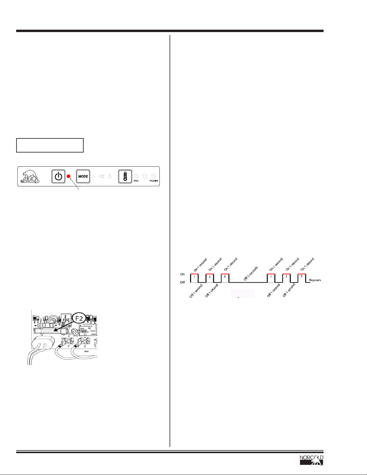
be RED in color.
Should the selected heat source input for a particular mode
not be available, the power ON indicator light will be ON
continuously. In other words, the power ON indicator will be
solid RED.
Solid Red Indicator Light
MODE
NORCOLD
A
CONSTANT RED INDICATOR LIGHT
The following conditions will cause the power ON indicator to
be solid RED:
COLD
COLDEST
Manual LP Mode:
A fl ame was NOT established or a fl ame was NOT sensed
Verify:
• All LP gas shutoff valves (including manual shutoff on
gas valve itself) are open
• LP Gas pressure at refrigerator is 11.5” W.C. (water
column)
• LP gas supply line is free of air
• The burner is clean
• The electrode-to-burner air gap is between 1/8” and
3/16”
• The spark-sense igniter wire is installed correctly and in
good operating condition / continuity
• Gas valve solenoid is in good operating condition (Coil
resistance 74 to 92)
• Wires to the gas valve are connected and in good
operating condition / continuity
• Power Board supplies 12VDC to gas valve when
required
• Replace Power Board.
NOR000122-0A
ALL other fault codes will be displayed using fl ash patterns.
The term “fl ash pattern” simply means the power ON indicator
light is turned ON and OFF to create a numeric pattern. These
fl ash patterns directly correspond to particular fault codes.
That is to say, for example, fault code 3 will be indicated by
fl ashing the power ON indicator light RED 3-times, followed
by a 5-second pause, and then repeated as long as the fault
condition is present. See Fig. 4 below.
Manual AC Mode:
The AC input voltage to the refrigerator was sensed to be less
than 85VAC
Verify:
• The refrigerator is plugged into a known working AC
outlet supplying a minimum of 85VAC
• The AC power cord is in good operating condition
• The glass 8-amp fuse (F2) on the Power Board is intact
• Replace Power Board.
NOR000123A
Fig. 4 - Flash Patterns
16
www.norcold.com/cda
Refrigerator Service ManualNX6 / NX8 / NXA Models
NX61 / NX81 Fault Codes - cont’d
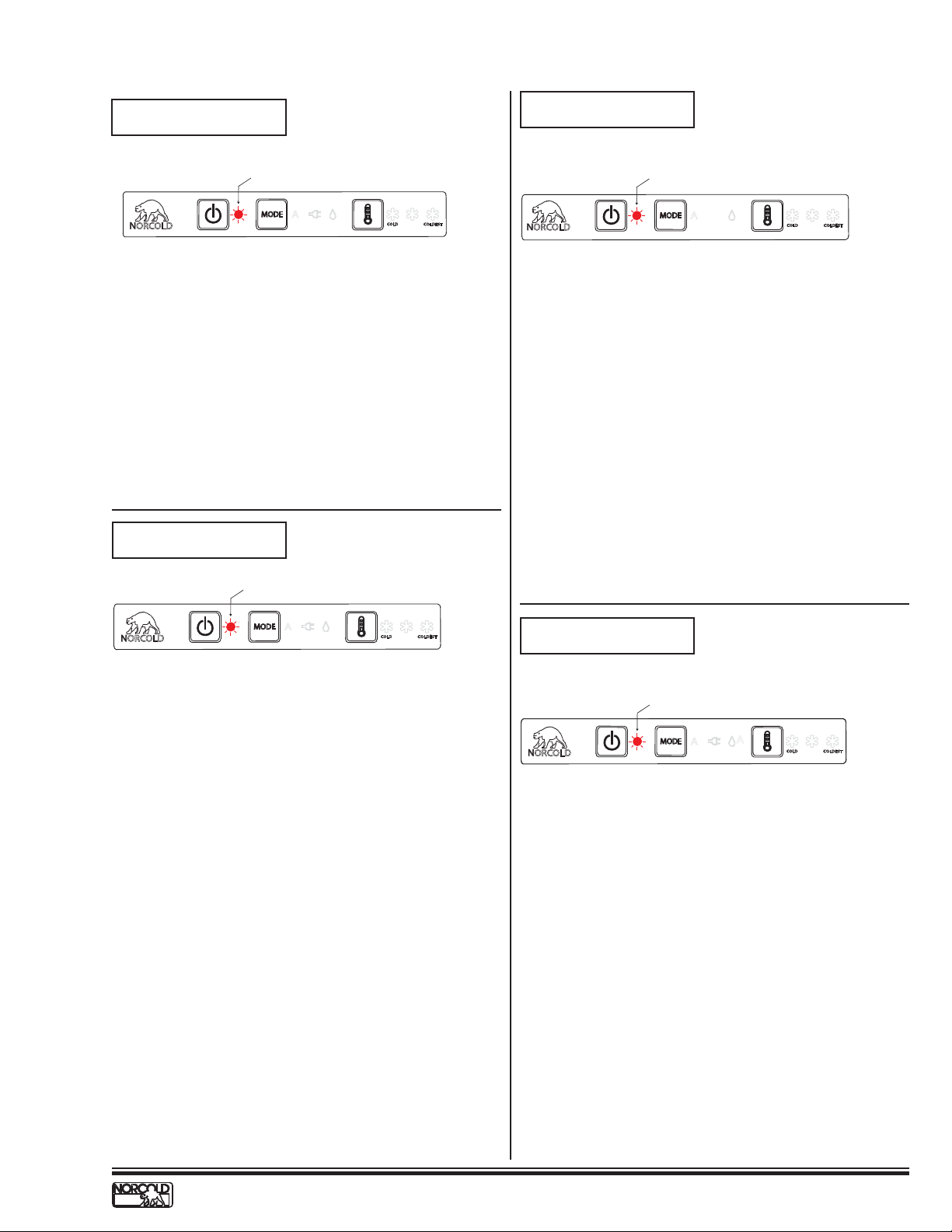
Fault / Flash Pattern 1
AC Heater Error
Power ON indicator light flashes ON once, OFF for 5-seconds, repeats
MODE
NORCOLD
A
COLD
COLDEST
NOR000122-1A
Flash Pattern “1” means the Power Board sensed the AC
heater current to be too low. This fault can only be displayed
while operating in the Manual AC Mode.
Verify:
• AC heater connections are in good repair and are
properly connected to the Power Board; refer to
refrigerator wiring diagram "Wiring Pictorial" on page
53 for proper connection.
• AC heater resistance measures between 46 and 51;
if not in range, replace AC heater.
• Replace power board.
Fault / Flash Pattern 2
Service Error
Fault / Flash Pattern 3
Open High Limit
Power ON indicator light flashes ON three times, OFF for 5-seconds, repeats
MODE
NORCOLD
A
COLD
COLDEST
NOR000122-3A
Flash Pattern "3" means the Power Board sensed the high
limit thermal switch is open. This thermal switch is mounted to
the metal insulation pack mounted above the burner. This fault
can be displayed in ANY MODE.
Verify:
• Is thermal switch electrically open, i.e. has it tripped?
• If no, verify wiring is connected properly. Refer to
refrigerator wiring diagram "Wiring Pictorial" on page
53 for proper connection.
• Replace power board.
Power ON indicator light flashes ON two times, OFF for 5-seconds, repeats
MODE
NORCOLD
A
COLD
COLDEST
NOR000122-2A
Flash Pattern “2” means the Power Board detected an internal
fault. This fault can be reset by powering the refrigerator OFF
and back ON. Should this fault continue to be displayed after
being reset, the Power Board should be replaced. This fault
can be displayed in ANY MODE.
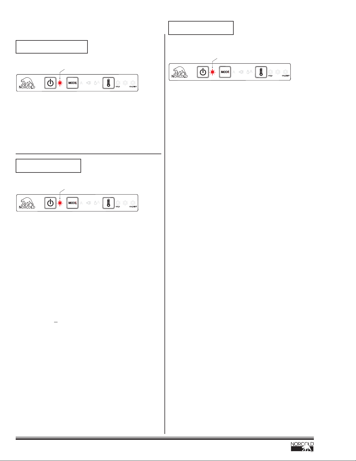
Fault / Flash Pattern 4
AC Relay Error
Power ON indicator light flashes ON four times, OFF for 5-seconds, repeats
NORCOLD
MODE
A
A
COLD
COLDEST
NOR000122-4A
Flash Pattern "4" means the AC heater relay contacts of relay
K2, on the Power Board, are stuck closed. This fault can be
displayed in ANY MODE.
• Replace the Power Board
www.norcold.com/cda
NX6 / NX8 / NXA ModelsRefrigerator Service Manual
17
NX61 / NX81 Fault Codes - cont’d
Fault / Flash Pattern 9
LOW DC (2) Error
Fault / Flash Pattern 5
Flame On Should Not Be On
Power ON indicator light flashes ON five times, OFF for 5-seconds, repeats
NORCOLD
MODE
A
A
COLD
COLDEST
NOR000122-5A
Flash Pattern "5" means the gas valve is “mechanically” stuck
open and subsequently the Power Board has sensed a fl ame
present when there should not be. This fault can be displayed
in ANY MODE.
• Replace the gas valve
Fault / Flash Pattern 8
LOW DC (1) Error
Power ON indicator light flashes ON eight times, OFF for 5-seconds, repeats
NORCOLD
MODE
A
A
COLD
COLDEST
NOR000122-8A
Power ON indicator light flashes ON nine times, OFF for 5-seconds, repeats
A
NORCOLD
MODE
A
A
COLD
COLDEST
NOR000122-9A
Flash Pattern "9" means the DC voltage to the refrigerator is
less than 8.5 volts DC. All outputs are inhibited. This fault will
automatically reset and outputs will be allowed to operate once
the DC input voltage rises above 9.0 VDC (above 10.5 for
3-way models). This fault can be displayed in ANY MODE.
Verify:
• That the battery charging equipment of the vehicle is
operational
• That the AC/DC converter is operational (if applicable)
• Contact Customer Service for further instructions.
Flash Pattern "8" means the refrigerator attempted to ignite or
re-ignite the burner when the DC input voltage was less than
10.0 VDC. The gas valve/igniter outputs are inhibited when
there is a call for cooling and the DC voltage is less than 10.0
VDC. Should there be a call for cooling while the DC input
voltage is greater than 10.0 VDC and the DC input voltage
then falls below 10.0 VDC, the gas valve will remain energized
and no fault will be displayed. This fault can only be displayed
in the Auto and Manual LP modes.
Verify:
• That the battery charging equipment of the vehicle is
operational
• That the AC/DC converter is operational (if applicable)
• If voltage is
>10.0 VDC replace power board
18
www.norcold.com/cda
Refrigerator Service ManualNX6 / NX8 / NXA Models
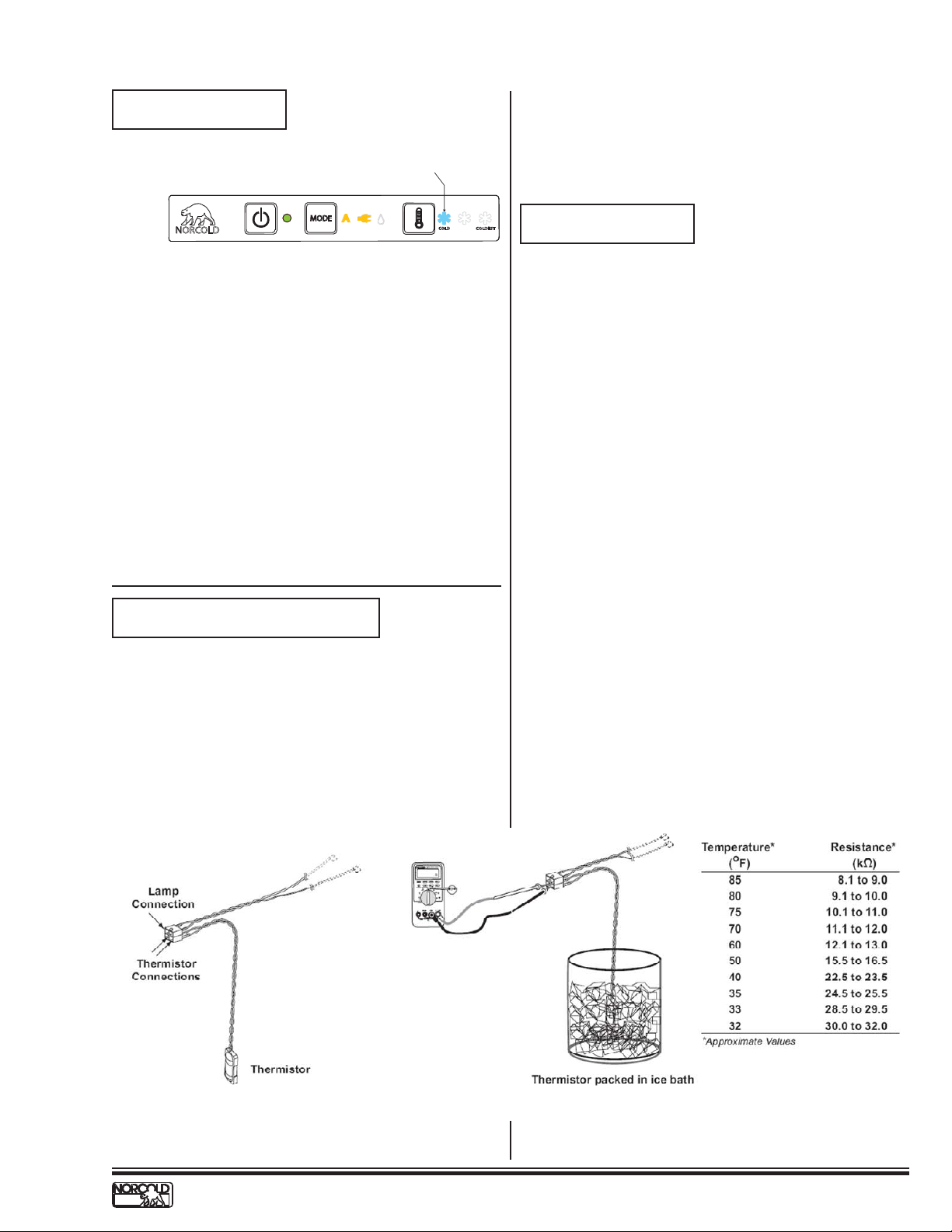
NX61 / NX81 Fault Codes - cont’d
Thermistor Fault
COLD indicator light(s) will flash OFF/ON at 1-second intervals (Only while control is “Awake”)
MODE
A
NORCOLD
NOR000122-10A
A
COLD
COLDEST
A fl ashing COLD temperature indicator (snowfl ake) means
the electronic controls have sensed the fi n thermistor to be
inoperable. This fault is only displayed while the optical display
is awake. To wake the optical display, press and release either
the Mode or Temp Set buttons. If a problem is sensed with
the thermistor the COLD temperature indicator (snowfl ake)
will fl ash ON and OFF. After 10-seconds the control will revert
back to the sleep mode. This fault can be displayed in ANY
MODE. Should the thermistor be sensed inoperable the
electronic controls will ignore the thermistor and revert to a
BOS mode (Backup Operating System). Refer to Backup
Operating System (BOS) Mode section of this manual-on
"Backup Operating System (BOS) Mode" on page 14.
Verify:
• The lamp-thermistor wire assembly is plugged in and
that the connections are not dirty or broken (see Fig.
5A).
• Thermistor resistance (see Fig. 5B).
is monitored by the optical display board and communicated
back to the power board which in turn activates the interior
light output accordingly. Because the switch operates via the
proximity of the magnet, it is important that the door alignment
is correct. To test for interior light operation, refer to Interior
Light Test on "Interior Light Test Procedure" on page 25.
Blank Display
On-Off Theory of Operation:
Continuous 12-Volts:
See Fig. 6.- page 21
12VDC is supplied to the refrigerator at Power Board terminals
12VDC & GND [A]. This 12VDC travels through the Power
Board to fuse F1 [B] and then out to P1-6 [C]. Via the green
wire, the 12VDC exits the Power Board and enters the Display
Board at P1-1 [D]. The 12VDC travels through the Display
Board to one side of the normally open On-Off switch [E]. This
12VDC is referred to as the continuous 12-volts because it
is always present at the one side of the On-Off switch when
12VDC power is applied to the refrigerator.
Switched 12-Volts:
See Fig. 7. - page 21
Door Fault
There is no displayed fault for an open door however; the
interior light will automatically be turned off in the event the
door has been sensed open for more than 2-minutes. The light
switch, a magnetically activated reed switch attached to the
optical display board, is activated by a magnet located beneath
the refrigerator doors top trim piece. When the magnet is
close to the reed switch (door closed) the light remains off;
when the magnet is away from the reed switch (door open) the
light is turned on. The open/closed status of the reed switch
Pressing the On-Off switch [E] will allow 12VDC to pass
through the On-Off switch and back to the Power Board via
the blue wire [F] connected between the Display Board at P1-3
and the Power Board at P2-3. Once the 12VDC reaches the
Power Board, a signal is sent out to the coil of relay K3 [G]
via the U1 microprocessor. This signal allows the K3 relay to
energize thus closing the normally open contacts [H].
Fig. 5A - Thermistor
Fig. 5B - Thermistor in Ice
www.norcold.com/cda
NX6 / NX8 / NXA ModelsRefrigerator Service Manual
19
 Loading...