

Norcold 982F, 9182F, 982-FIM, N821F, N820F Installation Instructions Manual
...
UPPER & LOWER SIDE
VENT INSTALLATION
FOR NORCOLD MODELS 900/9100/N600/N800
Read these important instructions carefully . Become thoroughly acquainted with the
content before installing vents and refrigerator.
IMPORT ANT NOTE: Norcold’ s
These
Ventilation and Installation
and Installation
codes, or in the absence of local codes, with these standards:
In the United States:
- National Fuel Gas Code, ANSI Z223.1.
- Manufactured Home construction and Safety Standard, Title 24 CFR, Part 32-80.
- Standard for Recreational Vehicles, ANSI A119.2 latest edition.
In Canada:
- Current CGA B149.1 and CGA B149.2 installation code for Propane Appliances and Equip-
- Current CSA Z240.4.2 Installation Requirement for Propane Appliances and Equipment in
- Current CSA Z240.6.2/C22.2 No. 148 Electrical Requirement for Recreational Vehicles.
Upper and Lower Side Vent Installation
instructions when installing the refrigerator. Installation must conform with local
ment.
Recreational Vehicles.
Venting and Installation
instructions are in addition to Norcold’s
instructions that accompany each refrigerator. Follow the
instructions must be followed.
Venting
When installed, the refrigerator must be electrically grounded in accord with local or state codes,
the National Electrical code, and ANSI/NFP A 70. In Canada, grounding is in accord with the
Canadian Electrical Code C22.2.
LP Gas supply piping and fittings must comply with local, state, and national codes governing type
and size. These components should also comply with the current NFP A 501C section 2.41, 1990
and with the current CAN 1-6.10 Standard.
Important!
During storage of the refrigerator in the RV or the trailer , always disconnect the power
source.
Part No. 618698C (7-98)
1
Upper and Lower Side V ent Installation
These instructions provide an alternative method for installing Norcold 6 and 8 cubic foot
refrigerators (see T able 1). This method allows for using two lower vents. The second lower vent
serves as the upper exhaust vent, replacing the roof vent. Use only those vents specified in the
refrigerator installation guide for side wall installation.
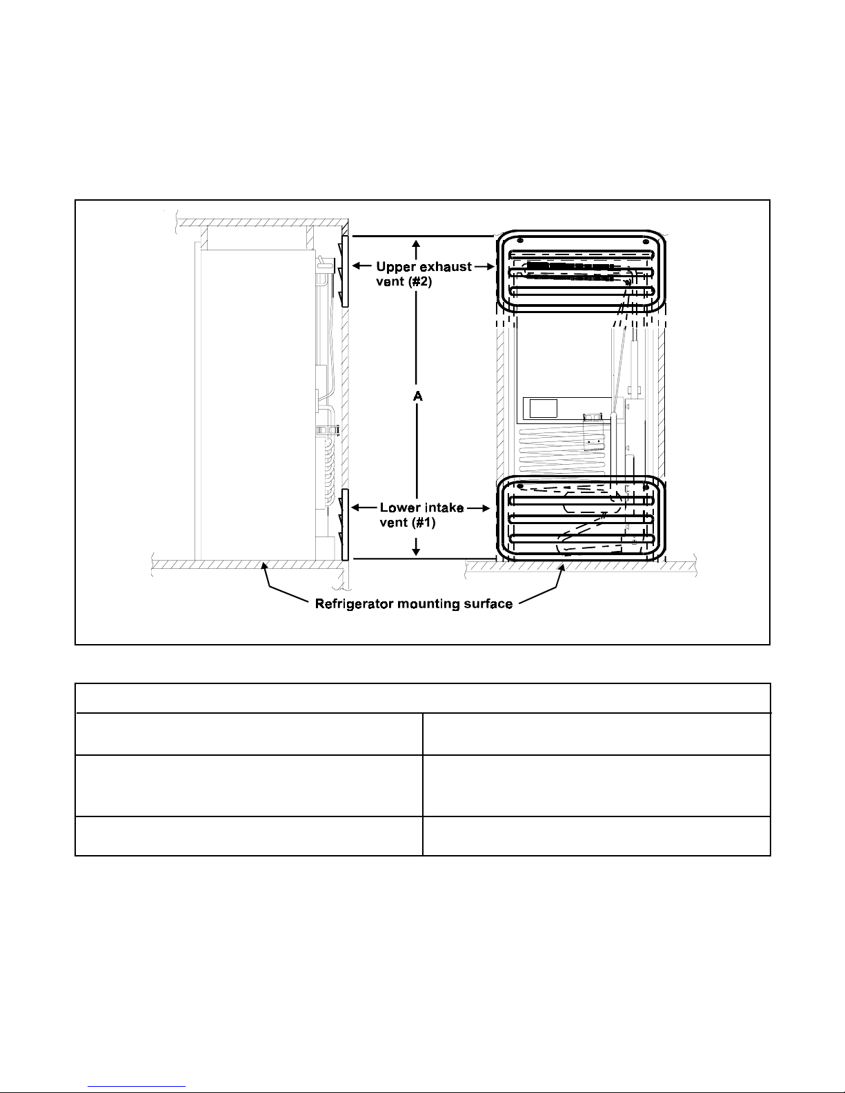
Side View Rear View
Figure 1
Refrigerator Models
8 Cubic Foot Models
982F , 9182F, 982-FIM, N820F, N821F
N841F , N841-FIM
A = 62” minimum
962F , 9162F, 962-FIM, N620F, N621F
6 Cubic Foot Models
N641F , N641-FIM
A = 55” minimum
Table 1
1. Install the lower intake vent flush with the refrigerator mounting surface (see Figure 1, #1). this
location provides the necessary ventilation from outside the vehicle.
2. Install the upper exhaust vent (see Figure 1, #2) directly above the lower vent at the A
dimension, (see Figure 1 and T able 1) for the model being installed. Position this vent directly
behind the cooling unit condenser to allow heat and exhaust from the cooling unit to vent to the
outside.
2
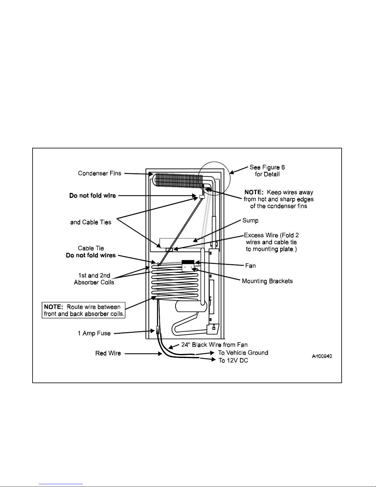
V entilation Fan Installation
T o ensure ef ficient performance, a continuous air flow is required across the refrigerator’s cooling
system. A thermostat controlled fan must attach to the refrigerator’s cooling system before
placing the refrigerator in the enclosure. This fan assists air flow across the cooling system. The
thermostat turns on the fan whenever the refrigerator’s cabinet temperature reaches 95 °
Fahrenheit. Even with the fan, the air flow from the side intake vent across the refrigerator’s
cooling system to the exhaust vent must be unobstructed.
Figure 2 shows the back of the refrigerator and the location of he 1st and 2nd absorber coils.
Also in Figure 2 are items installation and their approximate locations.
Mounting Plates
Figure 2
3
 Loading...