

Norcold N620, N640, N641, N621, N640-IM Service Manual
...
Service Manual
For models N620 and N621: 6 cu.ft., 2-way, R.V. refrigerators.
For models N640 and N641: 6 cu.ft., 2-way or 3-way, R.V. refrigerators.
For models N640-IM and N641-IM: 6 cu.ft., 2 way or 3-way , R.V. refrigerators with ice maker.
For models N820 and N821: 8 cu.ft., 2-way, R.V. refrigerators.
For models N840 and N841: 8 cu.ft., 2-way or 3-way, R.V. refrigerators.
For models N840-IM and N841-IM: 8 cu.ft., 2-way or 3-way, R.V. refrigerators with ice maker.
These model numbers are 2-way refrigerators. The model numbers of 3-way refrigerators
include “.3”.
NORCOLD, Inc.
P.O. Box 4248
Sidney, OH 45365-4248
Part No. 619394 (5-98)
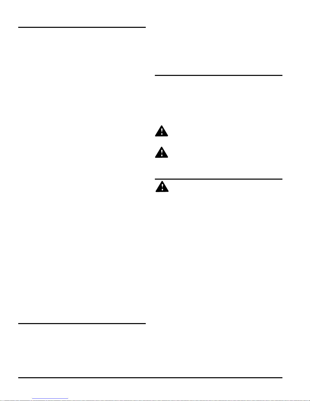
Table of Contents
Introduction ..............................................................................2
Safety Awareness .................................................................... 2
Safety Instructions ................................................................... 2
Specifications ..........................................................................3
Supply Voltage, Fuse, and Wire Size Requirements..............3
Operating Requirements ........................................................ 4
Heater Specifications .............................................................. 4
Other Current Draws ...............................................................4
Ventilation Requirements ........................................................ 5
Propane Gas Components ..................................................... 5
Examine the Gas Supply System for Leaks ....................5
Electrical Components ............................................................ 6
Operating the Refrigerator Controls (models N620, N621,
N820, and N821) .............................................................. 6
Operating the Refrigerator Controls (models N640, N641,
N640-IM, N641-IM, N840, N841,N840-IM,and N841-IM) . 8
Backup Operating System ...................................................... 9
Fault Codes (models N620, N621, N820, and N821) .......... 10
Fault Codes (models N640, N641, N640-IM, N641-IM, N840,.
N841,N840-IM,and N841-IM) ......................................... 11
Troubleshooting ....................................................................12
No Display on Display Panel ......................................... 12
Propane Gas ignition Failure ......................................... 13
Fresh Food Compartment Door Ajar ............................. 14
AC Power Not Available ................................................. 14
AC Voltage Too Low .......................................................15
AC Voltage Too High....................................................... 15
DC Voltage Too Low .......................................................15
DC Voltage Too High ...................................................... 16
AC Heater Output Failure ............................................... 16
DC Heater Output Failure .............................................. 16
DC Heater Failed Open ................................................. 17
AC Heater Failed Open .................................................. 17
Flame Sense Circuit Failure .......................................... 1 8
Back Up Operating System............................................ 1 8
Control Diagnostic Function (models N620, N621,
N820, and N821) ............................................................ 19
Control Diagnostic function (models N640, N641, N640-IM,
N641-IM, N840, N841,N840-IM,and N841-IM)...............2 0
Ice Maker (models N640-IM, N641-IM, N840-IM
and N841-IM).................................................................. 2 1
Ice Maker Specifications ................................................21
Common Problems and Solutions ............................... 2 2
Trouble Shooting ............................................................ 2 2
Ice Maker Does Not Make Ice ........................................ 23
Refrigerator Maintenance ...................................................... 2 4
Gas Flame Appearance ................................................. 2 4
Remove and Clean the Burner Orifice........................... 2 4
Diagnosing Cooling Problems ............................................. 2 4
Fuse Replacement ................................................................ 25
Remove the Refrigerator ....................................................... 2 5
Reinstall the Refrigerator ...................................................... 2 5
Wiring Pictorial ...................................................................... 26
Wiring Diagram ..................................................................... 2 6
Ice Maker Wiring Pictorial and Diagram (models N640-IM,
N641-IM, N840-IM and N841-IM) ...................................26
Introduction
This manual supplies information for the experienced repair
technician. The repair technician should have working
knowledge of the operation of an absorption refrigerator
system and should have basic knowledge of LP gas and
electrical systems.
If you are unable to resolve the problem using this Service
Manual, technical service support is available at 1-800-543-
1219.
Use only genuine Norcold replacement parts on the refrigera-
tor. Generic parts do not meet Norcold’s specifications for
reliability, performance and safety and will void the Norcold
Limited Warranty.
Safety Awareness
Read this manual carefully and understand the contents
before you install the refrigerator.
Be aware of possible safety hazards when you see the safety
alert symbol on the refrigerator and in this manual. A signal
word follows the safety alert symbol and identifies the danger
of the hazard. Carefully read the descriptions of these signal
words to fully know their meanings. They are for your safety.
WARNING: This signal word means a hazard, which
if ignored, can cause dangerous personal injury, death,
or much property damage.
CAUTION: This signal word means a hazard, which if
ignored, can cause small personal injury or much
property damage.
Safety Instructions
WARNING:
- This refrigerator is equipped for the use of propane gas
only and can not be changed to use any other fuels
(natural gas, butane, etc.).
- Incorrect installation, adjustment, alteration, or maintenance of this refrigerator can cause personal injury,
property damage, or both.
- Obey the instructions in the “Installation Manual” to
install the intake and exhaust vents.
- Do not install the refrigerator directly on carpet. Put the
refrigerator on a metal or wood panel that extends the
full width and depth of the refrigerator.
- Propane gas can ignite and cause a fire or an explosion that can result in property damage, personal
injury, or death. Do not smoke or create sparks while
doing any work on the propane gas supply system. Do
not use an open flame to examine the gas supply
piping or fittings for leaks.
- To avoid possible gas leaks, always use two wrenches
to tighten or loosen the gas supply line connections.
- Make sure the electrical installation obeys all applicable codes. See the “Certification and Code Requirements” section of the “Installation Manual”.
- Disconnect both the AC and DC power sources before
doing any maintenance work on the refrigerator.
Read the ”Installation Manual”, the “Owner’s Manual”, all
service procedures, cautions, and warnings before you do
any service work on the refrigerator.
Service Manual 2
- Do not bypass or change the refrigerator’s electrical
components or features.
- Do not spray liquids near electrical outlets, connections, or the refrigerator components. Many liquids are
electrically conductive and can cause a shock hazard
and in some cases fire.
- A circuit overload can result in an electrical fire if the
wires and/or fuse sizes used are not correct. Use only
the wire and fuse sizes written in the “Installation
Manual”
- The refrigerator cooling system is under pressure. Do
not try to repair or to recharge a defective cooling
system. The cooling system contains sodium chromate. The breathing of certain chromium compounds
can cause cancer. The cooling system contents can
cause severe skin and eye burns, and can ignite and
burn with an intense flame. Do not bend, drop, weld,
move, drill, puncture, or hit the cooling system.
- Do not remove the round ground prong from the
refrigerator AC power cord. Do not use a two prong
adapter or extension cord on the AC power cord.
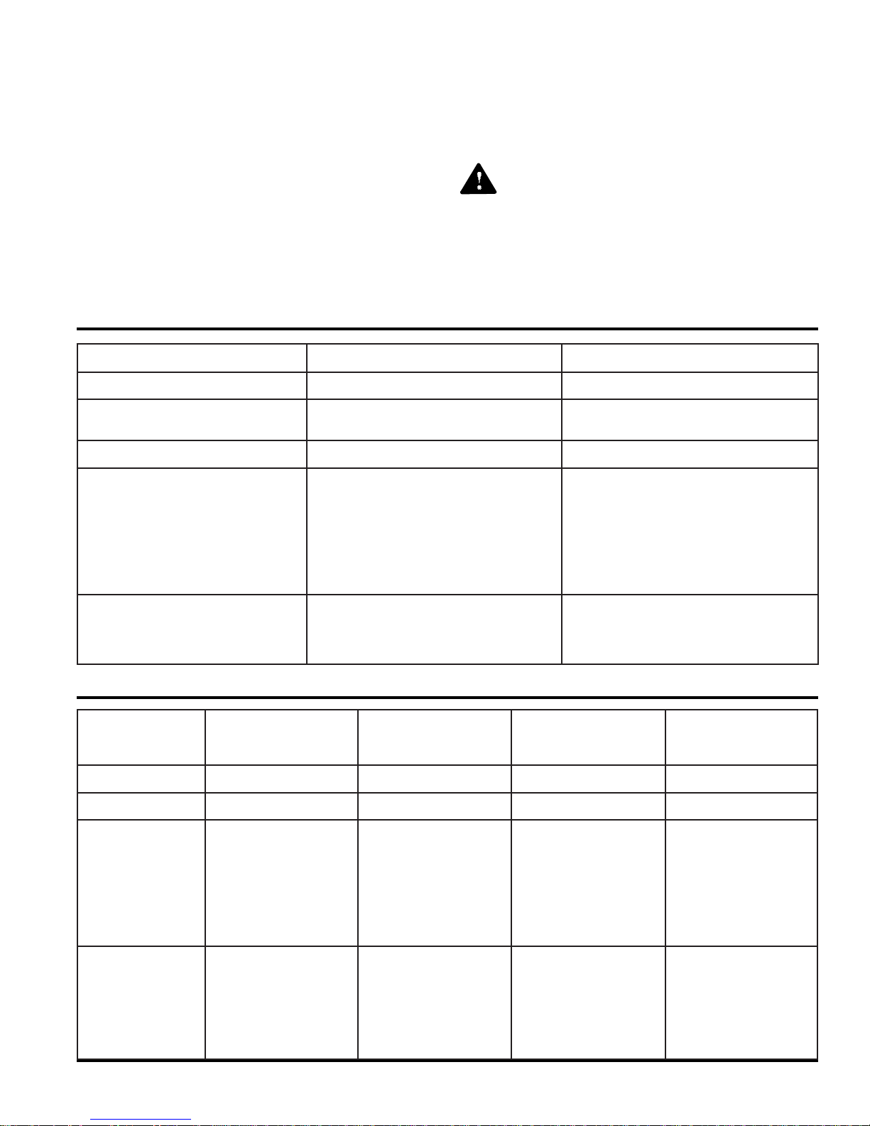
Specifications
50010trAsledoM__8NsledoM__6N
).tf.uc(emuloVegarotS5.73.6
).ni(gninepOhguoR
DxHxW
tiKtneVdeifitreC3#tiK3#tiK
gnitneVdeifitreC
noitallatsnIdna
- To prevent child entrapment, make sure all shelf
retainers are correctly fastened and remove the doors
before disposing of the refrigerator.
CAUTION:
- The rear of the refrigerator has sharp edges and
corners. To prevent cuts or abrasions when working
on the refrigerator, use caution and wear cut resistant
gloves.
- Make sure all fasteners and connections are tight.
42x8/795x2/13242x8/725x2/132
.egnahctuohitwdellatsnitiktneV-
.metsys
gniloochguorhtwolfriadetcurtsbonU-
).sni(secnaraelC-
4/1-0poT
2/1-0sediS
1-0raeR
0mottoB
.metsys
).sni(secnaraelC-
4/1-0poT
2/1-0sediS
1-0raeR
0mottoB
.egnahctuohitwdellatsnitiktneV-
gniloochguorhtwolfriadetcurtsbonU-
seziSlenaProoDevitaroceD
.ni61/3-ssenkcihT
).ni(WxHrooDreppU
).ni(WxHrooDrewoL
Supply Voltage, Fuse, and Wire Size Requirements
60010trA
egatloVylppuSCD.xam4.51-.nim5.01.xam4.51-.nim5.01.xam4.51-.nim5.01.xam4.51-.nim5.01
egatloVylppuSCA.xam231-.nim801.xam231-.nim801.xam231-.nim801.xam231-.nim801
fosesuflanretnI
rotaregirfeR
eriWylppuSCD
seziSesuFdna
morfecnatsidehtfI(
ehtotyrettabeht
:sirotaregirfer
sselro.tf02*
).tf02nahterom**
,028NsledoM
,048N,128N
MI048Ndna
:egatlovlortnoCCD
epytedalbpmA3
:tiucriCCA
)ssalg(GA3pmA5
.nimGWA81*
.xamGWA81**
esufpmA6*
esufpmA6**
,3.028NsledoM
,3.048N,3.128N
MI3.048Ndna
epytedalbpmA3
:tiucriCCA
.nimGWA01*
.xamGWA8**
esufpmA03*
esufpmA04**
23/9112x23/7141
23/9112x8/583
,026NsledoM
,046N,126N
MI046Ndna
:egatlovlortnoCCD
:egatlovlortnoCCD
epytedalbpmA3
)ssalg(GA3pmA5
:)retaeh(cirtcelECD
epytedalbpmA03
:tiucriCCA
)ssalg(GA3pmA5
.nimGWA81*
.xamGWA81**
esufpmA6*
esufpmA6**
23/9112x23/7141
23/9112x8/513
,3.026NsledoM
,3.046N,3.126N
MI3.046Ndna
:egatlovlortnoCCD
epytedalbpmA3
:tiucriCCA
)ssalg(GA3pmA5
:)retaeh(cirtcelECD
epytedalbpmA03
.nimGWA01*
.xamGWA8**
esufpmA03*
esufpmA04**
Service Manual 3
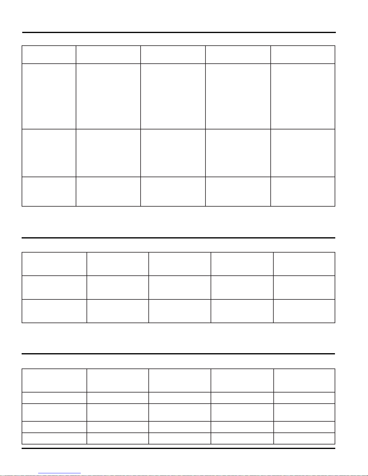
Operating Requirements
70010trA
ecifirO5510.
saGenaporP
noitarepO
stnemeriuqeR
cirtcelECA
noitarepO
stnemeriuqeR
cirtcelECD
noitarepO
stnemeriuqeR
.tiucric
.retaeh
.retaehCA
,128N,028NsledoM
MI048Ndna,048N
ecifirO5510.
gnitareporofCDV21,thgilroiretni,slortnoc
noitcudererutsiom
noitingisagdnaretaeh
.tiucric
ylppustasagenaporP.C.W.ni11foerusserp
gnitareporofCDV21-
,thgilroiretni,slortnoc
noitcudererutsiomdna
.retaeh
rofztreH06,CAV021-
.retaehCA
gnitareporofCDV21-
dna,thgilroiretni,slortnoc
.retaehnoitcudererutsiom
.retaehCDdna
,3.128N,3.028NsledoM
MI3.048Ndna,3.048N
ecifirO510.
gnitareporofCDV21-
,thgilroiretni,slortnoc
noitcudererutsiom
noitingisagdnaretaeh
.tiucric
ylppustasagenaporP.C.W.ni11foerusserp
gnitareporofCDV21-
,thgilroiretni,slortnoc
noitcudererutsiomdna
.retaeh
rofztreH06,CAV021-
.retaehCA
gnitareporofCDV21-
,thgilroiretni,slortnoc
,retaehnoitcudererutsiom
,126N,026NsledoM
MI046Ndna,046N
ecifirO510.
gnitareporofCDV21,thgilroiretni,slortnoc
noitcudererutsiom
noitingisagdnaretaeh
.tiucric
ylppustasagenaporP.C.W.ni11foerusserp
gnitareporofCDV21-
,thgilroiretni,slortnoc
noitcudererutsiomdna
.retaeh
rofztreH06,CAV021-
.retaehCA
gnitareporofCDV21-
dna,thgilroiretni,slortnoc
.retaehnoitcudererutsiom
.retaeh.CDdna
,3.126N,3.026NsledoM
MI3.046Ndna,3.046N
gnitareporofCDV21,thgilroiretni,slortnoc
noitcudererutsiom
noitingisagdnaretaeh
ylppustasagenaporP.C.W.ni11foerusserp
gnitareporofCDV21-
,thgilroiretni,slortnoc
noitcudererutsiomdna
rofztreH06,CAV021-
gnitareporofCDV21-
,thgilroiretni,slortnoc
,retaehnoitcudererutsiom
Heater Specifications
80010trA
retaeHCA
smhO/spmA/sttaW
)%5-/+gnidaersmhO(
retaeHCD
smhO/spmA/sttaW
)%5-/+gnidaersmhO(
Other Current Draws
90010trA
noitingIcitamotuApmA05.pmA05.pmA05.pmA05.
,128N,028NsledoM
MI048Ndna,048N
3.04/7.2/0033.04/7.2/0033.04/7.2/0033.04/7.2/003
,128N,028NsledoM
MI048Ndna,048N
,3.028NsledoM
dna,3.048N,3.128N
MI3.048N
78./61/52278./61/522
,3.028NsledoM
dna,3.048N,3.128N
MI3.048N
,126N,026NsledoM
MI046Ndna,046N
,126N,026NsledoM
MI046Ndna,046N
,3.026NsledoM
dna,3.046N,3.126N
MI3.046N
,3.026NsledoM
dna,3.046N,3.126N
MI3.046N
noitcudeRerutsioM
retaeH
thgiLroiretnIpmA06.pmA06.pmA06.pmA06.
evlaVsaGpmA41.pmA41.pmA41.pmA41.
Service Manual 4
pmA71.ot11.pmA71.ot11.pmA71.ot11.pmA71.ot11.
V entilation Requirements
Propane Gas Components
WARNING: The completed installation must:
- Make sure there is sufficient intake of fresh air for
combustion.
- Make sure the living space is completely isolated
from the combustion system of the refrigerator.
- Make sure there is complete and unrestricted
ventilation of the flue exhaust which, in gas mode,
can produce carbon monoxide. The breathing of
carbon monoxide fumes can cause dizziness,
nausea, or in extreme cases, death.
Certified installation needs one lower intake vent and one
upper exhaust vent. Install the vents exactly as instructed in
the “Installation Manual”. Any other installation method voids
both the certification and the factory warranty of the refrigerator.
The bottom of the opening for the lower intake vent, which is
also the service access door, must be even with or immediately below the floor level. This allows any leaking LP gas to
escape to the outside and not to collect at floor level.
If the vehicle has two side wall vents, the minimum distance
from the floor level to the top of the upper exhaust vent is 55
inches on N6__ models and 62 inches on N8 __ models.
This refrigerator operates on propane gas at a pressure of
10.5 inches Water Column min. to 11.5 inches Water Column
max.
WARNING: Be very careful when working on or near
the propane gas system.
- Do not smoke, or use an open flame near the
propane gas system.
- Do not use an open flame to examine for leaks.
- Do not connect the refrigerator to the propane gas
tank without a pressure regulator between them.
- To avoid possible propane gas leaks, always use
two wrenches to tighten or loosen the gas supply
line connections.
- Leaking propane gas can ignite or explode and
result in dangerous personal injury or death.
Examine the gas supply system for leaks:
WARNING: Do not allow the leak detecting solution to
touch the electrical components. Many liquids are
electrically conductive and can cause a shock hazard,
electrical shorts, and in some cases fire.
American Gas Association/Canadian Gas Association (AGA/
CGA) certification allows the refrigerator to have zero (0) inch
minimum clearance at the sides, rear, top, and bottom. While
there are no maximum clearances specified for certification,
the following maximum clearances are necessary for correct
refrigeration:
Bottom 0 inch min. 0 inch max.
Each Side 0 inch min 1/2 inch max.
Top 0 inch min. 1/4 inch max.
Rear 0 inch min. 1 inch max.
These clearances plus the lower and upper vents cause the
natural air draft that is necessary for good refrigeration.
Cooler air goes in through the lower intake vent, goes around
the refrigerator coils where it removes the excess heat from
the refrigerator components, and goes out through the upper
exhaust vent. If this air flow is blocked or decreased, the
refrigerator may not cool correctly.
Each NORCOLD model is certified by AGA and CGA for
correct ventilation.
Using a solution of liquid detergent and water, make sure the
gas supply line and all gas connections have no leaks. Do
not use any liquid that contains ammonia.
If you use compressed air for the test:
- The pressure of the compressed air at the manual
shutoff valve of the refrigerator must not be more than 1/2
psig (14 inches Water Column).
- If the pressure of the compressed air is more than 1/2
psig (14 inches Water Column), remove the gas supply
line from the manual shutoff valve of the refrigerator
before the test.
- If the pressure of the compressed air is equal to or less
than 1/2 psig (14 inches Water Column), close the
manual shutoff valve of the refrigerator before the test.
Service Manual 5
Electrical Components
This refrigerator operates on these electrical sources.
AC Operation 120 volts AC voltage
(108 volts min. - 132 volts max.)
12 volts DC control voltage
(10.5 volts min. - 15.4 volts max.)
DC Operation 12 volts DC voltage
(3-way models) (10.5 volts min. - 15.4 volts max.)
Operation out of these limits may damage the refrigerator’s
electrical circuit parts and will void the warranty.
Examine the 120 volts AC supply:
WARNING: Connect the AC power cord only to a
grounded three-prong receptacle. Do not remove the
round ground prong from the power cord. Do not use a
two-prong adapter or an extension cord. Operation of
the refrigerator without a correct ground could cause
dangerous electrical shock or death if you are touching
the metal parts of the refrigerator or the vehicle.
- Make sure the AC power cord is in a grounded threeprong receptacle.
- Make sure the positive DC wire from the battery is
connected to the power board terminal that is marked
12VDC.
- Make sure the DC ground wire from the battery is
connected to the power board terminal that is marked
12V GND1.
- Make sure each DC power supply wire is on the correct
polarity terminal.
- Make sure an in-line fuse is installed on the DC positive
wire, as near the battery as possible, between the battery
and the terminal block of the refrigerator.
NOTE: This in-line fuse is necessary for added safety, even
though the refrigerator has a DC fuse in the control
assembly.
Operating the Refrigerator Controls
(models N620, N621, N820, and N821)
Control panel:
- Make sure the receptacle is within easy reach of the lower
intake vent.
- Make sure the power cord does not touch the burner
cover, the flue pipe, or any hot component that could
damage the insulation of the power cord.
Examine the 12 volt DC supply:
The refrigerator gets power from the 12 volt system of the
vehicle; either from the battery or from an auxiliary (house)
battery. The battery system not only supplies DC power to the
refrigerator, but also to other components of the vehicle.
The DC heating element, which supplies power for cooling
during DC operation, has a high current draw and can cause
rapid battery drain.
Make sure the wire size and fuse size are correct:
- On 2-way models, use a minimum of 18 AWG wire and a
maximum 6 Amp fuse.
- On 3-way models, measure the distance from the vehicle
battery to the refrigerator.
- If the distance is 0 - 20 feet, use a minimum of 10
AWG wire and a 30 Amp fuse.
- If the distance is over 20 feet, use a minimum of 8
AWG wire and a maximum 40 Amp fuse.
- If the wire size is larger than the min. size, use the correct
fuse per RVIA A119.2 standard or local codes.
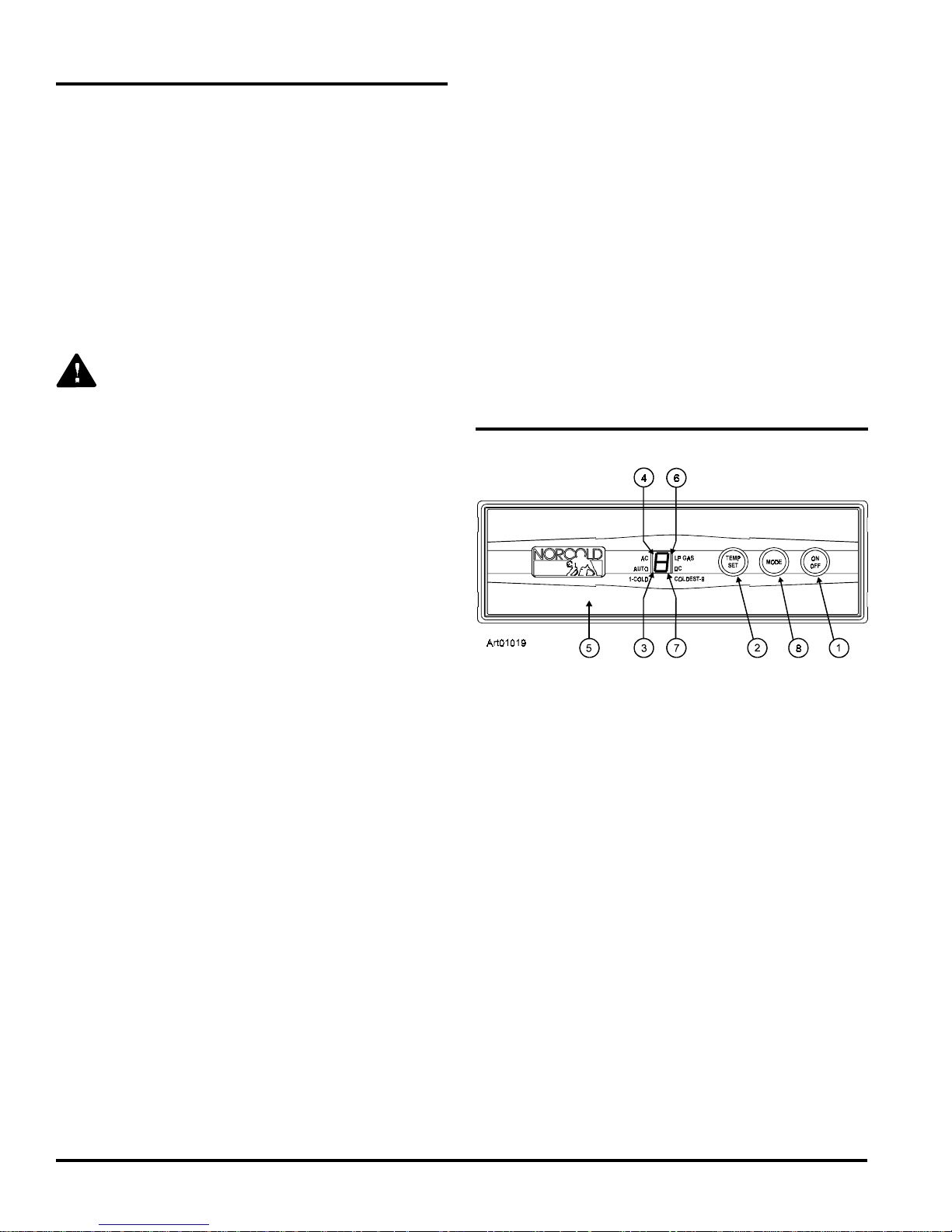
The refrigerator control panel (see Art01019) is between the
freezer compartment and the fresh food compartment. To
maintain the operating control functions of the refrigerator, a
12 volt DC power supply is necessary. The refrigerator and
any other DC components in the vehicle, receive DC power
from the 12 volt system of the vehicle; either an auxiliary
battery, a converter, or the vehicle engine battery.
The ON / OFF button [1] starts and shuts down the refrigerator:
- If the refrigerator is shut down, press the ON / OFF button
to start the refrigerator in auto mode.
- If the refrigerator is operating, press and hold the ON /
OFF button for two seconds to shut down the refrigerator.
The TEMP SET button [2] controls the temperature adjustment of the freezer and the fresh food compartment. The
temperature adjustment that you select does not change if
the mode of operation of the refrigerator changes.
- Push the TEMP SET button and the temperature setting
“1-9” appears in the center display [3].
- Push and hold the TEMP SET button and the temperature
setting changes.
Service Manual 6
- The number “9” is the coldest temperature setting.

The MODE button [8] controls the operation mode of the
refrigerator.
- Push and hold the MODE button and a light bar flashes in
the center display beside each of the four operating
modes of the refrigerator, one at a time.
- There is one automatic mode of operation and three
manual modes of operation.
- When the light bar flashes beside the mode of
operation that you wish, release the MODE button.
Manual mode operation:
When you select one of the manual modes of operation, The
light bar beside the AUTO goes out in the center display and
only the light bar beside either AC, LP GAS, or DC remains.
- AC means that the refrigerator is operating on AC electric.
- LP GAS means that the refrigerator is operating on
propane gas.
If the energy source is interrupted:
Automatic mode operation:
When you select AUTO mode, the refrigerator controls
automatically select the most efficient energy source that is
available for operation. If a more efficient energy source
becomes available, the refrigerator controls change from the
current energy source to the more efficient energy source.
The controls select the energy source in this sequence:
- When 120 volts AC is available to the refrigerator:
- The light bars beside AUTO [3] and AC [4] show in
the center display.
- After ten seconds, the light bar beside AC goes off
and only the light bar beside AUTO remains.
- This means that the refrigerator is operating on AC
electric.
- If 120 volts AC is not available to the refrigerator:
- The light bars beside AUTO and LP GAS [6] show in
the center display.
- After ten seconds, the light bar beside LP GAS goes
off and only the light bar beside AUTO remains.
- The refrigerator stops operation.
- Refer to the “Fault Codes” section of this manual.
Ignition of LP gas in either auto or manual mode:
NOTE: On initial start up of the refrigerator, ignition of the
propane gas may not occur within 30 seconds.
If ignition of the propane gas does not occur within 30
seconds:
- The gas safety valve of the refrigerator closes.
- The refrigerator stops operation.
- Refer to the “Fault Codes“ section of this manual.
- The fault code remains until you push the ON / OFF
button two times (to stop and start the refrigerator).
- If ignition does not occur after two or three times:
- Check the gas supply line.
- Refer to the “Gas Ignition Fault” chart that is in the
“Troubleshooting” section this manual.
- This means that the refrigerator is operating on
propane gas.
If an energy source is available to the refrigerator, but is not
operating correctly:
- A fault code appears in the center display.
- The refrigerator controls try to change to a less efficient
energy source.
- If a less efficient energy source is not available:
- The refrigerator stops operation.
- Refer to the “Fault Codes” section of this manual.
Service Manual 7
Operating the Refrigerator Controls
(models N640, N641, N640-IM, N641-IM,
N840, N841, N840-IM, and N841-IM)
Control panel:
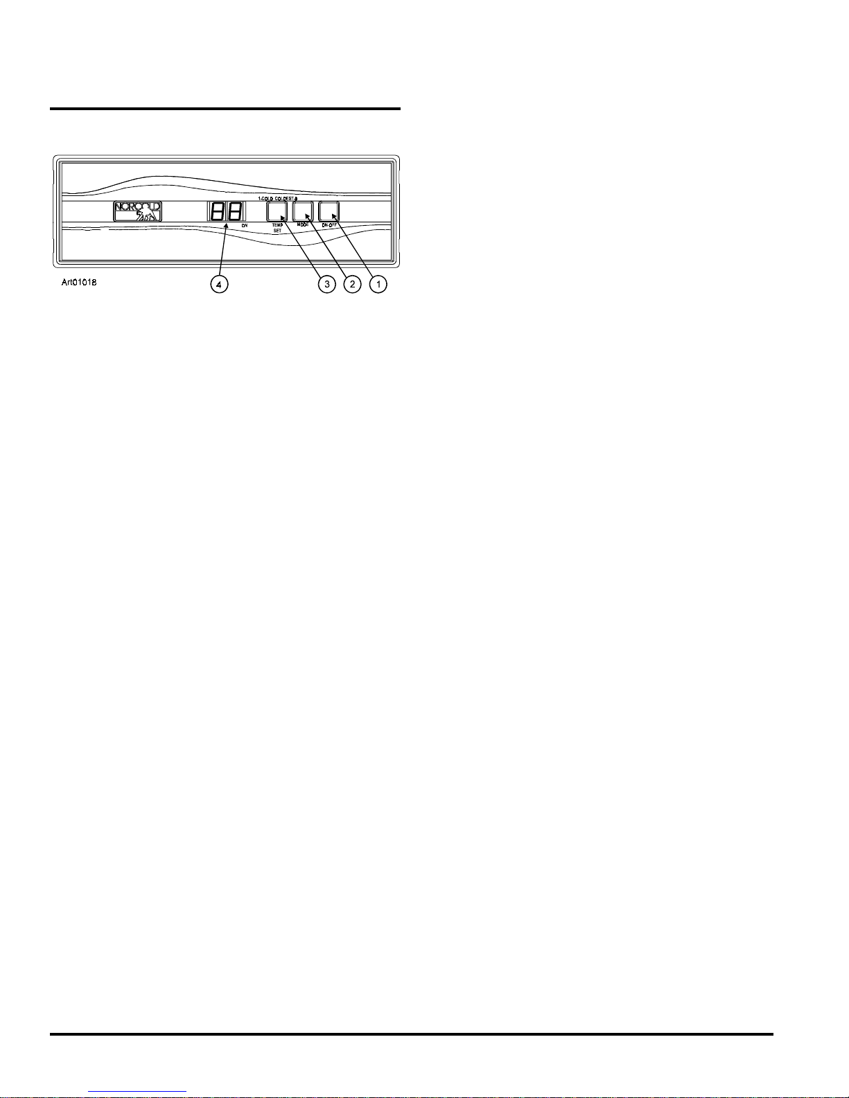
The refrigerator control panel (See Art01018) is between the
freezer compartment and the fresh food compartment. To
maintain the operating control functions of the refrigerator, a
12 volt DC power supply is necessary. The refrigerator and
any other DC components in the vehicle, receive DC power
from the 12 volt system of the vehicle; either an auxiliary
battery, a converter, or the vehicle engine battery.
Automatic mode operation:
When you select AUTO mode, the refrigerator controls
automatically select the most efficient energy source that is
available for operation. If a more efficient energy source
becomes available, the refrigerator controls change from the
current energy source to the more efficient energy source.
The controls select the energy source in this sequence:
- When 120 volts AC is available to the refrigerator:
- “AU” “AC” flashes in the center display.
- This means that the refrigerator is operating on AC
electric.
- After ten seconds, the “AU” “AC” goes off and only a
power indicator remains.
- If 120 volts AC is not available to the refrigerator:
- “AU” “LP” flashes in the center display.
- This means that the refrigerator is operating on
propane gas.
The ON / OFF button [1] starts and shuts down the refrigerator:
- If the refrigerator is shut down, push the ON / OFF button
to start the refrigerator in auto mode.
- If the refrigerator is operating, push and hold the ON /
OFF button for two seconds to shut down the refrigerator.
The TEMP SET button [3] controls the temperature adjustment of the freezer and the fresh food compartment. The
temperature adjustment that you select does not change if
the operation mode of the refrigerator changes.
- Push the TEMP SET button and the temperature setting
“1-9” appears in the center display [4].
- Push and hold the TEMP SET button and the temperature
setting changes.
- The number “9” is the coldest temperature setting.
The MODE button [2] controls the operation mode of the
refrigerator:
- Push and hold the MODE button and each of the four
operating modes of the refrigerator flash one at a time in
the center display.
- There is one automatic mode of operation and there
are three manual modes of operation.
- On 3-Way models only, if neither 120 volts AC nor
propane gas is available to the refrigerator:
- “AU” “dc” flashes in the center display.
- This means that the refrigerator is operating on DC
electric.
NOTE: DC electric operation is less efficient than AC
electric and propane gas. Use DC electric
operation only to maintain the refrigerator
temperature while in transit and if the other
energy sources are not available. Do not use
DC electric to initially decrease the temperature of the refrigerator.
If an energy source is available to the refrigerator, but is not
operating correctly:
- A fault code shows in the center display.
- The refrigerator controls try to change to a less efficient
energy source.
- If a less efficient energy source is not available:
- An audible alarm starts.
- The refrigerator stops operation.
- Refer to the “Fault Codes” section of this manual.
- When the mode of operation that you wish shows in
the center display, release the MODE button.
Service Manual 8

Manual mode operation:
When you select one of the three manual modes, “AU” goes
out in the center display and either “AC”, “LP”, or “dc” appears.
- “AC” means that the refrigerator is operating on AC
electric.
- “LP” means that the refrigerator is operating on propane
gas.
- “dc” means that the refrigerator is operating on DC
electric.
If the energy source is interrupted:
- An audible alarm starts.
- The refrigerator stops operation.
- Refer to the “Fault Codes” section of this manual.
Backup Operating System
This refrigerator has a backup operating system. The backup
operating system allows the refrigerator to continue to cool if
the temperature sensor of the refrigerator should fail.
If this failure occurs:
- The refrigerator automatically changes to the backup
operating system.
- When you push the TEMP SET button, the temperature setting flashes in the center display for ten
seconds.
- After the temperature setting flashes, the mode of
operation appears in the center display.
- The backup operating system can over freeze or thaw the
contents of the freezer and the fresh food compartment.
Ignition of propane gas in either auto or manual
mode:
NOTE: On initial start up of the refrigerator, ignition of the
propane gas may not occur within 30 seconds.
If ignition of the propane gas does not occur within 30
seconds:
- The gas safety valve of the refrigerator closes.
- In the Auto mode:
- The refrigerator control changes to a less efficient
energy source (3-way models only).
- The fault code “no” “FL” shows in the center display
(2-way models only).
- In the Manual mode and operating on propane gas:
- An audible alarm starts.
- The fault code “no” “FL” shows in the center display.
- The audible alarm and the fault code remain until you
push the MODE button.
- Push the ON/OFF button two times to stop and start
the refrigerator.
- Make sure the temperatures of the freezer and the
fresh food compartment are satisfactory.
NOTE: If you open the door(s) too often, the tempera-
tures inside the freezer and fresh food
compartment do not become stable. Allow the
refrigerator to operate for about one hour after
each adjustment change before you examine
the contents. The number “9” is the coldest
temperature setting.
- If the temperature is too warm, push and hold
the TEMP SET button to raise the temperature
setting by one number.
- If the temperature is too cold, push and hold the
TEMP SET button to lower the temperature
setting by one number.
- The owner should have the refrigerator serviced by a
dealer or an Norcold authorized Service Center as soon
as possible.
- If ignition does not occur after two or three times:
- Check the gas supply line.
- Refer to the “Propane Gas Ignition Fault” chart that is
in the “Troubleshooting” section this manual.
Service Manual 9
 Loading...