

Norcold N611V, N811V Service Manual
Service Manual
!
Gas / Electric Refrigerators
MODELS
N611v Series
N811v Series
WARNING
DO NOT install this refrigerator in below deck marine applications. Do not
install this refrigerator in fi xed indoor cabin or other dwelling applications. This
refrigerator must use only NORCOLD designed and approved outside air intake
and exhaust ventilation for correct and safe operation. Any other ventilation
could cause lethal combustion exhaust fumes and/or explosive propane gas
fumes to be in the living area and/or below deck.
Questions?/Des questions?/¿Preguntas? 1-800-444-7210
© 2013 NORCOLD, INC. All rights reserved.
Publication No. 636355 A (15-01-2014)
CONTENTS
Introduction ..................................................................................................3
About this Manual ...................................................................................3
Model Identification .................................................................................3
Information Label ....................................................................................3
Certification and Code Requirements .....................................................3
About Installation ....................................................................................3
Replacement Parts .................................................................................3
T echnical Assistance ...............................................................................3
Model Identifi cation .....................................................................................4
Cooling Unit Serial Number ....................................................................4
Safety Awareness ........................................................................................5
Safety Notice ...........................................................................................5
Attention Statements ...............................................................................5
Safety Statements ...................................................................................5
Specifi cations ..............................................................................................6
Theory of Operation ....................................................................................7
Overview .................................................................................................7
Cooling Unit ............................................................................................7
Leveled Operation ...................................................................................7
Gradual Decrease in Cooling Efficiency .................................................7
Gas Absorption System .......................................................................... 8
Electronic Controls ..................................................................................9
Theory of Operation - Auto Modes ........................................................9
Background Operations ........................................................................10
Fault Codes ............................................................................................... 12
Diagnostic Prechecks ...........................................................................13
Fault Code Flash Patterns ....................................................................13
Solid Red Indicator Light ................................................................13
Fault / Flash Pattern 2 Service Error ..............................................14
Fault / Flash Pattern 3 Open High Limit .........................................14
Fault / Flash Pattern 4 AC Relay Error ........................................... 14
Fault / Flash Pattern 5 Flame On, Should Not Be On ....................14
Fault / Flash Pattern 8 LOW DC (1) Error ......................................15
Fault / Flash Pattern 9 LOW DC (2) Error ......................................15
Thermister Fault .............................................................................15
Door Fault .......................................................................................15
Blank Display ..................................................................................16
LP Gas System .........................................................................................18
Pressure Requirements ........................................................................18
Testing for LP Gas Leaks ......................................................................18
Components ..........................................................................................19
Flame Appearance ................................................................................ 20
Burner Cleaning Procedure ..................................................................21
Gas Lockout ..........................................................................................23
Reset a Gas Lockout Condition - All Models ......................................... 23
Gas Safety Valve Test ........................................................................... 23
Electrical Requirements and Components ................................................ 24
DC Voltage Requirements and Polarity ................................................24
DC Power Wiring Requirements ........................................................... 24
AC/DC Converter as Power Source ......................................................24
12VDC Ventilation Fan .......................................................................... 24
Cooling Unit ...............................................................................................26
Cooling System Monitoring ................................................................... 26
Troubleshooting Cooling Faults ............................................................26
Refrigerant Leakage .............................................................................26
Disposal of Cooling Unit ........................................................................26
Cooling System Diagnostic Flowchart ..................................................27
Wiring Pictorial ..................................................................................... 29
Modes Of Operation .................................................................................. 30
Refrigerator Start-Up .............................................................................30
Refrigerator Shut-Down ........................................................................30
Effects of High Altitude on Propane Gas Operation ..............................30
Effects of Freezing Temperatures on Refrigerator Operation ...............30
Figures
Fig. 1 - Refrigerator Information Label Location .............................. 4
Fig. 2 - Cooling Unit Bar Code Label Location. ................................4
Fig. 3 - Gas Absorption System ........................................................8
Fig. 4 - Flash Patterns ....................................................................13
Fig. 5A - Thermistor .......................................................................16
Fig. 5B - Thermistor in Ice ..............................................................16
Fig. 6 - Continuous 12-Volt ............................................................17
Fig. 7 - Switch 12-Volt ....................................................................17
Fig. 8 - LP Gas System Components. ............................................ 18
Fig. 9 - Solenoid Gas Valve. ...........................................................19
Fig. 10 - LP15 Orifice Assemblies ..................................................19
Fig. 11 - Burner ...............................................................................19
Fig. 12 - Burner Tube ......................................................................19
Fig. 13 - Flue and Components ...................................................... 20
Fig. 14 - Flue Baffle ........................................................................20
Fig. 15 - Flame Appearance ........................................................... 20
Fig. 16 - Drip Cup and Burner Box Cover .......................................22
Fig. 17 - Burner and Components .................................................22
Fig. 18 - AC Power Cord. ................................................................25
Fig. 19 - Fan Mounted on Top of Absorber Coil. ............................. 25
Fig. 20 - Fan Thermostat. ............................................................... 25
Fig. 21 - Fan with Installed NORCOLD Fan Kit. ............................. 25
Fig. 22 - NORCOLD Fan Kit Wiring Pictorial. ................................ 25
Fig. 23 - Reset Pushbutton .............................................................26
Fig. 24 - Cooling System Diagnostics .............................................27
Fig. 25 - Wiring ..............................................................................29
Fig. 26 - Wiring ..............................................................................29
2
www.norcold.com/cda
Refrigerator Service ManualN611v, N811v Models
INTRODUCTION
About this Manual
This service manual provides maintenance, diagnostic, and
repair information for NORCOLD
gas absorption refrigerators. It is a reference tool designed
for technicians who are knowledgeable in the theory and
operation of gas/electric absorption refrigerators, liquefi ed
petroleum (LP) gas–propane–systems, and AC/DC electrical
systems as installed in a variety of recreational vehicles (RV).
All information, illustrations, and specifi cations contained in
this publication are based on the latest product information
available at the time of publication. NORCOLD
right to make changes at any time without notice.
®
models N611v, N811v
®
reserves the
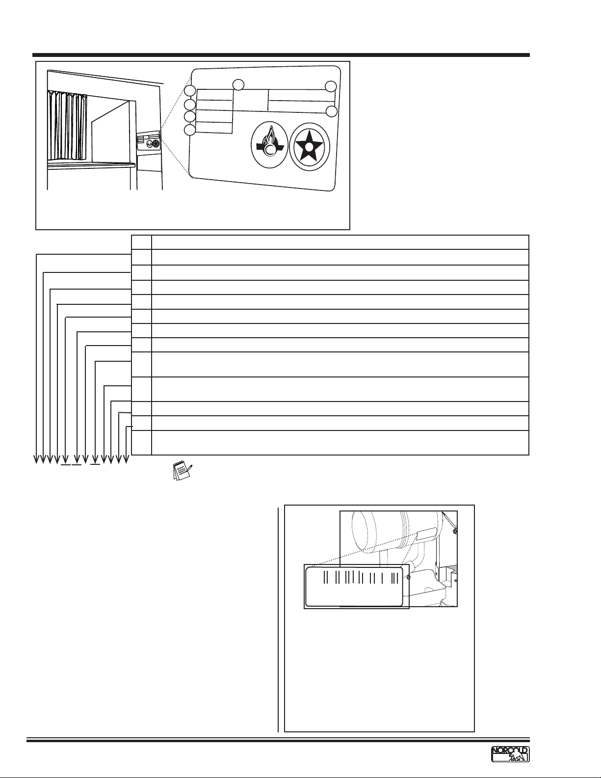
Model Identifi cation
Models N611v and N811v are 2-way refrigerators that operate
on AC power or LP gas.
Letter(s) appended to the model number identify factory
installed accessories. See Fig. 1.
Information Label
The information label is located in the upper right corner of the
fresh food compartment just below the divider. See Fig. 1. The
label provides the following information:
• Serial number.
• Model number.
• LP gas (propane) pressure.
• Btu/h.
• AC voltage and amperage.
• DC voltage and amperage.
• Design certifi cation.
• Vent kit requirement.
Certifi cation and Code Requirements
NORCOLD® N611v, N811v gas/electric absorption refrigerators
are certifi ed under the latest edition of ANSI Z21.19B
standards for installation in mobile homes or recreational
vehicles, and with the Canadian Standards Association CAN/
CGA-1.4-M94.
Electrical components are
compliant.
About Installation
Refrigerator installation must conform with the N611v, N811v
Installation Manual for the NORCOLD
in effect. Installation must also comply with applicable local
codes and standards set by the relevant certifi cation agency.
®
limited warranty to be
Replacement Parts
Use only authorized NORCOLD® replacement parts.
Generic parts do not meet NORCOLD
safety, reliability, and performance. The use of unauthorized
aftermarket or generic replacement parts voids the
refrigerator's limited warranty coverage.
®
specifi cations for
T echnical Assistance
If unable to resolve technical issues using the information
provided in this manual, technical support is available through
NORCOLD
The following information is required to process technical
support requests; refer to the following page:
• Refrigerator Model Number
• Refrigerator Serial Number
• Refrigerator Cooling Unit Serial Number
• Recreational Vehicle (RV) Make/Model/Year
®
Customer Service Center:
Telephone: 1-800-444-7210.
Fax: 1-734-769-2332
World Wide Web: www.norcold.com.
www.norcold.com/cda
N611v, N811v ModelsRefrigerator Service Manual
3
MODEL IDENTIFICATION
xxxxxxxxxxxxxxxxxxxxxxxxxxx
xxxxxxxxxxxxxxxxxxxxxxxxxxx
ORC
N
xxxxxxxxxxxxxxxxxxxxxx
xxxxxxxxxxxxxxxxxxxxx
xxxxxxxxxxxxxxxxxxxxx
xxxxxxxxxxxxxxxxxxx
xxxxxxxxxxxxxxxxxxxx
xxxxxxxxxxxxxxxxxxxxxxxxx
xxxxxxxxxxxxxxxxxxxxxxxxx
xxxxxxxxxxxxxxxxxxxxxxx
NORCOLD
A
Serial Number
Model Number
B
Group Code
C
Input Pressure
BTUH
xxxxxxxxxxxxxxxxxxxxxxxxxxx
xxxxxxxxxxxx
xxxxxxxxxxxxxxx
OLD
G
I
N
S
E
D
xxxxx
xxxxxx
xxxx
SA
C
E
xxxxx
i
E
F
R
T
I
xxxxxxxxxxxxxxxxxxxxxxx
x
x
x
xx
x
x
x
x
x
x
x
x
xx
x
x
x
x
x
x
x
xx
x
x
x
D
xxxxxxxxxxxxxxxxxxxxxxxxxxx
xxxxxxxxxxxxxxxxxxxxxxxxxxx
xxxxxxxxxxxxxxxxxxxxxxxxx
xxxxxxxxxxxxxxxxxxx
xxxxxxxxxxxxxxxxxxxxxxxxx
xxxxxxxxxxxxxxxxxxxxxxxxx
xxxxxxxxxxxxxxxxxxxxxxxxx
xxxxxxxxxxxxxxxxxxxxxxx
xxxxxxxxxxxxxxxxxxxxxxx
E
Refrigerant
x.xx
LBS.
test pressure
xxx VOLTS - AC xx HZ
x.xx AMPS xxx Watts
xx VDC xx HZ
x.x AMPS xx xx Watts
SA
Certied
Serial Number / Model Number Location
Fig. 1 - Refrigerator Information Label Location
Explanation
N = Norcold
1
X = Sequence number indicating custom features
2
6 or 8 = Approximate storage volume in cubic feet
3
X = Sequence number indicating custom features
4
Models available. Blank = 2-Way operation
5
Icemaker unit. Blank = does not have ice maker, IM = has icemaker
6
Blank = Is not equipped for low ambient operation, C = Is equipped for low ambient operation
7
Door design: Blank: Insert panel doors, SS: Stainless steal wrapped, BK: Black wrapped, WH:
8
White wrapped, WPM: Pewter Royce wrapped
Fan: Blank: No fan, F = Equipped (1) Fan, F2 = Equipped (2) Fans, V = Equipped (1) High
9
Velocity Fan
Door swing: L = Left-hand door swing, R = Right-hand door swing
10
P=Black acrylic door panels
11
Packaging Type: Blank: Corrugated packaging, T = Returnable packaging tray, M6 = 6-unit
12
multi-pack
A. Serial Number
F
G
I
G
S
E
N
D
B. Model Number
C. Group Code
D. Btu/h
E. Amount of refrigerant in cooling
C
E
D
R
E
i
F
T
I
unit
F. AC Voltage/amperage
G. DC Voltage/amperage
NX610.3 IM C BK X R P T
Note: The actual refrigerator label specifi es the features applicable to that unit.
Cooling Unit Serial Number
The cooling unit serial number appears on the cooling unit bar
code label. The label is affi xed to the surface of the cooling
unit leveling chamber.
NORCOLD
1167359
Cooling Unit Bar Code Location
Be sure to have the cooling unit serial
number available if you need technical
support on this component.
Fig. 2 - Cooling Unit Bar Code
Label Location.
4
www.norcold.com/cda
Refrigerator Service ManualN611v, N811v Models
SAFETY AW ARENESS
Safety Notice
It is not possible to anticipate all of the conceivable ways
or conditions under which the refrigerator may be serviced
or to provide cautions as to all of the possible hazards that
may result. Standard and accepted safety precautions and
equipment should be used when working on electrical circuits
and handling toxic or fl ammable materials. Safety goggles and
other required protection should be used during any process
that can cause material removal, such as when removing a
leaking cooling unit and cleaning components.
!
WARNING:
The above heading identifi es hazards or conditions,
which if ignored can cause serious injury , death, and/
or extensive property damage.
Attention Statements
The safety alert symbol
CAUTION identifi es potential safety hazards or conditions.
The safety alert symbol with the appropriate heading appears on
all safety labels posted on the refrigerator and safety awareness
notices presented throughout this manual.
!
followed by the word WARNING or
Safety Statements
!
Do not modify, alter, or equip the refrigerator to the use
of any other fuel (natural gas, butane, etc.). N611v, N811v
refrigerators are designed and equipped for the use of LP
gas–propane gas–only.
!
Incorrect installation, adjustment, alteration, or maintenance
of the refrigerator can cause personal injury, property
damage, or both.
!
Do not smoke, light fi res, or create sparks when working on
the propane gas system.
!
Do not use an open fl ame for leak testing any of the
propane gas system components. Propane gas is highly
fl ammable and explosive.
!
Always use two wrenches to tighten or loosen LP
gas connections. Damaged connections, piping, and
components create the potential for gas leaks.
!
All electrical connections and repairs to the refrigerator
must comply with all applicable codes. Refer to the
certifi cation and code requirements section of the N611v,
N811v Installation Manual.
!
Do not work on live electrical circuits. Turn off AC power
and DC power sources before attempting to remove,
service, or repair any of the refrigerator's electrical or
electronic components.
!
Do not modify, bypass, or eliminate any of the refrigerator's
electrical components, electronic circuits, or propane gas
system components.
!
Do not wet or spray liquids on or near electrical
connections or electronic components. Most liquids,
including leak detection solutions, are electrically
conductive and pose the potential for an electric shock
hazard, short electrical components, damage electronic
circuits, and/or ignite a fi re.
!
CAUTION:
The above heading identifies hazards, which if
ignored can cause injury and/or property damage.
!
Do not use leak test solutions that contain ammonia or
chlorine. Ammonia and chlorine degrade copper and brass
components.
!
The cooling unit is a sealed system under pressure! Do
not try to repair or recharge the cooling unit. Do not bend,
drop, weld, drill, puncture, saw, or strike the cooling unit.
!
Handle a leaking cooling unit with extreme caution!
The cooling unit contains ammonia, hydrogen, and sodium
chromate. Ammonia can cause severe skin and eye burns.
Hydrogen is highly fl ammable, can ignite and burns with
an intense fl ame. Certain chromium compounds, such as
sodium chromate, are carcinogenic.
!
Do not use extension cords. Do not remove the grounding
prong from the refrigerator AC power cord. Do not use a
two prong adapter to connect the refrigerator to the AC
outlet.
!
Do not over-fuse electrical circuits. Use specifi ed fuses
and AWG wire sizes. The specifi cation section of this
manual provides fuse size information. Refer to the N611v,
N811v Installation Manual for the correct AWG wire size
specifi cations.
!
Prevent child entrapment! Before disposing of the
refrigerator, remove all doors and fasten all shelves with
retainers.
!
Some of the refrigerator's metal components have sharp
corners and edges. Wear hand protection, such as cut
resistant gloves, and exercise extreme care when handling
the refrigerator.
!
Make sure all hardware such as hinges and fasteners
(retaining screws, etc.), are properly fastened.
www.norcold.com/cda
N611v, N811v ModelsRefrigerator Service Manual
5
SPECIFICATIONS
N611v / N811v - Electronic
• Push Button - On/Off
• LED Indicator Lights
• Self-Diagnostic with Fault Indicators
• 2-Way Operation
Rough opening dimensions (H x W x D)
N611v ---------------------------------------------------------------------------------------------------- 52 7/8 in. x 23 1/2 in. x 24 in.
N811v ---------------------------------------------------------------------------------------------------- 59 7/8 in. x 23 1/2 in. x 24 in.
Decorative panels dimensions
Thickness -------------------------------------------------------------------------------------------------------------------------3/16 in.
Freezer door (H x W, both models) ----------------------------------------------------------------15 11/16 in. x 21 19/32 in.
Upper panel ---------------------------------------------------------------------------------------------- 15 11/16in. x 21 19/32in.
Fresh food compartment (H x W)
N611v --------------------------------------------------------------------------------------------------- 32 25/32 in. x 21 19/32 in.
N811v ---------------------------------------------------------------------------------------------------- 39 25/32 in. x 21 19/32 in.
DC power
DC input voltage requirements --------------------------------------------------------------------------- 10.5VDC to 15.4VDC
DC Fuse, F1 on Power Board --------------------------------------------------------Automotive Blade, Type APR-5A-Tan
Divider Heater ------------------------------------3.1W/12VDC, (43Ω to 50Ω), Current ≈ 240mA to 279mA @ 12VDC
Gas Valve ------------------------------- 1.75W/12VDC, (74Ω to 92Ω), Current ≈ 130mA to 162mA @ 12VDC
Interior Light -------------------------------------------------GE #214, Miniature Automotive Light Bulb, ½ A @ 13.5VDC
AC power
AC input voltage requirements ------------------------------------------------------------------------------108VAC to 132VAC
AC Fuse, F2 on Power Board ------------------------- AGC Series, 8A, Fast Acting, Glass Tube (1/4 in. x 1-1/4 in.)
AC Heater--------------------------------------------- 300W/120VAC, (46Ω to 51Ω), Current ≈ 2.3A to 2.6A @ 120VAC
LP gas (propane)
Operating pressure (Input pressure to gas valve) -----------------------------------------------------10.5 to 11.5 in. W.C.
Burner rating (Heat output) ---------------------------------------------------------------------------1420 Btu/h @ 11 in. W.C.
Burner orifi ce size -----------------------------------------------------------------------------------------------------------------LP15
Gas ignition ------------------------------------------------------------------------------------------Electronic with fl ame sensing
Electrode tip-to-burner gap -------------------------------------------------------------------------------------------1/8 to 3/16 in.
Off-level operating limits
Side-to-side------------------------------------------------------------------------------------------------------3 degrees-maximum
Front-to-back ----------------------------------------------------------------------------------------------------6 degrees-maximum
Temperature Sensor ---------------------------------------- ---------- Thermistor, Fin mounted (10th fi n from the right)
6
www.norcold.com/cda
Refrigerator Service ManualN611v, N811v Models
THEORY OF OPERATION
Overview
The N611v, N811v MODEL gas absorption refrigerators are
comprised of two separate systems that together allow the
refrigerator to cool. When performing service it is important
to have a basic understanding of each system and their
interaction with one another and how this interaction provides
for cooling/refrigeration.
These two “systems” are the:
• Cooling Unit
• Refrigerator Controls (Electronic Controls)
Cooling Unit
The cooling unit is a self-contained gravity fl ow absorption
refrigeration system. The refrigerant charge is a solution of
water, ammonia, sodium hydroxide, and sodium chromate.
In order to produce cooling a precise heat must be applied to
the boiler area which in turn initiates a chemical reaction that
extracts heat from the freezer and fresh food compartments,
thus providing "cooling."
This precise heat is supplied to the cooling unit via heaters
and/or a LP gas burner which are controlled by the
refrigerators electronic controls. The refrigerant transfers the
heat from the freezer and fresh food cabinets to the absorber
coils. At the absorber coils the metal surface absorbs the heat
and air fl ow over the external surfaces of the coils carries
the heat away. A more detailed description of the absorption
process can be found under the heading “Cooling Unit
Detailed Description" on the following pages.
A thermal air current created by the rising hot air fl ows out of
the enclosure through either a roof exhaust vent or a sidewall
exhaust vent (depending on installation). The fl owing air
mass passes over the surface of the condenser fi ns where it
absorbs heat transferred from the ammonia vapors fl owing
through the condenser. The thermal airfl ow process creates
a "chimney effect" that creates a continuous draft of cooling
and combustion air. The fresh air drafted by the chimney effect
removes rejected heat, supports combustion, and expels
the exhaust gases produced by the combustion process.
Obstructions, restrictions, or modifi cations to vents or the
enclosure will affect the heat absorption cycle. Poor cooling
unit performance may be due to:
• Loose insulation interfering with the ventilation process
• Construction material or debris left in the enclosure
• Insect screen covering vents
• Plastic sheeting covering vents
• Items stored in the enclosure
• Modifi cations to vents or enclosure
• No roof or sidewall vent openings
Leveled Operation
The circulation of the refrigerant through the cooling unit is
accomplished by gravity fl ow; therefore, the refrigerator must
be operated leveled. Off-level operation affects the fl ow of the
refrigerant through the cooling system. The maximum off-level
operation limits are:
• 3° (Degrees) from side-to-side
• 6° (Degrees) from front-to-back
Exceeding the maximum off-level limits can permanently
damage the cooling unit. The cooling unit or its performance is
not affected when the vehicle is in motion.
Gradual Decrease in Cooling Effi ciency
A gradual decrease in cooling effi ciency is not a clear
indication of cooling system failure. Other factors that affect
cooling effi ciency include ventilation, the heat input, off-level
operation, lack of service and maintenance, inadequate
repairs, or unauthorized fi eld modifi cations. If any of these
factors exist and are not corrected, a replacement cooling
unit will also perform ineffi ciently or fail. Step-by-step
troubleshooting is the best approach when dealing with
a gradual decrease in cooling. It is important to consider
that, though not effi ciently, the cooling unit is working.
Troubleshooting should always begin by checking ventilation,
then thoroughly checking the cooling unit, and heat sources.
In the majority of reported cases, the problem is related to
the installation, which in turn hinders cooling unit ventilation.
Additionally, ambient air temperature plays a signifi cant role
if the unit is not installed correctly. Incorrect installation can
lead to poor ventilation, which in turn relates to poor cooling
performance.
The unit's service and maintenance history should be
considered when checking a cooling unit for poor cooling
performance. The service history and the scope of service
work performed may lead directly to cause and resolution
of a cooling problem. The cooling unit has to reach normal
operating temperatures before troubleshooting can take place.
It takes an average of four hours for the refrigerant to reach
normal operating temperatures. The time frame to reach
operating temperatures depends on ambient air temperature.
www.norcold.com/cda
N611v, N811v ModelsRefrigerator Service Manual
7
Theory of Operation - cont’d.
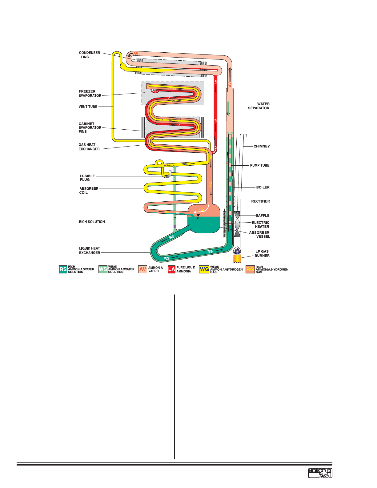
Gas Absorption System
Fig. 3 - Gas Absorption System
A rich solution (RS) leaves the absorber vessel and passes
through the liquid heat exchanger to the bottom of the pump
tube. Utilizing an AC cartridge heater or a LP gas burner, a
precise heat is applied to this area which in turn causes the
temperature of the solution to rise. This temperature increase
causes ammonia and some water vapor to be driven out of
the solution, forming vapor bubbles which push columns of
liquid up the pump tube.
As these columns of liquid exit the pump tube the liquid falls
downward through the rectifi er where the temperature is
increased causing additional ammonia vapor to be released.
The remaining liquid, now a weak ammonia-water solution
(WS), fl ows through the external shell of the liquid heat
exchanger where it transfers its residual heat to the rich
solution (RS) and enters the top of the absorber coil at a
reduced temperature. The ammonia-water vapor passes
through the water separator whose reduced temperature
causes any water vapor to condense and drop back down to
the boiler mixing with the existing weak solution (WS). The
ammonia vapor (AV) rises and enters the condenser where
it condenses (liquefi es) into pure liquid ammonia (LA). The
liquid ammonia, via gravity, drops into the tubular coil of the
freezer and cabinet evaporators and wets the internal surface
of the tubes.
The weak ammonia-hydrogen gas that was previously
released at the top of the absorber coil passes over the
wetted surfaces of the evaporator tubing causing the liquid
ammonia to evaporate into the hydrogen. The now rich
ammonia-hydrogen gas mixture (RG) draws heat from inside
the refrigerator. The weight of the hydrogen-ammonia gas
mixture (RG) is heavier than that of the weak gas (WG).
Consequently, it falls through the gas heat exchanger into the
top of the absorber vessel. From this point it enters the bottom
of the absorber coil.
The rich ammonia-hydrogen gas mixture (RG) travels up
through the absorber and makes contact with the weak
solution (WS) traveling down from the top of the absorber. As
the weak solution (WS) drops through the absorber it absorbs
the ammonia from the rich ammonia-hydrogen gas mixture
(RS). The relatively pure hydrogen (WG) exits the top of the
absorber coils to the evaporator and the rich solution falls to
the bottom of the absorber vessel where the cycle starts again.
8
www.norcold.com/cda
Refrigerator Service ManualN611v, N811v Models
Electronic Controls
A precise heat is applied to the boiler area of the cooling
unit causing a chemical reaction within the cooling unit that
ultimately results in the refrigerator cooling. The heat applied is
done so by means of:
• AC cartridge type heater positioned in heater wells
welded to the surface of the boiler
• LP Gas burner positioned below the boiler such
that the heat from the fl ame is directed across the
surface of the boiler
These heat sources are turned on/off via a factory preset
Auto mode. The unit will attempt to operate the heat source
requirements in the following order of priority:
• 1st Priority Choice - Auto AC Mode
While in the Auto AC Mode, the AC cartridge heater
is operated to provide heat to the boiler area of the
cooling unit.
• 2nd Priority Choice - LP Gas Mode
While in the Auto LP Gas Mode, the LP gas burner
is operated to provide heat to the boiler area of the
cooling unit.
Theory of Operation Auto Modes
AC voltage is applied to the power board via the AC power
cord at terminals L1 (Hot) and L2 (Neutral). This AC voltage
will pass through the AGC Series, 8A, Fast Acting, Glass Tube
Fuse (F2) where it is then measured. This measurement is
communicated to the optical display board which determines if
the applied voltage is below or above 85VAC. If the voltage is
above 85VAC the determination is that AC voltage is available
and the optical display board will request the power board to
operate via the Auto AC Mode. If the voltage is below 85VAC
the determination is that AC voltage is NOT available and the
optical display board will automatically default to the Auto LP
Gas Mode and request the power board to operate via the
Auto LP Gas Mode (see below). If the control is not able to
establish a fl ame while operating in the Auto LP Gas Mode the
optical display board will:
Automatically default back to the Auto AC mode and wait for
AC voltage to return, displaying the following fault code
• Solid RED power indicator light
A thermistor is mounted on the fi n assembly located inside the
fresh food compartment. The thermistor acts as a temperature
sensor, reporting the temperature sensed to the optical
display. The optical display then relays this information to
the power board that then turns on/off the appropriate heat
source accordingly. The optical display board, power board,
thermistor, and other components within the refrigerator are
interconnected via a wire harness.
Auto AC Mode
When operating in the Auto AC mode the power board
measures the thermistor value and communicates it to the
optical display board. The thermistor, a temperature device
whose internal resistance goes down as the temperature goes
up, is connected to the power board via terminals P2-1 and
P2-6. The optical display board compares the actual thermistor
value to preset cut-in and cut-out temperature values. Should
the thermistor value fall below the cut-in value it will request
the power board to turn ON the AC heater relay (K2). Should
the thermistor value go above the cut-out value it will request
the power board to turn OFF the AC heater relay.
Anytime relay K2 is turned ON, AC voltage is applied to
the AC heater via the now closed K2 contacts. Anytime AC
voltage is applied to the AC heater, AC current is produced.
This AC current is measured by the power board and its
value communicated to the optical display board. The optical
display board determines if the AC current is within specifi ed
limitations. If below the minimum specifi ed limit, the optical
display board will automatically default to the Auto LP Gas
Mode and request the power board to operate via the Auto
LP Gas Mode. AC related faults (Voltage or Current) are not
displayed while operating in the Auto Mode of operation.
www.norcold.com/cda
N611v, N811v ModelsRefrigerator Service Manual
9
 Loading...