

Page 1
Service Manual
Gas/Electric Refrigerators
MODELS
N61X/N81X
N62X/N82X
N64X/N84X
N64XIM/N84XIM
N64X.3/N84X.3
WARNING
!
DO NOT install this refrigerator in below deck marine applications. Do not
install this refrigerator in fixed indoor cabin or other dwelling applications. This
refrigerator must use only NORCOLD designed and approved outside air intake and exhaust ventilation for correct and safe operation. Any other ventilation could cause lethal combustion exhaust fumes and or/explosive propane
gas fumes to be in the living area and/or below deck.
© 2003 THETFORD/NORCOLD. All rights reserved.
Publication No. 619394E (01-28-04)
Page 2
TABLE OF CONTENTS
Introduction------------------------------------------------------ 1
About this Manual ................................................................. 1
Model Identification............................................................... 1
Information Label .................................................................. 1
Cooling Unit Serial Number .................................................. 1
Certification and Code Requirements ..................................1
About Installation .................................................................. 1
Replacement Parts ............................................................... 1
Technical Assistance.............................................................1
Safety Awareness --------------------------------------------- 3
Safety Notice......................................................................... 3
Attention Statements............................................................. 3
Safety Statements................................................................. 3
Specifications--------------------------------------------------- 4
N61X/N81X Models .............................................................. 4
N62X/N82X Models .............................................................. 5
N64X/N64X.3/N84X/N84X.3 Models .................................... 6
Troubleshooting – Quick Reference Guide ----------- 7
N61X/N81X Displayed Fault Codes ---------------------- 8
N62X/N82X Displayed Fault Codes ---------------------- 9
N64X/N84X Displayed Fault Codes --------------------- 10
Troubleshooting Flowcharts ------------------------------11
Blank Display – Refrigerator does not turn on ................... 11
F/no FL Fault Code – Burner failed to ignite or reignite..... 12
S/Sr Fault Code – Flame sense circuit failure.................... 13
dc LO Fault Code – Low DC voltage .................................. 13
dc HI Fault Code – DC voltage high................................... 14
dc rE Fault Code – DC relay stuck closed .........................14
dc HE Fault Code – DC heater failed open........................ 15
A/no AC Fault Code – No AC power available ................... 16
r/AC rE Fault Code – AC relay stuck closed ...................... 16
AC HI Fault Code – AC voltage high.................................. 17
AC LO Fault Code – AC voltage low .................................. 17
H/AC HE Fault Code – AC heater failed open ................... 18
Food Compartment Lamp Switch ....................................... 19
Lamp Switch Operation.....................................................19
d/dr Fault Code – Door open for more than 2 minutes ...... 19
Lamp Switch Testing Procedure ....................................... 19
Thermistor Failure Fault – Controls in backup operating
system mode....................................................................... 20
Backup Operating System (BOS)....................................... 20
N61X/N81X Backup Operation. ........................................ 20
N62X/N82XN64X/N84X Backup Operation...................... 20
Power Board Resetting Procedure ..................................... 21
n/no co Fault Code – No cooling detected by the controls 21
Ventilation -------------------------------------------------------22
Roof Exhaust Venting ......................................................... 22
Air Intake Vent..................................................................... 22
Roof Exhaust Vent .............................................................. 22
Baffles ................................................................................. 23
Vertical Angled Baffles ...................................................... 23
Double Sidewall Venting..................................................... 24
Air Intake Vent................................................................... 24
Sidewall Exhaust Vent ...................................................... 24
LP Gas System ------------------------------------------------27
Pressure Requirements ...................................................... 27
Testing for LP Gas Leaks ...................................................27
Components........................................................................ 28
Solenoid Gas Valves ......................................................... 28
New Style Solenoid Gas Valve .........................................28
Old Style Solenoid Gas Valve ........................................... 28
Solenoid Gas Valve Connections .....................................28
Orifice ................................................................................29
Burner................................................................................29
Burner Tube ...................................................................... 29
Flue ................................................................................... 30
Heat Deflector ................................................................... 30
Flue Baffle ......................................................................... 30
Flame Appearance..............................................................30
Burner Cleaning Procedure ................................................ 31
Electrical Requirements and Components-----------33
DC Voltage Requirements and Polarity..............................33
Power Board DC Fuse ...................................................... 33
DC Power Wiring Requirements......................................... 33
2-Way Models ................................................................... 33
3-Way Models ................................................................... 33
AC/DC Converter as Power Source ................................... 33
DC Heater–3-Way Refrigerators Only .............................. 33
DC Heater Circuit Fuse..................................................... 33
Lamp Assembly................................................................. 34
Divider Heater ................................................................... 34
AC Heater .........................................................................34
AC Power Requirements .................................................... 34
AC Heater Fuse ................................................................34
AC Power Cord ................................................................. 35
Power Cord for Ice Maker Units........................................35
12 Vdc Ventilation Fan........................................................35
Cooling Unit ----------------------------------------------------37
Description .......................................................................... 37
Heat Absorption ................................................................ 37
Leveled Operation............................................................. 37
Gradual Decrease in Cooling Efficiency............................. 37
Cooling System Monitoring.................................................37
First "No Cooling" Fault Occurrence.................................37
Two Recorded "No Cooling" Fault Occurrences .............. 37
Troubleshooting Cooling Faults..........................................38
Poor or No Cooling on AC Mode ...................................... 38
Poor or No Cooling on LP Gas Mode ............................... 38
Poor or No Cooling on DC Mode – 3-Way Models........... 38
Refrigerant Leakage ........................................................... 38
Disposal of Cooling Unit ..................................................... 38
Cooling System Diagnostic Flowchart................................ 39
Replacing the Cooling Unit ................................................. 41
Removing the Refrigerator from the Enclosure................ 41
Removal of Cooling Unit ................................................... 42
Installation of Replacement Cooling Unit ........................42
Reinstallation of Refrigerator into Enclosure .................... 44
Electronic Components ------------------------------------45
Power Board ....................................................................... 45
Removal–Power Board ..................................................... 45
Installation–Power Board ..................................................46
Optical Control Assembly ................................................... 46
N61X/N81X Wiring Schematic............................................47
N61X/N81X Wiring Pictorial................................................47
N62X/N82X/N64X/N84X/N64X.3/N84X.3 Wiring Pictorial –
Units with serial number 851759 and higher..................... 48
N62X/N82X/N64X/N84X/N64X.3/N84X.3 Wiring Schematic –
Units with serial number 851759 and higher..................... 48
N62X/N82X/N64X/N84X/N64X.3/N84X.3 Wiring Pictorial –
Units with serial number lower than 851759 ...................... 49
N62X/N82X/N64X/N84X/N64X.3/N84X.3 Wiring Schematic –
Units with serial number lower than 851759 ...................... 50
Controls----------------------------------------------------------51
N61X/N81X Optical Control Assembly ............................... 51
Front Box........................................................................... 51
Removal and Installation of Optical Control Assembly..... 51
Modes of Operation ............................................................ 52
Refrigerator Service Manual
www.norcold.com/cda
N6XX/N8XX Models
i
Page 3

AUTO Mode ...................................................................... 52
No AC Power ..................................................................... 52
AC Power Restored ..........................................................52
No AC and No Flame........................................................ 52
GAS Mode......................................................................... 52
No Flame........................................................................... 52
Backup Operating System .................................................. 52
“Gas Lock-Out” ................................................................... 52
N62X/N82X Optical Control Assembly ............................... 53
Front Box........................................................................... 53
Removal and Installation of Optical Control Assembly..... 53
Modes of Operation ............................................................ 54
AUTO Mode ...................................................................... 54
AUTO AC Operation ......................................................... 54
AUTO LP Gas Operation .................................................. 54
Shift from AUTO LP GAS to AUTO AC ............................. 54
No AC Power and No Flame.............................................54
Troubleshooting a "F"/"no" "FL" and "A"/"no" "AC" Faults 54
AC-Manual Mode .............................................................. 54
LP Gas–Manual Mode ...................................................... 54
No AC Power or Loss of AC Power ..................................55
Troubleshooting a "A"/"no" "AC" Fault..............................55
AC Power Restored ..........................................................55
Flame Fails to Ignite or Flame Goes Out .........................55
Clearing "Gas Lock-Out"................................................... 55
Troubleshooting a "F"/"no" "FL" Fault...............................55
N64X/N84X Optical Control Assembly ............................... 56
Front Box........................................................................... 56
Removal and Installation of Optical Control Assembly..... 56
Modes of Operation ............................................................ 57
AUTO ................................................................................ 57
AUTO AC Operation ......................................................... 57
AUTO LP Operation.......................................................... 57
Shift from AUTO LP GAS to AUTO AC ............................. 57
No AC Power and No Flame............................................. 57
Shift from AUTO LP GAS to AUTO AC ............................. 57
Troubleshooting No Flame and No AC Faults.................. 57
AUTO DC Operation – 3-Way Units Only......................... 58
AC-Manual Mode ................................................................ 58
No AC Power or Loss of AC Power ..................................58
AC Power Restored ..........................................................58
Troubleshooting "no" "AC" Fault....................................... 58
LP-Manual Mode................................................................. 59
Flame Fails to Ignite or Flame Goes Out .........................59
DC-Manual Mode................................................................ 59
No DC Power to DC Heater Circuit .................................. 59
Diagnostic Mode — Models N62X/N82X --------------60
Diagnostic Mode ................................................................. 60
Accessing the Diagnostic Mode ....................................... 60
Changing Screens ............................................................60
Exiting the Diagnostic Mode ............................................. 60
Screens and Diagnostic Segments Information ............... 61
Diagnostic Mode — Models N64X/N84X --------------63
Diagnostic Mode ................................................................. 63
Accessing the Diagnostic Mode ....................................... 63
Changing Screens ............................................................63
Exiting the Diagnostic Mode ............................................. 63
Screens and Diagnostic Segments Information ................. 64
Ice Maker --------------------------------------------------------66
Wire Harness ...................................................................... 66
Fill Tube .............................................................................. 66
Water Valve......................................................................... 66
Specifications...................................................................... 66
Replacing the Ice maker..................................................... 67
Ice Maker Troubleshooting Chart ....................................... 67
Cycle Test ........................................................................... 68
Water Fill Adjustment .......................................................... 69
Low Ice Yield....................................................................... 69
Water Valve Operation Test ................................................ 69
Water Valve Solenoid Resistance ...................................... 69
Mold Heater Resistance Check .......................................... 70
Checking Voltage at Motor Terminals................................. 70
Winterizing the Ice Maker Water ........................................ 70
N64X IM/N84XIM – Wiring Pictorial for Ice Maker Wired to
Refrigerator AC Cord ..........................................................70
N64X IM/N84XIM – Wiring Schematic for Ice Maker Wired to
Refrigerator AC Cord ..........................................................70
N64X IM/N84XIM – Wiring Schematic for Ice Maker Wired to
White AC Power Cord......................................................... 72
N64X IM/N84XIM – Wiring Pictorial for Ice Maker Wired to
White AC Power Cord......................................................... 72
ii Refrigerator Service Manual www.norcold.com/cda N6XX/N8XX Models
Page 4
INTRODUCTION
About this Manual
This service manual provides maintenance, diagnostic,
and repair information for NORCOLD® models N6XX
and N8XX (N6XX/N8XX) gas absorption refrigerators. It
is a reference tool designed for technicians who are
knowledgeable in the theory and operation of gas/
electric absorption refrigerators, liquefied petroleum
(LP) gas–propane–systems, and AC/DC electrical
systems as installed in a variety of recreational
vehicles (RV).
All information, illustrations, and specifications
contained in this publication are based on the latest
product information available at the time of publication.
NORCOLD® reserves the right to make changes at any
time without notice.
Model Identification
Models N61X, N81X, N62X, N82X, N64X, and N84X are
2-way refrigerators that operate on AC power or LP
gas.
Models N64X.3 and N84X.3 are 3-way refrigerators,
that operate on AC power , LP gas, or DC power .
Letter(s) appended to the model number identify
factory installed accessories. For example, an N821F
is a 2-way refrigerator equipped with a factory installed
12 Vdc cooling unit ventilation fan; an N641IM is a 2way refrigerator equipped with an ice maker.
Certification and Code Requirements
NORCOLD® N6XX/N8XX gas/electric absorption
refrigerators are certified under the latest edition of
ANSI Z21.19B standards for installation in mobile
homes or recreational vehicles, and with the Canadian
Standards Association CAN/CGA-1.4-M94.
Electrical components are compliant.
About Installation
Refrigerator installation must conform with the N6XX/
N8XX Installation Manual for the NORCOLD® limited
warranty to be in effect. Installation must also comply
with applicable local codes and standards set by the
cognizant certification agency .
Replacement Parts
Use only authorized NORCOLD® replacement parts.
Generic parts do not meet NORCOLD® specifications
for safety , reliability , and performance. The use of
unauthorized aftermarket or generic replacement parts
voids the refrigerator's limited warranty coverage.
T echnical Assistance
If unable to resolve technical issues using the
information provided in this manual, technical support
is available through NORCOLD® Customer Service
Center:
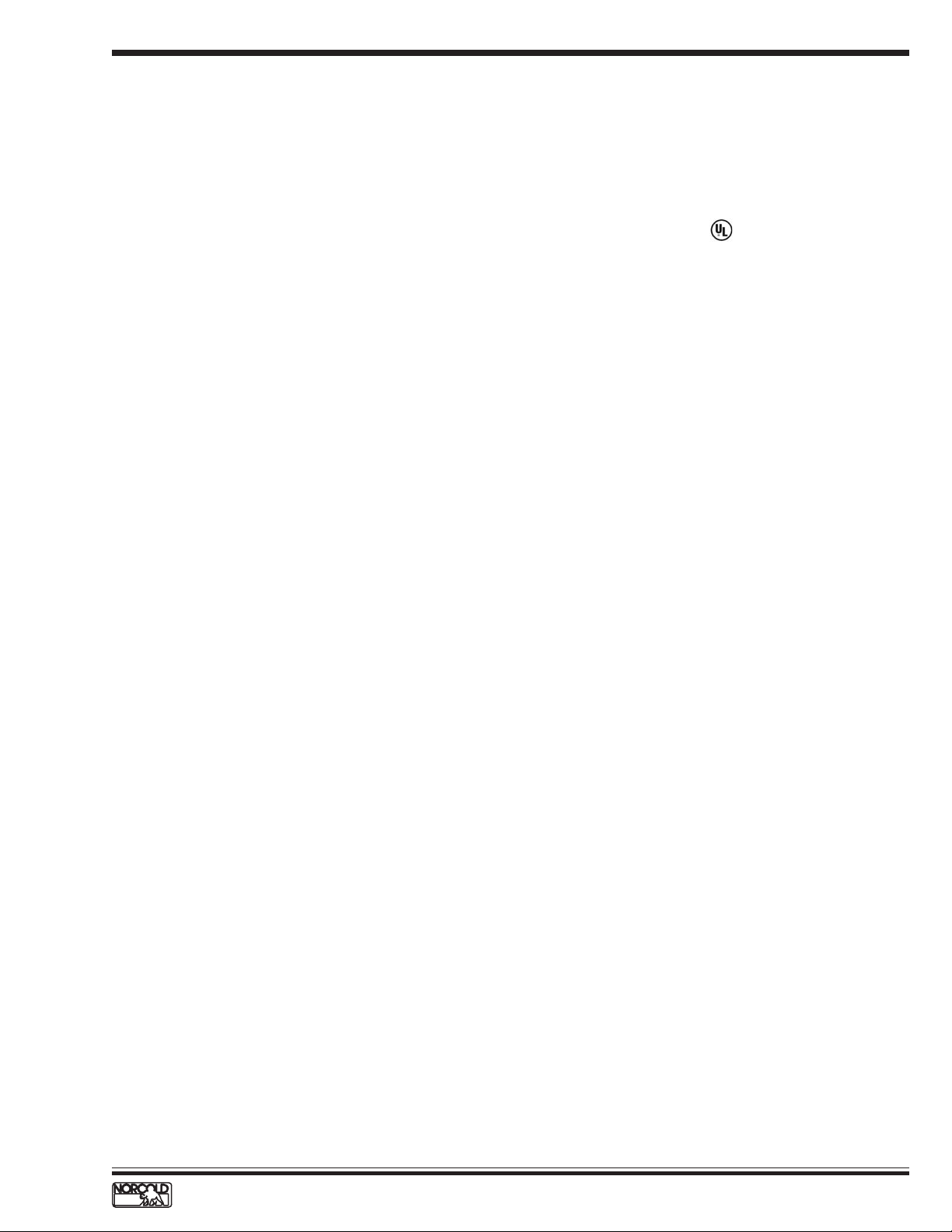
Information Label
The information label is located in the upper right
corner of the fresh food compartment just below the
divider. See Figure 1, p age 2. The label provides the
following information:
n Serial number.
n Model number.
n LP gas (propane) pressure.
n Btu/h.
n AC voltage and amperage.
n DC voltage and amperage.
n Design certification.
n Vent kit requirement.
Cooling Unit Serial Number
The cooling unit serial number appears on the cooling
unit bar code label. The label is affixed to the surface
of the cooling unit leveling chamber. See Figure 2,
page 2.
' Telephone:.................................... 1-800-444-7210.
7 Fax:.............................................. 1-937-497-3183.
; World Wide Web: ......................www.norcold.com.
The following information is required to process
technical support requests:
n Model number.
n Serial number.
n Make, model, and year of recreational vehicle.
www.norcold.com/cda 1N6XX/N8XX ModelsRefrigerator Service Manual
Page 5
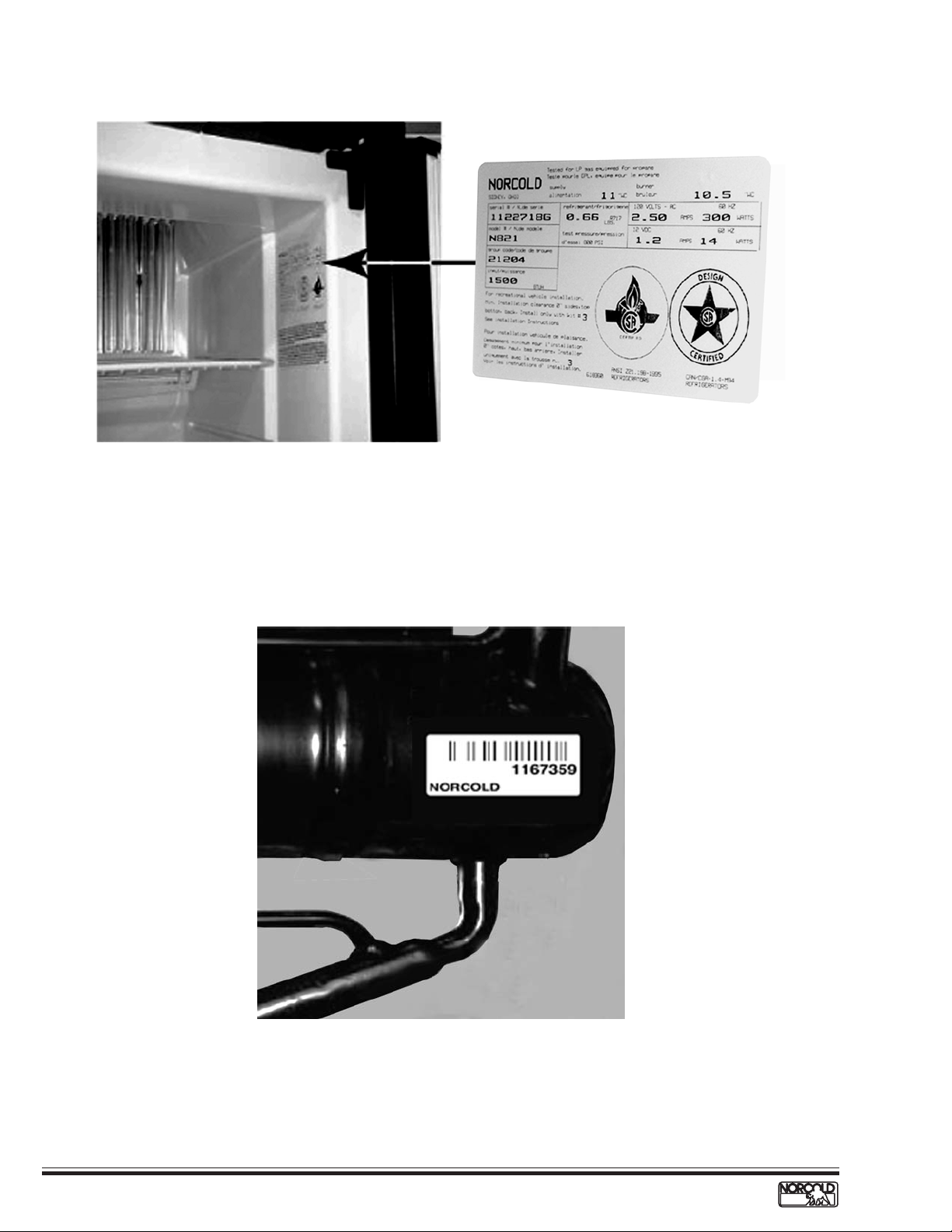
Figure 1. Refrigerator Information Label Location.
Figure 2. Cooling Unit Bar Code Label Location.
2
www.norcold.com/cda
Refrigerator Service ManualN6XX/N8XX Models
Page 6
Safety Notice
It is not possible to anticipate all of the conceivable
ways or conditions under which the refrigerator may be
serviced or to provide cautions as to all of the possible
hazards that may result. Standard and accepted safety
precautions and equipment should be used when
working on electrical circuits and handling toxic or
flammable materials. Safety goggles and other
required protection should be used during any process
that can cause material removal, such as when
removing a leaking cooling unit and cleaning
components.
Attention Statements
The safety alert symbol followed by the word
WARNING or CAUTION identifies potential safety
hazards or conditions.
Safety Statements
Do not modify, alter, or equip the refrigerator to the
use of any other fuel (natural gas, butane, etc.). N6XX/
N8XX refrigerators are designed and equipped for the
use of LP gas–propane gas–only.
Incorrect installation, adjustment, alteration, or
maintenance of the refrigerator can cause personal
injury, property damage, or both.
SAFETY AW ARENESS
The safety alert symbol with the appropriate heading
appear on all safety labels posted on the refrigerator
and safety awareness notices presented throughout
this manual.
!
WARNING:
The above heading identifies hazards or conditions,
which if ignored can cause serious injury , death, and/
or extensive property damage.
!
CAUTION:
The above heading identifies hazards, which if ignored
can cause injury and/or property damage.
Do not use leak test solutions that contain ammonia
or chlorine. Ammonia and chlorine degrade copper and
brass components.
The cooling unit is a sealed system under
pressure! Do not try to repair or recharge the cooling
unit. Do not bend, drop, weld, drill, puncture, saw, or
strike the cooling unit.
Do not smoke, light fires, or create sparks when
working on the propane gas system.
Do not use an open flame for leak testing any of the
propane gas system components. Propane gas is
highly flammable and explosive.
Always use two wrenches to tighten or loosen LP gas
connections. Damaged connections, piping, and
components create the potential for gas leaks.
All electrical connections and repairs to the
refrigerator must comply with all applicable codes.
Refer to the certification and code requirements
section of the N6XX/N8XX Installation Manual.
Do not work on live electrical circuits. Turn off AC
power and DC power sources before attempting to
remove, service, or repair any of the refrigerator's
electrical or electronic components.
Do not modify, bypass, or eliminate any of the
refrigerator's electrical components, electronic circuits,
or propane gas system components.
Do not wet or spray liquids on or near electrical
connections or electronic components. Most liquids,
including leak detection solutions, are electrically
conductive and pose the potential for an electric shock
hazard, short electrical components, damage
electronic circuits, and/or ignite a fire.
Handle a leaking cooling unit with extreme
caution! The cooling unit contains ammonia,
hydrogen, and sodium chromate. Ammonia can cause
severe skin and eye burns. Hydrogen is highly
flammable, can ignite and burns with an intense flame.
Certain chromium compounds, such as sodium
chromate, are carcinogenic.
Do not use extension cords. Do not remove the
grounding prong from the refrigerator AC power cord.
Do not use a two prong adapter to connect the
refrigerator to the AC outlet.
Do not over-fuse electrical circuits. Use specified
fuses and AWG wire sizes. The specification section
of this manual provides fuse size information. Refer to
the N6XX/8XX Installation Manual for the correct AWG
wire size specifications.
Prevent child entrapment! Before disposing of the
refrigerator, remove all doors and fasten all shelves
with retainers.
Some of the refrigerator's metal components have
sharp corners and edges. Wear hand protection, such
as cut resistant gloves, and exercise extreme care
when handling the refrigerator.
Make sure all hardware such as hinges and fasteners
(retaining screws, etc.), are properly fastened.
www.norcold.com/cda 3N6XX/N8XX ModelsRefrigerator Service Manual
Page 7
SPECIFICATIONS
N61X/N81X Models
Storage volume
N61X --------------------------------------------------------------------------------------------------------------------------------- 6.3 ft3.
N81X --------------------------------------------------------------------------------------------------------------------------------- 7.5 ft
Rough opening dimensions (H x W x D)
N61X ------------------------------------------------------------------------------------------------------ 52
N81X ----------------------------------------------------------------------------------------------------- 59
7
/8
in. x 23
7
/8
in. x 23
1/2
in. x 24 in.
1/2
in. x 24 in.
3
.
Decorative panels dimensions
3/16
Thickness--------------------------------------------------------------------------------------------------------------------------Freezer door (H x W, both models)---------------------------------------------------------------------14
17/32
in. x 21
19/32
in.
in.
Fresh food compartment (H x W)
N61X ------------------------------------------------------------------------------------------------------------- 31
N81X ------------------------------------------------------------------------------------------------------------- 38
5/8
in. x 21
5/8
in. x 21
19/32
19/32
in.
in.
Controls
Type ---------------------------------------------------------------------------------------------- Electronic with built-in diagnostics
Mode selector switch ------------------------------------------------------------------------------------------ 3-position slide type
T emperature switch--------------------------------------------------------------------------------------------- 5-position slide type
Temperature settings ---------------------------------------------------------------------------------------------- 1=cold, 5=coldest
T emperature sensor ----------------------------------------------------------------------------- Thermistor, fin mounted (10th fin)
Off-level operating limits
Side-to-side------------------------------------------------------------------------------------------------------- 3 degrees-maximum
Front-to-back----------------------------------------------------------------------------------------------------- 6 degrees-maximum
DC power
Controls operating voltage ----------------------------------------------------------------------------------------- 10.5 t o 15.4 Vdc
Fuse, control circuit (F1 in power board) -------------------------------------------- 5 A (tan color), automotive blade type
Fuse, fan (N6XXF/N8XX F models with an in-line fuse)--------------------- 1 A,
1
/4
in. x 1
1
in. AGC type fast acting
/4
DC amperage draws (at nominal 12 Vdc)
Automatic ignition----------------------------------------------------------------------------------------------------------------- 0.50 A
Divider heater ---------------------------------------------------------------------------------------------------------------------- 0.25 A
Fresh food compartment lamp ------------------------------------------------------------------------------------------------- 0.46 A
Gas valve--------------------------------------------------------------------------------------------------------------------------- 0.146 A
Fan (N6XX/FN8XXF models only)---------------------------------------------------------------------------------------------- 0.36 A
AC power
AC heater operating voltage ----------------------------------------------------------------------------------------- 108 to 132 Vac
Fuse, AC heater circuit (F3 in power board)---------------------------------- 5 A,
1
/4
in. x 1
1
in. AGC type fast acting
/4
AC heater rating ------------------------------------------------------------------ 300 W/2.5 A @ 120 Vac (resistance of 48Ω)
LP gas (propane)
Operating pressure ---------------------------------------------------------------------------------------------- 10.5 to 11.5 in. w.c.
Heat output--------------------------------------------------------------------------------------------------1500 Btu/h @ 11 in. w .c.
Orifice ---------------------------------------------------------------------------------------------------------------------------------- LP16
Gas ignition---------------------------------------------------------------------------------- Automatic with flame sensing circuit
Electrode tip-to-burner air gap---------------------------------------------------------------------------------------- 1/8 to 3/16 in.
4
www.norcold.com/cda
Refrigerator Service ManualN6XX/N8XX Models
Page 8
N62X/N82X Models
Storage volume
N62X --------------------------------------------------------------------------------------------------------------------------------- 6.3 ft3.
N82X --------------------------------------------------------------------------------------------------------------------------------- 7.5 ft
Rough opening dimensions (H x W x D)
N62X ------------------------------------------------------------------------------------------------------ 52
N82X ------------------------------------------------------------------------------------------------------ 59
7
/8 in. x 231/2 in. x 24 in.
7
/8
in. x 23
1
/2
in. x 24 in.
3
.
Decorative panels dimensions
3
Thickness--------------------------------------------------------------------------------------------------------------------------Freezer door (H x W, both models)---------------------------------------------------------------------14
17/32
in. x 21
/16
19/32
in.
in.
Fresh food compartment door
N62X --------------------------------------------------------------------------------------------------------------31
N82X --------------------------------------------------------------------------------------------------------------38
5
/8
in. x 21
5
/8 in. x 2119/32 in.
19
/32
in.
Controls
Type --------------------------------------------------------------------------------------- Electronic with built-in diagnostic mode
ON/OFF/MODE/TEMP SET switches ------------------------------------------------------------------------ Flush push-button
Temperature settings ---------------------------------------------------------------------------------------------- 1=cold, 9=coldest
T emperature sensor ----------------------------------------------------------------------------- Thermistor, fin mounted (10th fin)
Off-level operating limits
Side-to-side------------------------------------------------------------------------------------------------------- 3 degrees-maximum
Front-to-back----------------------------------------------------------------------------------------------------- 6 degrees-maximum
DC power
Controls operating voltage ----------------------------------------------------------------------------------------- 10.5 to 15.4 Vdc
Fuse, control circuit (F1 in power board) -------------------------------------------- 5 A (tan color), automotive blade type
Fuse, fan (N6XXF/N8XX F models with in-line fuse) ------------------------- 1 A,
1
/4
in. x 1
1
in. AGC type fast acting
/4
DC amperage draws (at nominal 12 Vdc)
Automatic ignition----------------------------------------------------------------------------------------------------------------- 0.50 A
Divider heater ---------------------------------------------------------------------------------------------------------------------- 0.25 A
Fresh food compartment lamp ------------------------------------------------------------------------------------------------- 0.46 A
Gas valve--------------------------------------------------------------------------------------------------------------------------- 0.146 A
Fan (N6XX/FN8XXF models only)---------------------------------------------------------------------------------------------- 0.36 A
AC power
AC heater operating voltage -----------------------------------------------------------------------------------------108 to 132 Vac
Fuse AC heater circuit (F3 in power board)----------------------------------- 5 A,
1
/4
in. x 1
1
in. AGC type fast acting
/4
AC heater rating
Refrigerators with serial number lower than 854647 -----------------300 W/2.7 A @ 110 V ac (resist ance of 41.25 Ω)
Refrigerators with serial number 854647 and higher --------- 300 W/2.5 A/48 Ω @ 120 Vac (resistance of 41.25 Ω)
LP gas (propane)
Operating pressure ---------------------------------------------------------------------------------------------- 10.5 to 11.5 in. w.c.
Heat input----------------------------------------------------------------------------------------------------1500 Btu/h @ 1 1 in. w .c.
Orifice, new style-------------------------------------------------------------------------------------------------------------------- LP16
Orifice, old style ----------------------------------------------------------------------------------------------------------0.155 jeweled
Gas ignition---------------------------------------------------------------------------------- Automatic with flame sensing circuit
Electrode tip-to-burner air gap --------------------------------------------------------------------------------------- 1/8 to 3/16 in.
www.norcold.com/cda 5N6XX/N8XX ModelsRefrigerator Service Manual
Page 9
N64X/N64X.3/N84X/N84X.3 Models
Storage volume
N64X/N64X.3 ----------------------------------------------------------------------------------------------------------------------- 6.3 ft
N84X/N84X.3 ----------------------------------------------------------------------------------------------------------------------- 7.5 ft3.
Rough opening dimensions (H x W x D)
N64X/N64X.3 --------------------------------------------------------------------------------------------52
N84X/N84X.3 --------------------------------------------------------------------------------------------59
7
/8 in. x 231/2 in. x 24 in.
7
in. x 23
/8
1
in. x 24 in.
/2
Decorative panels dimensions
Thickness---------------------------------------------------------------------------------------------------------------------------
17
Freezer door (H x W, both models) ---------------------------------------------------------------------14
in. x 21
/32
19
3
/16
in.
in.
/32
Fresh food compartment door
N64X/N64X.3 ----------------------------------------------------------------------------------------------------31
N84X/N84X.3 ----------------------------------------------------------------------------------------------------38
5
/8
5
/8
in. x 21
in. x 21
19
19
/32
/32
in.
in.
Controls
Type ------------------------------------------------------------------------------------ Electronic with built-in diagnostic function
ON/OFF/MODE/TEMP SET switches ---------------------------------------------------------------------- Raised push-button
Temperature settings ---------------------------------------------------------------------------------------------- 1=cold, 9=coldest
T emperature sensor ----------------------------------------------------------------------------- Thermistor, fin mounted (10th fin)
Off-level operating limits
Side-to-side------------------------------------------------------------------------------------------------------- 3 degrees-maximum
Front-to-back----------------------------------------------------------------------------------------------------- 6 degrees-maximum
DC power
Controls operating voltage ----------------------------------------------------------------------------------------- 10.5 to 15.4 Vdc
DC fuse (F1 in power board)------------------------------------------------------------ 5 A (tan color), automotive blade type
DC heater rating -----------------------------------------------------------------225 W/16 A @14 Vdc (resist ance of 0.87 Ω)
DC heater operating voltage (3-way models only) ------------------------------------------------------------------ 12 – 14 Vdc
Fuse, DC heater (F2, in power board) ------------------------------------------- 30 A (green color), automotive blade type
Fuse, fan (N6XXFw/N8XX F models with in-line fuse holder) -------------- 1 A,
1
/4
in. x 1
1
in. AGC type fast acting
/4
3
.
DC amp draws (at nominal 12 Vdc)
Automatic ignition----------------------------------------------------------------------------------------------------------------- 0.50 A
DC heater --------------------------------------------------------------------------------------- 13.79 A @ 12 Vdc/16 A @ 14 Vdc
Divider heater ---------------------------------------------------------------------------------------------------------------------- 0.25 A
Fresh food compartment lamp ------------------------------------------------------------------------------------------------- 0.46 A
Gas valve--------------------------------------------------------------------------------------------------------------------------- 0.146 A
Fan (N6XX/FN8XXF models only)---------------------------------------------------------------------------------------------- 0.36 A
AC power
AC heater operating voltage requirements ----------------------------------------------------------------------- 108 to 132 V ac
Fuse AC heater circuit (F3 in power board)------------------------------------ 5 A,
1
/4
in. x 1
1
in. AGC type fast acting
/4
AC heater rating
Refrigerators with serial number lower than 854647 -----------------300 W/2.7 A @ 110 V ac (resist ance of 41.25 Ω)
Refrigerators with serial number 854647 and higher -------------------- 300 W/2.5 A @ 120 V ac (resist ance of 48 Ω)
LP gas (propane)
Operating pressure ----------------------------------------------------------------------------------------------- 10.5 to 11.5 in. w.c
Heat input-----------------------------------------------------------------------------------------------------1500 Btu/h @ 11 in. w .c
Orifice, new style-------------------------------------------------------------------------------------------------------------------- LP16
Orifice, old style ----------------------------------------------------------------------------------------------------------0.155 jeweled
Gas ignition---------------------------------------------------------------------------------- Automatic with flame sensing circuit
Electrode tip-to-burner air gap --------------------------------------------------------------------------------------- 1/8 to 3/16 in.
6
www.norcold.com/cda
Refrigerator Service ManualN6XX/N8XX Models
Page 10
TROUBLESHOOTING – QUICK REFERENCE GUIDE
Problem Possible Cause Checks/Reference
The refrigerator does not turn ON.
The refrigerator does not cool on
AC power.
The refrigerator does not cool
efficiently on AC power.
3-Way Units Only
The refrigerator does not cool on
DC power.
3-Way Units Only
The refrigerator does not cool
efficiently on DC power.
No 12 Vdc power to refrigerator.
Faulty/loose 12 Vdc connections.
F1 fuse in power board open.
No AC power to refrigerator.
F3 fuse in the power board open.
AC heater failed open.
Ventilation obstructed.
AC voltage low.
F2 fuse in power board open.
DC heater failed open.
Ventilation obstructed.
DC voltage below 12 volts.
See page 11.
Check 12 Vdc connections.
Check fuse F1, (5 amp) in power board.
See page 16.
Check fuse F3, (5 amp) in power board.
See page 18.
Check enclosure for air flow obstructions.
See page 17.
Check fuse F2 (30 amp) in power board.
See page 15.
Check enclosure for obstructed air flow.
Check RV 12 Vdc power supply.
The refrigerator does not operate
on LP gas.
The refrigerator does not
cool efficiently on LP gas.
"no" "co" code.
No LP gas.
Incorrect electrode tip-to-burner gap.
Faulty spark/sense electrode assembly.
Flame sensing circuit failure.
Ventilation obstructed.
Incorrect LP gas pressure.
Dirty burner.
Missing flue baffle.
Heat deflector blocked.
Poor ventilation.
Off-level operation.
DIrty burner.
Low AC voltage.
Cooling fan inoperative.
Improper installation.
Incorrect orifice.
Check LP gas supply and valves.
See page 12.
See page 12.
See page 13.
Check enclosure for obstructed air flow.
See page 12.
See page 12.
See page 30.
See page 30.
Check enclosure for obstructed air flow.
See page 37.
See page 31.
See page 34.
See page 35.
See pages 22-26.
See page 29.
www.norcold.com/cda 7N6XX/N8XX ModelsRefrigerator Service Manual
Page 11
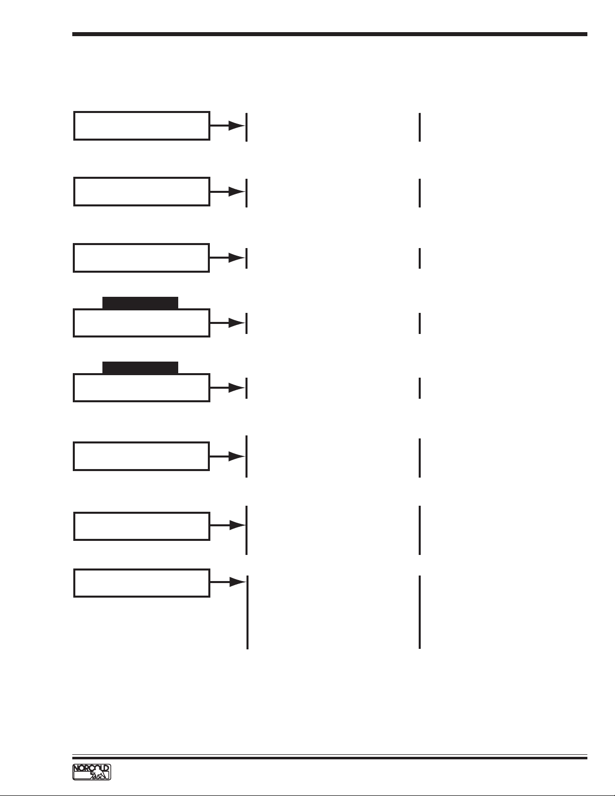
N61X/N81X DISPLA YED FAUL T CODES
Problem
ON LED off.
ON LED and GAS LED flashing at one second
intervals.
ON LED on.
GAS LED flashes at one second intervals.
ON LED flashes once every three seconds.
Probable Cause
Refrigerator turned off.
No 12 Vdc to refrigerator.
F1 fuse open.
In AUTO operation:
No AC power or LP gas available
GAS operation:
Burner failed to ignite or reignite.
"Gas lock-out."
Burner failed to ignite or reignite.
Back-up system operation.
Reference
See page 11.
See page 16.
See page 12.
See page 12.
See page 20.
ON LED flashes twice every three seconds.
ON LED flashes three times every three
seconds.
ON LED flashes four times every three seconds.
ON LED flashes five times every three seconds.
Mode switch failure. Refrigerator
operating in last selected mode.
AC heater failure.
Controls failure.
No cooling detected by the controls.
Replace optical
control assembly.
See page 18.
Replace
power board.
See pages
21 & 37.
8
www.norcold.com/cda
Refrigerator Service ManualN6XX/N8XX Models
Page 12
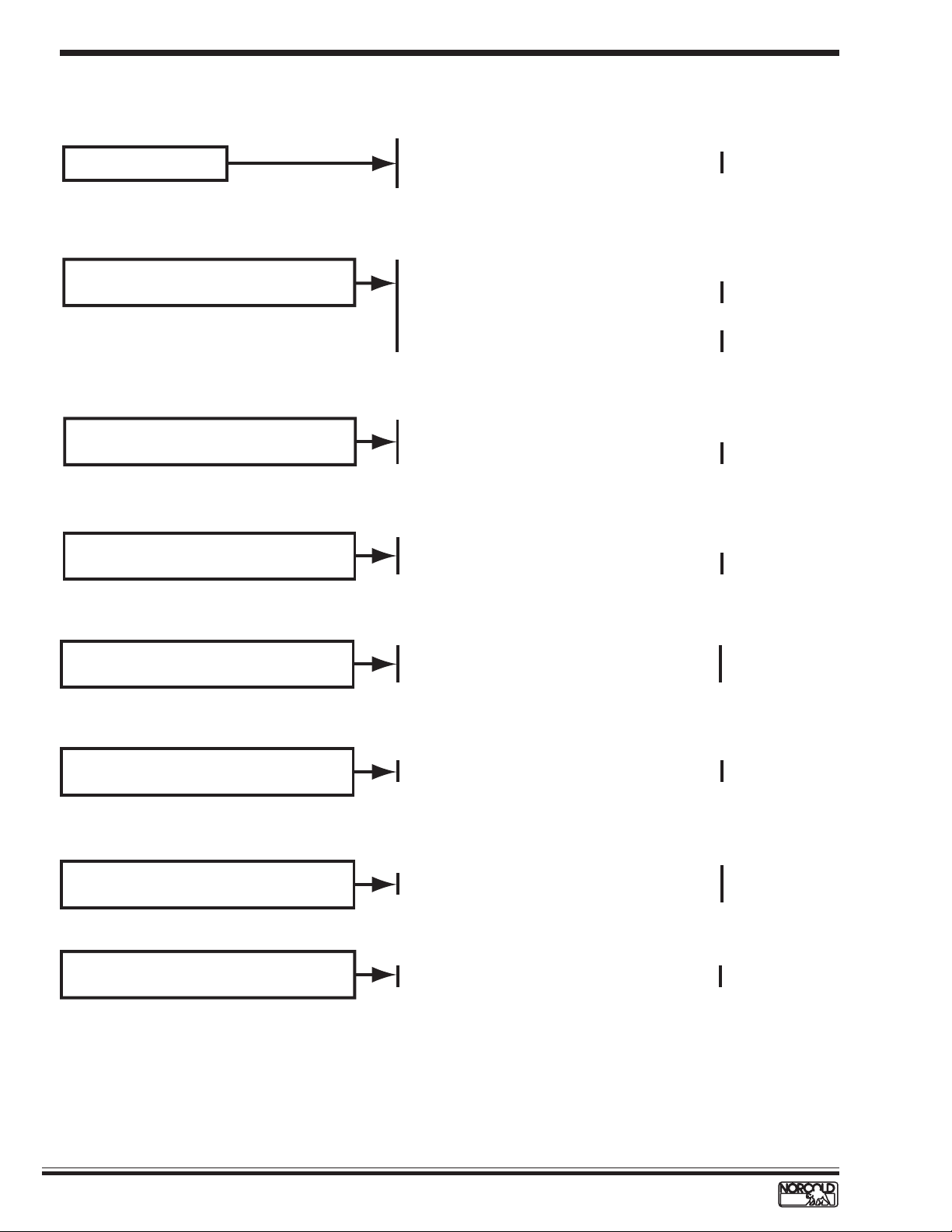
N62X/N82X DISPLA YED FAUL T CODES
Blank
Display
Screen
Probable Cause
Refrigerator turned off.
No 12 Vdc to refrigerator.
F1 fuse open.
Burner failed to ignite or reignite.
Flame sense circuit failure.
DC voltage low.
DC voltage high.
ReferenceCode
See page 11.
See page 12.
See page 13.
See page 13.
See page 14.
Flashing
Tem p
Setting
AC relay stuck closed.
No AC power available to refrigerator.
AC cord not plugged into power board.
F3 fuse open.
AC heater failed open.
Fresh food compartment door open more then 2 minutes.
Lamp reed relay switch faulty.
Back-up operating system.
No cooling detected by the controls.
See page 16.
See page 16.
See page 18.
See page 19.
See page 20.
See pages
21 & 37.
www.norcold.com/cda 9N6XX/N8XX ModelsRefrigerator Service Manual
Page 13
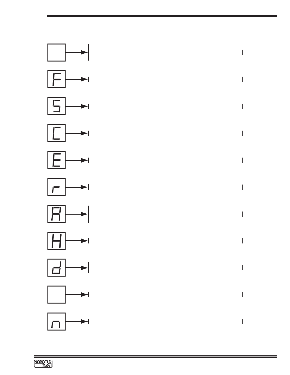
N64X/N84X DISPLA YED FAULT CODES
Code
Blank
Display
Screen
Probable Cause
Reference
Refrigerator turned off.
No 12 Vdc to refrigerator.
See page 11.
F1 fuse open.
a
t
i
n
n
r
g
e
t
l
A
y
D
a
l
i
s
p
Audible
Alarm
n
a
r
t
e
i
n
t
l
g
A
D
y
i
a
l
s
p
a
n
t
r
i
n
e
t
g
l
A
D
y
a
i
l
s
p
a
n
t
r
i
n
e
t
g
l
A
D
y
i
a
l
s
p
a
n
t
r
i
n
e
t
g
l
A
D
y
i
s
a
l
p
a
n
t
r
i
n
e
t
g
l
A
D
y
i
a
l
s
p
a
n
t
r
i
n
e
t
g
l
A
y
D
a
l
i
s
p
a
n
t
r
i
n
e
t
l
g
A
Audible
Alarm
Audible
Alarm
Audible
Alarm
Audible
Alarm
Audible
Alarm
The burner failed to ignite or reignite.
Flame sense circuit failure.
DC voltage low.
DC relay stuck closed, 3-way models only.
DC voltage high.
DC heater failure, 3-way models only.
No AC power available to refrigerator.
AC cord not plugged into power board.
F3 fuse open.
AC relay stuck closed.
See page 12.
See page 13.
See page 13.
See page 14.
See page 14.
See page 15.
See page 16.
See page 16.
10
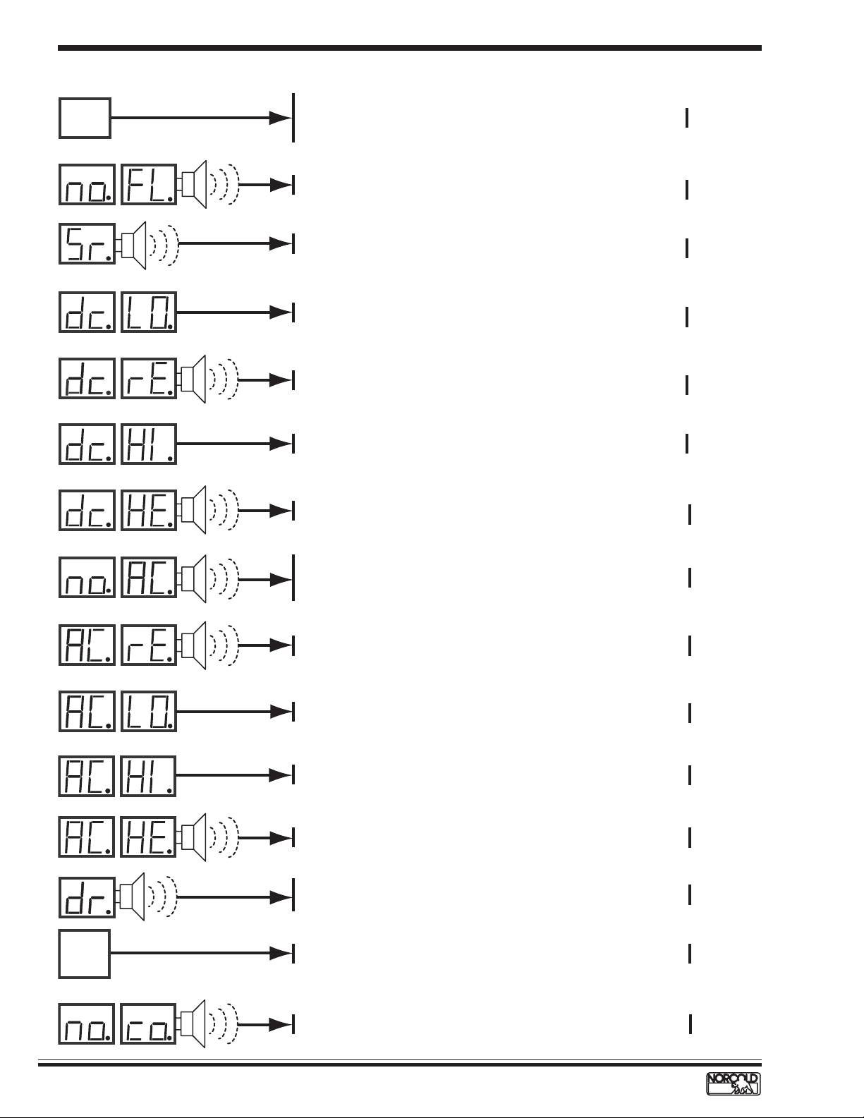
A
A
Flashing
Tem p
Setting
A
AC voltage low.
D
y
i
a
l
s
p
a
t
i
n
n
r
g
e
t
l
AC voltage high.
D
y
i
a
l
s
p
a
t
i
n
n
r
g
e
t
l
D
y
i
a
l
s
p
Audible
AC heater failed open.
Alarm
See page 17.
See page 17.
See page 18.
Audible
Fresh food compartment door open more than 2 minutes.
Lamp reed relay switch faulty.
See page 19.
Alarm
Back-up operating system.
a
t
n
i
r
n
e
g
t
l
Audible
No cooling detected by the controls.
D
y
i
a
l
s
p
Alarm
www.norcold.com/cda
Refrigerator Service ManualN6XX/N8XX Models
See page 20.
See pages
21 & 37.
Page 14
TROUBLESHOOTING FLOWCHARTS
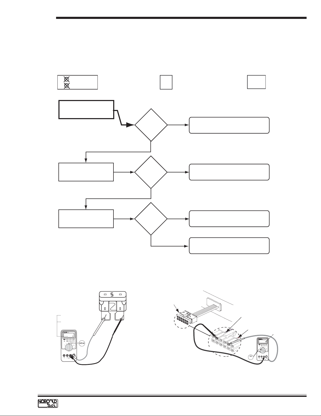
Blank Display – Refrigerator does not turn on
Before beginning this procedure make sure:
■
The RV DC power system is supplying 10.5 to 15.4 volts to the refrigerator.
■
No other RV appliances or lighting circuits are connected to the refrigerator DC circuit.
■
12 Vdc input to the power board is wired according to the N6XX/N8XX installation manual.
Models and fault indicator displayed.
ON
GAS
check if flashing
N61X/N81X
Measure voltage at power
board 12VDC and GND1
connections.
Check condition of F1 fuse
in power board. See Figure A.
Measure voltage at optical
control harness.
See Figure B.
AUTO
N62X/N82X
10.5
to
15.4 Vdc?
YES
F1 fuse okay?
YES
Voltage
present?
Blank
Display
Screen
LP GASAC
NO
NO
NO
Blank
Display
Screen
N64X/N84X
1. No DC power input from RV to unit.
2. Faulty wiring or connectors.
Replace fuse. Use a standard 5 amp
(tan color) automotive blade type fuse.
Replace power board.
Good= 00.0
Ω
Bad = OL
R
E
T
E
M
I
T
L
U
M
S
M
R
E
U
R
T
87
I
I
I
00.0
H
D
L
O
H
E
G
N
A
R
X
A
M
N
I
M
z
H
L
E
R
X
A
M
N
I
M
K
A
E
P
S
T
I
G
I
D
2
/
1
4
s
d
n
o
c
e
S
1
mV
mA
A
V
A
µ
V
F
F
O
V
M
O
C
A
µ
A
m
A
!
AX
M
A
0m
0
4
I
I
T
A
C
D
E
S
U
F
AX
M
V
0
0
0
1
X
A
M
A
0
1
D
E
S
U
F
!
Checking DC fuse continuity.
Figure A.
YES
Replace optical control board.
Wire harness optical
control display connector
White/violet wire
White/red wire
10.5 to 15.4 Vdc
TRUE RMS MULTI METER
87
III
V
H
MIN MAX RANGE HOLD
HzREL
PEAK MIN MAX
4 1/2 DIGITS
1 Seconds
mV
mA
V
A
µA
V
OFF
V
COM
A
mA µA
!
400mA MAX
CAT II
FUSED
1000V MAX
10A MAX
V
!
FUSED
Optical control display wire harness connection voltage measuring points.
Figure B.
www.norcold.com/cda 11N6XX/N8XX ModelsRefrigerator Service Manual
Page 15
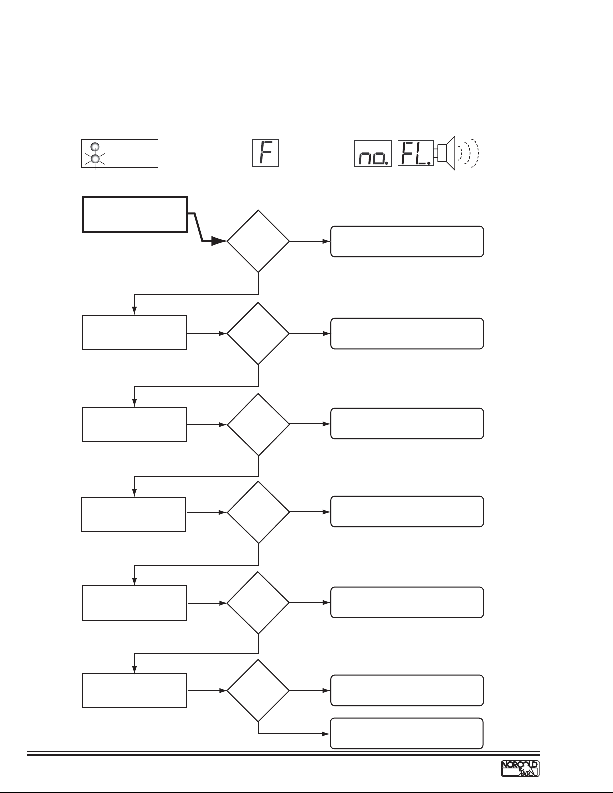
F/no FL Fault Code – Burner failed to ignite or reignite
Before beginning this procedure make sure:
■
RV LP gas tank valve is open.
■
Refrigerator solenoid gas valve manual shutoff is open.
■
LP gas pressure at the solenoid gas valve pressure tap is 10.5.
Models and fault indicator displayed.
ON
GAS
N61X/N81X
Check burner.
GAS LED
flashing
constantly
AUTO
N62X/N82X
LP GASAC
a
n
t
r
e
t
l
A
D
i
a
s
l
p
N64X/N84X
i
n
g
y
Audible
Alarm
Check that electrode tip-toburner air gap is correct.
Check spark/sense electrode
assembly for continuity.
Check gas valve solenoid
resistance.
.
Burner
clean?
YES
Air gap
1/8 to 3/16
inch?
YES
Continuity?
YES
79 to 85 Ω?
NO
NO
NO
NO
Clean and service burner.
See page 30.
Set electrode-to-burner air gap
1/8 to 3/16 inch.
Replace spark/sense electrode
assembly.
Replace gas valve.
12
Check gas valve solenoid
wires for continuity.
Check voltage across power
board terminals GV and
GV GND.
YES
Continuity?
NO
YES
Voltage?
NO
YES
www.norcold.com/cda
Replace gas valve wires.
Replace power board.
Faulty or obstructed gas valve.
Replace gas valve.
Refrigerator Service ManualN6XX/N8XX Models
Page 16
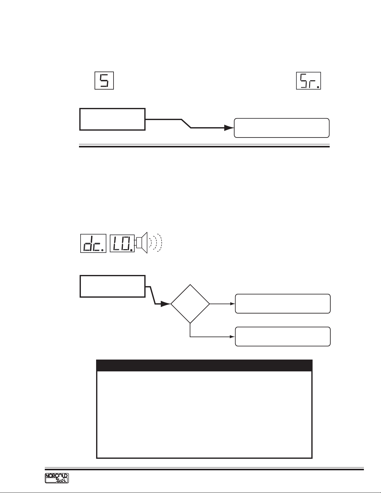
S/Sr Fault Code – Flame sense circuit failure
Models and fault indicator displayed.
LP GASAC
AUTO
N62X/N82X N64X/N84X
Flame sense circuit failure.
Replace power board.
See page 44.
dc LO Fault Code – Low DC voltage
Before beginning this procedure:
■
Make sure RV DC voltage to refrigerator is 10.5 to 15.4 volts.
■
Determine if the DC LO fault code displays when the converter is the source of DC power.
■
Make sure no other appliance or lighting circuit is connected to the refrigerator DC circuit.
Models and fault indicator displayed.
a
n
t
r
i
e
t
l
A
D
i
N64X/N84X
Check for DC voltage input
to power board terminals
12VDC and GND1.
n
g
y
a
s
l
p
Audible
Alarm
Voltage
lower than
10.5 Vdc?
YES
Check RV 12 Vdc power supply to
refrigerator.
NO
See NOTE below to determine
and correct low dc LO fault.
NOTE
Electronic controls operate on 12 Vdc. When an AC/DC converter is used to
supply DC power, the refrigerator circuit must be connected to the appliance
output terminals of the converter (filtered side).
If the refrigerator circuit is connected to the unfiltered side, the AC ripple
generated by the converter may cause a dc LO fault code to display .
T o troubleshoot a dc LO fault, connect a charged 12 volt automotive battery
to the power board. If the dc LO code clears, the fault was caused by unfiltered
DC power.
If the dc LO code does not clear, replace the power board.
www.norcold.com/cda 13N6XX/N8XX ModelsRefrigerator Service Manual
Page 17
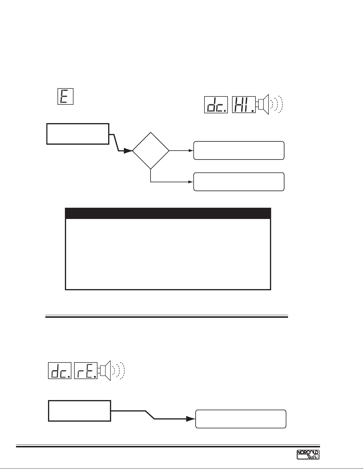
dc HI Fault Code – DC voltage high
Before beginning this procedure:
■
Make sure RV DC voltage to refrigerator is 10.5 to 15.4 volts.
■
Determine if the DC HI fault code displays when the converter is the source of DC power.
Models and fault indicator displayed.
a
n
t
r
i
n
g
AUTO
e
LP GASAC
A
t
l
Audib
le
N62X/N82X
Check for DC voltage input
to power board terminals
12VDC and GND1.
Electronic controls operate on 12 Vdc. When an AC/DC converter is used to
supply DC power, the refrigerator circuit must be connected to the appliance
output terminals of the converter (filtered side).
If the refrigerator circuit is connected to the unfiltered side, the AC ripple
generated by the converter may cause a dc HI fault code to display .
T o troubleshoot a dc HI fault, connect a charged 12 volt automotive battery to
the power board. If the dc HI code clears, the fault was caused by unfiltered
DC power. If the dc HI code does not clear , replace the power board.
Voltage
higher than
15.4 Vdc?
NOTE
YES
NO
D
y
i
a
s
l
p
N64X/N84X
Check RV DC power distribution to
refrigerator.
See NOTE below to determine
and correct low dc HI fault.
Alarm
14
dc rE Fault Code – DC relay stuck closed
Models and fault indicator displayed
a
n
t
r
i
n
e
t
g
l
A
D
y
i
a
l
s
p
N64X/N84X
DC relay stuck closed.
Audib
Alarm
le
www.norcold.com/cda
Replace power board.
See page 44.
Refrigerator Service ManualN6XX/N8XX Models
Page 18
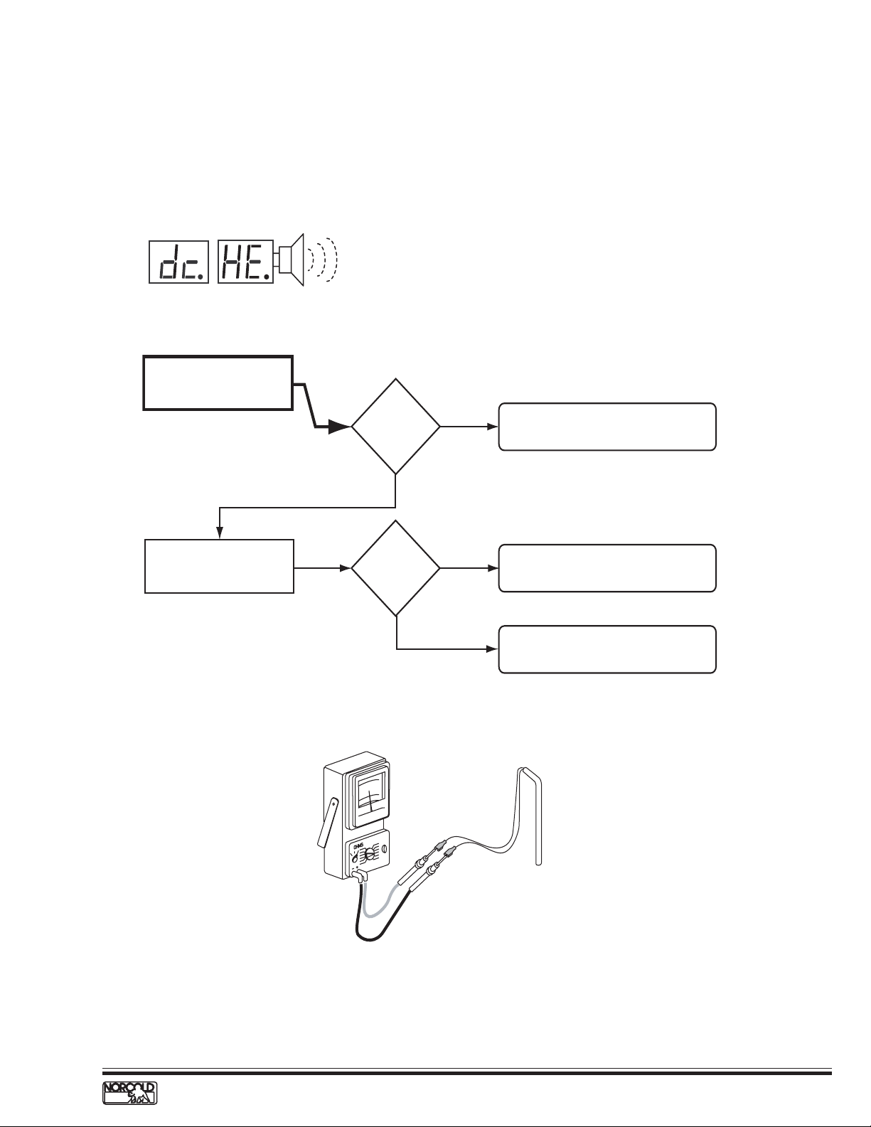
dc HE Fault Code – DC heater failed open
Before beginning this procedure make sure:
■
The RV DC electrical system is maintaining 10.5 to 15.4 Vdc to the refrigerator.
■
No other appliance or lighting circuit is connected to the refrigerator DC circuit.
Model and fault indicator displayed.
a
n
t
r
i
A
e
t
l
n
g
Audible
D
N64X.3/N84X.3
Check condition of F2 fuse
in power board.
Check DC heater resistance.
See Figure.
y
i
a
s
l
p
Alarm
F2 fuse
okay?
YES
Resistance
0.81 to 0.91
YES
NO
NO
Ω
?
Replace fuse. Use a standard 30 amp
(green color) automotive blade type fuse.
Replace DC heater.
Replace power board.
DC heater resistance 0.81 to 0.91
www.norcold.com/cda 15N6XX/N8XX ModelsRefrigerator Service Manual
Ω.Ω.
Ω.
Ω.Ω.
Page 19
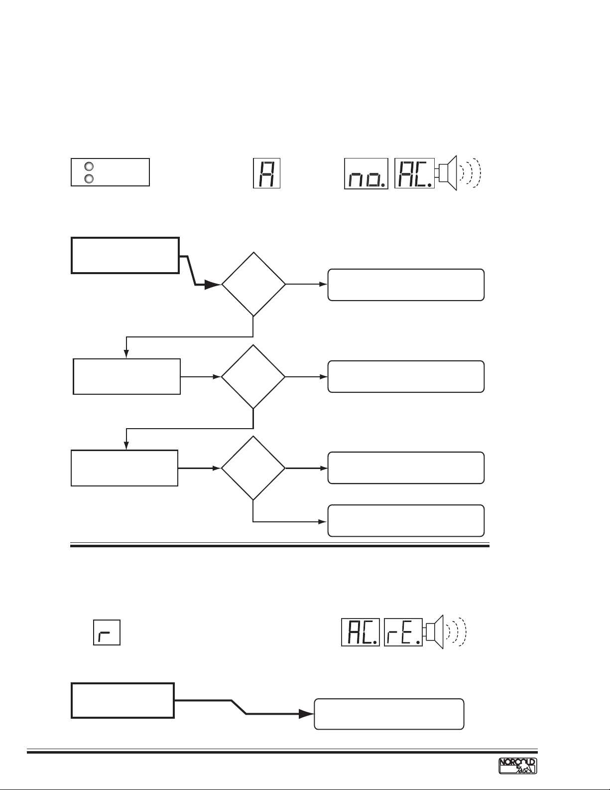
A/no AC Fault Code – No AC power available
Before beginning this procedure make sure:
■
No other problem exist with the RV AC power supply.
■
No other appliances or lighting circuits are connected to the refrigerator AC circuit.
■
Extension cords are not being used to supply AC power to the refrigerator.
Models and fault indicator displayed.
ON
GAS
check if flashing
Does not operate on AC when set to AUTO.
N61X/N81X
Measure voltage at power
board AC cord connection.
Check condition of F3 fuse
in power board.
AUTO
N62X/N82X
108
to
132 Vac?
YES
F3 fuse okay?
YES
a
n
t
r
i
A
e
t
l
n
g
Audib
e
l
LP GASAC
Alarm
NO
NO
D
y
i
a
s
l
p
N64X/N84X
1. Check AC power input from RV to unit.
2. Check for faulty AC power cord.
Replace fuse. Use a 5 amp, 1/4" x 11/4"
AGC type fuse.
Check that fuse holder clips
are making full contact with
fuse.
Clips okay?
YES
r/AC rE Fault Code – AC relay stuck closed
Models and fault indicator displayed.
LP GASAC
AUTO
N62X/N82X
Flame sense circuit failure.
NO
Adjust clips to ensure fuse contacts are
firm in clips and making full contact.
Replace power board.
a
n
t
r
i
n
e
t
g
l
A
D
y
i
a
l
s
p
Audib
Alarm
N64X/N84X
Replace power board.
See page 44.
le
16
www.norcold.com/cda
Refrigerator Service ManualN6XX/N8XX Models
Page 20
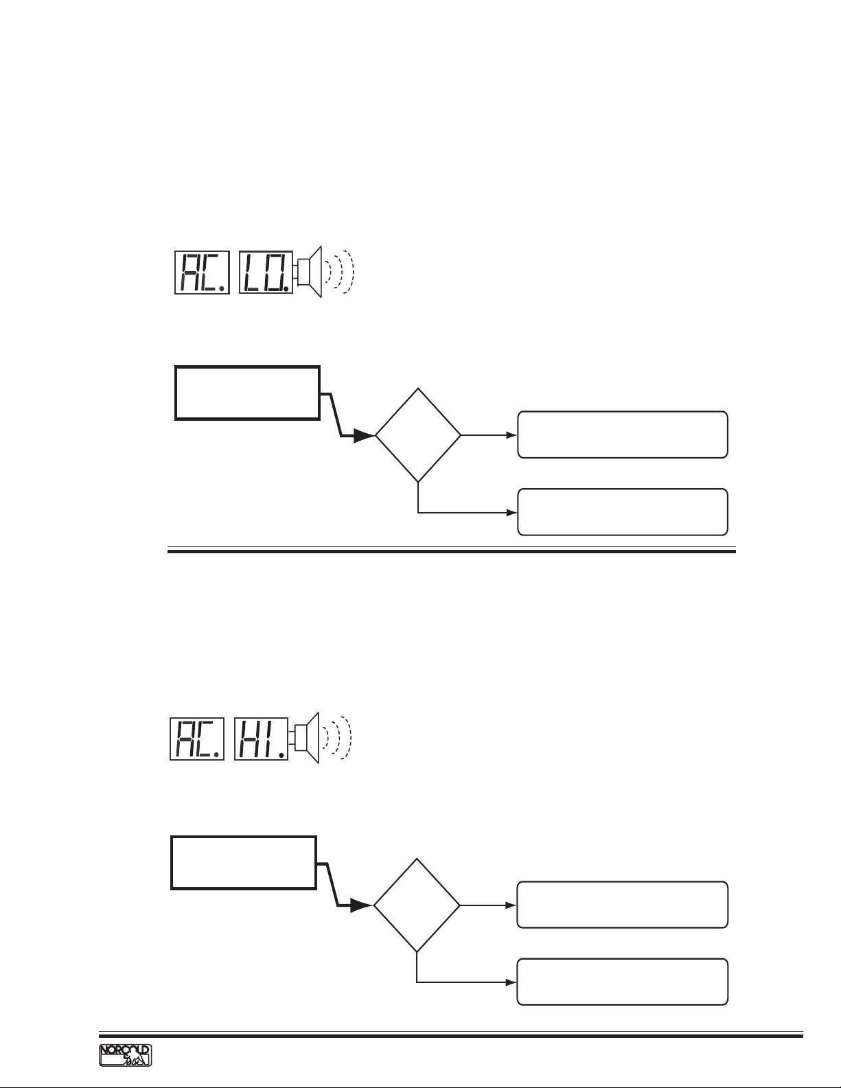
AC LO Fault Code – AC voltage low
Before beginning this procedure:
■
Determine if a certain AC power source sets the AC LO fault code (generator, shore power, inverter).
■
Make sure no other appliance or lighting circuit is connected to the refrigerator AC circuit.
■
Make sure extension cords are not being used to supply AC power to the refrigerator.
Model and indicator displayed.
a
n
t
r
i
A
e
t
l
n
g
le
Audib
D
N64X/N84X
Measure voltage at power
board AC cord connection.
y
i
a
s
l
p
Alarm
Voltage
lower than
108 Vac?
YES
NO
Fault related to RV AC power distribution
component or circuit supplying AC power
to refrigerator.
Replace power board.
AC HI Fault Code – AC voltage high
Before beginning this procedure:
■
Determine if a certain AC power source sets the AC HI fault code (generator, shore power, inverter).
Model and indicator displayed.
a
n
t
r
i
A
l
D
e
t
i
n
g
y
a
s
l
p
N64X/N84X
Measure voltage at power
board AC cord connection.
Audible
Alarm
Voltage
higher than
132 Vac?
www.norcold.com/cda 17N6XX/N8XX ModelsRefrigerator Service Manual
YES
NO
Fault related to RV AC power distribution
component or circuit supplying AC power
to refrigerator.
Replace power board.
Page 21
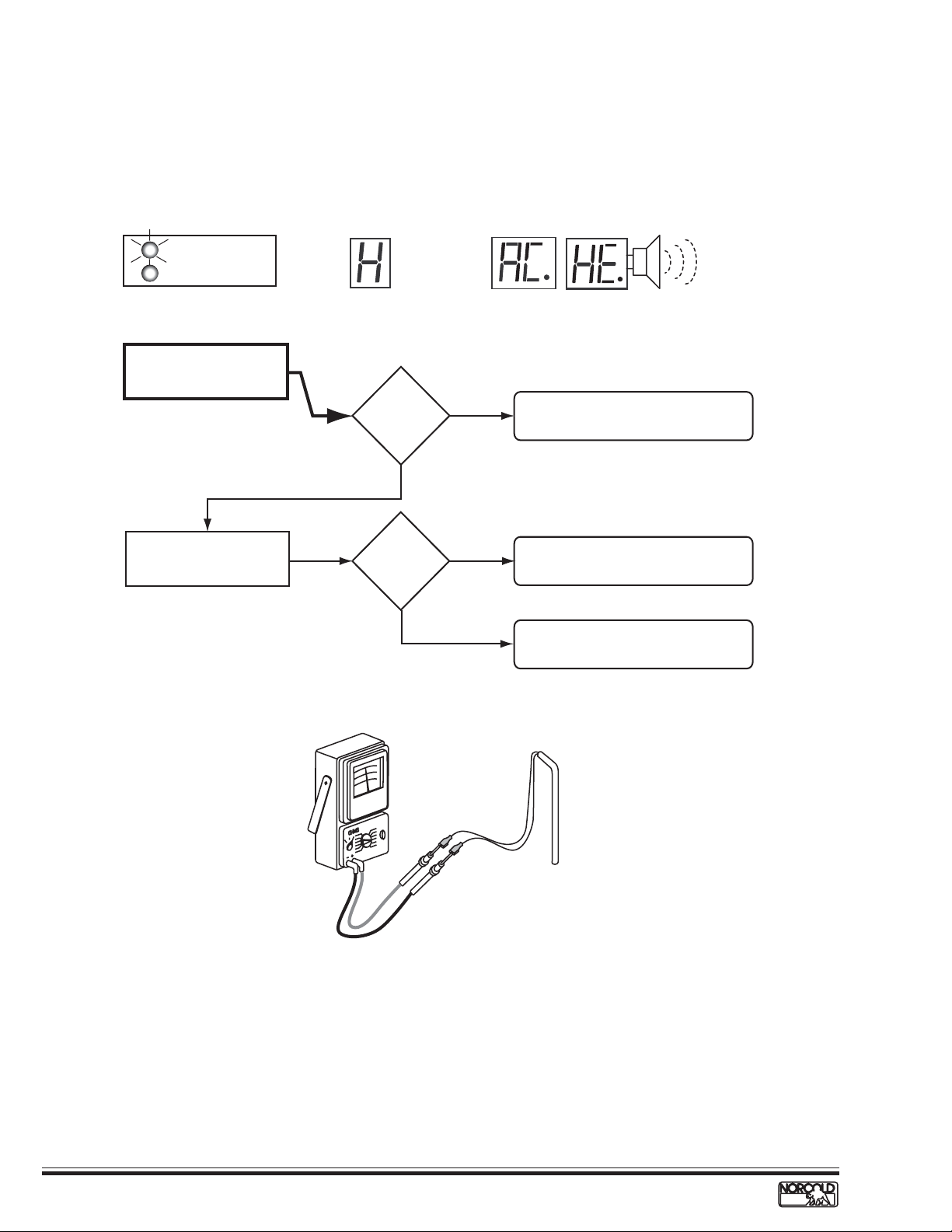
H/AC HE Fault Code – AC heater failed open
Before beginning this procedure make sure:
■
RV AC voltage to the refrigerator is 108 to 132 volts.
■
No other appliance or lighting circuit is connected to the refrigerator AC circuit.
Models and indicator displayed.
a
n
t
r
i
e
t
l
A
ON
Flashin
g 3 tim
es e
very 3 seco
nds
GAS
N61X/N81X
Check AC heater wires for
loose or damaged connector.
AUTO
N62X/N82X
LP GASAC
Heater
connections
okay?
YES
N64X/N84X
NO
D
y
i
a
s
l
p
Repair or replace connectors. If
connectors cannot be repaired,
replace heater.
n
g
Audible
Alarm
Check AC heater resistance.
See See Figure.
Resistance
Ω
38 to 53
NO
?
YES
AC heater resistance 38 to 53
Replace AC heater.
Replace power board.
Ω.
18
www.norcold.com/cda
Refrigerator Service ManualN6XX/N8XX Models
Page 22
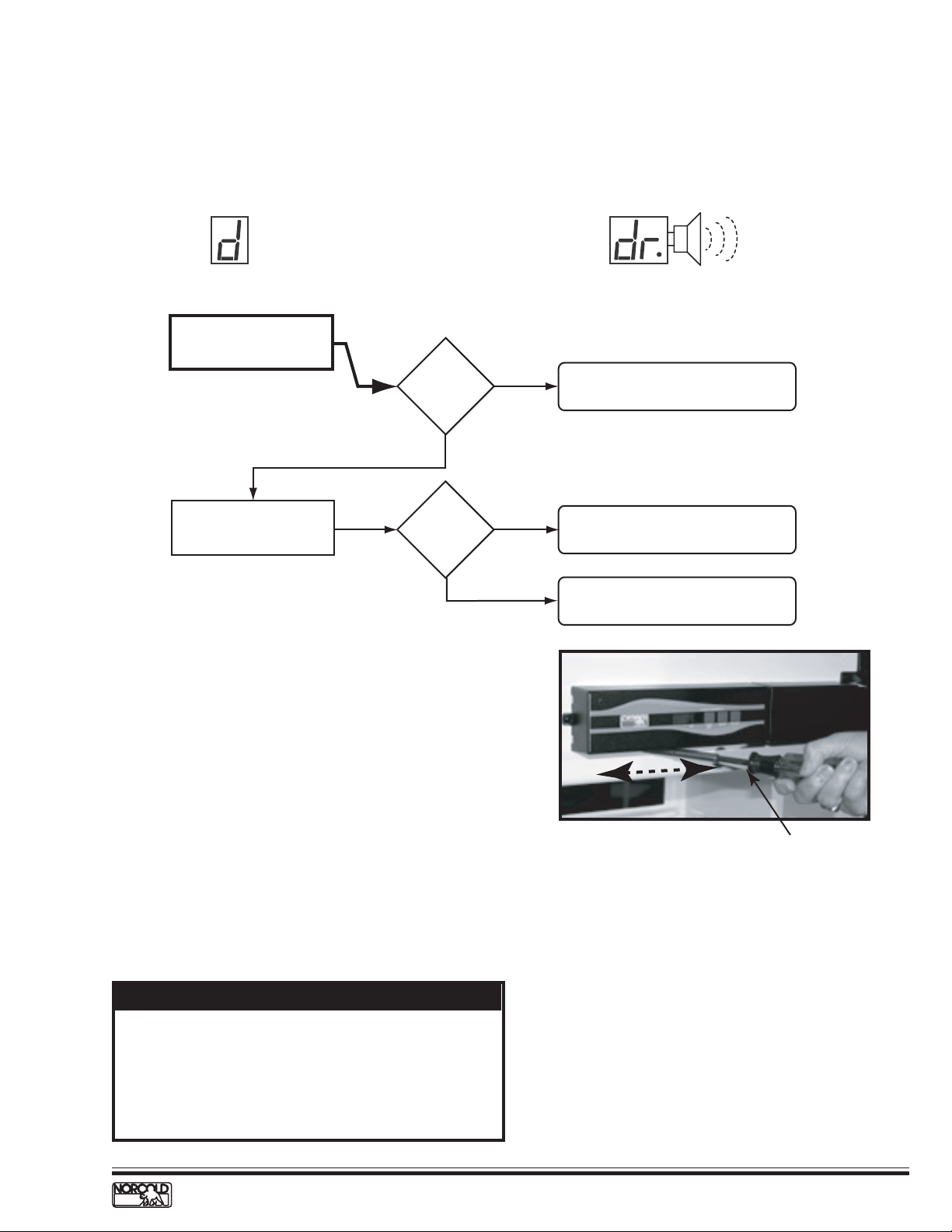
d/dr Fault Code – Door open for more than 2 minutes
Before beginning this procedure make sure:
■
Light/thermistor connector and wire harness connector are fully engaged and locked.
Models and fault indicator displayed.
LAP GASAC
AUTO
N62X/N82X
Check that the door latch
striker plate is adjusted
correctly.
Striker plate
okay?
YES
NO
N64X/N84X
Adjust striker plate.
Audib
Alarm
le
Check for correct door
installation. See NOTE below.
Was door
swing
changed?
YES
Food Compartment Lamp Switch
The reed relay switch that turns the fresh food
compartment light on and off is an integral component
of the optical control display board circuitry .
Lamp Switch Operation
The magnetic pull from a permanent magnet located
underneath the top door trim maintains the switch
contacts open (light off) when the door is fully closed.
Opening the door breaks the magnetic pull, which in
turn causes the switch contacts close (light on).
NOTE
Always follow the instructions provided in the Owner's
Manual to change the refrigerator door swing. The
bottom door trim does not have a magnet. Inverting
the doors will required non-approved modifications and
will cause the fresh food compartment light to remain
on when the door is closed.
NO
Test lamp switch operation. See switch
test procedure below.
Check for location of magnet if the door
swing was changed. See NOTE.
Move tip
Magnetic tip screwdriver
Lamp Switch Testing Procedure
1. Slide a magnetic screwdriver tip or a small magnet
on the underside of the optical control assembly
as shown in the figure above.
2. Check the food compartment light as the
screwdriver tip is moved under the display , the
light:
a. should turn off when the magnetic screwdriver tip
or magnet passes under the optical control
assembly.
b. turn on when the magnetic screwdriver tip or
magnet is distanced from the underside of the
optical control assembly.
3. If the light does not turn off when the magnet
passes under the optical control display , replace
the optical control display assembly .
www.norcold.com/cda 19N6XX/N8XX ModelsRefrigerator Service Manual
Page 23
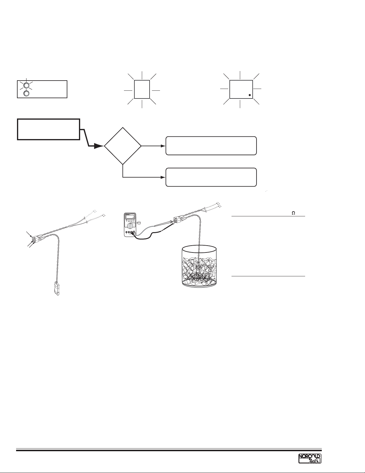
Thermistor Failure Fault – Controls in backup operating system mode
Before beginning this procedure:
■
Make sure lamp/thermistor assembly is connected to wire harness.
Models and fault indicator displayed.
ON
Flash
ing
once every 3 seconds
GAS
N61X/N81X
Check lamp/thermistor wire
assembly and connector for
dirty/broken connections.
Lamp
Connection
Thermistor
Connections
AUTO
Wires and
connector
good?
YES
Temp
Setting
Flashing
LP GASAC
Temp
Setting
Flashing
N64X/N84XN62X/N82X
NO
R
E
T
IME
T
L
U
M
MS
R
E
U
R
T
7
8
III
H
D
L
O
H
E
G
N
A
R
X
A
M
N
I
M
z
H
L
E
R
X
A
M
N
I
M
K
A
E
P
S
T
I
IG
D
2
/
1
4
s
d
n
o
c
e
S
1
mV
mA
A
V
A
µ
V
F
F
O
V
M
O
C
A
µ
A
m
A
!
X
A
M
A
m
0
0
4
I
I
T
A
C
D
E
S
U
F
X
A
M
V
0
0
0
1
X
A
M
A
0
1
D
E
S
U
F
!
Clean/repair terminals or connector as
required. See Figure A.
Check thermistor resistance.
See Figure B and procedure below.
Temperature* Resistance*
(oF) (k )
85 8.1– 9.0
80 9.1–10.0
75 10.1–11.0
70 11.1–12.0
60 12.1–13.0
50 15.5–16.5
40 22.5–23.5
35 24.5–25.5
33 28.5–29.5
32 30.0–32.0
*
Approximate Values
Thermistor
Figure A. Figure B.
Backup Operating System (BOS)
The backup operating system (BOS) is an
electronically controlled duty cycle that maintains the
refrigerator in operation if the thermistor is
disconnected or fails. The BOS maintains cooling by
timing the length of time the heat source is energized.
When the refrigerator is operating in BOS, the length
of the cooling cycle has to be regulated manually
using the TEMP switchbutton.
When a colder temperature is desired, changing the
temperature setting to a higher number provides
additional cooling by lengthening the cooling cycle.
For example, if the temperature setting is set to 5,
raising the setting to 6 will lengthen the cooling cycle.
20
www.norcold.com/cda
Thermistor packed in ice bath
When a warmer temperature is desired, changing the
temperature setting to a lower number shortens the
cooling cycle. For example, if the temperature setting
is set to 6, lowering the setting to 5 will shorten the
cooling cycle.
N61X/N81X Backup Operation.
When the N61X/N81X controls shift to BOS operation,
the ON LED (green) flashes once every three seconds.
N62X/N82XN64X/N84X Backup Operation
When the N62X/N82XN64X/N84X controls shift to BOS
operation, the temperature setting flashes for ten
seconds when the TEMP button is pressed. Af ter ten
seconds, the selected operation mode indicator
displays.
Refrigerator Service ManualN6XX/N8XX Models
Page 24

n/no co Fault Code – No cooling detected by the controls
Models and indicator displayed.
l
A
ON LED flashing
ON
5 times e
GAS
3 seconds
N61X/N81X
Check for cooling at fin
assembly.
very
AUTO
N62X/N82X
Cooling
detected?
YES
LP GASAC
D
N64X/N84X
1. Check for ventilation obstructions
NO
and leveled operation.
2. Reset power board as shown in
figure and described in procedure.
3. Allow unit to operate normally.
a
n
t
r
i
n
e
t
g
Audible
y
i
a
s
l
p
Alarm
Check for completion of
cooling cycle after resetting
power board.
"no" "co"
code shows
before cycle
end?
YES
Power Board Resetting Procedure
1. Turn OFF the refrigerator .
2. Disconnect the following from power board:
a. 12 Vdc positive and negative wires.
b. AC power cord.
c. Solenoid gas valve wires.
d. Spark/sense electrode assembly wires.
3. Remove the power board cover.
4. Reconnect 12 Vdc positive and negative wire.
5. Turn ON the refrigerator.
6. Locate Pin 15 on 16 pin connector (P1). Pin 15 is
the empty socket to the right of the white/violet
wire on the top row. See Figure C.
7. Using an insulated jumper wire, short Pin 15 to the
power board ground lug for 10 - 15 seconds. A click
sound will indicate when the controls are reset.
See Figure C.
NOTE
A jumper wire to short Pin 15 to ground can be made
from a six inch long insulated 22 A WG wire with a 1/2
inch of insulation stripped from each end.
8. Turn OFF the refrigerator .
9. Turn ON refrigerator . If "n" or "no co" code
displays, repeat steps 7 - 9.
NO
White/violet wire
Cooling unit is good. Recheck for
ventilation obstructions and leveled
operation.
1.
Replace cooling unit if "no" "co" shows
before completing a full cooling cycle.
2. Reset power board as shown in
figure and described in procedure.
Pin 16
To pin 15
22 AWG with 1/2" long stripped ends
Insulated wire jumper
Figure C. Resetting Power Board.
10. Turn OFF the refrigerator .
1 1. Disconnect the 12 Vdc power positive and negative
wires from the power board.
12. Install the power board cover.
13. Reconnect the following to the power board:
a. Spark/sense electrode assembly wire.
b. Solenoid gas valve wires.
c. AC power cord.
d. 12 Vdc positive and negative wires from the
power board.
14. Place refrigerator in service.
Ground Lug
www.norcold.com/cda 21N6XX/N8XX ModelsRefrigerator Service Manual
Errata Sheet, 01/16/04
Page 25

VENTILATION
Roof Exhaust Venting
NOTE
The general guidelines for intake vents and roof exhaust
vents presented in this section do not replace the
instructions and/or guidelines provided in the N6XX/
N8XX model refrigerator installation manual and the
Ventilation Guidelines For Gas/Electric Refrigerators,
part number 622090A (3-01). Refer to the N6/N8
installation manual and Ventilation Guidelines For Gas/
Electric Refrigerators for the latest information on
approved vents, installation instructions, and special
construction exceptions.
Air Intake V ent
The ventilation and combustion air flow into the
enclosure through the air intake vent. See Figure 3 and
Figure 4, page 23.
RV front RV rear
Roof exhaust vent
The space between the air intake vent and the rear of
the refrigerator must be kept clear at all times. Any
obstruction in this area may cause serious ventilation
problems. The air intake vent opening is also the
access for servicing cooling unit components.
Roof Exhaust Vent
The heat absorbed by ventilation air and combustion
gases flow out of the enclosure through the roof
exhaust vent. See Figure 3 and Figure 4, page 23.
The roof exhaust vent is equipped with non removable
metal mesh screen that prevent leaves, debris, birds or
rodents from getting into the enclosure. The roof cap is
fastened to the exhaust vent with four screws. The cap
is always installed with the slope towards the front of
the RV.
Exhaust vent screen
Baffle
Full width of enclosure
to isolate the top of refrigerator
from rejected heat
Condenser
1/8 inch maximum
if wider (see Figure 4)
Absorber coils
1/4 inch
or less
22
1 inch maximum.
If wider, see Figure 5.
Intake vent
Figure 3. Roof Exhaust Venting Arrangement.
www.norcold.com/cda
Refrigerator Service ManualN6XX/N8XX Models
Page 26

Top baffle
r
Required when the
clearance from the
underside of the roof
to the top of the refrigerato
exceeds 1/4 inch.
Condenser
Side wall baffles
Required when the
clearance between the
enclosure side walls
and refrigerator
exceeds 1/8 inch.
Absorber coils
Intake vent
Figure 4. Rear View–Roof Exhaust Venting.
Baffles
The minimum and maximum clearances for installing
the refrigerator or correcting ventilation problems on
roof vented units are listed in Table 1. Baffles are
required whenever installations exceed maximum
clearances listed in Table 1. Figure 4 shows baffle
locations.
Vertical Angled Baffles
Vertical angled baf fles are required when the roof
exhaust vent is installed inboard of the condenser .
Figure 5 shows the angled vertical baffles required on
inboard roof vent installations. The horizontal wall
baffles are required whenever the distance between the
cooling unit and the interior surface of the outside wall
exceeds one inch.
Minimum Maximum
Bottom 0 inch 0 inch
Sides (each) 0 inch 1/8 inch
Top 0 inch 1/4 inch
Angled baffles
Required when the
roof exhaust vent
is inboard of
the condenser.
1/4 inch
or less
Condenser
Baffles
Required when
the opening between
the outside wall and
cooling unit is over
1 inch.
Air intake vent
Rear 0 inch 1 inch
Table 1. Clearances for Roof Vented Installations.
www.norcold.com/cda 23N6XX/N8XX ModelsRefrigerator Service Manual
Figure 5. Baffles Required for an Inboard
Roof Exhaust Vent Inst allation.
Page 27

Double Sidewall Venting
NOTE
The general guidelines for intake vents and roof exhaust
vents presented in this section do not replace the
instructions and/or guidelines provided in the N6XX/
N8XX model refrigerator installation manual and the
Ventilation Guidelines For Gas/Electric Refrigerators
part number 622090A (3-01). Refer to the N6XX/N8XX
installation manual and Ventilation Guidelines For Gas/
Electric Refrigerators for the latest information on
approved vents, installation instructions, and special
construction exceptions.
With increased installation of refrigerators in RV slide
outs. NORCOLD has conducted extensive testing to
develop venting guidelines for double sidewall vent
applications. This work was done to ensure NORCOLD
refrigerators meet the ANSI Z21.19 standards for
cooling performance when used in slide out
applications.
The challenge with slide out installations is that the
"chimney effect" that is present with roof vent
installations is not as strong in slide outs. To improve
the "chimney effect" side vent installations must have
fans and baffles. These fans and baffles direct the air
flow through the surfaces of heat rejecting
components. NORCOLD has determined that the
following three key design considerations optimize
heat removal in slide out applications.
An additional challenge with double sidewall venting is
the depth of the enclosure. The deeper the enclosure,
the greater the impact on the air flow through the rear
of the refrigerator. Taking the three key design
considerations and the variable depth requirement into
account, NORCOLD developed and tested several
baffle arrangements for the N6XX and N8XX models
versus their ability to meet the ANSI st andards.
As the result of this testing, NORCOLD was able to
reduce the baffle configuration down to two baffles for
the N6XX and N8XX models. It should be noted that
baffle arrangements are different if the enclosure depth
is greater or less than 26 inches. The baffle
configurations are shown in Figure 6, page 25, and
Figure 7, page 26.
Air Intake Vent
The ventilation and combustion air flow into the
enclosure through the air intake vent. See Figure 6,
page 25 and Figure 7, page 26.
Sidewall Exhaust Vent
The heat absorbed by ventilation air and combustion
gases flow out of the enclosure through the sidewall
exhaust vent. See Figure 6, page 25, and Figure 7,
page 26 for details.
n Refrigerators installed in slide outs must have a fan
or fans to assist air flow. Fan kits and refrigerators
with factory installed fan(s) are available from
NORCOLD.
n Fresh air must be directed to flow through the
surface areas of the absorber coils, condenser fins,
and the outer surface of the canister.
n Corners and structural pockets where heated air
may stagnate must be reduced in size or
completely eliminated.
24
www.norcold.com/cda
Refrigerator Service ManualN6XX/N8XX Models
Page 28

Figure 6. Baffle Arrangement for Enclosures Depths of More than 24 Inches and Less than 26 Inches.
www.norcold.com/cda 25N6XX/N8XX ModelsRefrigerator Service Manual
Page 29

Figure 7. Baffle Arrangement for Enclosures with Depths of 26 Inches or Greater .
26
www.norcold.com/cda
Refrigerator Service ManualN6XX/N8XX Models
Page 30

DC connections
Gas valve
Burner tube
LP GAS SYSTEM
Canister
Flue tube
Baffle
Gas inlet fitting
Gas outlet fitting
Pressure
test port
When working on or near the LP gas system:
n Do not smoke or light fires! Extinguish all open
flames!
n Do not use an open flame to leak test any of the
LP gas system components. LP gas is highly
flammable and explosive.
Manual shut-off
(shown closed)
!
WARNING:
RV
LP gas supply
Figure 8. LP Gas System Components.
Electrode
Burner
Orifice assembly
(LP16 orifice shown)
Burner box base
Testing for LP Gas LeaksPressure Requirements
!
WARNING:
Do not wet or spray liquids on or near electrical
connections or electronic components. Many liquids,
including leak detection solutions, are electrically
conductive and can create an electric shock hazard,
short electrical components, and/or damage electronic
circuits.
n Do not connect the refrigerator directly to the LP
gas tank. Always use an approved pressure
regulator between the LP gas tank and the
refrigerator LP gas system.
n To prevent damage to connections, piping, and
components, always use two wrenches to tighten
or loosen connections. Damaged connections,
piping, and components create the potential for
gas leaks.
The refrigerator LP gas system, shown in Figure 8, is
for propane gas use only . The system working
pressure is 10.5 and 1 1.5 in. water column. Propane
gas pressures below 10.5 in. w.c. or above 11.5 in.
w.c. will af fect heat output which in turn will af fect
cooling efficiency . Propane gas flow control is
monitored by electronically by the controls flame
sensing circuit. If the flame sensing circuit does not
detect a burner flame within 30 seconds after initiating
ignition, power to the gas valve is turned off and gas
mode is locked out.
!
CAUTION:
Do not use leak test solutions that contain ammonia
or chlorine. Ammonia and chlorine attack copper and
brass components.
Leak testing can be accomplished using an electronic
leak detector or a commercial grade leak test solution.
The use of home made soap and water leak test
solution should be avoided if possible. When applying
leak test solutions, apply the solution over the entire
joint using a small brush or spray applicator.
Due to low system operating pressure, it may take a
few minutes for bubbles to appear if the connection is
leaking. Hidden joints should be examined thoroughly
using an inspection mirror.
www.norcold.com/cda 27N6XX/N8XX ModelsRefrigerator Service Manual
Errata Sheet, 01/16/04
Page 31

Components
When working on the refrigerator LP gas system:
DC connecti ons
Mounting bracket
n Do not alter or modify the burner tube anti-vibration
loop.
n Do not cross thread fittings. Exercise extreme care
when connecting and disconnecting propane gas
components.
n Leak test all of the refrigerator propane gas system
fittings after servicing, replacing, or repairing any
LP gas system component.
Solenoid Gas Valves
Units with serial number 657908 or higher
(manufactured on or after February 16, 1999) are
equipped with the new style solenoid gas valve . See
Figure 9.
Units with serial numbers lower than 657908, (models
manufactured before February 16, 1999) are equipped
with the old style solenoid gas valve. See Figure 10.
The electronic controls automatically operate the
solenoid gas valve.
New Style Solenoid Gas Valve
The new style solenoid gas valve manual shut off and
pressure tap are integrated in the valve’s body . The
valve's manual shut-off is a spring-loaded, quarter turn
manually operated valve.
T o manually shut-of f gas to the burner , pull the handle
slightly away from the body , then turn it one-quarter
turn (90 degrees) counterclockwise.
Old Style Solenoid Gas Valve
Refrigerators with serial numbers lower than 657908,
(models manufactured before February 16, 1999) are
equipped with the old style solenoid gas valve. See
Figure 10.
Solenoi d
Gas inl et
Gas outl et
fi tti ng
Gas pressure
test port
Manual shut-off
fi tti ng
(from RV
LP gas)
(shown c l osed)
Figure 9. New Style Solenoid Gas Valve.
Solenoid
Gas valve
DC connections
Gas
pressure test port
Gas outlet
fitting
Gas inlet
fitting (from
RV LP gas system)
Use a NORCOLD® gas valve conversion kit, part
number 621334, to replace an old style solenoid gas
valve assembly .
Solenoid Gas Valve Connections
The solenoid gas valve inlet fitting is 3/8 inch, male
threads; the outlet fitting is 1/4 inch, male threads.
28
www.norcold.com/cda
Manual shut-off
(shown open)
Mounting bracket
Figure 10. Old Style Solenoid Gas Valve.
Refrigerator Service ManualN6XX/N8XX Models
Page 32

Orifice
The orifice controls the flow of propane gas to the
burner. When replacing the orifice always use the size
orifice specified. Using the wrong size or a damaged
orifice will alter the amount of propane flowing to the
burner.
N62X/N64X units with serial number 886961 and higher
and N82X/N84X units with serial number 889988 and
higher are equipped with an LP16 cap type orifice. All
other units with serial numbers lower than those listed
were originally equipped with an 0.155 jeweled orifice.
See Figure 1 1.
!
WARNING:
Do not separate cap style LP16 orifice from its adapter .
Separating the assemblies breaks the seal and
causes an LP gas leak.
!
WARNING:
Do not use compressed air to clean a jeweled type
orifice. The air pressure may dislodge the orifice from
the adapter.
0.155
0.155 Jeweled orifice assembly
1
P
L
6
Cap type LP16 orifice assembly
Figure 11. 0.155 and LP16 orifice assemblies.
!
CAUTION:
Do not install cap style LP16 orifice in a burner that
uses a jeweled type orifice or vise versa. The orifice
adapter's threads are not compatible. Each orifice
must be matched to its burner .
Burner
The burner, see Figure 12, provides primary air access
and acts as the fuel mixing chamber to support
ignition and the combustion of propane gas. Primary
combustion air flows into the burner through three
circular openings. Any obstruction blocking any of the
three openings will have an effect on the fuel/air
mixture. Insufficient combustion air will cause carbon
deposits to clog the burner slots. Carbon clogged
burner slots along with heavy dirt deposits in the
burner are the main cause of no cooling or poor
cooling performance when the refrigerator is operating
in LP gas mode.
Burner Tube
The burner tube is 1/4 inch OD aluminum tubing with
an anti-vibration loop and a double flare at each end.
See Figure 13.
Figure 12. Burner.
Burner connection
Gas valve connection
Figure 13. Burner tube.
www.norcold.com/cda 29N6XX/N8XX ModelsRefrigerator Service Manual
Page 33

Flue
The flue on all N6XX/N8XX terminates a few inches
above the canister. See Figure 14. The flue comes
equipped with a removable baffle ("spiral baffle") and a
metal heat deflector .
The flue and its components should be checked
annually . In roof exhaust venting applications, the
refrigerator must be removed from the enclosure to
check or service the flue or any of its components.
In most sidewall exhaust venting applications, removal
of the side wall exhaust vent provides clear access to
service the flue or any of its components.
A one inch diameter , loop-handle, twisted wire brush
with a 27 inch wire handle is recommended for
sweeping clean the flue.
Heat Deflector
The heat deflector, see Figure 14, deflects hot exhaust
gases to the sides. It also keeps dirt and debris from
getting into the flue. Cooling performance may be
affected if the heat deflector is not installed or is not
installed correctly .
Spiral Baffle
The spiral baffle, see Figure 14, traps and transfers
heat to the cooling unit generator.
Heat deflector
Flue
Baffle retaining
wire
Baffle
Burner box
Figure 14. Flue and Components.
Retaining wire
A retaining wire suspends the spiral baffle in the flue
just above the flame. See Figure 15. The spiral baffle
should be checked annually . To remove the spiral
baffle from the flue:
1. Remove the heat deflector.
2. Unclip the baffle retaining wire from the rim of the
flue.
3. Pull the baffle out of the flue tube.
!
CAUTION:
Do not cut or modify the spiral baffle retaining
wire! The wire positions the baffle for optimal heat
transfer.
Flame Appearance
The flame should be light blue with sharp blue root
cones and a steady burning flame plume. See Figure
16.
A flame that is mostly orange or yellow, is erratic, and
unstable, indicates a "dirty" burner . Burner cleaning
procedures appear on page 30.
Baffle
Figure 15. Flue Baffle.
Light blue steady flame
with sharp blue cones
30
www.norcold.com/cda
Figure 16. Flame Appearance.
Refrigerator Service ManualN6XX/N8XX Models
Page 34

Burner Cleaning Procedure
!
WARNING:
Burn hazard! Allow the burner box and burner
components to cool before attempting to service the
burner assembly or components.
!
CAUTION:
Do not use compressed air to clean a jeweled type
orifice. The air pressure may unseat the jewel orifice
insert from the adapter.
1. Turn OFF power to the refrigerator .
2. Close the LP gas tank valve.
Step 3 through Step 5, refer to Figure 17, page 32
3. Close the combination gas control valve manual
shut-off.
4. Remove the drip cup.
!
CAUTION:
To prevent damage to connections, piping, and
components, always use two wrenches to loosen the
burner tube. A damaged burner tube creates a
potential for gas leaks.
5. Remove the burner box cover.
Step 6 through Step 8, refer to Figure 18, page 32
6. Disconnect the burner tube from the orifice
assembly.
7. Remove the orifice assembly from the burner.
8. Remove the burner retaining screw.
9. Remove the burner from the burner box frame.
10. Clean the burner .
NOTE
The burner slots may be cleaned with a small flat
file. The inner bore of the burner body may be cleaned
with a 3/16 in., double-spiral wire brush. Do not
damage the threads when cleaning the inner bore of
the burner.
11. Visually inspect the orifice. If dirty , wash the
assembly with alcohol then allow to air dry.
Replace the orifice assembly if the cleaning fails to
remove dirt or if the condition of the orifice
assembly is questionable.
12. Clean any accumulation of dirt or debris from the
burner box base.
13. Reinstall the burner. Do not over tighten the
burner's retaining screw.
!
CAUTION:
To avoid gas leaks and prevent damage to
connections, piping, and components, always use
two wrenches to tighten the burner tube. A damaged
burner tube creates a potential for gas leaks.
14. Install the orifice assembly. First thread the orifice
assembly into the burner finger tight, then finish
tightening using two wrenches.
15. Connect the burner tube. First thread the fitting
finger tight, then finish tightening using two
wrenches.
16. Install the burner box cover. Do not overtighten the
cover retaining screw.
17. Open the LP gas tank valve.
18. Open the solenoid gas valve manual shut-off.
19. Turn ON the refrigerator and select LP manual
mode operation.
20. Leak test LP gas connections during the 30
second trial-for-ignition.
NOTE
Do not insert any type of cleaning tool or wire into the
orifice. Do not drill or ream the orifice opening to clean
it. Insertion of any type of cleaning tools, reaming, or
drills through the opening will alter the volume of LP
gas flow to the burner and create a fire hazard potential.
www.norcold.com/cda 31N6XX/N8XX ModelsRefrigerator Service Manual
!
WARNING:
Do not attempt to repair LP gas leaks with the
refrigerator in operation. Before attempting to repair a
gas leak:
n Turn OFF the refrigerator .
n Close the LP gas valve and the solenoid gas valve
manual shut-off.
Page 35

Figure 17. Drip Cup and Burner Box Cover.
r
32
Baffle
Burner
tube
Orifice adapter with LP16 orifice
Flue
Figure 18. Burner and Components.
www.norcold.com/cda
Caniste
Electrode
Burner
Refrigerator Service ManualN6XX/N8XX Models
Page 36

ELECTRICAL REQUIREMENTS AND COMPONENTS
DC Voltage Requirements and Polarity
Operating controls require 10.5 to 15.4 Vdc to operate.
The positive wire lead (+) connects to power board
terminal 12VDC; the negative wire lead (–) connects to
terminal GND1.
Power Board DC Fuse
!
WARNING:
Never replace a fuse with a higher amp rated fuse.
Always use the specified fuse.
The controls circuit fuse is a standard 5 amp (tan
color) automotive blade type fuse. It is located on the
power board, terminal F1.
DC Power Wiring Requirements
!
WARNING:
Never use undersized wires to supply DC power to
the power board. The use of undersized wires can
cause low voltage and high amp draw conditions. The
high amp draw caused by a circuit using undersized
wires will cause the wire to overheat and creates an
electrical fire hazard.
DC Heater–3-Way Refrigerators Only
!
WARNING:
Do not wire the heater(s) direct! Wiring heater(s)
direct bypasses control safety devices and creates
the potential for an electrical fire.
The DC heater, shown in Figure 19, is a cartridge type
heater. The DC heater is rated for 225 W atts/16 amps,
at a nominal 14 Vdc. Heater resistance should be
0.82 - 0.91 ohms.
NOTE
The AUTO DC and DC-Manual Mode operation
maintain refrigeration only .
Stop Bead
2-Way Models
18 AWG is the minimum AWG size wire that can be
used for connecting DC power to 2-way models. The
size fuse for overload protection must not exceed 6
amps.
3-Way Models
The distance between the RV DC power source and
the power board DC power connection terminals
dictates the AWG size wire that must be used. If the
distance from the DC power source is:
n 20 feet or less – 10 AWG or a larger gauge wire
must be used. The size fuse for circuit overload
protection must not exceed 30 amps.
n Over 20 feet – AWG 8 or a larger wire gauge must
be used. The size fuse for circuit overload
protection must not exceed 40 amps.
AC/DC Converter as Power Source
The power board must be supplied 12 Vdc only from
the filtered output (battery side) of a converter.
Unfiltered voltage (commonly referred to as AC ripple)
output of AC/DC converters can cause the electronic
controls to set false fault codes. It can also turn off the
refrigerator or prevent the refrigerator from turning off.
Y ellow Wire Leads
Figure 19. DC Heater
When AUTO DC or DC-Manual Mode does not
maintain refrigeration and ventilation is correct:
n Measure DC voltage input to the power board.
n Measure the heater's amp draw.
n If amp draw is not as specified, measure the
heater's resistance at ambient temperature.
The DC heater must be inserted into the heater tube
until the stop bead makes full contact with the tube's
rim. See Figure 20, page 34.
DC Heater Circuit Fuse
!
WARNING:
Never replace a fuse with a higher amp rated fuse.
Always use the specified fuse.
The DC heater circuit fuse is a standard 30 amp
(green) automotive blade type fuse. It is located on the
power board, terminal F2.
www.norcold.com/cda 33N6XX/N8XX ModelsRefrigerator Service Manual
Page 37

AC Power Requirements
DC Heater
AC Heater
AC Heater Tube
DC Heater Tube
Canister Door
Figure 20. AC and DC Heaters (3-way refrigerator)
Lamp Assembly
The operation of the fresh food compartment 12 Vdc
lamp is controlled by a magnet activated reed relay
switch. The switch is in the optical control circuit
board and the magnet is permanently mounted on the
underside of the door's top trim piece.
Leaving the door ajar or open for more than two
minutes causes the controls to display a "d" or "dr"
fault code (depending on unit model). Closing the door
turns off the light and clear the "d" or "dr" fault
indicator from the display . However , the fault code will
be stored in the diagnostic mode nonvolatile memory .
For "d"/"dr" troubleshooting procedures. See page 19.
As shown in Figure 21, the light assembly harness
and thermistor share the same connector. Remove the
light cover to access the connector.
!
WARNING:
Electric shock hazard! The refrigerator is fed power
from more than one source. Unplug the AC cord from
the RV AC receptacle before servicing electrical or
electronic components.
AUTO AC and AC-Manual Mode operation requires 108
to 132 V ac. AC power must be supplied through a 2
pole/3 wire/20 amp grounding type receptacle.
AC Heater
!
WARNING:
Do not wire the heater(s) direct! Wiring heater(s)
direct bypasses control safety devices and creates
the potential for an electrical fire.
The AC heater, see Figure 22, is a cartridge type
heater. Refrigerators with serial number lower than
854647 heater is rated for 300 Watts/2.7 amps @ 110
V ac and has a resistance of 41.25 ohms. Refrigerators
with serial number 854647 and higher heater is rated
for 300 Watts/2.5 amps @ 120 Vac. Heater
resistance is 48 ohms.
Connector
Clip
Thermistor
Light bracket
Lightbulb
Light cover
N641/N841
Figure 21. Lamp/Thermistor Assembly .
Divider Heater
The divider heater is permanently "foamed" between
the divider separating the freezer and fresh food
compartment. The controls constantly monitor power
board voltage output to the heater through built in
diagnostics. Turning the refrigerator on automatically
powers the heater.
Stop Bead
Black Wire Leads
Figure 22. AC Heater.
When poor or no cooling in AUTO AC or AC-Manual
Mode, operation is present:
1. Measure AC voltage input to the power board.
2. Measure heater amp draw.
3. If amp draw is not as specified, measure the
heater's resistance at ambient temperature.
When replacing an AC heater make sure the stop bead
rests fully against heater tube rim. See Figure 22.
AC Heater Circuit Fuse
1
The AC circuit fuse is a fast acting 5 amp
/
" x 1
4
1
/
"
4
AGC type. It is on the power board, terminal F3.
34
www.norcold.com/cda
Refrigerator Service ManualN6XX/N8XX Models
Page 38

AC Power Cord
The AC power cord shown in Figure 23(a) is used on
units without ice maker . On all AC power cords the
round side of the plug that connects to the power
board faces the left side of the power board. The cord's
grounding prong on the AC outlet connector must be
left intact and never be modified or cut. The cord's
ground wire (green wire) must always be fastened to
the refrigerator cabinet metal plate.
Power Cord for Ice Maker Units
The AC power cord shown in Figure 23(b) is used on
N64X IM and N84X IM units (IM = ice maker). The cord
has two short wire leads originating at the rear of the
power board connector plug to connect the ice maker
wire harness black and white leads. The short ribbed
wire is the line voltage lead, it has a female quickconnect type terminal. The smooth wire is the neutral
lead, has a male quick-connect type terminal. Refer to
pages 71 and 72 for ice maker wiring pictorials and
diagrams.
All N643IM and N843IM units are equipped with an
independent AC power cord (white in color) to supply
120 Vac to the ice maker only.
(b)
Smooth black lead
(a)
REFRIGERATORS WITH ICE MAKERS
Ground wire
REFRIGERATORS WITHOUT ICE MAKERS
to black ice maker wire
Ribbed black lead
to white ice maker wire
Ground wire
Figure 23. AC Power Cord.
Fan mounting screws
12 Vdc V entilation Fan
The 12 Vdc ventilation fan, shown in Figure 24,
enhances ventilation in sidewall venting installations
(unit installed in RV slide out enclosures). The letter
"F" in a model number is used to identify refrigerators
with a factory installed 12 Vdc ventilation fan. All
sidewall vented units must be equipped with a
ventilation fan to prevent combustion gases and hot
ventilation air from stagnating in the enclosure.
Ventilation fans are supplied 12 Vdc through power
board connections. Fan operation is automatically
controlled by a thermostatic switch mounted on the
first condenser fin. See Figure 25. The switch turns the
fan on when the temperature on the first condenser fin
is approximately 130 °F. The switch turns the fan off
when fin temperature falls to approximately 1 15 °F.
NORCOLD® fan kit is wired to the power board 12 Vdc
connections using "Y" type wire connector. The fan
circuit is protected by an in-line fuse (included in the
kit). The fuse, part of the fan kit wiring is a fast acting
1
1 amp,
pictorial for field installed fan is shown in Figure 27,
page 36.
/4” x 11/
” AGC type. See Figure 26. The wiring
4
Outer bracket and mounting screws
Figure 24. Fan Mounted on Top of Absorber Coil.
+ 12 Vdc input to thermostatic switch
Fan thermostatic switch
+12 Vdc wire to fan connection
Figure 25. Fan Thermostat.
www.norcold.com/cda 35N6XX/N8XX ModelsRefrigerator Service Manual
Page 39

Red wire to thermal
switch
Red w
Fan thermostatic
switch
Red
n
fa
to
ire
Wire
THERMOSTAT
Red
Wire
Black
Fan
Wire
Red
Fan
Fan
1AMP
FUSE
Red Spliced Wire
Wire
FAN
Black Spliced Wire
Black
Wire
1 amp
in-line fuse
+ 12 Vdc connection
- 12 Vdc connection
Installed NORCOLD Fan Kit.
POWER BOARD
12 VDC
GND1
12 Vdc12 Vdc
Figure 27. NORCOLD Fan Kit Wiring Pictorial.Figure 26. Fan with Wiring Arrangement for Field
36
www.norcold.com/cda
Refrigerator Service ManualN6XX/N8XX Models
Page 40

COOLING UNIT
Description
The cooling unit is a self-contained gravity flow
absorption refrigeration system. The refrigerant charge
is a solution of water, ammonia, sodium hydroxide,
and sodium chromate (a corrosion inhibitor).
Refrigeration is accomplished by applying heat energy
and venting the heat extracted from the freezer and
fresh food cabinet while maintaining the unit leveled.
Heat Absorption
The refrigerant transfers the heat from the freezer and
the food cabinet to the absorber coils. At the absorber
coils the metal surface absorbs the heat and air flow
over the external surfaces of the coils and carries
away the heat. A thermal air current created by the
rising hot air flows out of the enclosure through the
roof exhaust vent or sidewall exhaust vent (depending
on installation). The flowing air mass passes over the
surface of the condenser fins where it absorbs heat
transferred from the ammonia vapors flowing through
the condenser.
The thermal airflow process creates a "chimney
effect". The "chimney effect" creates a continuous
draft of cooling and combustion air. The fresh air
drafted by the "chimney effect" though the intake vent
removes rejected heat, support combustion, and
expels the exhaust gases produced by the combustion
process. Obstructions, restrictions, or modifications to
vents or the enclosure will affect the heat absorption
cycle. Poor cooling unit performance may be due to:
n Loose insulation interfering with the ventilation
process.
n Construction material or debris left in the
enclosure.
n Insect screen covering vents.
n Plastic sheeting covering vents.
n Items stored in the enclosure.
n Modifications to vents or enclosure.
n No roof or sidewall exhaust vent opening.
Information pertaining to ventilation and enclosure
requirements appears on page 22.
Leveled Operation
The circulation of the refrigerant through the cooling
unit is accomplished by gravity flow; therefore, the
refrigerator must be operated leveled. Off-level
operation affects the flow of the refrigerant through the
cooling system. The maximum off-level operation limits
are:
n 3 degrees from side-to-side.
n 6 degrees from front-to-back.
Exceeding the maximum off-level limits can
permanently damage the cooling unit.
The cooling unit or its performance are not affected
when the vehicle is in motion
Gradual Decrease in Cooling Efficiency
A gradual decrease in cooling efficiency is not a clear
indication of cooling system failure. Other factors that
affect cooling efficiency include ventilation, the heat
input, off-level operation, lack of service and
maintenance, inadequate repairs, or unauthorized field
modifications. If any of these factors exist and are not
corrected, a replacement cooling unit will also perform
inefficiently or fail.
Step-by-step troubleshooting is the best approach
when dealing with a gradual decrease in cooling. It is
important to consider is that, though not efficiently, the
cooling unit is working. Troubleshooting should always
begin by checking ventilation, then thoroughly
checking the cooling unit, and heat sources. In the
majority of reported case, the problem has been
related to the installation, which in turn hindered
cooling unit ventilation.
Additionally, ambient air temperature plays a
significant role if the unit was not installed correctly.
Incorrect installation lead to poor ventilation, which in
turn relates to poor cooling performance.
The unit's service and maintenance history should be
considered when checking a cooling unit for poor
cooling performance. The service history and the
scope of service work performed may lead directly to
cause and resolution of a cooling problem.
The cooling unit has to reach normal operating
temperatures before troubleshooting can take place. It
takes an average of four hours for the refrigerant to
reach normal operating temperatures. The time frame
to reach operating temperatures depends on ambient
air temperature.
Cooling System Monitoring
The controls monitor cooling system performance
when a heat source is active. If the controls sense that
.
the system is not cooling, it displays a fault code ("n"/
"no" "co") and locks out all heat energy sources.
First "No Cooling" Fault Occurrence
Users can reset the controls by turning the refrigerator
off then back on. The user resetting option can only be
accomplished when the controls record the first "no
cooling" ("n"/"no" "co") fault occurrence. The
completion of a full cooling cycle will remove the
recorded first "n"/"no" "co" fault from memory and
returns the controls to normal monitoring operation.
T wo Recorded "No Cooling" Fault Occurrences
If the controls detect two consecutive recorded "no
cooling" faults , the "n"/"no" "co" fault code displays
and the controls will lock out all heat sources (AC/LP/
DC). The power board can then only be reset by an
authorized service center after troubleshooting and
testing cooling system operation. See Page 21.
www.norcold.com/cda 37N6XX/N8XX ModelsRefrigerator Service Manual
Page 41

Troubleshooting Cooling Faults
A high percentage of cooling units returned labeled
“faulty” are fully operational units. The flowchart on
page 38 provides information to troubleshoot cooling
unit related faults.
Poor or No Cooling on AC Mode
!
WARNING:
Do not work on live circuits! Turn off and disconnect
AC power and DC power supplies before attempting
to remove, service, or repair any of the refrigerator's
electrical or electronic circuits or components.
When troubleshooting poor or no cooling in AUT O AC
or AC-Manual Mode, first check AC volt age input to the
power board, then check voltage output to the heater ,
and the heater's amperage draw.
AC voltage problems, high or low volt ages, caused by
the RV AC power supply circuit. To troubleshoot AC
faults, refer to the diagnostic flow charts on pages 16,
17, and 18 of this manual.
Poor or No Cooling on LP Gas Mode
Poor or No Cooling on DC Mode – 3-Way Models
!
WARNING:
Do not work on live circuits! T urn off AC power and
DC power before attempting to remove, service, or
repair any of the refrigerator's electrical or electronic
circuits or components.
When troubleshooting poor or no cooling in AUT O DC
or DC-Manual Mode, always check DC voltage input to
the power board, voltage output to the heater , and
heater amperage draw. If DC volt age input to the
refrigerator is lower than 12 Vdc, the problem is
usually related to the DC power supply source. The RV
DC power supply source may not be supplying the
correct voltage to the power board.
The diagnostic flowcharts on pages 13, 14, and 15 of
this manual provide information to troubleshoot DC
power faults.
!
WARNING:
Do not operate the refrigerator if the cooling unit is
leaking or leakage is suspected.
!
WARNING:
LP gas (propane) is highly flammable and
explosive! Do not smoke, light fires, or create sparks
when working on the LP gas system.
Do not use an open flame to leak test any propane
gas system component.
When troubleshooting poor or no cooling in AUT O LP
mode or LP-Manual Mode, always check the burner
flame appearance first. Most faults on LP gas
operation related to a "dirty burner."
The diagnostic flowchart on page 12 of this manual
provides information to troubleshoot the no flame
faults.
Refrigerant Leakage
Y ellow powder or liquid deposits at the rear of the
refrigerator or ammonia smell inside the refrigerator
indicate refrigerant leakage. Exercise extreme care
when handling a leaking or a suspected leaking
cooling unit. The cooling system refrigerant solution
consists of water , ammonia, sodium hydroxide, and
sodium chromate.
Disposal of Cooling Unit
Dispose of cooling unit according to local, state, and
federal guidelines and regulations. Dispose of any
liquid waste or residue, according to pre-emergency
planning and all applicable local, state, and federal
regulations.
Do not, under any circumstances, release any waste
or residue directly into sewers, or surface waters. If
any liquid leaks or spills from the cooling unit, contact
the nearest environmental services for guidance.
38
www.norcold.com/cda
Refrigerator Service ManualN6XX/N8XX Models
Page 42

Cooling System Diagnostic Flowchart
Do not bypass or modify the refrigerator’s controls
or components to diagnose the cooling system. Do
not wire the heater(s) direct. The heater is supplied
power through a fused circuit.
Check cooling unit.
Replace cooling unit.
YES
Any signs of leak?
!
WARNING:
!
WARNING:
Do not operate the refrigerator if the
cooling unit is leaking or a leak is
suspected.
Signs of leak(s):
■
Yellow residue inside or at the rear of the
refrigerator.
■
Ammonia smell.
Correct ventilation to meet
installation requirements
NO
NO
.
Check (as required):
■
AC heater voltage and amp draw.
■
DC heater voltage and amp draw.
(3-way units only).
■
Burner, orifice, flue, deflector cap, flue baffle.
■
LP gas pressure.
Ventilation as
per installation
instructions?
Correct heat input device to
meet specifications
Level refrigerator as outlined
in Owner's Manual and
specifications.
.
YES
NO
NO
Check heat input.
Heat input device
operating within
specification?
YES
Refrigerator
operating leveled?
Maximum off-level limits:
■
3 degrees side to side.
■
6 degrees front to back.
www.norcold.com/cda 39N6XX/N8XX ModelsRefrigerator Service Manual
YES
Continued on page 40.
Page 43

!
WARNING:
Do not operate the
refrigerator if the cooling unit
is leaking or a leak is
suspected.
From page 40.
Check condition of door gaskets.
Repair/replace door as
required.
Replace cooling unit.
NO
Door gaskets
sealing properly?
YES
Recheck cooling unit for leaks.
YES
Any signs of
leakage present?
NO
Test test cooling unit
performance.
Visual and audible signs of leak(s):
■
Yellow residue on the rear of the refrigerator.
■
Ammonia smell.
■
Gurgling noise (not always present.
Cooling unit performance test:
1. Disconnect thermistor from the wire harness.
2. Set temperature setting to the coldest setting.
3. Place thermometer in freezer.
4. Allow unit to operate for 3-4 hours.
5. Measure temperature.
40
Replace cooling unit.
Unit is operating normally.
NO
Cooling detected?
YES
Refrigerator
temperatures
Check thermistor and
power board operation.
www.norcold.com/cda
YES
normal
NO
The back of the freezer plate
should be cool after 3-4 hours of
continuous operation.
Temperatures given below are based on 90 °F ambient
temperature, correct ventilation, and operation at coldest
?
setting for a period of 8-12 hours.
■
Freezer -5 °F to -10 °F.
■
Fin temperature 18 °F to 25 °F.
Refrigerator Service ManualN6XX/N8XX Models
Page 44

Replacing the Cooling Unit
Condenser
Foam block
Absorber
Canister door
Leveling chamber
Freezer plate
Fin assembly
Cabinet
Heat deflector
Combustion seal
Canister
Burner box
Burner box window
Figure 28. Cooling Unit and Components.
NOTE
This procedure supplements the instructions packaged
with N6XX/N8XX models replacement cooling units.
Follow the procedure thoroughly to install the cooling
unit correctly. Incorrect installation, adjustments, or
modifications will affect cooling performance.
Removing the Refrigerator from the Enclosure
Refer to Figure 28 to locate components.
1. Close the LP gas tank valve(s).
2. Disconnect the AC power cord from the R V
receptacle.
3. Turn OFF RV DC power to the refrigerator .
4. Disconnect the DC power supply wires from the
power board.
DC heater (3-way units only)
AC heater
5. Disconnect the RV LP gas supply line from the
gas valve.
N64XIM/N84XIM (ice maker)
a. Close the water supply valve to the ice maker.
b. Disconnect the RV water supply line from the ice
maker water valve.
6. Remove two retaining screws from the bottom trim
piece, then remove trim piece. See Figure 31, page
44.
7. Remove two retaining screws from the bottom of
the cabinet. See Figure 31, page 44.
8. Remove two hole plugs from the top trim. See
Figure 32, page 44.
9. Remove two top cabinet retaining screws. See
Figure 32, page 44.
www.norcold.com/cda 41N6XX/N8XX ModelsRefrigerator Service Manual
Page 45

Removal of Cooling Unit
N64XIM/N84XIM (ice maker)
a. Remove the ice maker water line.
b. Disconnect the ice maker wire harness wires
(white and brown wires) from the water valve
solenoid.
c. Disconnect the ice maker wire harness ground
wire.
d. Move the wire harness out of the way.
e Remove the water valve.
N62XF/N82XF/N64XF/N84XF (fan models)
• Remove the fan, bracket, thermostat, and wiring
from the cooling unit.
1. Remove the drip cup retaining screw, then remove
the cup.
2. Remove the burner box cover retaining screw, then
remove the cover.
3. Disconnect the burner tube from the gas valve at the
gas valve.
4. Remove the burner retaining screw.
5. Remove the burner tube and burner from the burner
box.
6. Disconnect the gas valve wires from the power
board.
7. Remove the gas valve assembly (including bracket).
8. Loosen the spark/sense electrode assembly
retaining screw and remove the assembly from the
burner box.
10. Remove the rear mounting flange screws.
1 1. Pull the refrigerator from the enclosure.
12. Remove the burner box retaining screws, then
remove the burner box.
3-way refrigerators (AC/LP/DC)
• Disconnect the DC heater wire leads from power
board terminals FLP/DC HEAT and DC_HT GND.
13. Disconnect the AC power cord from the power
board.
14. Remove the power board cover retaining screws,
then remove the cover.
15. Disconnect the AC heater wires from power board
terminals AC_HT -LO1 and AC_HT_HI.
16. Remove the thermistor from the 10th fin.
17. Remove eight retaining screws along with washers
from the freezer plate.
15. Remove four retaining screws from the fin assembly.
16. Cut or remove the tape around the edge of the foam
plug.
17. Remove two absorber bracket retaining screws.
18. Separate the cooling unit from the refrigerator
cabinet. T o separate:
a. Grab the cooling unit by the liquid heat exchanger.
b. Pull cooling unit upward at a slight angle to
unseat the foam plug.
19. Remove the condenser retaining screw. See Figure
29, page 43.
20. Pull the cooling unit from the cabinet.
Installation of Replacement Cooling Unit
NOTE
The sealant must be applied correctly to prevent air
from being drawn into the cooling unit's high and low
evaporators.
1. Clean the old sealant from the back of the
evaporator plate, fin assembly , cooling unit, and
the cabinet step.
2. Apply a 1/2 inch bead of sealant to the cooling unit
low and the high temperature evaporators, and to
the foam plug step. See Figure 30.
3. Mate the cooling unit foam plug section with the
cabinet step opening. The foam plug must seat
evenly against the cabinet step.
4. Fasten the condenser section to the cabinet. Do
not overtighten the condenser retaining screw
Figure 29, page 43.
5. Fasten the freezer plate to the cooling unit (eight
screws with washers). Do not overtighten the
freezer plate screws.
6. Fasten the fin assembly to the cooling unit (four
screws). Do not overtighten fin screws.
7. Attach the thermistor to the 10th fin (counting from
right to left).
8. Fasten the absorber section of the cooling unit to
the cabinet (two screws). Do not overtighten
retaining screws.
9. T ape the edge of the foam plug to the cabinet . Use
HV AC metallic t ape or heavy duty duct tape.
3-way refrigerators (AC/LP/DC)
• Remove DC heater (3-way models only). Retain
the heater for reinstallation.
42
www.norcold.com/cda
N62XF/N82XF/N64XF/N84XF (Fan models)
• Reinstall the fan bracket, fan, thermostat, and
wiring. See wiring diagram on the outer surface of
the fan bracket or refer to Figure 27, page 36.
Refrigerator Service ManualN6XX/N8XX Models
Page 46

N64XIM/N84XIM (ice maker)
Foam plug step
1/2 in. bead
of sealant
High temp
evaporator
1/2 in. bead of
sealant
Low temp
evaporator
1/2 in. bead
of sealant
a. Reinstall the ice maker water valve.
b. Reconnect the ice maker water line.
c. Connect the brown and the white wires to the
water valve solenoid terminals.
10. Install the burner box.
1 1. Install the burner tube and burner assembly . Do not
overtighten fittings.
13. Install the gas valve and connect the burner tube
to the valve. Do not overtighten fittings.
14. Install the spark/sense electrode assembly. Set
electrode-to-burner air gap 1/8 to 3/16 inch.
15. Install the burner box cover.
16. Connect the AC heater wires to power board
terminals AC_HT -LO1 and AC _HT _HI.
3-way refrigerators (AC/LP/DC)
a. Install DC heater into tube.
b. Connect heater wires to terminals FLP_DC
HEAT and DC_HT_GND.
Condenser retaining screw
3
/4 in.
to
1
1
/4 in.
Figure 29. Condenser Angle and Retaining Screw.
17. Reinstall the power board cover.
18. Connect the gas valve wires to the power board
terminals GV and GV_GND.
19. Plug the AC cord into the power board.
20. Connect the spark/sense electrode assembly to
the power board.
Figure 30. Application of Sealant.
www.norcold.com/cda 43N6XX/N8XX ModelsRefrigerator Service Manual
Page 47

Reinstallation of Refrigerator into Enclosure
!
WARNING
Do not install the refrigerator if the combustion seal
has been damaged. A damaged combustion seal must
be replaced. The seal isolates the living area of the
vehicle from exhaust gases generated by LP gas
combustion. LP gas exhaust gases contain carbon
monoxide, which is an odorless, colorless gas that
can cause dizziness, nausea, or in extreme
concentrations, death
Cabinet retaining screws
Trim retaining screws
Bottom trim piece
1. Check the condition of the combustion seal.
Replace seal if damaged. Do not install the
refrigerator if the combustion seal is damaged.
2. Place the refrigerator in the enclosure. The
combustion seal must seat fully against the
enclosure wall.
3. Attach the bottom of the cabinet to the enclosure.
See Figure 31.
4. Reinstall the bottom trim piece. See Figure 31.
5. Secure the top of the cabinet with two screws and
install hole plugs. See Figure 32.
6. Secure the back of the cabinet to the enclosure
floor with two screws.
N64XIM/N84XIM (ice maker)
a. Connect the water supply line to the ice maker
water valve.
b. Open the water supply to the ice maker.
7. Connect the RV LP gas supply line to the gas
valve inlet fitting.
8. Open the solenoid gas valve manual shut-off.
9. Plug the refrigerator AC power cord to the R V
receptacle.
10. Connect the RV DC power supply wires to power
board terminals 12VDC and 12V_GND1.
1 1. Open the LP gas tank valve(s), then leak test LP
gas connection at solenoid gas valve.
12. Leak test the burner solenoid gas valve and orifice
assembly burner tube connections.
Figure 31. Bottom trim and retaining screws.
Cabinet retaining screws
Hole plugs
Figure 32. Top retaining screws and hole plugs.
44
www.norcold.com/cda
Refrigerator Service ManualN6XX/N8XX Models
Page 48

Inputs, outputs, monitoring, and diagnostic functions
are managed and controlled by the power board.
Inputs, outputs, monitoring information, and diagnostic
functions are communicated through the optical control
assembly . The wire harness interfacing the power
board with the optical control assembly is "foamed"
into the cabinet. Wiring pictorials and schematics can
be found on page 46, 47 and 48.
ELECTRONIC COMPONENTS
N61X/N81X Power board
Power Board
The power board is seated on an insulated base to
prevent the printed circuit from making contact the
refrigerator's cabinet metal plate. Power boards seated
in bases are shown in Figure 33.
Two, self-tapping 1/4 inch hex head screws hold the
power board and base in place. The power board cover
is held by three self-tapping 1/4 inch hex head screws.
The power board cover and external connections are
shown in Figure 34.
Removal–Power Board
1. Turn OFF refrigerator.
2. Turn OFF RV DC power to the refrigerator .
3. Disconnect DC power supply wires from power
board terminals 12 VDC and 12_VGND1.
3-way refrigerators (AC/LP/DC)
• Disconnect the DC heater wires from terminal
FLP/DC HEAT and DC_HT GND.
4. Unplug the AC power cord from the RV AC
receptacle.
5. Unplug the AC cord from the power board.
6. Disconnect the gas valve wires from power board
terminals GV and GV_GND.
7. Disconnect the spark sense electrode wire.
5 A Fuse
AC Power (F3)
5 A Fuse
AC Power (F3)
N641/N841: 2-Way Power board
AC Heater
Terminals
Wire Harness
Connector (P1)
N62X/N82X Power board
AC Heater
Terminals
Wire Harness
Connector (P1)
5 A Fuse
DC Power (F1)
5 A Fuse
DC Power (F1)
N64XIM/N84XIM (ice maker)
• Loosen the water valve bracket, then move the
bracket/water valve assembly out of the way.
8. Remove the three, 1/4 inch self-tapping hex head
screws from the power board cover.
9. Remove the power board cover.
10. Disconnect the AC heater wires from power board
terminals AC_HI and AC_LO.
1 1. Disconnect the wire harness connector from power
board, terminal P1.
12. Remove two, 1/4” hex head screws, then remove
the power board along with its base.
www.norcold.com/cda 45N6XX/N8XX ModelsRefrigerator Service Manual
5 A Fuse
AC Power (F3)
AC Heater
Terminals
Wire Harness
Connector (P1)
N641/N841: 3-Way Power board
5 A Fuse
AC Power
(F3)
AC Heater
Terminals
Wire Harness
Connector
(P1)
DC Heater
Terminals
Figure 33. N6XX/N8XX Power Boards
5 A Fuse
DC Power (F1)
30 A Fuse
DC Power
(F1)
5 A Fuse
DC Power
(F1)
Page 49

Installation–Power Board
1. Seat the power board in the base.
2. Attach the power board and base assembly to the
refrigerator using two, 1/4 in. self-tapping hex head
screws. Do not overtighten screws.
3. Connect the wire harness connector to the power
board, terminal P1.
4. Connect the AC heater wires to terminals AC_HI
and AC_LO.
5. Position and align the power board cover over the
power board. Attach the cover using three, 1/4 in.
self-tapping hex head screws. Do not
overtighten screws.
6. Connect the solenoid gas valve wires to terminal
GV and GV_GND.
7. Connect the spark/sense electrode wire to the
power board high tension terminal.
3-way refrigerators (AC/LP/DC)
• Connect the DC heater wires to power board
terminals FLP/DC HEAT and DC_HT GND.
8. Connect the AC power cord to the power board
and plug the AC power cord into the R V AC
receptacle.
9. Connect positive and the negative DC power wire
leads to the power board.
n Positive wire (+) to terminal 12VDC.
n Negative wire (–) to terminal 12_VGND1.
AC
Power Cord
DC Heater
Wire Leads (3way units only)
AC Heater
Wire Leads
+12 Vdc
Wire Lead
Solenoid Gas Valve
Wire Leads
-12 Vdc
Wire Lead
Spark/Sense
Electrode Assembly
Wire Lead
Figure 34. Power Board, 3-Way with Cover
N61X/N81X Optical Control Assembly
N64XIM/N84XIM (ice maker)
• Reinstall the water valve and bracket assembly.
10. Turn ON the RV DC power to the refrigerator.
1 1. Plug the AC power cord into the refrigerator
receptacle.
12. Turn ON refrigerator, then check all power board
control functions before placing in service.
Optical Control Assembly
The optical control assembly is attached to the
cabinet divider with two pan head Phillips screws.
Optical control assembly removal and installation
instructions, according to models, can be found in the
following pages:
n Page 52, N611/N81 1 models.
n Page 54, N62X/N82X models.
n Page 57, N64X/N84X models.
N62X/N82X Optical Control Assembly
N64X/N84X Optical Control Assembly
Figure 35. N6XX/N8XX Optical Control Assemblies
46
www.norcold.com/cda
Refrigerator Service ManualN6XX/N8XX Models
Page 50

120 VAC
120 VCA
5 Amp Fuse
5 Amp Fond
L1
L2
Display board
Exposer le panneau
5
Divider heater
1
5 Amp Fuse
5 Amp Fond
AC HT LO1
AC HT HI1
11
GV
GND
GV
Spark electrode
Declencher l’electrode
- 12 VDC / VCC
+ 12 VDC / VCC
1
4
Chauffant de diviseur
Temperature sensor / light assy.
Detector de temperature / allume assy.
AC heater
CA chauffage
N61X/N81X Wiring Pictorial.
Power board /
Panneau de
distribution
K1
K2
12V GND1
GV
12VDC
3
11
1
8
13
AC HT HI1
AC HT LO1
L2
L1
10
2
12
14
9
16
F1
K4
F3
-12 VDC / -12 VCC
RED/ROUGE
BLK/NOIR
RED/RGE
WHT/BLK/BLANC/NR
RED/WHT/RGE/BLANC
BLK/WHT/NR/BLANC
Temperature sensor / Thermosonde
WHT/RED/BLANC/RGE
Divider heater /
Chauffant de diviseur
BLK/NOIR
BLU/BLEU
GRN/VERT
WHT / VIO/BLANC/VIO
BLK/NOIR
BLK/NOIR
}
Gas solenoid valve /
Electrovanne a gaz
+12 VDC /+12 VCC
120 VAC
120 VCA
Gas valve
Gazer la soupape
RED/ROUGE
BLK/NOIR
AC heater /
CA chauffant
Light /
Lampe
3
1
5
2
Temperature switch
4
1
RED/
ROUGE
Ventilateur
Fan / Ventilateur
Fan thermostat
1
RED/
ROUGE
Ventilateur thermostat
RED/
ROUGE
Fan thermostat /
Ventilateur thermostat
Fan Models / Modeles Ventilateur
Display board / Panneau de affichage
Selector switch
Selecteur d’alimentation
GAS
OFF
AUTO
Selecteur a la
temperature
Fan
BLK/
NOIR
Microprocessor
BLK/
NOIR
LED/DEL
LED/DEL
N61X/N81X Wiring Schematic.
www.norcold.com/cda 47N6XX/N8XX ModelsRefrigerator Service Manual
Page 51

Models / Modeles
N64X, N64X.3,
N84X, & N84X.3
Display board overlay /
Exposer le panneau de planche
Display board / Exposer le panneau Display board / Exposer le panneau
5 Amp Fuse
120 VAC
120 VCA
L1
5 Amp Fond
L2
AC HT LO1
AC HT HI1
11
30 Amp Fus3
30 Amp Fond
DC HT GND
DC HEATER
GV
GND
GV
Models / Modeles
N62X, N62X.3,
N82X, & N82X.3
3 Amp Fuse (.3 models)
3 Amp Fond (.3 modeles)
Spark electrode
Declencher l’electrode
- 12 VDC / VCC
+ 12 VDC / VCC
Display board overlay /
Exposer le panneau de planche
Divider heater / Chauffant de diviseur
Thermostat
Temperature sensor / light assy.
Detector de temperature / allume assy.
Water line heater /
Arroser le chauffage de ligne
5
AC heater
CA chauffage
DC heater (.3
CC chauffage (.3 modeles)
models)
Gas valve / Gazer la soupape
Fan thermostat
Ventilateur thermostat
/
Fan /
Ventilateur
N62X/N82X/N64X/N84X/N64X.3/N84X.3 Wiring Pictorial – Units with serial number
851759 and higher.
Power board /
Panneau de
distribution
K1
12V GND1
DC HT GND
GV GND
GV
DC HEATER
K3
12VDC
F2
F1
3
11
1
8
13
10
K4
2
12
14
9
16
K2
AC HT HI1
AC HT LO1
L2
F3
L1
-12 VDC / -12 VCC
YEL/JAUNE
YEL/JAUNE
RED/ROUGE
BLK/NOIR
RED/RGE
WHT/BLK/BLANC/NR
RED/WHT/RGE/BLANC
BLK/WHT/NR/BLANC
Temperature sensor / Thermosonde
WHT/RED/BLANC/RGE
BLK/NOIR
BLU/BLEU
GRN/VERT
WHT / VIO/BLANC/VIO
BLK/NOIR
BLK/NOIR
+12 VDC /+12 VCC
Divider heater /
Chauffant de diviseur
120 VAC
120 VCA
}
solenoid valve /
Gas
Electrovanne a gaz
AC heater /
CA chauffant
DC heater /
CC chauffant
RED/ROUGE
BLK/NOIR
Light /
Lampe
11
12
9
10
8
Voltage regulator /
Regulateur de tension
RED/
ROUGE
Fan thermostat /
Ventilateur thermostat
RED/ROUGE
RED/
ROUGE
RED/
ROUGE
BLK/
NOIR
Fan / Ventilateur
Fan Models / Modeles Ventilateur
IM Models / Modeles IM
WHT/
BLANC
LEDs / DELs
Alarm / Alarme
Heater /
Chauffant
Display board /
Panneau de affichage
RED/ROUGE
Thermostat
BRN/
BRUN
ON-OFF / MODE / TEMP SET Switches
ON-ARRETT / MODE / REGULATEUR TEMP. Commutateur
BRN/
BRUN
Microprocessor /
Microprocesseur
Door switch /
Porte commutateur
621829
BLK/
NOIR
WHT/
BLANC
BLK/NOIR
BLK/NOIR
N62X/N82X/N64X/N84X/N64X.3/N84X.3 Wiring Schematic – Units with serial number
851759 and higher.
48
www.norcold.com/cda
Refrigerator Service ManualN6XX/N8XX Models
Page 52

1
2
5
GV
12
5
4
9
10
GV
GND
11
1
1
4
6
16
17
1
COM
NO
19
3
8
L1
AC HT HI1
L2
AC HT LO1
14
DC HT GND
DC HEATER
9
7
13
15
5
5
5
18
N62X/N82X/N64X/N84X/N64X.3/N84X.3 Wiring Pictorial – Units with serial number lower
than 851759.
1
N62X/N82X Display overlay
2
N64X/N84X Display overlay
11
12 Vdc connections
12
Gas valve
3
N62X/N82X Display circuit board
4
N64X/N84X Display circuit board
5
Divider heater
6
Lamp/Thermistor
7
AC power cord
8
Fuse, 5 amp/AGC type
9
Fuse, 5 amp/standard auto type
10
Spark/sense electrode wire assembly
13
AC heater
14
Fuse, 30 amp/auto blade type, 3-way models
15
DC heater, 3 way models only
16
Fuse, 3 amp for water line heater
17
Relay, water line heater
18
Water line heater
19
Thermostat, water line heater
www.norcold.com/cda 49N6XX/N8XX ModelsRefrigerator Service Manual
Page 53

BLANC
2
BRN/
BRUN
21
BRN / BRUN
IM Models / Modeles IM
11
14
15
20
16
WHT/
BLANC
WHT/
BLANC
3
4
17
}
5
11
12
7
9
10
8
6
18
19
8
9
12
10
13
12V GND1
DC HT GND
GV GND
K1
K3
F2
F1
K4
GV
DC HEATER
12VDC
12
1
K2
AC HT HI1
AC HT LO1
L2
F3
L1
YEL/JAUNE
YEL/JAUNE
3
11
1
WHT/BLK/BLANC/NR
8
RED/WHT/RGE/
13
BLK/WHT/NR/BLANC
10
WHT/RED/BLANC/RGE
2
BLK/NOIR
BLU/BLEU
14
GRN/VERT
9
WHT / VIO/BLANC/VIO
16
RED/ROUGE
BLK/NOIR
RED/RGE
BLK/NOIR
BLK/NOIR
N62X/N82X/N64X/N84X/N64X.3/N84X.3 Wiring Schematic – Units with serial number
lower than 851759
1
Power board
2
–12 Vdc connection
3
Gas valve
4
+12 Vdc connection
5
Thermistor
6
Light, fresh food compartment
7
Divider heater
8
On/OFF switch
9
Voltage regulator
10
Mode switch
11
TEMP SET switch
12
Door switch
13
Microprocessor
14
Alarm, N64X/N84X units only
15
7-segment LED N64X/N84X units
16
LED
17
120 Vac connection
18
AC heater
19
DC heater, 3 way units only
20
Heater, ice maker water line
21
Thermostat, ice maker water line
50
www.norcold.com/cda
Refrigerator Service ManualN6XX/N8XX Models
Page 54

CONTROLS
ON LED
Green LED, indicates the refrigerator is ON.
AUTO operation, indicates AC power operation.
Flashes fault codes set by the controls.
GAS LED
Amber LED, indicates LP gas operation.
Fl
ashes fault codes set by the controls.
Figure 36. N61X/N81X Optical Control Assembly .
N61X/N81X Optical Control Assembly
The optical control assembly communicates with the
power board through a "foamed in" wire harness.
Drilling or puncturing the refrigerator rear panels may
cause damage to the wire harness. Controls and
related features are shown in Figure 36. The optical
control assembly with front box attached is shown in
Figure 37. The optical control assembly connected to
the wire harness is shown in Figure 38.
Mode Selector Switch
3-Position Sli
de Switch:
Slide left to select AUTO operation.
Slide right to select GAS operation.
Temperature Setting Selector Switch
5-Position Slide Switch:
Slide right to select a colder setting.
Setting range: 1=cold/9= coldest.
3. Reinstall the front box. Do not overtighten the
retaining screw.
4. Turn on the refrigerator , then check all of the
optical control assembly functions.
Front Box
Two t abs lock the front box to the optical control
assembly . A ret aining screw on the hinge side ret ains
the front box to the divider. Shifting the refrigerator door
swing requires shifting the front box to the selected
hinge side.
Removal and Installation of Optical Control
Assembly .
T o remove the optical control assembly:
1. Turn off the refrigerator .
2. Remove the front box retaining screw, then remove
the front box.
3. Remove the optical control assembly retaining
screws.
4. Disconnect the optical control assembly from the
wire harness.
To install the optical control assembly:
1. Connect the optical control assembly to the wire
harness.
2. Install the optical control assembly on the divider .
Do not overtighten the retaining screws.
Figure 37. N61X/81X Optical Control Assembly With
Front Box.
Figure 38. Wire Harness Connection.
www.norcold.com/cda 51N6XX/N8XX ModelsRefrigerator Service Manual
Page 55

Modes of Operation
AUTO Mode
In AUT O mode, the controls automatically search for A C
power first. If AC power is present, the controls
automatically select AC operation. The selection of AC
power is indicated by the ON LED.
No AC Power
If AC power is not present or is interrupted, the controls
automatically switch to LP gas operation. When the
controls switch to LP gas operation, the GAS LED
illuminates and a 30 second trial for ignition period starts.
Both ON LED and GAS LED will remain illuminated. The
ON LED indicates the refrigerator is turned ON. The GAS
LED indicates the controls selected LP gas because AC
power is not available.
AC Power Restored
If AC power is restored the controls automatically revert
operation to AUT O AC and the GAS LED turns off. The
ON LED will remain illuminated to indicate AUT O AC
operation.
No AC and No Flame
If AC power is not present and a flame is not sensed after
the controls switch to LP gas, the flame sensing circuit
places the controls in "gas lock-out." In turn, the controls
command the ON LED and GAS LED to flash at one
second intervals.
The "A"/"no AC" flowchart on page 16 provides
information to troubleshoot no AC power faults.
The "F"/"no FL" flowchart on page 12 provides information
to troubleshoot no flame faults.
GAS Mode
In GAS mode, the controls will only select LP gas for
operation. GAS mode operation is monitored by the
flame sensing circuit. Normal GAS mode operation is
indicated by the GAS LED.
Backup Operating System
The Backup Operating System (BOS) allows cooling to
continue if the thermistor should fail. BOS is a duty
cycle operation. The duration of the cooling cycle can
be regulated by adjusting the temperature setting. The
higher the temperature setting number, the longer the
cooling cycle operates.
When the controls switch operation to BOS, the ON
LED flashes once every three seconds. The flowchart
on page 20 provides thermistor troubleshooting
information.
“Gas Lock-Out”
"Gas lock-out" prevents the controls from
automatically attempting to reignite the burner after the
controls have detected an ignition failure. "Gas lockout" may be caused by any or a combination of the
following:
n No LP gas available (empty LP gas tank).
n Incorrect LP gas pressure (LP gas pressure must
be 10.5 to 1 1.5 inches water column).
n Dirty burner.
n Clogged, damaged, or the wrong orifice.
n Incorrect electrode-to-burner air gap.
n A damaged or grounded spark/sense electrode
assembly.
n Damaged or inoperable gas valve.
To manually clear “Gas Lock-Out”:
n Turn OFF the refrigerator.
n Correct the no flame fault.
n Select AUTO or GAS operation.
No Flame
In GAS mode, if a flame does not ignite during the 30
second trial for ignition, or the flame goes out, the
flame sensing circuit shuts off power to the gas valve
and places the controls in "gas lock-out." In turn, the
controls command the GAS LED to flash at one
second intervals.
The "F"/"no FL" flowchart on page 12 provides
information to troubleshoot no flame faults.
52
www.norcold.com/cda
Refrigerator Service ManualN6XX/N8XX Models
Page 56

TEMP SET Switch
Press momentarily to view temperature setting
Press and hold to select desired temperature
setting.
Settings: 1= cold/9= coldest.
Power Switch
.
Press momentarily to turn ON refrigerator.
Press and release after three seconds to turn
OFF refrigerator.
AC
AUTO
1-COLD
7-Segmet LED Display
Shows:
Normal operation on AUTO and LP GAS.
Fault codes set by the control system.
Temperature setting.
Diagnostic information.
Figure 39. N62X/N82X Optical Control Assembly .
N62X/N82X Optical Control Assembly
The optical control assembly communicates with the
power board through a "foamed in" wire harness.
Drilling or puncturing the refrigerator rear panels may
cause damage to the wire harness. Controls and
related features are shown in Figure 39. The optical
control assembly with front box attached is shown in
Figure 40. The optical control assembly connected to
the wire harness is shown in Figure 41.
LP GAS
COLDEST-9
TEMP
SET
MODE
ON
OFF
MODE Switch
Press momentarily to display operating
mode.
Press and hold fo select AUTO, AC-Manual,
or LP Manual mode. Release when desired
mode displays.
3. Reinstall the front box. Do not overtighten the
retaining screw.
4. Turn on the refrigerator , then check all of the
optical control assembly functions.
Front Box
Two t abs lock the front box to the optical control
assembly . A ret aining screw on the hinge side ret ains
the front box to the divider. Shifting the refrigerator door
swing requires shifting the front box to the selected
hinge side.
Removal and Installation of Optical Control
Assembly
T o remove the optical control assembly:
1. Turn OFF the refrigerator .
2. Remove the front box retaining screw, then remove
the front box.
3. Remove the optical control assembly retaining
screws.
4. Disconnect the optical control assembly from the
wire harness.
To install the optical control assembly:
1. Connect the optical control assembly to the wire
harness.
2. Install the optical control assembly on the divider .
Do not overtighten the retaining screw .
Figure 40. N611/81 1 Optical Control Assembly With
Front Box.
Figure 41. Wire Harness Connection.
www.norcold.com/cda 53N6XX/N8XX ModelsRefrigerator Service Manual
Page 57

Modes of Operation
All N62X and N82X are designed for 2-way operation.
AUTO Mode
In AUT O mode, AC power is the first heat energy
source selected by the controls. If AC power is not
present, the controls shift to LP gas (propane), the
controls second priority heat energy source.
AUTO AC Operation
When AUTO mode is selected:
1. Mode of operation is indicated by the
AUTO LED.
2. The AC LED comes on as the
controls search for AC power
AUTO
AUTO
LP GASAC
LP GASAC
availability.
3. The AC LED turns of f when AC
power is selected by the controls.
Mode operation is indicated by the
AUTO
LP GASAC
AUTO LED. See NOTE 1.
NOTE 1
In AUTO mode, pressing the MODE switchbutton
momentarily displays the heat energy source in use.
For example, in AUT O AC, the AC LED will come on
and stay on for approximately 10 seconds.
AUTO LP Gas Operation
In AUT O mode, the controls shif t to LP gas when AC
power is not available or interrupted. The shift to AUTO
LP is as follows:
No AC Power and No Flame
When AC power is not present and a flame is not
sensed, the controls:
1. Aknowledge both faults after the 30 seconds trialfor ignition is over.
2. Shut power to the solenoid gas valve.
3. Set "gas lock-out". See NOTE 2.
4. Provide a visual warning by flashing alternating A
(no AC) and F (no flame) fault codes, shown below .
See NOTE 3.
AC
AUTO
LP GAS
Alternating "A" and "F" Codes
AC
AUTO
LP GAS
5. Record and store the no AC and no flame fault s in
diagnostics nonvolatile memory fault history .
NOTE 2
In AUTO mode, the controls maintain "gas lock-out"
until a full cooling cycle on AUTO AC is completed.
Turning the refrigerator OFF and back ON also clears
"gas lock-out".
NOTE 3
1. The AUT O LED indicates the unit is
on and operating in AUT O mode.
AUTO
2. The AC LED comes on as the controls
verify AC power availability .
AUTO
3. Since AC power is not present, the
controls shift to LP gas. The LP LED
comes on to signal the start of a 30
AUTO
seconds trial-for ignition.
4. The controls sense the flame, turn off
the LP GAS LED leave the AUTO LED
on to indicate AUTO mode operation.
AUTO
Shift from AUTO LP GAS to AUTO AC
In AUT O mode, the controls shift automatically from
AUTO LP GAS back to AUT O AC when the controls
detect that AC power has become available.
54
www.norcold.com/cda
LP GASAC
N62X/N82X models with serial number 854467 and
lower equipped with the original power board (p/n
619353) and optical control assembly (p/n 619350) will
only display fault indicator A.
LP GASAC
Troubleshooting a "F"/"no" "FL" and "A"/"no" "AC"
LP GASAC
Faults
Use the following references to identify , troubleshoot,
and correct an ignition failure and/or no AC fault s.
n Page 12, "F"/"no" "FL" fault codes troubleshooting
LP GASAC
flowchart.
n Page 16, "A"/"no" "AC" fault codes troubleshooting
flowchart.
n Page 62, Diagnostic Mode–N62X/N82X Models,
Screen 4.
Refrigerator Service ManualN6XX/N8XX Models
Page 58

AC-Manual Mode
When the AC-Manual Mode is selected, AC power is
the only heat energy source selected by the controls.
When the AC-Manual Mode is selected:
LP Gas–Manual Mode
When LP GAS-Manual Mode is selected, LP gas
(propane) is the only heat energy source selected by
the controls. When the LP GAS-Manual Mode is
selected:
1. Mode of operation selected is
indicated by the AC LED.
AUTO
LP GASAC
2. The AC LED st ays on as long as the AC–Manual
Mode is selected.
No AC Power or Loss of AC Power
When no AC power or AC power is lost, the controls:
1. Provide a visual warning by flashing
the A (no AC) fault code.
AUTO
LP GASAC
2. Record and store the no AC fault in diagnostics
nonvolatile memory fault history .
Troubleshooting a "A"/"no" "AC" Fault
Use the following references to identify , troubleshoot,
and correct a no AC fault.
n Page 16, "A"/"no" "AC" fault codes troubleshooting
flowchart.
n Page 62, Diagnostic Mode–N62X/N82X Model,
Screen 4.
AC Power Restored
When AC power is restored to the power board, the
controls:
1. Automatically restore AC–Manual Mode operation.
2. Clear the "A" fault code from the screen. However,
the recorded fault history will not be erased from
memory .
1. Mode of operation is indicated by
the LP LED.
AUTO
LP GASAC
2. The LP GAS LED stays on as the LP GAS–
Manual Mode is selected.
Flame Fails to Ignite or Flame Goes Out
If a flame does not ignite or the flame goes out, the
controls:
1. Set "gas lock-out" and shut off power to the
solenoid gas valve.
2. Provide a visual warning by flashing
the F (no flame) fault code.
AUTO
LP GASAC
3. Record and store the no flame fault in diagnostics
nonvolatile memory fault history .
Clearing "Gas Lock-Out"
"Gas lock-out" can be cleared by turning the
refrigerator OFF and back ON.
Troubleshooting a "F"/"no" "FL" Fault
Use the following references to identify , troubleshoot,
and correct an ignition failure fault.
n Page 16, "F"/"no" "FL" fault codes troubleshooting
flowchart.
n Page 62, Diagnostic Mode–N62X/N82X Mode,
Screen 4.
3. Display the AC LED.
www.norcold.com/cda 55N6XX/N8XX ModelsRefrigerator Service Manual
Page 59

TEMP SET Switch
Press momentarily to view temperature setting.
Press and hold to select a temperature setting.
Settings: 1= cold/9= coldest.
Power Switch
Press momentarily to turn ON refrigerator.
Press and release after three seconds to
turn OFF refrigerator.
1-COLD COLDEST-9
MODE
TEMP
ON
SET
ON-OFF
Two, 7-Segmet LED Display
Show:
Operation mode AUTO, AC, LP and DC
(3-way models only).
Fault codes and diagnostic information.
Temperature setting.
Figure 42. N64X/N84X Optical Control Assembly .
N64X/N84X Optical Control Assembly
The optical control assembly communicates with the
power board through a "foamed in" wire harness.
Drilling or puncturing the refrigerator rear panels may
cause damage to the wire harness. Controls and
related features are shown in Figure 42. The optical
control assembly with front box attached is shown in
Figure 43. The optical control assembly connected to
the wire harness is shown in Figure 44.
Front Box
Two t abs lock the front box to the optical control
assembly . A ret aining screw on the hinge side ret ains
the front box to the divider. Shifting the refrigerator door
swing requires shifting the front box to the selected
hinge side.
MODE Switch
Press momentarily to display operating mode.
Press and hold to select AUTO, AC or LP Manual
Mode, or DC Manual Mode (3-way models only).
Release when desired mode displays.
3. Reinstall the front box. Do not overtighten the
retaining screw.
4. Turn on the refrigerator , then check all of the
optical control assembly functions.
Removal and Installation of Optical Control
Assembly
To remove the optical control assembly:
1. Turn off the refrigerator .
2. Remove the front box retaining screw, then remove
the front box.
3. Remove the optical control assembly retaining
screws.
4. Disconnect the optical control assembly from the
wire harness.
To install the optical control assembly.
1. Connect the optical control assembly to the wire
harness.
2. Install the optical control assembly on the divider .
Do not overtighten the retaining screw .
56
www.norcold.com/cda
Figure 43. N64X/84X Optical Control Assembly With
Front Box.
Figure 44. Wire Harness Connection.
Refrigerator Service ManualN6XX/N8XX Models
Page 60

Modes of Operation
AUTO
In AUT O mode, AC power is the first heat energy
source selected by the controls. If AC power is not
present, the controls shift to LP gas (propane), the
second priority heat energy source.
AUTO – N64X.3/N84X.3 (3-way units)
In 3-way units, if LP gas if a flame is not sensed, then
flame goes out, or an ignition failure occurs, the
controls shift to DC power , the third priority heat
energy source. For additional information on 3-way
units AUT O mode, see page 58.
AUTO AC Operation
When the A UTO mode is selected, the controls:
Shift from AUTO LP GAS to AUTO AC
In AUTO mode, the controls shif t automatically from
AUTO LP GAS to AUTO AC any time the controls
sense that AC power is available.
No AC Power and No Flame
When AC power is not present and a flame is not
sensed, at the end of the 30 seconds trial-for ignition,
the controls:
1. Shut off power to the solenoid gas valve.
2. Set "gas lock-out". See NOTE 2.
3. Sound the alarm (an intermittent beeping tone).
1. Display AUTO ("AU") mode operation
indicator.
a
n
t
r
i
n
e
t
g
l
2. Flashes "AU" and "AC" as the
search for AC power begins.
A
o
n
D
y
i
a
l
s
p
3. Turn of f "AU" and "AC" when AC power is
selected and displays the ON LED. See
NOTE 1.
NOTE 1
In AUTO mode, pressing the MODE switchbutton
momentarily displays the heat energy source in use.
For example, in AUT O AC, the display alternate flashing
AU and AC for approximately 10 seconds.
AUTO LP Operation
The controls shift to AUT O LP mode any time AC
power is not available. The controls shift to AUTO LP
as follows:
4. Provide a visual warning by flashing alternating
"no" "AC" and "no" "FL" (no flame) fault codes
shown below).
a
n
t
r
i
n
e
t
g
l
A
a
n
t
r
i
n
e
t
g
l
A
D
y
i
a
l
s
p
D
y
i
a
l
s
p
5. Record and store the "no" "AC" and "no" "FL"
faults in diagnostics nonvolatile memory fault
history.
NOTE 2
AUTO LP mode remains in "gas lock-out" until a full
cooling cycle on AUTO AC is completed. "Gas lockout" can also be cleared by turning the refrigerator OFF
then back ON.
Shift from AUTO LP GAS to AUTO AC
In AUTO mode, the controls shif t automatically from
AUTO LP GAS back to AUTO AC when the controls
detect that AC power has become available.
1. The AUT O mode operation indicator
("AU") displays.
2. "AU" and "AC" indicator
alternate flashing on the display
while the controls search for AC
power.
3. When AC power is not present, the
controls shift to AUTO LP mode. "AU"
and "LP" alternate flashing on the
display as the controls start a 30
seconds trial-for ignition.
4. The controls sense the flame, turn off the
"AU" and "LP", and display the ON LED.
See NOTE 1.
Troubleshooting No Flame and No AC Faults
Use the following references to identify , troubleshoot,
a
n
t
r
i
n
e
t
g
l
A
o
n
D
y
i
a
l
s
p
and correct an ignition failure and/or no AC faults.
n Page 12, "F"/"no" "FL" fault codes
troubleshooting flowchart.
n Page 16, "A"/"no" "AC" fault codes
troubleshooting flowchart.
a
n
t
r
i
n
e
t
g
l
A
o
n
D
y
i
a
l
s
p
www.norcold.com/cda 57N6XX/N8XX ModelsRefrigerator Service Manual
n Page 62, Diagnostic Mode–N62X/N82X Models,
Screen 4.
Page 61

AUTO DC Operation – 3-Way Units Only
In AUTO DC mode, the controls shif t to DC power
when AC power is not present and flame is not
sensed. The shift to AUTO DC operation does not
show on the display . The shift is invisibly performed by
the controls. When the controls shift to AU T O DC:
1. The AUTO (" AU") mode operation
indicator displays.
2. "AU" and "AC" indicators
alternate flashing on the display
as the controls search for AC
power.
a
n
t
r
i
n
e
t
g
l
A
o
n
D
y
i
a
l
s
p
AC-Manual Mode
In the AC-Manual Mode, AC power is the only heat
energy source selected by the controls. When the
controls shift to AC-Manual Mode:
1. The AC mode indicator ("AC")displays as
the controls start the search for AC
power.
2. When AC power is selected, the AC
indicator turns off. The ON LED displays.
See NOTE 3.
NOTE 3
3. When AC power is not present the
controls shift to AUT O LP mode.
"AU" and "LP" indicators alternate
flashing on the display as the
controls start a 30 seconds trial-for
a
n
t
r
i
n
e
t
g
l
A
o
n
D
y
i
a
l
s
p
ignition.
4 Not sensing a flame causes the controls to shift to
Auto DC power. The shift to DC power is not
displayed. See NOTE 1.
5. The ON LED displays. See NOTE 2.
NOTE 1
Pressing the MODE switchbutton will displays the "AU"
and "dc" indicators.
NOTE 2
The auto sequence described in steps 1 through 5 is
repeated after the completion of each cooling cycle to
enable the controls to select a higher priority heat
energy source if available.
The control's priorities for selecting a heat energy source
are:
n First priority: AC power.
n Second priority: LP gas.
n Third priority: DC power – 3-way units only.
Pressing the MODE switchbutton displays the "AC"
mode indicator.
No AC Power or Loss of AC Power
If the controls do not sense the presence of AC power
or when AC power is lost, the controls:
1. Display the "no" "AC" fault code.
a
n
t
r
i
n
e
t
g
l
A
D
y
i
a
l
s
p
2. Sound the audible alarm. The alarm is an
intermittent beeping tone. Pressing the mode
switchbutton silences the alarm.
3. Record and store the "no" "AC" fault in diagnostics
nonvolatile memory fault history .
AC Power Restored
When AC power is restored, the controls:
1. Automatically restore AC-Manual Mode operation;
however, the recorded fault history will not be
erased from memory .
2. Silence the alarm and clear then "no" "AC" fault
code from the display .
Troubleshooting "no" "AC" Fault
Use the following references to identify , troubleshoot,
and correct a no AC fault.
58
n Page 16, "A"/"no" "AC" fault codes
troubleshooting flowchart.
n Page 62, Diagnostic Mode – N62X/N82X Model,
Screen 4.
www.norcold.com/cda
Refrigerator Service ManualN6XX/N8XX Models
Page 62

LP-Manual Mode
In the LP-Manual Mode, LP gas is the only heat
energy source selected by the controls. When the
controls shift to LP-Manual mode:
DC-Manual Mode
The DC-Manual Mode is the only heat energy source
aknowledged and selected by the controls. When the
controls shift to DC-Manual mode:
1. The LP mode indicator ("LP") displays
and the controls start a 30 seconds
trial-for-ignition.
2. The LP mode indicator turns off when the
controls sense a flame. The ON LED
displays. See NOTE below.
NOTE 4
Pressing the MODE switchbutton displays the "LP"
mode indicator.
Flame Fails to Ignite or Flame Goes Out
If the controls do not sense a flame within the 30
seconds trial-for-ignition, the controls:
1. Shut-off power to the solenoid gas valve.
2. Set "gas lock-out." See NOTE 5 below.
3. Display a flashing visual warning, "no" "FL"
(shown below).
4. Sound an audible alarm. The alarm is an
intermittent beeping tone. Pressing the mode
switchbutton silences the alarm.
1. DC mode indicator ("dc") displays as
the controls start the seach for DC
power.
2. The dc mode indicator turns off when the
controls shift to DC power. The ON LED
displays. See NOTE below.
NOTE 6
Pressing the MODE switchbutton displays the "dc"
mode indicator.
No DC Power to DC Heater Circuit
If the controls do not sense that DC power is available
to the DC heater circuit, the controls:
1. Display the "dc" "HE" fault code.
a
n
t
r
i
n
e
t
g
l
A
o
n
D
y
i
a
l
s
p
2. Sound the audible alarm. The alarm is an
intermittent beeping tone. Pressing the mode
switchbutton silences the alarm.
a
n
t
r
i
n
e
t
g
l
A
D
y
i
a
l
s
p
NOTE 5
AUTO LP mode remains in "gas lock-out" until a full
cooling cycle on AUTO AC is completed. "Gas lockout" can also be cleared by turning the refrigerator OFF
then back ON.
www.norcold.com/cda 59N6XX/N8XX ModelsRefrigerator Service Manual
Page 63

DIAGNOSTIC MODE — MODELS N62X/N82X
Display
LP GAS
AC
AUTO
1-COLD
Figure 45. N62X0/N82X Optical Control Assembly .
Diagnostic Mode
The Diagnostic Mode uses nine diagnostic channels,
commonly known as "screens", to display "live"
inputs, outputs, and fault history. Each screen is
identified by a number, which shows in the optical
control assembly display . See Figure 45.
COLDEST-9
Accessing the Diagnostic Mode
To access the Diagnostic Mode:
TEMP
SET
MODE
1. Press and hold both the
buttons at the same time.
ON
OFF
MODE
and
TEMP
SET
The N62X/N82X optical control display uses a single 7segment LED module to display diagnostic
information. Information made up of two letter or
numbers display in an alternating sequence. Fault
history information, "live" inputs, and outputs, are
presented using lighted LED segments. The
diagnostic LED segments, if present, displays after
the screen number turns off. Diagnostic LED
segments identification numbers. See Figure 46.
1
2 3
4
5 6
7
Figure 46. Diagnostic LEDs Segments Identification.
2. Release the
MODE
and
TEMP
as soon as
SET
screen displays.
3. A few seconds later, displays.
Changing Screens
To change screens, Press
MODE
the button until the
next screen displays.
Exiting the Diagnostic Mode
To exit the Diagnostic Mode:
.
1. Press and hold the
MODE
and
TEMP
buttons at
SET
the same time.
2. Release the
MODE
and
TEMP
buttons as soon as
SET
the LED segment that represents the selected
operation mode appears on the display (AUTO,
AC, or LP GAS).
Turning the refrigerator OFF then back ON also exits
the Diagnostic Mode
60
Errata Sheet, 01/16/04
www.norcold.com/cda
Refrigerator Service ManualN6XX/N8XX Models
Page 64

Screens and Diagnostic Segments Information
Screen Diagnostic Mode Active
Screen 1 confirms that the Diagnostic Mode is active. A
few seconds after the number displays, all LED
segments light. See illustration
If the LED segments do not match the illustration, the
fault is in the optical control display .
Replacing the optical control assembly should resolve
this fault.
Press the
MODE
button to bring up screen 2.
Screen LED Segments Reliability Check
Screen Thermistor Fin Temperature
Screen 3 shows the actual fin temperature being
sensed by the thermistor. This is not the fresh food
cabinet air temperature. The illustration shows 30°F fin
temperature as displayed in screen 3.
Screen
Number
Press the
2 Seconds
MODE
button to bring up screen 4.
1 Second
Blank
Screen
(2 second
pause)
= 30°F
Screen Stored Fault History
Screen 2 continues to confirm the reliability of the
display. The screen should go completely blank after
the screen number is displayed.
If an LED segment displays, the fault is in the optical
control assembly.
Replacing the optical control assembly should resolve
this fault.
Press the
MODE
button to bring up screen 3.
Screen 4 displays stored fault history using lighted LED
segments. The illustration provides fault history
information and assigned LED segments. If a fault
occurred, its assigned LED will light.
Ignition fault
AC mode selected
but not available
Press the
1
Door ajar
MODE
button to bring up screen 5.
2
4
5 6
7
AC heater failed open
DC voltage low
3
DC voltage high
AC relay stuck closed
Screen Stored Fault History
Screen 5 also displays stored fault history using lighted
LED segments. The illustration provides fault history
information and assigned LED segments. If a fault
occurred, its assigned LED will light.
Thermistor failure.
1
Flame sense failure
AC voltage low AC voltage high
2 3
4
5 6
Press the
MODE
button to bring up screen 6.
www.norcold.com/cda 61N6XX/N8XX ModelsRefrigerator Service Manual
Page 65

Screen Erase Fault History Data
Screen Power Board Outputs
Screen 6 provides a way to erase stored fault history
from memory. To erase stored fault history:
1. Press and hold the
TEMP
button when and
SET
display.
2. Release the
TEMP
button when and
SET
display .
3. Wait five seconds.
4. Press and hold the
TEMP
button until and
SET
display again.
Press the
MODE
button to bring up screen 7.
Screen Power Board Inputs
Screen 8 display "live" power board outputs using
lighted LED segments. The illustration below provides
"live" outputs information and assigned LED segments.
If the power board output is active or "live," the
assigned LED will light.
AC power to AC heater
1
3
DC power to divider heater
DC power to
light switch
Press the
4
5 6
MODE
button to bring up screen 9.
DC power to gas valve
DC power to ignition circuit
Screen Power Board DC Voltage Status
Screen 7 displays "live" power board inputs using
lighted LED segments. The illustration below provides
"live" inputs information and assigned LED segments. If a
power board input is active or "live", its assigned
LED will light.
Food compartment light
is off and door is closed
Sensing burner flame
Press the
MODE
1
2
button to bring up screen 8.
Thermistor sensing
3
fin temperature
Screen 9 display power board DC voltage status using
lighted LED segments. The illustration below provides
DC voltage status and assigned LED segments. If DC
voltage at the power board within normal range (10.5
to 15.4 Vdc), LED segment 4 will be on.
DC voltage higher than 15.4 volts
1
Press the
4
7
MODE
button to return to screen 1.
DC voltage normal
DC voltage lower than 10.5 volts
62
Errata Sheet, 01/16/04
www.norcold.com/cda
Refrigerator Service ManualN6XX/N8XX Models
Page 66

DIAGNOSTIC MODE — MODELS N64X/N84X
Display
Figure 47. Models N64X/N84X Optical Control Assembly .
Diagnostic Mode
The Diagnostic Mode uses ten diagnostic channels,
commonly known as "screens", to display "live"
inputs, outputs, and fault history. Each screen is
identified by a number, which shows in the optical
control assembly display . See Figure 47.
The N64X/N84X optical control display uses a dual 7segment LED module to display the screen number
and diagnostic information. Information made up of four
letters or digits displays in an alternating sequence.
Fault history , "live" inputs, and output s is presented
using LED segments. The diagnostic LED segments, if
present, display to the right of the screen number.
Diagnostic LED segments identification numbers. See
Figure 48.
1-COLD COLDEST-9
MODE
TEMP
ON
SET
ON-OFF
Accessing the Diagnostic Mode
To access the Diagnostic Mode:
1. Press and hold both the
MODE
and
the same time.
2. Release the
MODE
and
as soon as screen
TEMP
SET
displays.
3. A few seconds later, displays.
Changing Screens
T o change screens, press and hold the
until the next screen displays.
buttons at
TEMP
SET
button
MODE
1
2 3
4
5 6
7
ON Light
Figure 48. Diagnostic LEDs Segments Identification.
www.norcold.com/cda 63N6XX/N8XX ModelsRefrigerator Service Manual
Exiting the Diagnostic Mode
To exit the Diagnostic Mode:
1. Press and hold
MODE
and
buttons at the
TEMP
SET
same time.
2. Release the
MODE
and
buttons as soon as the
TEMP
SET
display shows .
Turning the refrigerator OFF then back ON also exits
the Diagnostic Mode.
Page 67

Screens and Diagnostic Segments Information
Screen Diagnostic Mode Active
Screen 1 confirms that the Diagnostic Mode is active. A
few seconds after the screen number appears, all LED
segments light. See illustration.
If the screen segments do not match the ones shown in
the illustration, the fault is in the optical control
assembly. Replacing the optical control should resolve
the fault.
Press the
button to bring up screen 2.
MODE
Screen LED Segments Reliability Check
Screen 2 diagnostics continue to confirm the reliability of
the display . Af ter a few seconds only the ON light
displays. All other LED segment s should be off. See
illustration.
Screen Stored Fault History
Screen 4 displays stored fault history using lighted LED
segments. The illustration provides fault history
information and assigned LED segments . If a fault
occurred, its assigned fault history LED will be on.
Door ajar
Screen
Number
AC mode selected
but not available
Press the
5
button to bring up screen 5.
MODE
Ignition fault
1
3
2
4
6
7
AC heater failed open
DC voltage low
DC voltage high
AC relay stuck closed
* 3-way models
Screen Stored Fault History
Screen 5 also displays stored fault history using lighted
LED segments. The illustration provides fault history
information and assigned LED segments . If a fault
occurred, its assigned fault history LED will be on.
ON Light
The ON light should be the only LED displayed. If any
other LED displays, the fault is in the optical control
assembly. Replacing the optical control should resolve
the fault.
Press the
button to bring up screen 3.
MODE
Screen Thermistor Fin Temperature
Screen 3 displays the actual fin temperature being
sensed by the thermistor. This is not the fresh food
cabinet air temperature. The illustration shows 32°F fin
temperature as displayed in screen 3.
= 32°F
Flame sense failure
Screen
Number
AC voltage low
Press the
MODE
button to bring up screen 6.
1
2
4
5 6
Thermistor failure.
3
DC relay stuck closed*
DC heater failed open*
AC voltage high
* 3-way models
Screen Erase Fault History
Screen 6 provides a way to erase fault history from
memory. To erase fault history:
1. Press and hold the
on the screen.
2. Release the
TEMP
SET
screen.
3. Wait five seconds.
button when shows
TEMP
SET
button when shows on the
Press the
64
button to bring up screen 4.
MODE
4. Press and hold the button until show on the
screen.
Press the
www.norcold.com/cda
button to bring up screen 7.
MODE
Refrigerator Service ManualN6XX/N8XX Models
Page 68

Screen Power Board Inputs
Screen Power Board DC Voltage Status
Screen 7 displays "live" power board inputs using
lighted LED segments. The illustration below provides
"live" inputs information and assigned LED segments. If a
power board input is active or "live," its assigned
input LED will be on.
Food comparment light
Sensing burner flame
Screen
Number
Press the
MODE
button to bring up screen 8.
is off and door is closed
1
2
Thermistor sensing
3
fin temperature
Screen Power Board Outputs
Screen 8 displays "live" power board outputs using
lighted LED segments. The illustration below provides
"live" outputs information and assigned LED segments.
If a power board output is active or "live," its
assigned output LED will be on.
Screen 9 displays DC voltage status using lighted LED
segments. The illustration below provides DC voltage
status information and assigned LED segments. If DC
voltage at the power board within normal range (10.5
to 15.4 Vdc), LED segment 4 will be on.
DC voltage higher than 15.4 volts
1
Screen
Number
Press the
button to bring up screen 0.
MODE
4
7
DC voltage normal
DC voltage lower than 10.5 volts
Screen Power Board AC Voltage Status
Screen 0 displays AC voltage status using lighted LED
segments. The illustration below provides AC voltage
status information and assigned LED segments. If AC
voltage at the power board within normal range (108
to 132 Vac), LED segment 4 will be on.
DC power to DC heater*
Screen
Number
DC power to light switch
Press the
button to bring up screen 9.
MODE
AC power to AC heater
1
2
3
4
5 6
*3-way models
DC power to divider heater
DC power to gas valve
DC power to ignition circuit
Screen
Number
Press the
AC voltage higher than 132 volts
1
4
7
button to return to screen 1.
MODE
AC voltage normal
AC voltage lower than 108 volts
www.norcold.com/cda 65N6XX/N8XX ModelsRefrigerator Service Manual
Page 69

ICE MAKER
The ice maker is a factory installed accessory. The
components that support the ice maker are the water
valve, water fill line, water fill tube, and the wire
harness. The ice maker and components are shown in
Figure 49.
Wire Harness
The wire harness, Figure 49(a) has four wires.
n Black–line (L) voltage with thermal fuse for ice
mold overheating protection. It has an insulated female
quick-connect terminal.
n White–neutral (N). The insulated male quick-
connect terminal is the 120 V ac neutral (N) conductor .
n Brown–supplies 120 Vac power to the water valve
solenoid during the fill cycle. It connects to water valve
solenoid M terminal.
n Green–ground. Connects to the metal cabinet
metal plate along with the 120 V ac power cord ground
wire.
Fill T ube
The fill tube is foamed into the top of the cabinet. It is
not a replaceable component.
Water V alve
Figure 49(b) shows an ice maker solenoid water valve
that has a 12 Vdc water line heater. The 12 Vdc heater
is controlled by a thermostatic switch mounted on the
valve's mounting bracket.
Figure 49(c) shows an ice maker solenoid water valve
without a 12 Vdc water line heater.
Specifications
Cycle ....................... One revolution (eject and water fill)
Water fill capacity ............................ 4.7 fl. oz. (140 mL)
Ice yield ............................3.5 lbs/24 hrs. (approximate)
Cycle duration...................................... 3.5 to 7 minutes
Voltage............................................................... 120Vac
Amp draw
Cycle on/heater on ...............................................1.6 A
Cycle on/heater off ...............................................0.3 A
Cycle off.................................................. No amp draw
Motor .......................................................1.5 W/8800 Ω
Mold Heater ................................................185 W/72 Ω
Shut-Off Arm
Ice Bin
(c)
Water Valve Assembly
without water line heater
Ice Maker
Cover
Fill Tube
Black = L
White = N
Brown = V
Green = Ground
(b)
120 Vac Terminals
Foil Type
Water Line
Heater
Water Valve Assembly
with water line heater
(a)
Thermal Fuse
Wire Harness
Heater
Wire Lead
s
Connector
66
Errata Sheet, 01/16/04
Figure 49. Ice Maker.
www.norcold.com/cda
Refrigerator Service ManualN6XX/N8XX Models
Page 70

Ice Maker Troubleshooting Chart
Problem Probable Cause Remedy
n No ice in mold/no ice
yield.
A. No AC power to ice maker
B. No water available to ice
maker.
C. Water valve strainer clogged.
D. Water valve failure.
n Ice in mold/no ice yield. A. No AC power available.
B. Shut-off arm in the OFF
position.
C. Mold over filled.
D. Water valve washer seal
damaged.
n Mold dripping water/
overflowing.
A. Water fill adjustment screw
set incorrectly.
B. Water valve washer seal
damaged.
n Ice maker will not cycle,
AC power available.
A. Mold heater failed open.
B. Motor failure.
C. Mold thermostat failure.
D. Wire harness thermal fuse
open.
A. Check AC power supply.
B. Check water supply to ice maker water.
C. Clean water valve inlet strainer.
D. Test water valve operation (see page 69).
A. Check AC power supply.
B. Lower the shut-off arm to the ON
position.
C. Check position of water valve orifice.
D. Replace water valve.
A. Reset the water adjustment screw.
B. Replace water valve
A. See page 68.
B. See pages 68 and 69.
C. See page 68.
D. See page 69.
Replacing the Ice maker
T o remove the existing ice maker (see Figure 50):
1. Unplug the refrigerator or ice maker AC power cord
from the RV AC power receptacle.
2. Remove the freezer bolts along with the flat
washers (two, 1 inch long screws).
3. Remove two upper mounting screws (two, 1/2 inch
screws).
4. Unplug the wire harness from the ice maker.
5. Remove two mounting plate screws (two Phillips
head screws), then remove the mounting plate.
6. Remove the shut-off arm and install it in the new
ice maker.
7. Attach the mounting plate to the bottom of the new
ice maker (two Phillips head screws). Tighten
screws firmly.
8. Plug the wire harness into the ice maker. Make
sure the plug locking tab locks the plug in the
connector.
9. Attach the mounting plate to the freezer plate (two,
1 inch long screws with washers)
10. Attach the upper mounting brackets to the freezer
plate (two, 1/2 inch screws).
1 1 . Tighten all screws firmly .
12. Plug the AC cord in the RV AC power recept acle.
Cover
Mounting Screws
Bottom
Mounting Screws
(2 each)
Freezer Plate Screws (2)
(1 in. long with washer)
Figure 50. Ice Maker Mounting Hardware.
www.norcold.com/cda 67N6XX/N8XX ModelsRefrigerator Service Manual
Page 71

Cycle Test
Cycle testing the ice maker will confirm if the mold
heater energizes and motor complete a full cycle.
However, if the ejector fingers are trapped in the ice
allow the ice to partially thaw before cycle testing the
ice maker.
DISCONNECT POWER
TO REMOVE MODULE
185W-115V-60 HZ
U
R
IM # S 106 626649
11 MAY 00
O
D
WB1
O
R
T
O
N
N
E
T
A
T
M
A
M
N
U
A
L
L
Y
To cycle test the ice maker:
1. Shut off the water supply to the ice maker water valve.
2. Remove the ice maker cover.
3. Place the shut-off arm in the ON position (down).
4. Make sure 120 VAC is available to the ice maker .
5. Measure voltage across test points L and N. See Figure
51. Voltage reading should be between 108 to 120 V ac. If
no voltage present, check the continuity of the ice maker
wire harness.
NOTE
Shorting test points T and H will start the cycle. Remove
the jumper wire from test points T and H when a click
sound is heard or immediately after 15 seconds of
shorting terminals T and H.
!
WARNING:
Burn hazard! The mold heater will heat the bottom
of the mold. Handle or grasp the ice maker by its
sides when performing a cycle test.
V
T
L
TRUE RMS MULTIMETER
87
III
V
H
MIN MAX RANGE HOLD
HzREL
PEAK MIN MAX
4 1/2 DIGITS
1 Seconds
mV
mA
V
A
µA
V
V
OFF
V
COM
A
mA µA
!
400mA MAX
CAT II
FUSED
1000V MAX
10A MAX
FUSED
!
H
Shut-Off Arm
(ON position)
108 to 120 V ac
Figure 51. T est points L and N.
DISCONNECT POWER
TO REMOVE MODULE
185W-115V-60 HZ
U
R
IM # S 106 626649
WB1
11 MAY 00
O
R
T
O
N
O
D
V
L
N
E
T
A
T
M
A
M
N
U
A
L
L
Y
T
H
Shut-Off Arm
(ON position)
6. Short terminals T and H. An insulated jumper wire 14
AWG with 1/2 inch stripped ends is recommended. See
Figure 52. The following events should take place during
the cycle:
a. The mold heater begins to heat the mold.
b. The ice maker ejector starts to cycle.
c. About 15 seconds into the cycle, the thermostat
produces a “click” sound.
NOTE
Remove the jumper wire immediately after hearing the
"click" sound or 15 seconds after shorting terminals T
and H. Failing remove to the jumper wire will cause
damage to the heater and/or overheat the mold, which
will ruin the ice maker.
d. As the ejector fingers reach the 12 o'clock position
the water valve energizes.
6. If the water valve does not remain energized between 3.5
and 7.5 seconds, see Water Fill Adjustment, page 70.
Insulated Jumper Wire
(14 AWG with 1/2" stripped ends)
Figure 52. T est points T and H.
DISCONNECT POWER
TO REMOVE MODULE
185W-115V-60 HZ
U
R
IM # S 106 626649
WB1
11 MAY 00
A
T
O
R
T
O
N
O
D
V
L
N
E
T
M
A
N
U
A
M
L
L
Y
T
H
Water fill adjustment
alignment indicator
Water fill
adjustment
screw
Figure 53. Water Fill Adjustment Screw and
Indicator.
68
www.norcold.com/cda
Refrigerator Service ManualN6XX/N8XX Models
Page 72

Water Fill Adjustment
The ice maker water fill adjustment is factory set.
T ampering with the water adjustment screw may cause
the water valve to close before the mold is filled to
normal level or exceed the mold water level. If the valve
closes before the mold is filled to capacity, the ice
cubes produced will be small and thin. If the water
valve remains open longer than 7.5 seconds, the water
level in the mold will be above the normal level. The
excess water above the normal level tends to form a
layer of ice that fuses all the ice cubes. The surface
tension created by the extra layer of ice prevents the
ejector from removing the ice cubes from the mold.
The water fill adjustment screw location is shown in
Figure 53, page 69. Turning the screw 1/4 turn in a
clockwise or counterclockwise direction varies the fill
by 0.34 fl. oz. (10 mL).
DISCONNECT POWER
TO REMOVE MODULE
185W-115 V-60 HZ
U
R
IM # S 106 626649
11 MAY 00
WB1
T
O
N
O
D
V
L
Insulated jumper wire
(14 AWG with 1/2-stripped ends)
N
E
T
A
T
M
O
A
R
N
U
A
L
M
L
Y
T
H
Turning the screw varies the location of the adjustable
internal copper contact. The small hole in the contact
should be in the center of the module housing hole
(alignment indicator). With the hole centered, the
water valve should remain open approximately 7.5
seconds.
Low Ice Y ield
The thermostat initiates the cycle when the
temperature of the mold is approximately 14°F . For the
ice maker mold to reach 14°F, the freezer temperature
must be maintained at or below 0°F. In gas absorption
refrigerators low ice yield may be caused by poor
cooling unit ventilation, which will directly affects
freezer temperature.
Water V alve Operation T est
T est water valve operation by shorting point s V and L
using an insulated jumper wire. See Figure 54.
Shorting points V and L energizes the valve's solenoid.
When energized, the solenoid will make an audible
click and continuous buzzing sound until the jumper
wire is removed.
Water Valve Solenoid Resistance
Always disconnect the ice maker AC power cord
before taking resistance readings on the water valve
solenoid.
To contact test points V and N, the resistance meter's
probes must be at least 1/2 inch long. See Figure 55.
n Resistance values: 295 to 360 Ω.
n OL: check for loose wire harness connections at
the water valve or an open solenoid coil.
n 00.0 Ω: indicates a short between the ice maker
and the water valve.
Figure 54. Energizing water valve through test
points V and L.
DISCONNECT POWER
TO REMOVE MODULE
185W-115V-60 HZ
U
R
IM # S 106 626649
WB1
11 MAY 00
R
T
O
N
O
D
V
L
4 1/2 DIGITS
1 Seconds
V
V
OFF
A
10A MAX
FUSED
T
O
87
MIN MAX RANGE HOLD
PEAK MIN MAX
mV
mA µA
400mA MAX
N
E
T
A
M
A
N
TRUE RMS MULTIMETER
III
H
HzREL
mA
A
µA
V
COM
!
CAT II
FUSED
1000V MAX
!
M
U
A
L
L
Y
T
H
Shut-Off Arm
(ON position)
295 to 360 ohms
Figure 55. Measuring water valve solenoid
resistance across points V and N.
www.norcold.com/cda 69N6XX/N8XX ModelsRefrigerator Service Manual
Page 73

Mold Heater Resistance Check
Unplug the ice maker AC power cord before taking any
resistance readings on the ice maker .
To contact test points L and H, the test probes must
be at least 1/2 inch long. Connect the multimeter's
probes as shown in Figure 56.
DISCONNECT POWER
TO REMOVE MODULE
185W-115V-60 HZ
U
R
IM # S 106 626649
11 MAY 00
O
D
WB1
O
R
T
O
N
N
E
T
A
T
M
A
N
M
U
A
L
L
Y
n Resistance values: 71 to 79 Ω.
n Replace the ice maker if the mold heater
resistance is not within 71 and 79 Ω.
Checking V oltage at Motor Terminals
Make sure AC power is available to the ice maker
before taking voltage readings across test points N
and M.
To contact test points N and M, the test probes must
be at least 1/2 inch long. Figure 57 shows the
multimeter connections to points N and M to measure
voltage. The voltage across points L and M should be
108 to 132 V ac. If no voltage is detected, make sure
replace the ice maker.
Winterizing the Ice Maker Water
To winterize the ice maker:
1. Shut off the RV water supply to the ice maker .
2. Lower the ice maker shut-off arm to the off position.
3. Disconnect the garden hose adapter from the water
valve.
4. Disconnect the ice maker water supply line from the
water valve. Do not unwrap the water line heater wire
from the water valve outlet connection.
.
5. Allow the water to drain from the RV water supply line
and the ice maker water line.
6. Protect connections by bagging and taping RV water
supply connection, the ice maker water line connection,
and the water valve connections
V
T
L
TRUE RMS MULTIMETER
87
III
H
MIN MAX RANGE HOLD
HzREL
PEAK MIN MAX
4 1/2 DIGITS
1 Seconds
mV
mA
V
A
µA
V
OFF
V
COM
A
mA µA
!
400mA MAX
CAT II
FUSED
1000V MAX
10A MAX
FUSED
!
H
Shut-Off Arm
(ON position)
Figure 56. Measuring mold heater
resistance across test points L
and H.
DISCONNECT POWER
TO REMOVE MODULE
185W-115V-60 HZ
U
R
IM # S 106 626649
WB1
11 MAY 00
O
R
T
O
N
O
D
V
L
PEAK MIN MAX
4 1/2 DIGITS
1 Seconds
mV
V
V
V
OFF
A
mA µA
10A MAX
FUSED
T
87
III
MIN MAX RANGE HOLD
400mA MAX
FUSED
!
N
E
T
A
M
A
N
TRUE RMS MULTIMETER
V
H
HzREL
mA
A
µA
V
COM
!
CAT II
1000V MAX
M
U
A
L
L
Y
T
H
Shut-Off Arm
(ON position)
70
Figure 57. Checking voltage to motor across test
www.norcold.com/cda
points N and M.
Refrigerator Service ManualN6XX/N8XX Models
Page 74

Green
Solenoid
Water Valve
Black (ribbed)
Ice Maker
Green
White
Brown
White
Thermal
Fuse
Black (smooth)
AC Power Cord
Power Board
Black
N64X IM/N84XIM – Wiring Pictorial for Ice Maker Wired to Refrigerator AC Cord.
Switch
(Shut-off arm)
OFF
N
NO
NC
Black
Ground
Thermal Fuse
Green
L
Mold Heater
H
Thermostat
T
White
Motor
NC
Fill switch
NO
Brown
Solenoid
(water valve)
NC
Motor switch
NO
V
M
N64X IM/N84XIM – Wiring Schematic for Ice Maker Wired to Refrigerator AC Cord.
www.norcold.com/cda 71N6XX/N8XX ModelsRefrigerator Service Manual
Page 75

Ground
Connection
T
R
E
/ V
N
R
G
Solenoid
Water Valve
Ice Maker
GRN / VERT
BRN BRUN
Thermal
Fuse
WHT / BLANC
BLK / NOIR
N
G
L
AC Power Cord
NEUTRAL (RIBBED) /
NEUTRE (À NERVURES)
HOT(SMOOTH)/
CHAUD (PLAT)
WHT / BLANC
N64X IM/N84XIM – Wiring Pictorial for Ice Maker Wired to White AC Power Cord
Switch
(Shut-off arm)
OFF
NC
N
NO
Black
Ground
Thermal Fuse
Green
L
Mold Heater
H
Thermostat
T
White
Motor
NC
Fill switch
NO
Brown
Solenoid
(water valve)
NC
Motor switch
NO
V
M
N64X IM/N84XIM – Wiring Schematic for Ice Maker Wired to White AC Power Cord
72
www.norcold.com/cda
Refrigerator Service ManualN6XX/N8XX Models
Page 76

N61X/N81X
Publication No. 619394E (0-28-04)
N62X/N82X
N64X/N84X/N64X.3/N84X.3
NORCOLD®
P. O. Box 4248
Sidney, OH 45365-4248
NORCOLD CUSTOMER SERVICE
Telephone ............................... 1-800-444-7210
Fax ...............................................937-497-3183
World Wide Web........... www. norcold.com/cda
 Loading...