

Norcold N81 series, N61 series, N62 series, N82 series, N64IM series Service Manual
...
Service Manual
Gas/Electric Refrigerators
MODELS
N61X/N81X
N62X/N82X
N64X/N84X
N64XIM/N84XIM
N64X.3/N84X.3
WARNING
DO NOT install this refrigerator in below deck marine applications. Do not
install this refrigerator in fixed indoor cabin or other dwelling applications. This
refrigerator must use only NORCOLD designed and approved outside air intake and exhaust ventilation for correct and safe operation. Any other ventilation could cause lethal combustion exhaust fumes and or/explosive propane
gas fumes to be in the living area and/or below deck.
© 2003 THETFORD/NORCOLD. All rights reserved.
Publication No. 619394E (01-28-04)
TABLE OF CONTENTS
Introduction ------------------------------------------------------ 1
About this Manual ................................................................. 1
Model Identification ............................................................... 1
Information Label .................................................................. 1
Cooling Unit Serial Number .................................................. 1
Certification and Code Requirements .................................. 1
About Installation .................................................................. 1
Replacement Parts ............................................................... 1
Technical Assistance............................................................. 1
Safety Awareness --------------------------------------------- 3
Safety Notice ......................................................................... 3
Attention Statements ............................................................. 3
Safety Statements ................................................................. 3
Specifications --------------------------------------------------- 4
N61X/N81X Models .............................................................. 4
N62X/N82X Models .............................................................. 5
N64X/N64X.3/N84X/N84X.3 Models .................................... 6
Troubleshooting – Quick Reference Guide ----------- 7
N61X/N81X Displayed Fault Codes ---------------------- 8
N62X/N82X Displayed Fault Codes ---------------------- 9
N64X/N84X Displayed Fault Codes --------------------- 10
Troubleshooting Flowcharts ------------------------------ 11
Blank Display – Refrigerator does not turn on ................... 11
F/no FL Fault Code – Burner failed to ignite or reignite ..... 12
S/Sr Fault Code – Flame sense circuit failure .................... 13
dc LO Fault Code – Low DC voltage .................................. 13
dc HI Fault Code – DC voltage high ................................... 14
dc rE Fault Code – DC relay stuck closed ......................... 14
dc HE Fault Code – DC heater failed open ........................ 15
A/no AC Fault Code – No AC power available ................... 16
r/AC rE Fault Code – AC relay stuck closed ...................... 16
AC HI Fault Code – AC voltage high .................................. 17
AC LO Fault Code – AC voltage low .................................. 17
H/AC HE Fault Code – AC heater failed open ................... 18
Food Compartment Lamp Switch ....................................... 19
Lamp Switch Operation ..................................................... 19
d/dr Fault Code – Door open for more than 2 minutes ...... 19
Lamp Switch Testing Procedure ....................................... 19
Thermistor Failure Fault – Controls in backup operating
system mode ....................................................................... 20
Backup Operating System (BOS) ....................................... 20
N61X/N81X Backup Operation. ........................................ 20
N62X/N82XN64X/N84X Backup Operation ...................... 20
Power Board Resetting Procedure ..................................... 21
n/no co Fault Code – No cooling detected by the controls 21
Ventilation ------------------------------------------------------- 22
Roof Exhaust Venting ......................................................... 22
Air Intake Vent..................................................................... 22
Roof Exhaust Vent .............................................................. 22
Baffles ................................................................................. 23
Vertical Angled Baffles ...................................................... 23
Double Sidewall Venting ..................................................... 24
Air Intake Vent ................................................................... 24
Sidewall Exhaust Vent ...................................................... 24
LP Gas System ------------------------------------------------27
Pressure Requirements ...................................................... 27
Testing for LP Gas Leaks ................................................... 27
Components ........................................................................ 28
Solenoid Gas Valves ......................................................... 28
New Style Solenoid Gas Valve ......................................... 28
Old Style Solenoid Gas Valve ........................................... 28
Solenoid Gas Valve Connections ..................................... 28
Orifice ................................................................................ 29
Burner ................................................................................ 29
Burner Tube ...................................................................... 29
Flue ................................................................................... 30
Heat Deflector ................................................................... 30
Flue Baffle ......................................................................... 30
Flame Appearance .............................................................. 30
Burner Cleaning Procedure ................................................ 31
Electrical Requirements and Components----------- 33
DC Voltage Requirements and Polarity .............................. 33
Power Board DC Fuse ...................................................... 33
DC Power Wiring Requirements ......................................... 33
2-Way Models ................................................................... 33
3-Way Models ................................................................... 33
AC/DC Converter as Power Source ................................... 33
DC Heater–3-Way Refrigerators Only .............................. 33
DC Heater Circuit Fuse ..................................................... 33
Lamp Assembly ................................................................. 34
Divider Heater ................................................................... 34
AC Heater ......................................................................... 34
AC Power Requirements .................................................... 34
AC Heater Fuse ................................................................ 34
AC Power Cord ................................................................. 35
Power Cord for Ice Maker Units........................................ 35
12 Vdc Ventilation Fan........................................................ 35
Cooling Unit ---------------------------------------------------- 37
Description .......................................................................... 37
Heat Absorption ................................................................ 37
Leveled Operation ............................................................. 37
Gradual Decrease in Cooling Efficiency ............................. 37
Cooling System Monitoring ................................................. 37
First "No Cooling" Fault Occurrence ................................. 37
Two Recorded "No Cooling" Fault Occurrences .............. 37
Troubleshooting Cooling Faults .......................................... 38
Poor or No Cooling on AC Mode ...................................... 38
Poor or No Cooling on LP Gas Mode ............................... 38
Poor or No Cooling on DC Mode – 3-Way Models........... 38
Refrigerant Leakage ........................................................... 38
Disposal of Cooling Unit ..................................................... 38
Cooling System Diagnostic Flowchart ................................ 39
Replacing the Cooling Unit ................................................. 41
Removing the Refrigerator from the Enclosure ................ 41
Removal of Cooling Unit ................................................... 42
Installation of Replacement Cooling Unit ........................ 42
Reinstallation of Refrigerator into Enclosure .................... 44
Electronic Components ------------------------------------ 45
Power Board ....................................................................... 45
Removal–Power Board ..................................................... 45
Installation–Power Board .................................................. 46
Optical Control Assembly ................................................... 46
N61X/N81X Wiring Schematic ............................................ 47
N61X/N81X Wiring Pictorial ................................................ 47
N62X/N82X/N64X/N84X/N64X.3/N84X.3 Wiring Pictorial –
Units with serial number 851759 and higher ..................... 48
N62X/N82X/N64X/N84X/N64X.3/N84X.3 Wiring Schematic –
Units with serial number 851759 and higher ..................... 48
N62X/N82X/N64X/N84X/N64X.3/N84X.3 Wiring Pictorial –
Units with serial number lower than 851759 ...................... 49
N62X/N82X/N64X/N84X/N64X.3/N84X.3 Wiring Schematic –
Units with serial number lower than 851759 ...................... 50
Controls ---------------------------------------------------------- 51
N61X/N81X Optical Control Assembly ............................... 51
Front Box ........................................................................... 51
Removal and Installation of Optical Control Assembly. .... 51
Modes of Operation ............................................................ 52
Refrigerator Service Manual
www.norcold.com/cda
N6XX/N8XX Models
i

AUTO Mode ...................................................................... 52
No AC Power ..................................................................... 52
AC Power Restored .......................................................... 52
No AC and No Flame ........................................................ 52
GAS Mode ......................................................................... 52
No Flame ........................................................................... 52
Backup Operating System .................................................. 52
“Gas Lock-Out” ................................................................... 52
N62X/N82X Optical Control Assembly ............................... 53
Front Box ........................................................................... 53
Removal and Installation of Optical Control Assembly..... 53
Modes of Operation ............................................................ 54
AUTO Mode ...................................................................... 54
AUTO AC Operation ......................................................... 54
AUTO LP Gas Operation .................................................. 54
Shift from AUTO LP GAS to AUTO AC ............................. 54
No AC Power and No Flame............................................. 54
Troubleshooting a "F"/"no" "FL" and "A"/"no" "AC" Faults 54
AC-Manual Mode .............................................................. 54
LP Gas–Manual Mode ...................................................... 54
No AC Power or Loss of AC Power .................................. 55
Troubleshooting a "A"/"no" "AC" Fault.............................. 55
AC Power Restored .......................................................... 55
Flame Fails to Ignite or Flame Goes Out ......................... 55
Clearing "Gas Lock-Out" ................................................... 55
Troubleshooting a "F"/"no" "FL" Fault............................... 55
N64X/N84X Optical Control Assembly ............................... 56
Front Box ........................................................................... 56
Removal and Installation of Optical Control Assembly..... 56
Modes of Operation ............................................................ 57
AUTO ................................................................................ 57
AUTO AC Operation ......................................................... 57
AUTO LP Operation .......................................................... 57
Shift from AUTO LP GAS to AUTO AC ............................. 57
No AC Power and No Flame............................................. 57
Shift from AUTO LP GAS to AUTO AC ............................. 57
Troubleshooting No Flame and No AC Faults .................. 57
AUTO DC Operation – 3-Way Units Only ......................... 58
AC-Manual Mode ................................................................ 58
No AC Power or Loss of AC Power .................................. 58
AC Power Restored .......................................................... 58
Troubleshooting "no" "AC" Fault ....................................... 58
LP-Manual Mode................................................................. 59
Flame Fails to Ignite or Flame Goes Out ......................... 59
DC-Manual Mode ................................................................ 59
No DC Power to DC Heater Circuit .................................. 59
Diagnostic Mode — Models N62X/N82X -------------- 60
Diagnostic Mode ................................................................. 60
Accessing the Diagnostic Mode ....................................... 60
Changing Screens ............................................................ 60
Exiting the Diagnostic Mode ............................................. 60
Screens and Diagnostic Segments Information ............... 61
Diagnostic Mode — Models N64X/N84X -------------- 63
Diagnostic Mode ................................................................. 63
Accessing the Diagnostic Mode ....................................... 63
Changing Screens ............................................................ 63
Exiting the Diagnostic Mode ............................................. 63
Screens and Diagnostic Segments Information ................. 64
Ice Maker -------------------------------------------------------- 66
Wire Harness ...................................................................... 66
Fill Tube .............................................................................. 66
Water Valve ......................................................................... 66
Specifications ...................................................................... 66
Replacing the Ice maker ..................................................... 67
Ice Maker Troubleshooting Chart ....................................... 67
Cycle Test ........................................................................... 68
Water Fill Adjustment .......................................................... 69
Low Ice Yield ....................................................................... 69
Water Valve Operation Test ................................................ 69
Water Valve Solenoid Resistance ...................................... 69
Mold Heater Resistance Check .......................................... 70
Checking Voltage at Motor Terminals ................................. 70
Winterizing the Ice Maker Water ........................................ 70
N64X IM/N84XIM – Wiring Pictorial for Ice Maker Wired to
Refrigerator AC Cord .......................................................... 70
N64X IM/N84XIM – Wiring Schematic for Ice Maker Wired to
Refrigerator AC Cord .......................................................... 70
N64X IM/N84XIM – Wiring Schematic for Ice Maker Wired to
White AC Power Cord ......................................................... 72
N64X IM/N84XIM – Wiring Pictorial for Ice Maker Wired to
White AC Power Cord ......................................................... 72
ii Refrigerator Service Manual www.norcold.com/cda N6XX/N8XX Models
INTRODUCTION
About this Manual
This service manual provides maintenance, diagnostic,
and repair information for NORCOLD® models N6XX
and N8XX (N6XX/N8XX) gas absorption refrigerators. It
is a reference tool designed for technicians who are
knowledgeable in the theory and operation of gas/
electric absorption refrigerators, liquefied petroleum
(LP) gas–propane–systems, and AC/DC electrical
systems as installed in a variety of recreational
vehicles (RV).
All information, illustrations, and specifications
contained in this publication are based on the latest
product information available at the time of publication.
NORCOLD
time without notice.
®
reserves the right to make changes at any
Model Identification
Models N61X, N81X, N62X, N82X, N64X, and N84X are
2-way refrigerators that operate on AC power or LP
gas.
Models N64X.3 and N84X.3 are 3-way refrigerators,
that operate on AC power, LP gas, or DC power.
Letter(s) appended to the model number identify
factory installed accessories. For example, an N821F
is a 2-way refrigerator equipped with a factory installed
12 Vdc cooling unit ventilation fan; an N641IM is a 2way refrigerator equipped with an ice maker.
Certification and Code Requirements
NORCOLD® N6XX/N8XX gas/electric absorption
refrigerators are certified under the latest edition of
ANSI Z21.19B standards for installation in mobile
homes or recreational vehicles, and with the Canadian
Standards Association CAN/CGA-1.4-M94.
Electrical components are compliant.
About Installation
Refrigerator installation must conform with the N6XX/
N8XX Installation Manual for the NORCOLD® limited
warranty to be in effect. Installation must also comply
with applicable local codes and standards set by the
cognizant certification agency.
Replacement Parts
Use only authorized NORCOLD® replacement parts.
Generic parts do not meet NORCOLD® specifications
for safety, reliability, and performance. The use of
unauthorized aftermarket or generic replacement parts
voids the refrigerator's limited warranty coverage.
Technical Assistance
If unable to resolve technical issues using the
information provided in this manual, technical support
is available through NORCOLD® Customer Service
Center:
Information Label
The information label is located in the upper right
corner of the fresh food compartment just below the
divider. See Figure 1, page 2. The label provides the
following information:
Serial number.
Model number.
LP gas (propane) pressure.
Btu/h.
AC voltage and amperage.
DC voltage and amperage.
Design certification.
Vent kit requirement.
Cooling Unit Serial Number
The cooling unit serial number appears on the cooling
unit bar code label. The label is affixed to the surface
of the cooling unit leveling chamber. See Figure 2,
page 2.
Telephone: .................................... 1-800-444-7210.
Fax: .............................................. 1-937-497-3183.
World Wide Web: ...................... www.norcold.com.
The following information is required to process
technical support requests:
Model number.
Serial number.
Make, model, and year of recreational vehicle.
www.norcold.com/cda 1N6XX/N8XX ModelsRefrigerator Service Manual
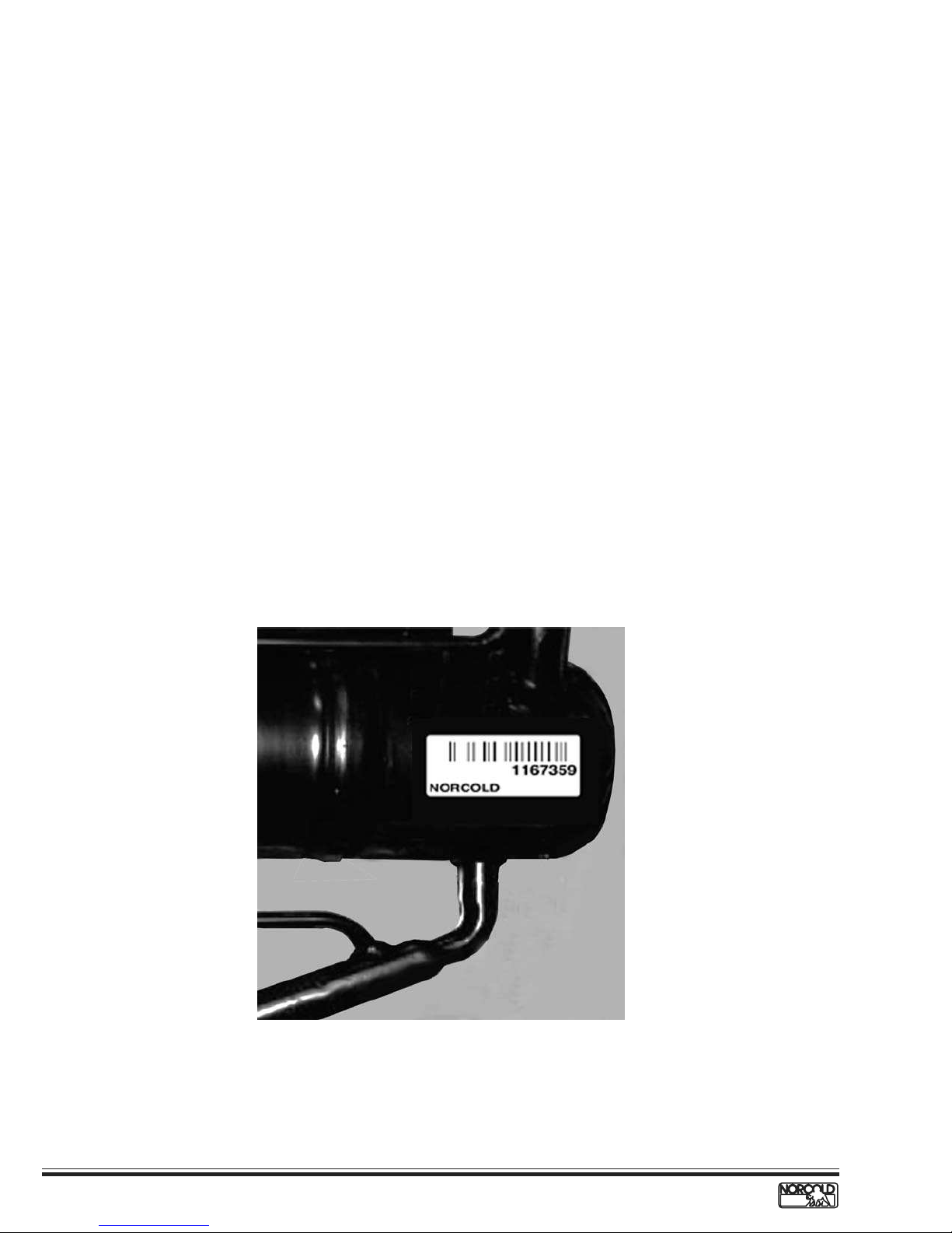
Figure 1. Refrigerator Information Label Location.
Figure 2. Cooling Unit Bar Code Label Location.
2
www.norcold.com/cda
Refrigerator Service ManualN6XX/N8XX Models
Safety Notice
It is not possible to anticipate all of the conceivable
ways or conditions under which the refrigerator may be
serviced or to provide cautions as to all of the possible
hazards that may result. Standard and accepted safety
precautions and equipment should be used when
working on electrical circuits and handling toxic or
flammable materials. Safety goggles and other
required protection should be used during any process
that can cause material removal, such as when
removing a leaking cooling unit and cleaning
components.
Attention Statements
The safety alert symbol followed by the word
WARNING or CAUTION identifies potential safety
hazards or conditions.
Safety Statements
Do not modify, alter, or equip the refrigerator to the
use of any other fuel (natural gas, butane, etc.). N6XX/
N8XX refrigerators are designed and equipped for the
use of LP gas–propane gas–only.
Incorrect installation, adjustment, alteration, or
maintenance of the refrigerator can cause personal
injury, property damage, or both.
SAFETY AWARENESS
The safety alert symbol with the appropriate heading
appear on all safety labels posted on the refrigerator
and safety awareness notices presented throughout
this manual.
WARNING:
The above heading identifies hazards or conditions,
which if ignored can cause serious injury, death, and/
or extensive property damage.
CAUTION:
The above heading identifies hazards, which if ignored
can cause injury and/or property damage.
Do not use leak test solutions that contain ammonia
or chlorine. Ammonia and chlorine degrade copper and
brass components.
The cooling unit is a sealed system under
pressure! Do not try to repair or recharge the cooling
unit. Do not bend, drop, weld, drill, puncture, saw, or
strike the cooling unit.
Do not smoke, light fires, or create sparks when
working on the propane gas system.
Do not use an open flame for leak testing any of the
propane gas system components. Propane gas is
highly flammable and explosive.
Always use two wrenches to tighten or loosen LP gas
connections. Damaged connections, piping, and
components create the potential for gas leaks.
All electrical connections and repairs to the
refrigerator must comply with all applicable codes.
Refer to the certification and code requirements
section of the N6XX/N8XX Installation Manual.
Do not work on live electrical circuits. Turn off AC
power and DC power sources before attempting to
remove, service, or repair any of the refrigerator's
electrical or electronic components.
Do not modify, bypass, or eliminate any of the
refrigerator's electrical components, electronic circuits,
or propane gas system components.
Do not wet or spray liquids on or near electrical
connections or electronic components. Most liquids,
including leak detection solutions, are electrically
conductive and pose the potential for an electric shock
hazard, short electrical components, damage
electronic circuits, and/or ignite a fire.
Handle a leaking cooling unit with extreme
caution! The cooling unit contains ammonia,
hydrogen, and sodium chromate. Ammonia can cause
severe skin and eye burns. Hydrogen is highly
flammable, can ignite and burns with an intense flame.
Certain chromium compounds, such as sodium
chromate, are carcinogenic.
Do not use extension cords. Do not remove the
grounding prong from the refrigerator AC power cord.
Do not use a two prong adapter to connect the
refrigerator to the AC outlet.
Do not over-fuse electrical circuits. Use specified
fuses and AWG wire sizes. The specification section
of this manual provides fuse size information. Refer to
the N6XX/8XX Installation Manual for the correct AWG
wire size specifications.
Prevent child entrapment! Before disposing of the
refrigerator, remove all doors and fasten all shelves
with retainers.
Some of the refrigerator's metal components have
sharp corners and edges. Wear hand protection, such
as cut resistant gloves, and exercise extreme care
when handling the refrigerator.
Make sure all hardware such as hinges and fasteners
(retaining screws, etc.), are properly fastened.
www.norcold.com/cda 3N6XX/N8XX ModelsRefrigerator Service Manual
SPECIFICATIONS
N61X/N81X Models
Storage volume
N61X --------------------------------------------------------------------------------------------------------------------------------- 6.3 ft3.
N81X --------------------------------------------------------------------------------------------------------------------------------- 7.5 ft
Rough opening dimensions (H x W x D)
N61X ------------------------------------------------------------------------------------------------------ 52
N81X ----------------------------------------------------------------------------------------------------- 59
7
/8
in. x 23
7
/8
in. x 23
1/2
in. x 24 in.
1/2
in. x 24 in.
3
.
Decorative panels dimensions
3/16
Thickness --------------------------------------------------------------------------------------------------------------------------Freezer door (H x W, both models) ---------------------------------------------------------------------14
17/32
in. x 21
19/32
in.
in.
Fresh food compartment (H x W)
N61X ------------------------------------------------------------------------------------------------------------- 31
N81X ------------------------------------------------------------------------------------------------------------- 38
5/8
in. x 21
5/8
in. x 21
19/32
19/32
in.
in.
Controls
Type ---------------------------------------------------------------------------------------------- Electronic with built-in diagnostics
Mode selector switch ------------------------------------------------------------------------------------------ 3-position slide type
Temperature switch --------------------------------------------------------------------------------------------- 5-position slide type
Temperature settings ---------------------------------------------------------------------------------------------- 1=cold, 5=coldest
Temperature sensor ----------------------------------------------------------------------------- Thermistor, fin mounted (10th fin)
Off-level operating limits
Side-to-side------------------------------------------------------------------------------------------------------- 3 degrees-maximum
Front-to-back ----------------------------------------------------------------------------------------------------- 6 degrees-maximum
DC power
Controls operating voltage ----------------------------------------------------------------------------------------- 10.5 to 15.4 Vdc
Fuse, control circuit (F1 in power board) -------------------------------------------- 5 A (tan color), automotive blade type
Fuse, fan (N6XXF/N8XX F models with an in-line fuse) --------------------- 1 A,
1
/4
in. x 1
1
in. AGC type fast acting
/4
DC amperage draws (at nominal 12 Vdc)
Automatic ignition ----------------------------------------------------------------------------------------------------------------- 0.50 A
Divider heater ---------------------------------------------------------------------------------------------------------------------- 0.25 A
Fresh food compartment lamp ------------------------------------------------------------------------------------------------- 0.46 A
Gas valve --------------------------------------------------------------------------------------------------------------------------- 0.146 A
Fan (N6XX/FN8XXF models only) ---------------------------------------------------------------------------------------------- 0.36 A
AC power
AC heater operating voltage ----------------------------------------------------------------------------------------- 108 to 132 Vac
Fuse, AC heater circuit (F3 in power board) ---------------------------------- 5 A,
AC heater rating ------------------------------------------------------------------ 300 W/2.5 A @ 120 Vac (resistance of 48Ω)
LP gas (propane)
Operating pressure ---------------------------------------------------------------------------------------------- 10.5 to 11.5 in. w.c.
Heat output --------------------------------------------------------------------------------------------------1500 Btu/h @ 11 in. w.c.
Orifice ---------------------------------------------------------------------------------------------------------------------------------- LP16
Gas ignition---------------------------------------------------------------------------------- Automatic with flame sensing circuit
Electrode tip-to-burner air gap ---------------------------------------------------------------------------------------- 1/8 to 3/16 in.
4
www.norcold.com/cda
Refrigerator Service ManualN6XX/N8XX Models
1
/4
in. x 1
1
in. AGC type fast acting
/4
N62X/N82X Models
Storage volume
N62X --------------------------------------------------------------------------------------------------------------------------------- 6.3 ft3.
N82X --------------------------------------------------------------------------------------------------------------------------------- 7.5 ft
Rough opening dimensions (H x W x D)
N62X ------------------------------------------------------------------------------------------------------ 52
N82X ------------------------------------------------------------------------------------------------------ 59
7
/8 in. x 231/2 in. x 24 in.
7
/8 in. x 23
1
/2 in. x 24 in.
3
.
Decorative panels dimensions
Thickness --------------------------------------------------------------------------------------------------------------------------Freezer door (H x W, both models) ---------------------------------------------------------------------14
17/32
in. x 21
3
/16 in.
19/32
in.
Fresh food compartment door
N62X -------------------------------------------------------------------------------------------------------------- 31
N82X -------------------------------------------------------------------------------------------------------------- 38
5
/8 in. x 21
5
/8 in. x 2119/32 in.
19
/32 in.
Controls
Type --------------------------------------------------------------------------------------- Electronic with built-in diagnostic mode
ON/OFF/MODE/TEMP SET switches ------------------------------------------------------------------------ Flush push-button
Temperature settings ---------------------------------------------------------------------------------------------- 1=cold, 9=coldest
Temperature sensor ----------------------------------------------------------------------------- Thermistor, fin mounted (10th fin)
Off-level operating limits
Side-to-side ------------------------------------------------------------------------------------------------------- 3 degrees-maximum
Front-to-back ----------------------------------------------------------------------------------------------------- 6 degrees-maximum
DC power
Controls operating voltage ----------------------------------------------------------------------------------------- 10.5 to 15.4 Vdc
Fuse, control circuit (F1 in power board) -------------------------------------------- 5 A (tan color), automotive blade type
Fuse, fan (N6XXF/N8XX F models with in-line fuse) ------------------------- 1 A,
1
/4
in. x 1
1
in. AGC type fast acting
/4
DC amperage draws (at nominal 12 Vdc)
Automatic ignition ----------------------------------------------------------------------------------------------------------------- 0.50 A
Divider heater ---------------------------------------------------------------------------------------------------------------------- 0.25 A
Fresh food compartment lamp ------------------------------------------------------------------------------------------------- 0.46 A
Gas valve --------------------------------------------------------------------------------------------------------------------------- 0.146 A
Fan (N6XX/FN8XXF models only) ---------------------------------------------------------------------------------------------- 0.36 A
AC power
AC heater operating voltage ----------------------------------------------------------------------------------------- 108 to 132 Vac
Fuse AC heater circuit (F3 in power board) ----------------------------------- 5 A,
AC heater rating
Refrigerators with serial number lower than 854647 ----------------- 300 W/2.7 A @ 110 Vac (resistance of 41.25 Ω)
Refrigerators with serial number 854647 and higher --------- 300 W/2.5 A/48 Ω @ 120 Vac (resistance of 41.25 Ω)
LP gas (propane)
Operating pressure ---------------------------------------------------------------------------------------------- 10.5 to 11.5 in. w.c.
Heat input ---------------------------------------------------------------------------------------------------- 1500 Btu/h @ 11 in. w.c.
Orifice, new style -------------------------------------------------------------------------------------------------------------------- LP16
Orifice, old style ---------------------------------------------------------------------------------------------------------- 0.155 jeweled
Gas ignition---------------------------------------------------------------------------------- Automatic with flame sensing circuit
Electrode tip-to-burner air gap --------------------------------------------------------------------------------------- 1/8 to 3/16 in.
1
/4
www.norcold.com/cda 5N6XX/N8XX ModelsRefrigerator Service Manual
in. x 1
1
in. AGC type fast acting
/4
N64X/N64X.3/N84X/N84X.3 Models
Storage volume
N64X/N64X.3 ----------------------------------------------------------------------------------------------------------------------- 6.3 ft
N84X/N84X.3 ----------------------------------------------------------------------------------------------------------------------- 7.5 ft
Rough opening dimensions (H x W x D)
N64X/N64X.3 -------------------------------------------------------------------------------------------- 52
N84X/N84X.3 -------------------------------------------------------------------------------------------- 59
7
/8 in. x 231/2 in. x 24 in.
7
/8 in. x 23
1
/2 in. x 24 in.
Decorative panels dimensions
Thickness --------------------------------------------------------------------------------------------------------------------------Freezer door (H x W, both models) --------------------------------------------------------------------- 14
17
/32 in. x 21
3
19
/16 in.
/32 in.
Fresh food compartment door
N64X/N64X.3 ---------------------------------------------------------------------------------------------------- 31
N84X/N84X.3 ---------------------------------------------------------------------------------------------------- 38
5
/8 in. x 21
5
/8 in. x 21
19
19
/32 in.
/32 in.
Controls
Type ------------------------------------------------------------------------------------ Electronic with built-in diagnostic function
ON/OFF/MODE/TEMP SET switches ---------------------------------------------------------------------- Raised push-button
Temperature settings ---------------------------------------------------------------------------------------------- 1=cold, 9=coldest
Temperature sensor ----------------------------------------------------------------------------- Thermistor, fin mounted (10
th
fin)
Off-level operating limits
Side-to-side------------------------------------------------------------------------------------------------------- 3 degrees-maximum
Front-to-back ----------------------------------------------------------------------------------------------------- 6 degrees-maximum
DC power
Controls operating voltage ----------------------------------------------------------------------------------------- 10.5 to 15.4 Vdc
DC fuse (F1 in power board) ------------------------------------------------------------ 5 A (tan color), automotive blade type
DC heater rating ----------------------------------------------------------------- 225 W/16 A @ 14 Vdc (resistance of 0.87 Ω)
DC heater operating voltage (3-way models only) ------------------------------------------------------------------ 12 – 14 Vdc
Fuse, DC heater (F2, in power board) ------------------------------------------- 30 A (green color), automotive blade type
Fuse, fan (N6XXFw/N8XX F models with in-line fuse holder) -------------- 1 A,
1
/4
in. x 1
1
in. AGC type fast acting
/4
3
.
3
.
DC amp draws (at nominal 12 Vdc)
Automatic ignition ----------------------------------------------------------------------------------------------------------------- 0.50 A
DC heater --------------------------------------------------------------------------------------- 13.79 A @ 12 Vdc/16 A @ 14 Vdc
Divider heater ---------------------------------------------------------------------------------------------------------------------- 0.25 A
Fresh food compartment lamp ------------------------------------------------------------------------------------------------- 0.46 A
Gas valve --------------------------------------------------------------------------------------------------------------------------- 0.146 A
Fan (N6XX/FN8XXF models only) ---------------------------------------------------------------------------------------------- 0.36 A
AC power
AC heater operating voltage requirements ----------------------------------------------------------------------- 108 to 132 Vac
Fuse AC heater circuit (F3 in power board) ------------------------------------ 5 A,
AC heater rating
Refrigerators with serial number lower than 854647 ----------------- 300 W/2.7 A @ 110 Vac (resistance of 41.25 Ω)
Refrigerators with serial number 854647 and higher -------------------- 300 W/2.5 A @ 120 Vac (resistance of 48 Ω)
LP gas (propane)
Operating pressure ----------------------------------------------------------------------------------------------- 10.5 to 11.5 in. w.c
Heat input -----------------------------------------------------------------------------------------------------1500 Btu/h @ 11 in. w.c
Orifice, new style -------------------------------------------------------------------------------------------------------------------- LP16
Orifice, old style ---------------------------------------------------------------------------------------------------------- 0.155 jeweled
Gas ignition---------------------------------------------------------------------------------- Automatic with flame sensing circuit
Electrode tip-to-burner air gap --------------------------------------------------------------------------------------- 1/8 to 3/16 in.
6
www.norcold.com/cda
1
/4
Refrigerator Service ManualN6XX/N8XX Models
in. x 1
1
in. AGC type fast acting
/4
TROUBLESHOOTING – QUICK REFERENCE GUIDE
Problem Possible Cause Checks/Reference
The refrigerator does not turn ON.
The refrigerator does not cool on
AC power.
The refrigerator does not cool
efficiently on AC power.
3-Way Units Only
The refrigerator does not cool on
DC power.
3-Way Units Only
The refrigerator does not cool
efficiently on DC power.
No 12 Vdc power to refrigerator.
Faulty/loose 12 Vdc connections.
F1 fuse in power board open.
No AC power to refrigerator.
F3 fuse in the power board open.
AC heater failed open.
Ventilation obstructed.
AC voltage low.
F2 fuse in power board open.
DC heater failed open.
Ventilation obstructed.
DC voltage below 12 volts.
See page 11.
Check 12 Vdc connections.
Check fuse F1, (5 amp) in power board.
See page 16.
Check fuse F3, (5 amp) in power board.
See page 18.
Check enclosure for air flow obstructions.
See page 17.
Check fuse F2 (30 amp) in power board.
See page 15.
Check enclosure for obstructed air flow.
Check RV 12 Vdc power supply.
The refrigerator does not operate
on LP gas.
The refrigerator does not
cool efficiently on LP gas.
"no" "co" code.
No LP gas.
Incorrect electrode tip-to-burner gap.
Faulty spark/sense electrode assembly.
Flame sensing circuit failure.
Ventilation obstructed.
Incorrect LP gas pressure.
Dirty burner.
Missing flue baffle.
Heat deflector blocked.
Poor ventilation.
Off-level operation.
DIrty burner.
Low AC voltage.
Cooling fan inoperative.
Improper installation.
Incorrect orifice.
Check LP gas supply and valves.
See page 12.
See page 12.
See page 13.
Check enclosure for obstructed air flow.
See page 12.
See page 12.
See page 30.
See page 30.
Check enclosure for obstructed air flow.
See page 37.
See page 31.
See page 34.
See page 35.
See pages 22-26.
See page 29.
www.norcold.com/cda 7N6XX/N8XX ModelsRefrigerator Service Manual
N61X/N81X DISPLAYED FAULT CODES
Problem
ON LED off.
ON LED and GAS LED flashing at one second
intervals.
ON LED on.
GAS LED flashes at one second intervals.
ON LED flashes once every three seconds.
Probable Cause
Refrigerator turned off.
No 12 Vdc to refrigerator.
F1 fuse open.
In AUTO operation:
No AC power or LP gas available
GAS operation:
Burner failed to ignite or reignite.
"Gas lock-out."
Burner failed to ignite or reignite.
Back-up system operation.
Reference
See page 11.
See page 16.
See page 12.
See page 12.
See page 20.
ON LED flashes twice every three seconds.
ON LED flashes three times every three
seconds.
ON LED flashes four times every three seconds.
ON LED flashes five times every three seconds.
Mode switch failure. Refrigerator
operating in last selected mode.
AC heater failure.
Controls failure.
No cooling detected by the controls.
Replace optical
control assembly.
See page 18.
Replace
power board.
See pages
21 & 37.
8
www.norcold.com/cda
Refrigerator Service ManualN6XX/N8XX Models
N62X/N82X DISPLAYED FAULT CODES
Blank
Display
Screen
Probable Cause
Refrigerator turned off.
No 12 Vdc to refrigerator.
F1 fuse open.
Burner failed to ignite or reignite.
Flame sense circuit failure.
DC voltage low.
DC voltage high.
ReferenceCode
See page 11.
See page 12.
See page 13.
See page 13.
See page 14.
Flashing
Tem p
Setting
AC relay stuck closed.
No AC power available to refrigerator.
AC cord not plugged into power board.
F3 fuse open.
AC heater failed open.
Fresh food compartment door open more then 2 minutes.
Lamp reed relay switch faulty.
Back-up operating system.
No cooling detected by the controls.
See page 16.
See page 16.
See page 18.
See page 19.
See page 20.
See pages
21 & 37.
www.norcold.com/cda 9N6XX/N8XX ModelsRefrigerator Service Manual
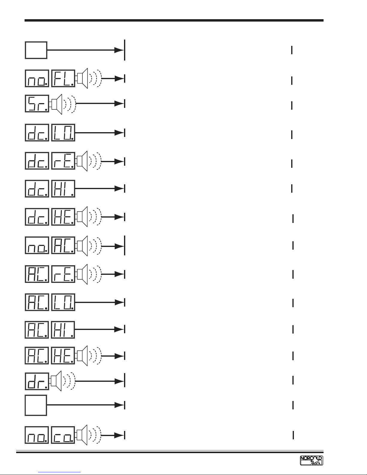
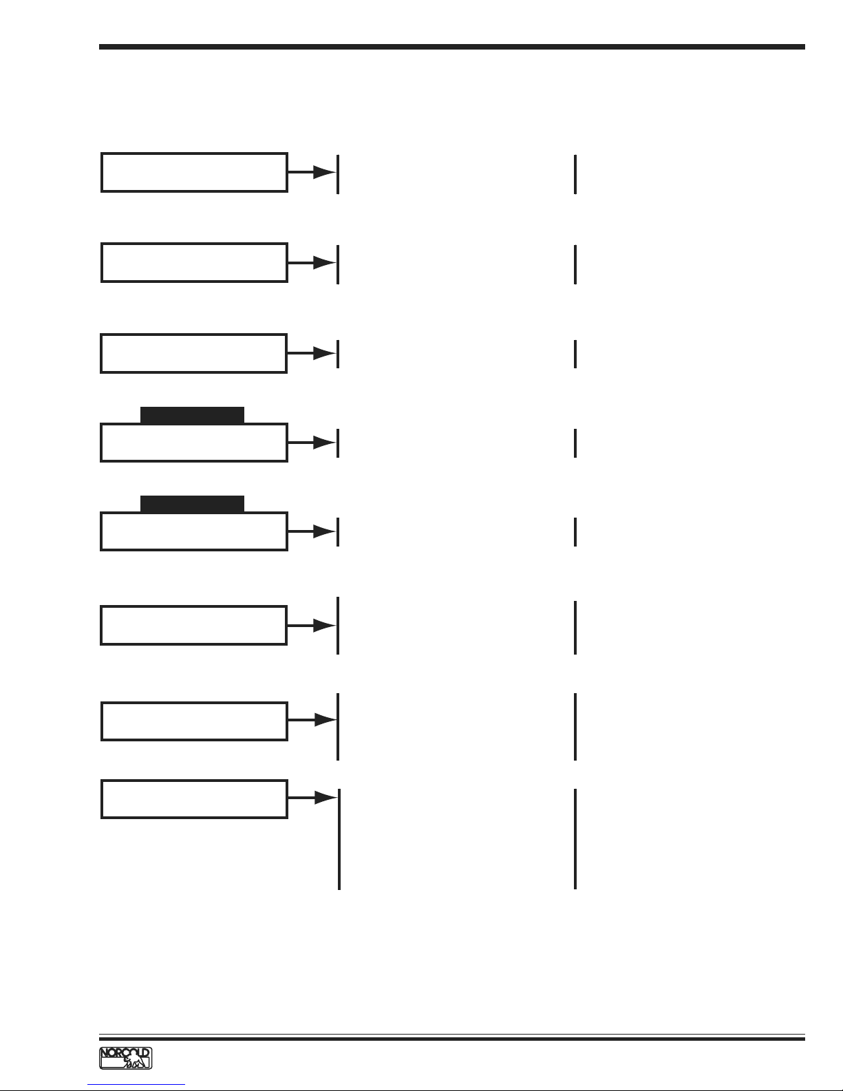
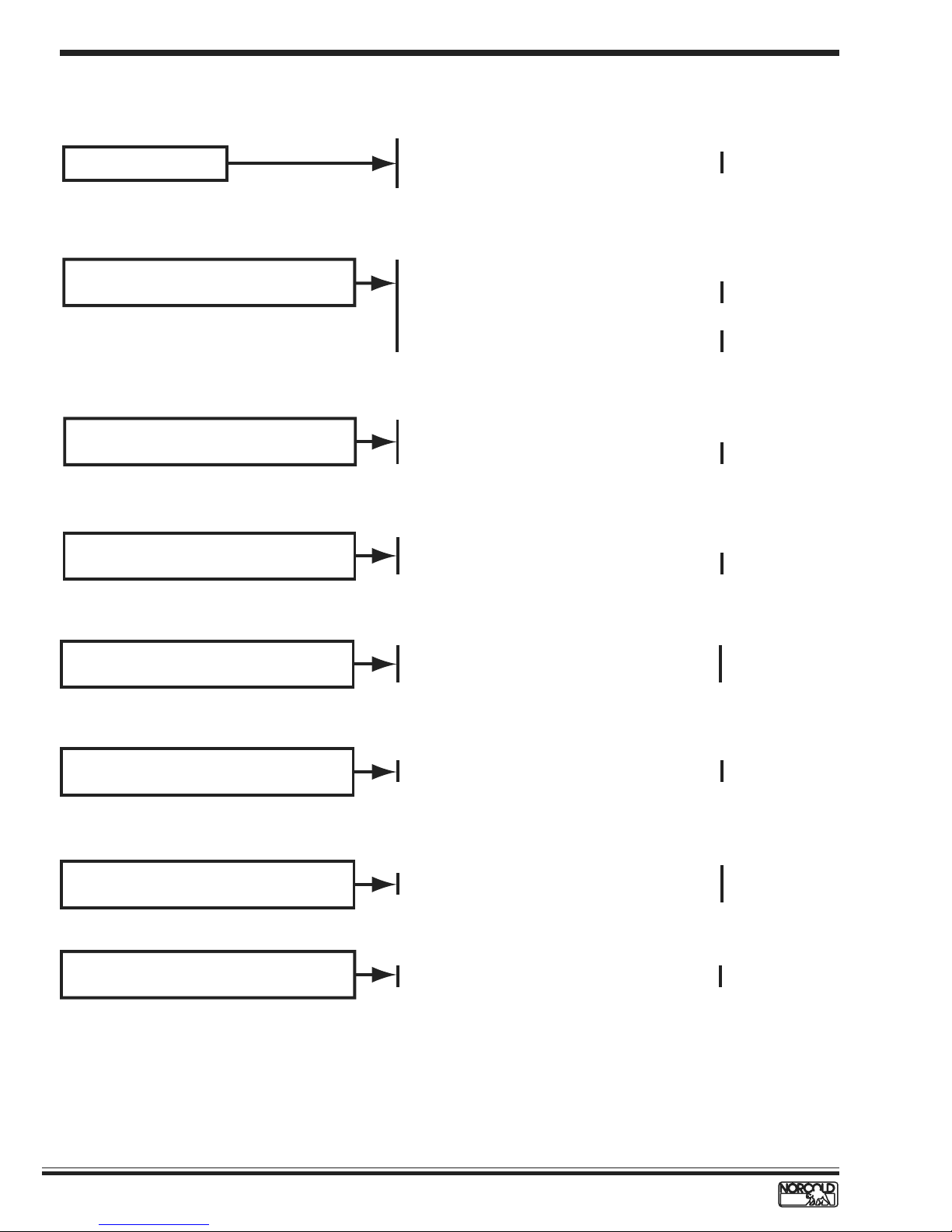
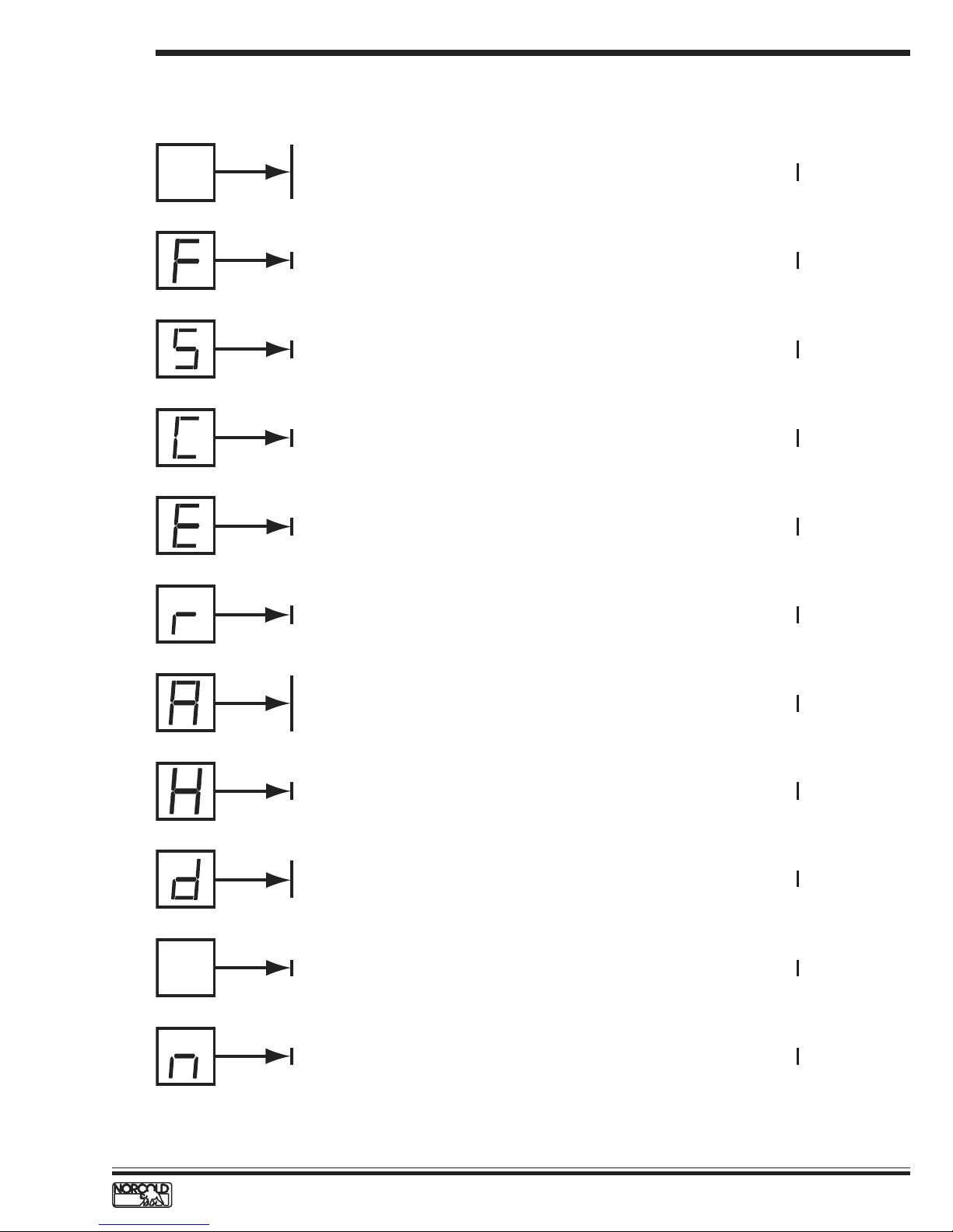
N64X/N84X DISPLAYED FAULT CODES
Code
Blank
Display
Screen
Probable Cause
Reference
Refrigerator turned off.
No 12 Vdc to refrigerator.
See page 11.
F1 fuse open.
a
t
i
n
n
r
g
e
t
l
A
y
D
a
l
i
s
p
Audible
Alarm
n
a
r
t
e
i
n
t
l
g
A
D
y
i
a
l
s
p
a
n
t
r
i
n
e
t
g
l
A
D
y
a
i
l
s
p
a
n
t
r
i
n
e
t
g
l
A
D
y
i
a
l
s
p
a
n
t
r
i
n
e
t
g
l
A
D
y
i
s
a
l
p
a
n
t
r
i
n
e
t
g
l
A
D
y
i
a
l
s
p
a
n
t
r
i
n
e
t
g
l
A
y
D
a
l
i
s
p
a
n
t
r
i
n
e
t
l
g
A
Audible
Alarm
Audible
Alarm
Audible
Alarm
Audible
Alarm
Audible
Alarm
The burner failed to ignite or reignite.
Flame sense circuit failure.
DC voltage low.
DC relay stuck closed, 3-way models only.
DC voltage high.
DC heater failure, 3-way models only.
No AC power available to refrigerator.
AC cord not plugged into power board.
F3 fuse open.
AC relay stuck closed.
See page 12.
See page 13.
See page 13.
See page 14.
See page 14.
See page 15.
See page 16.
See page 16.
D
y
i
a
l
s
p
a
t
i
n
n
r
g
e
t
l
A
D
y
i
a
l
s
p
a
t
i
n
n
r
g
e
t
l
A
D
y
i
a
l
s
p
Audible
Alarm
Audible
Alarm
Flashing
Tem p
Setting
a
t
n
i
r
n
e
g
t
l
A
D
y
i
a
l
s
p
Audible
Alarm
10
AC voltage low.
AC voltage high.
AC heater failed open.
Fresh food compartment door open more than 2 minutes.
Lamp reed relay switch faulty.
Back-up operating system.
No cooling detected by the controls.
www.norcold.com/cda
Refrigerator Service ManualN6XX/N8XX Models
See page 17.
See page 17.
See page 18.
See page 19.
See page 20.
See pages
21 & 37.
TROUBLESHOOTING FLOWCHARTS
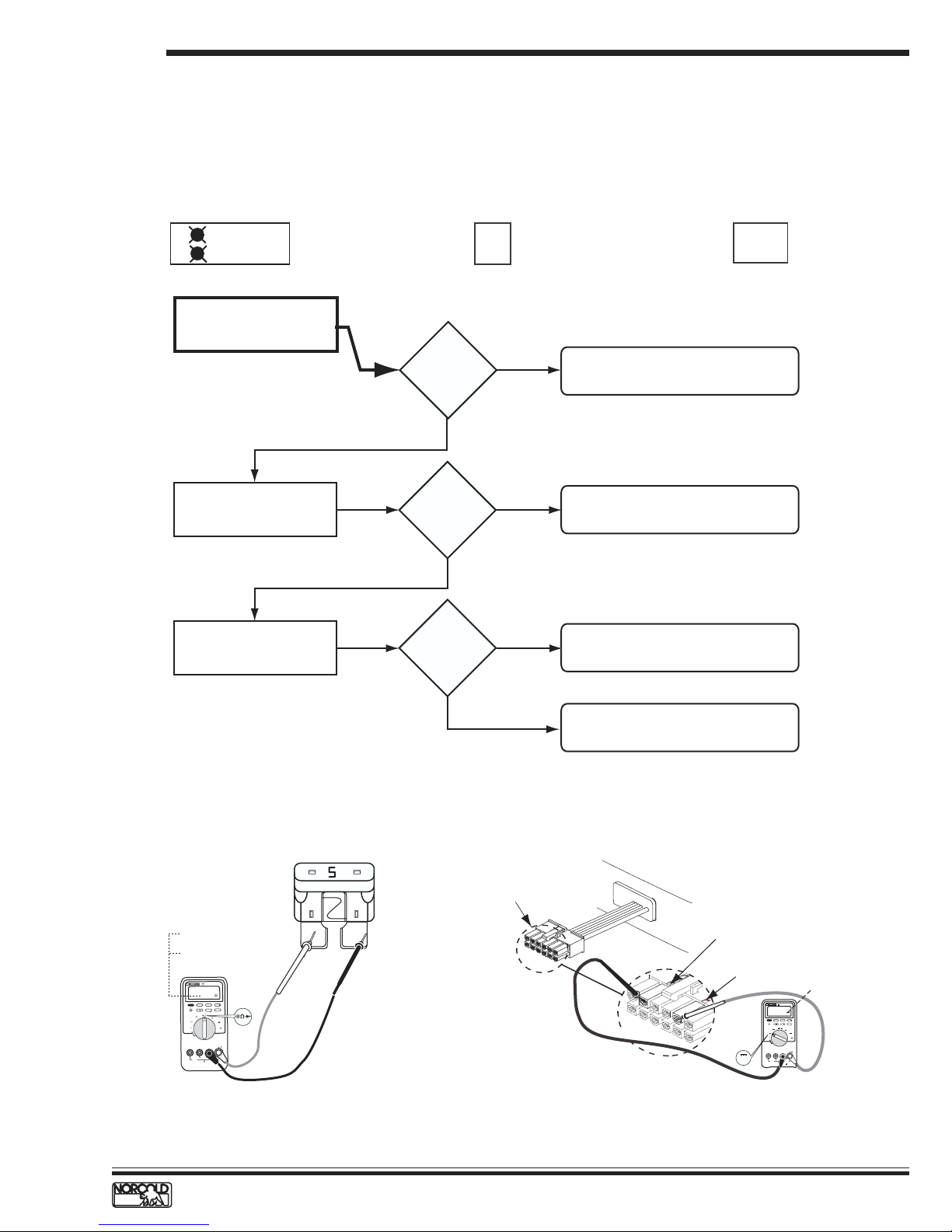
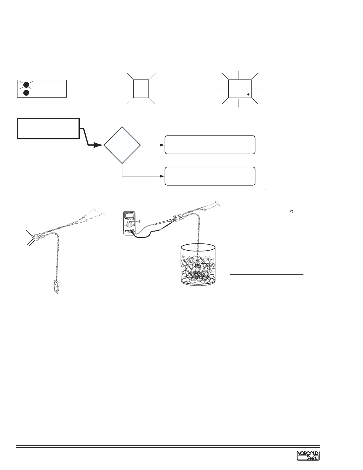
Blank Display – Refrigerator does not turn on
Before beginning this procedure make sure:
The RV DC power system is supplying 10.5 to 15.4 volts to the refrigerator.
No other RV appliances or lighting circuits are connected to the refrigerator DC circuit.
12 Vdc input to the power board is wired according to the N6XX/N8XX installation manual.
Models and fault indicator displayed.
ON
GAS
check if flashing
N61X/N81X
Measure voltage at power
board 12VDC and GND1
connections.
Check condition of F1 fuse
in power board. See Figure A.
Measure voltage at optical
control harness.
See Figure B.
AUTO
N62X/N82X
10.5
to
15.4 Vdc?
YES
F1 fuse okay?
YES
Voltage
present?
Blank
Display
Screen
LP GASAC
NO
NO
NO
Blank
Display
Screen
N64X/N84X
1. No DC power input from RV to unit.
2. Faulty wiring or connectors.
Replace fuse. Use a standard 5 amp
(tan color) automotive blade type fuse.
Replace power board.
Good= 00.0
Ω
Bad = OL
R
METE
TRUE RMS MULTI
87
III
00.0
H
HOLD
GE
RAN
AX
IN M
M
Hz
REL
X
MA
N
MI
AK
PE
GITS
I
D
4 1/2
Seconds
1
mV
mA
A
V
A
µ
V
OFF
V
COM
A
µ
mA
A
!
400mA MAX
T II
CA
FUSED
MAX
1000V
X
MA
10A
FUSED
!
Checking DC fuse continuity.
Figure A.
YES
Replace optical control board.
Wire harness optical
control display connector
White/violet wire
White/red wire
10.5 to 15.4 Vdc
TRUE RMS MULTI METER
87
III
V
H
MIN MAX RANGE HOLD
HzREL
PEAK MIN MAX
4 1/2 DIGITS
1 Seconds
mV
mA
V
A
µA
V
OFF
V
COM
A
mA µA
!
400mA MAX
CAT II
FUSED
1000V MAX
10A MAX
V
!
FUSED
Optical control display wire harness connection voltage measuring points.
Figure B.
www.norcold.com/cda 11N6XX/N8XX ModelsRefrigerator Service Manual
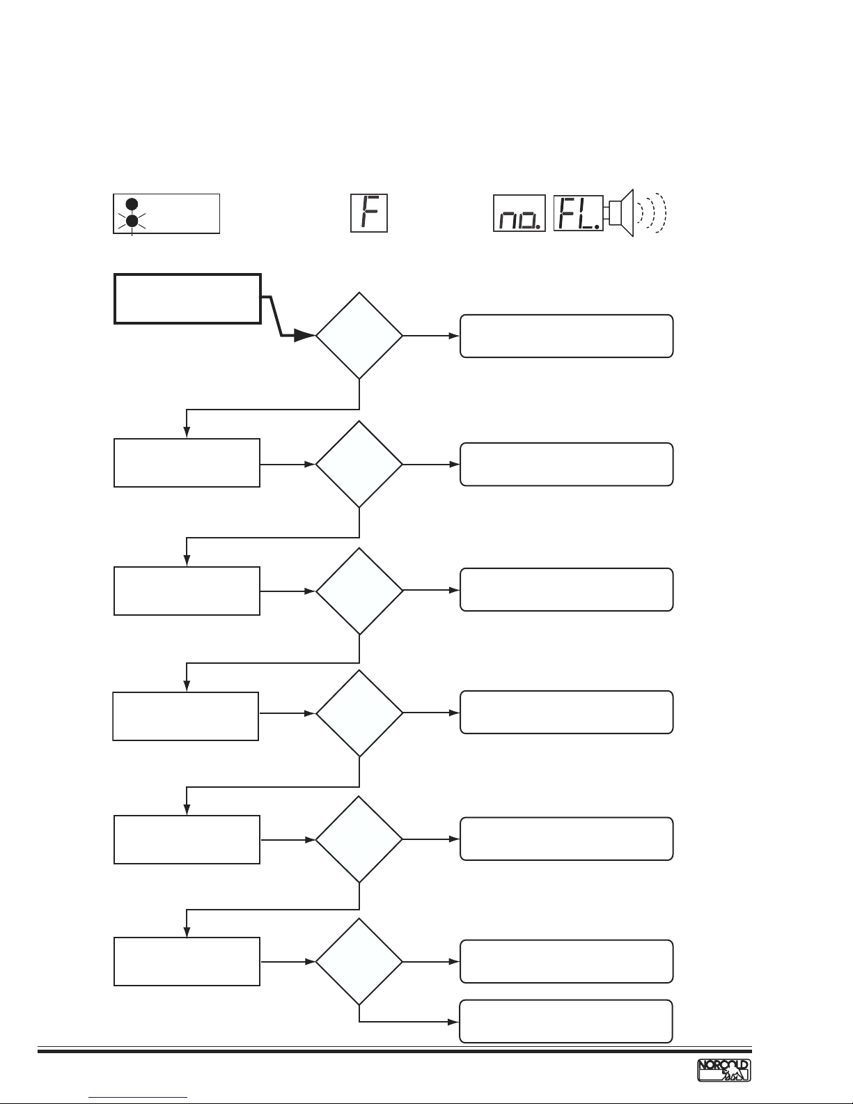
F/no FL Fault Code – Burner failed to ignite or reignite
Before beginning this procedure make sure:
RV LP gas tank valve is open.
Refrigerator solenoid gas valve manual shutoff is open.
LP gas pressure at the solenoid gas valve pressure tap is 10.5.
Models and fault indicator displayed.
ON
GAS
N61X/N81X
Check burner.
GAS LED
flashing
constantly
AUTO
N62X/N82X
LP GASAC
a
n
t
r
e
t
l
A
D
i
a
s
l
p
N64X/N84X
i
n
g
y
Audible
Alarm
Check that electrode tip-toburner air gap is correct.
Check spark/sense electrode
assembly for continuity.
Check gas valve solenoid
resistance.
.
Burner
clean?
YES
Air gap
1/8 to 3/16
inch?
YES
Continuity?
YES
79 to 85 Ω?
NO
NO
NO
NO
Clean and service burner.
See page 30.
Set electrode-to-burner air gap
1/8 to 3/16 inch.
Replace spark/sense electrode
assembly.
Replace gas valve.
Check gas valve solenoid
wires for continuity.
Check voltage across power
board terminals GV and
GV GND.
12
YES
Continuity?
NO
YES
Voltage?
NO
YES
www.norcold.com/cda
Replace gas valve wires.
Replace power board.
Faulty or obstructed gas valve.
Replace gas valve.
Refrigerator Service ManualN6XX/N8XX Models
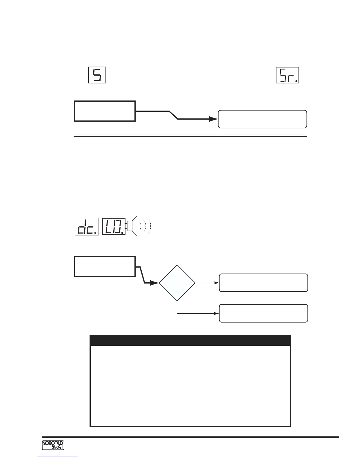
S/Sr Fault Code – Flame sense circuit failure
Models and fault indicator displayed.
LP GASAC
AUTO
N62X/N82X N64X/N84X
Flame sense circuit failure.
Replace power board.
See page 44.
dc LO Fault Code – Low DC voltage
Before beginning this procedure:
Make sure RV DC voltage to refrigerator is 10.5 to 15.4 volts.
Determine if the DC LO fault code displays when the converter is the source of DC power.
Make sure no other appliance or lighting circuit is connected to the refrigerator DC circuit.
Models and fault indicator displayed.
a
n
t
r
i
e
t
l
A
D
i
N64X/N84X
Check for DC voltage input
to power board terminals
12VDC and GND1.
n
g
y
a
s
l
p
Audible
Alarm
Voltage
lower than
10.5 Vdc?
YES
Check RV 12 Vdc power supply to
refrigerator.
Electronic controls operate on 12 Vdc. When an AC/DC converter is used to
supply DC power, the refrigerator circuit must be connected to the appliance
output terminals of the converter (filtered side).
If the refrigerator circuit is connected to the unfiltered side, the AC ripple
generated by the converter may cause a dc LO fault code to display.
To troubleshoot a dc LO fault, connect a charged 12 volt automotive battery
to the power board. If the dc LO code clears, the fault was caused by unfiltered
DC power.
If the dc LO code does not clear, replace the power board.
NO
See NOTE below to determine
and correct low dc LO fault.
NOTE
www.norcold.com/cda 13N6XX/N8XX ModelsRefrigerator Service Manual
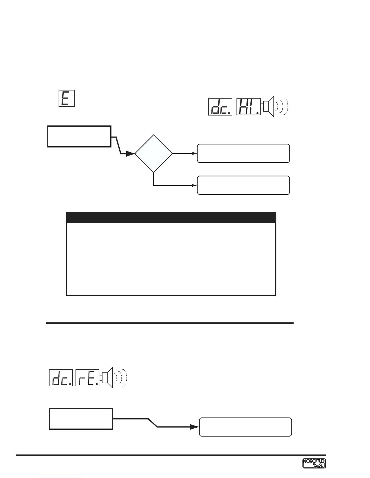
dc HI Fault Code – DC voltage high
Before beginning this procedure:
Make sure RV DC voltage to refrigerator is 10.5 to 15.4 volts.
Determine if the DC HI fault code displays when the converter is the source of DC power.
Models and fault indicator displayed.
a
n
t
r
i
n
g
AUTO
e
LP GASAC
A
t
l
Audib
le
N62X/N82X
Check for DC voltage input
to power board terminals
12VDC and GND1.
Electronic controls operate on 12 Vdc. When an AC/DC converter is used to
supply DC power, the refrigerator circuit must be connected to the appliance
output terminals of the converter (filtered side).
If the refrigerator circuit is connected to the unfiltered side, the AC ripple
generated by the converter may cause a dc HI fault code to display.
To troubleshoot a dc HI fault, connect a charged 12 volt automotive battery to
the power board. If the dc HI code clears, the fault was caused by unfiltered
DC power. If the dc HI code does not clear, replace the power board.
Voltage
higher than
15.4 Vdc?
NOTE
YES
NO
D
y
i
a
s
l
p
N64X/N84X
Check RV DC power distribution to
refrigerator.
See NOTE below to determine
and correct low dc HI fault.
Alarm
dc rE Fault Code – DC relay stuck closed
Models and fault indicator displayed
a
n
t
r
i
n
e
t
g
l
A
D
y
i
a
l
s
p
Audib
Alarm
N64X/N84X
DC relay stuck closed.
14
le
www.norcold.com/cda
Replace power board.
See page 44.
Refrigerator Service ManualN6XX/N8XX Models
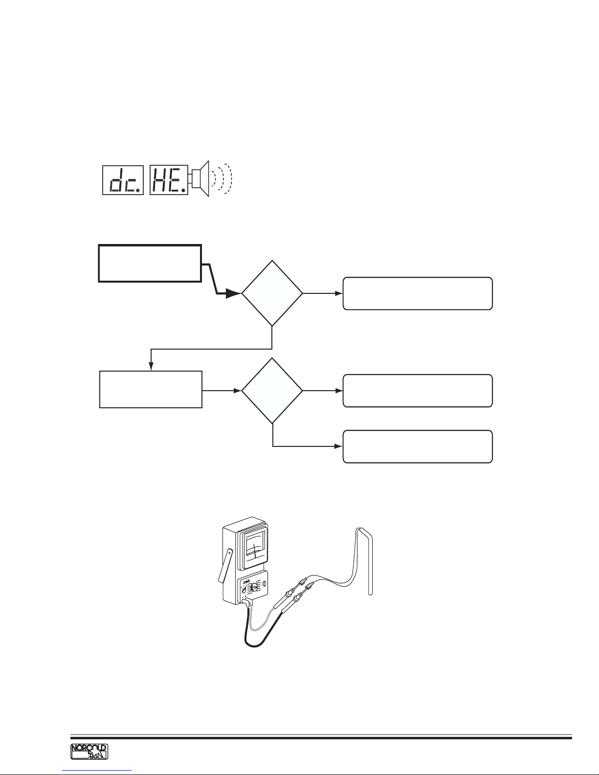
dc HE Fault Code – DC heater failed open
Before beginning this procedure make sure:
The RV DC electrical system is maintaining 10.5 to 15.4 Vdc to the refrigerator.
No other appliance or lighting circuit is connected to the refrigerator DC circuit.
Model and fault indicator displayed.
a
n
t
r
i
A
e
t
l
n
g
Audible
D
N64X.3/N84X.3
Check condition of F2 fuse
in power board.
Check DC heater resistance.
See Figure.
y
i
a
s
l
p
Alarm
F2 fuse
okay?
YES
Resistance
0.81 to 0.91
YES
NO
NO
Ω
?
Replace fuse. Use a standard 30 amp
(green color) automotive blade type fuse.
Replace DC heater.
Replace power board.
DC heater resistance 0.81 to 0.91
www.norcold.com/cda 15N6XX/N8XX ModelsRefrigerator Service Manual
Ω.Ω.
Ω.
Ω.Ω.
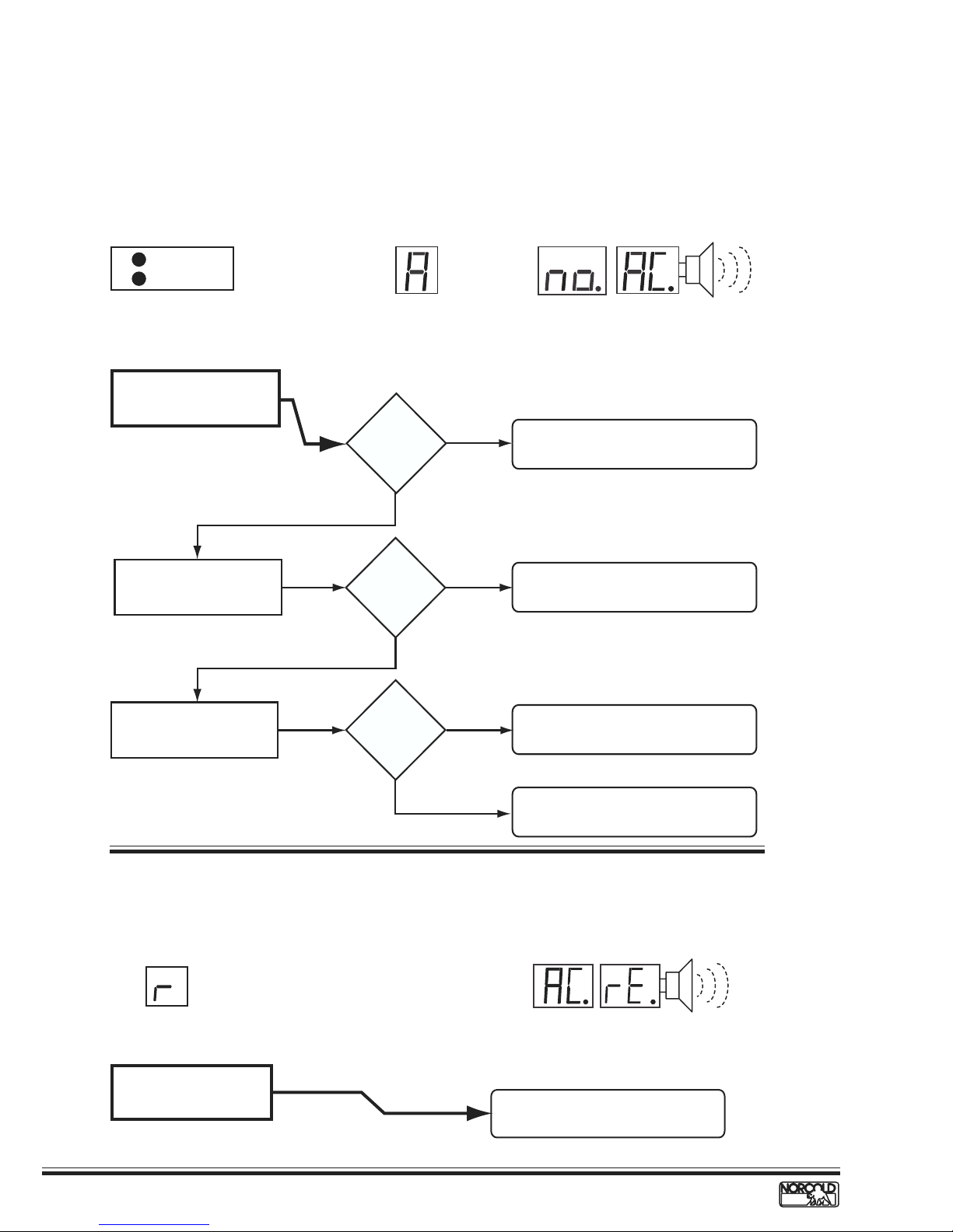
A/no AC Fault Code – No AC power available
Before beginning this procedure make sure:
No other problem exist with the RV AC power supply.
No other appliances or lighting circuits are connected to the refrigerator AC circuit.
Extension cords are not being used to supply AC power to the refrigerator.
Models and fault indicator displayed.
ON
GAS
check if flashing
Does not operate on AC when set to AUTO.
N61X/N81X
Measure voltage at power
board AC cord connection.
Check condition of F3 fuse
in power board.
AUTO
N62X/N82X
108
to
132 Vac?
YES
F3 fuse okay?
YES
a
n
t
r
i
A
e
t
l
n
g
Audib
e
l
LP GASAC
Alarm
NO
NO
D
y
i
a
s
l
p
N64X/N84X
1. Check AC power input from RV to unit.
2. Check for faulty AC power cord.
Replace fuse. Use a 5 amp, 1/4" x 11/4"
AGC type fuse.
Check that fuse holder clips
are making full contact with
fuse.
Clips okay?
YES
r/AC rE Fault Code – AC relay stuck closed
Models and fault indicator displayed.
LP GASAC
AUTO
N62X/N82X
Flame sense circuit failure.
NO
Adjust clips to ensure fuse contacts are
firm in clips and making full contact.
Replace power board.
a
n
t
r
i
n
e
t
g
l
A
D
y
i
a
l
s
p
Audib
Alarm
N64X/N84X
Replace power board.
See page 44.
le
16
www.norcold.com/cda
Refrigerator Service ManualN6XX/N8XX Models
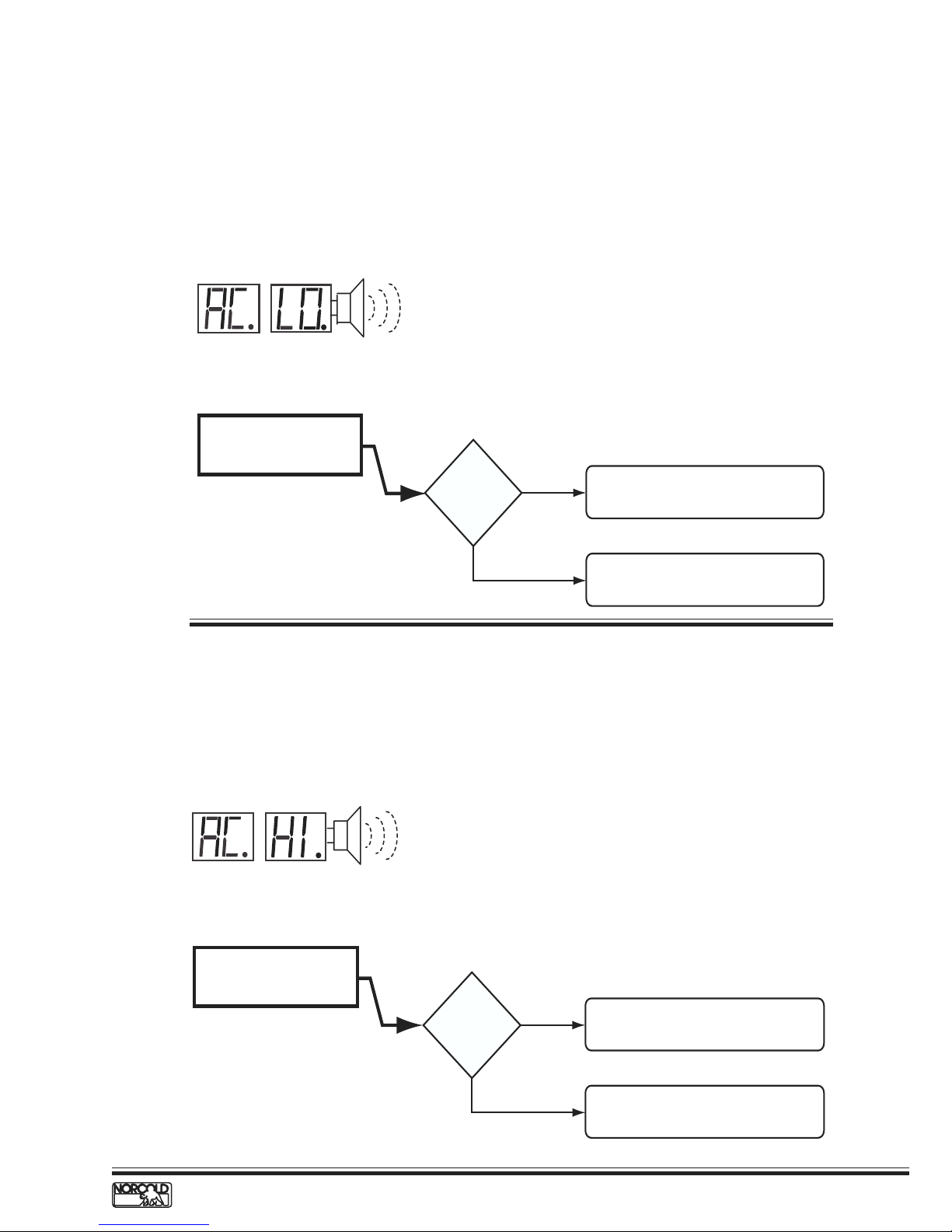
AC LO Fault Code – AC voltage low
Before beginning this procedure:
Determine if a certain AC power source sets the AC LO fault code (generator, shore power, inverter).
Make sure no other appliance or lighting circuit is connected to the refrigerator AC circuit.
Make sure extension cords are not being used to supply AC power to the refrigerator.
Model and indicator displayed.
a
n
t
r
i
A
e
t
l
n
g
le
Audib
D
N64X/N84X
Measure voltage at power
board AC cord connection.
y
i
a
s
l
p
Alarm
Voltage
lower than
108 Vac?
YES
NO
Fault related to RV AC power distribution
component or circuit supplying AC power
to refrigerator.
Replace power board.
AC HI Fault Code – AC voltage high
Before beginning this procedure:
Determine if a certain AC power source sets the AC HI fault code (generator, shore power, inverter).
Model and indicator displayed.
a
n
t
r
i
A
l
D
e
t
i
n
g
y
a
s
l
p
N64X/N84X
Measure voltage at power
board AC cord connection.
Audible
Alarm
Voltage
higher than
132 Vac?
www.norcold.com/cda 17N6XX/N8XX ModelsRefrigerator Service Manual
YES
NO
Fault related to RV AC power distribution
component or circuit supplying AC power
to refrigerator.
Replace power board.

H/AC HE Fault Code – AC heater failed open
Before beginning this procedure make sure:
RV AC voltage to the refrigerator is 108 to 132 volts.
No other appliance or lighting circuit is connected to the refrigerator AC circuit.
Models and indicator displayed.
a
n
t
r
i
e
t
l
A
ON
Flashin
g 3 tim
es e
very 3 seco
nds
GAS
N61X/N81X
Check AC heater wires for
loose or damaged connector.
AUTO
N62X/N82X
LP GASAC
Heater
connections
okay?
YES
N64X/N84X
NO
D
y
i
a
s
l
p
Repair or replace connectors. If
connectors cannot be repaired,
replace heater.
n
g
Audible
Alarm
Check AC heater resistance.
See See Figure.
Resistance
Ω
38 to 53
NO
?
YES
AC heater resistance 38 to 53
Replace AC heater.
Replace power board.
Ω.
18
www.norcold.com/cda
Refrigerator Service ManualN6XX/N8XX Models
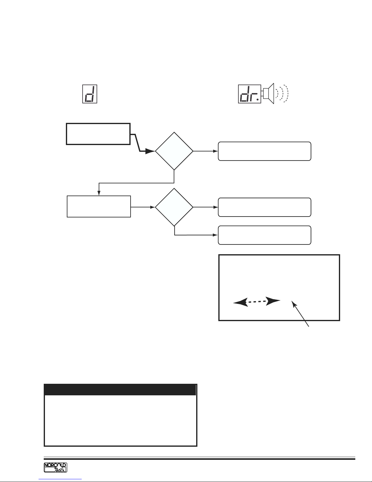
d/dr Fault Code – Door open for more than 2 minutes
Before beginning this procedure make sure:
Light/thermistor connector and wire harness connector are fully engaged and locked.
Models and fault indicator displayed.
LAP GASAC
AUTO
N62X/N82X
Check that the door latch
striker plate is adjusted
correctly.
Striker plate
okay?
YES
NO
N64X/N84X
Adjust striker plate.
Audib
Alarm
le
Check for correct door
installation. See NOTE below.
Was door
swing
changed?
YES
Food Compartment Lamp Switch
The reed relay switch that turns the fresh food
compartment light on and off is an integral component
of the optical control display board circuitry.
Lamp Switch Operation
The magnetic pull from a permanent magnet located
underneath the top door trim maintains the switch
contacts open (light off) when the door is fully closed.
Opening the door breaks the magnetic pull, which in
turn causes the switch contacts close (light on).
NOTE
Always follow the instructions provided in the Owner's
Manual to change the refrigerator door swing. The
bottom door trim does not have a magnet. Inverting
the doors will required non-approved modifications and
will cause the fresh food compartment light to remain
on when the door is closed.
NO
Test lamp switch operation. See switch
test procedure below.
Check for location of magnet if the door
swing was changed. See NOTE.
Move tip
Magnetic tip screwdriver
Lamp Switch Testing Procedure
1. Slide a magnetic screwdriver tip or a small magnet
on the underside of the optical control assembly
as shown in the figure above.
2. Check the food compartment light as the
screwdriver tip is moved under the display, the
light:
a. should turn off when the magnetic screwdriver tip
or magnet passes under the optical control
assembly.
b. turn on when the magnetic screwdriver tip or
magnet is distanced from the underside of the
optical control assembly.
3. If the light does not turn off when the magnet
passes under the optical control display, replace
the optical control display assembly.
www.norcold.com/cda 19N6XX/N8XX ModelsRefrigerator Service Manual
Thermistor Failure Fault – Controls in backup operating system mode
Before beginning this procedure:
Make sure lamp/thermistor assembly is connected to wire harness.
Models and fault indicator displayed.
ON
Flash
ing
once every 3 seconds
GAS
N61X/N81X
Check lamp/thermistor wire
assembly and connector for
dirty/broken connections.
Lamp
Connection
Thermistor
Connections
AUTO
Wires and
connector
good?
YES
Temp
Setting
Flashing
LP GASAC
Temp
Setting
Flashing
N64X/N84XN62X/N82X
NO
ER
MULTIMET
TRUE RMS
87
III
H
HOLD
NGE
MIN MAX RA
zR
H
EL
AX
M
PEAK MIN
1/2 DIGITS
4
1 Seconds
mV
mA
A
V
A
µ
V
FF
O
V
OM
C
A
mA µ
A
!
400mA MAX
AT II
C
FUSED
MAX
1000V
AX
10A M
FUSED
!
Clean/repair terminals or connector as
required. See Figure A.
Check thermistor resistance.
See Figure B and procedure below.
Temperature* Resistance*
(oF) (k )
85 8.1– 9.0
80 9.1–10.0
75 10.1–11.0
70 11.1– 12.0
60 12.1–13.0
50 15.5–16.5
40 22.5–23.5
35 24.5–25.5
33 28.5–29.5
32 30.0–32.0
*
Approximate Values
Thermistor
Figure A. Figure B.
Backup Operating System (BOS)
The backup operating system (BOS) is an
electronically controlled duty cycle that maintains the
refrigerator in operation if the thermistor is
disconnected or fails. The BOS maintains cooling by
timing the length of time the heat source is energized.
When the refrigerator is operating in BOS, the length
of the cooling cycle has to be regulated manually
using the TEMP switchbutton.
When a colder temperature is desired, changing the
temperature setting to a higher number provides
additional cooling by lengthening the cooling cycle.
For example, if the temperature setting is set to 5,
raising the setting to 6 will lengthen the cooling cycle.
20
Thermistor packed in ice bath
When a warmer temperature is desired, changing the
temperature setting to a lower number shortens the
cooling cycle. For example, if the temperature setting
is set to 6, lowering the setting to 5 will shorten the
cooling cycle.
N61X/N81X Backup Operation.
When the N61X/N81X controls shift to BOS operation,
the ON LED (green) flashes once every three seconds.
N62X/N82XN64X/N84X Backup Operation
When the N62X/N82XN64X/N84X controls shift to BOS
operation, the temperature setting flashes for ten
seconds when the TEMP button is pressed. After ten
seconds, the selected operation mode indicator
displays.
www.norcold.com/cda
Refrigerator Service ManualN6XX/N8XX Models
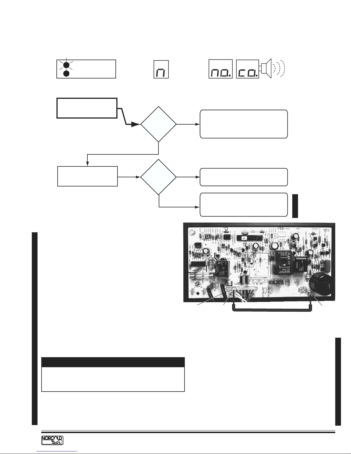
n/no co Fault Code – No cooling detected by the controls
Models and indicator displayed.
l
A
ON LED flashing
ON
5 times e
GAS
3 seconds
N61X/N81X
Check for cooling at fin
assembly.
very
AUTO
N62X/N82X
Cooling
detected?
YES
LP GASAC
D
N64X/N84X
1. Check for ventilation obstructions
NO
and leveled operation.
2. Reset power board as shown in
figure and described in procedure.
3. Allow unit to operate normally.
a
n
t
r
i
n
e
t
g
Audible
y
i
a
s
l
p
Alarm
Check for completion of
cooling cycle after resetting
power board.
"no" "co"
code shows
before cycle
end?
YES
Power Board Resetting Procedure
1. Turn OFF the refrigerator.
2. Disconnect the following from power board:
a. 12 Vdc positive and negative wires.
b. AC power cord.
c. Solenoid gas valve wires.
d. Spark/sense electrode assembly wires.
3. Remove the power board cover.
4. Reconnect 12 Vdc positive and negative wire.
5. Turn ON the refrigerator.
6. Locate Pin 15 on 16 pin connector (P1). Pin 15 is
the empty socket to the right of the white/violet
wire on the top row. See Figure C.
7. Using an insulated jumper wire, short Pin 15 to the
power board ground lug for 10 - 15 seconds. A click
sound will indicate when the controls are reset.
See Figure C.
NOTE
A jumper wire to short Pin 15 to ground can be made
from a six inch long insulated 22 AWG wire with a 1/2
inch of insulation stripped from each end.
8. Turn OFF the refrigerator.
9. Turn ON refrigerator. If "n" or "no co" code
displays, repeat steps 7 - 9.
NO
White/violet wire
Cooling unit is good. Recheck for
ventilation obstructions and leveled
operation.
1.
Replace cooling unit if "no" "co" shows
before completing a full cooling cycle.
2. Reset power board as shown in
figure and described in procedure.
Pin 16
To pin 15
22 AWG with 1/2" long stripped ends
Insulated wire jumper
Figure C. Resetting Power Board.
10. Turn OFF the refrigerator.
11. Disconnect the 12 Vdc power positive and negative
wires from the power board.
12. Install the power board cover.
13. Reconnect the following to the power board:
a. Spark/sense electrode assembly wire.
b. Solenoid gas valve wires.
c. AC power cord.
d. 12 Vdc positive and negative wires from the
power board.
14. Place refrigerator in service.
Ground Lug
www.norcold.com/cda 21N6XX/N8XX ModelsRefrigerator Service Manual
Errata Sheet, 01/16/04
 Loading...