

Page 1
Service Manual
Compressor Refrigerators
English
!
!
!
!
ATTENTION
ATTENTION
ATTENTION
ATTENTION
DANGER
WARNING
AVERTISSEMENT
ADVERTENCIA
Improper installation,
adjustment, alteration,
service or maintenance
can cause personal
injury or property
damage. Refer to this
manual. For assistance
or additional information, contact a qualifi ed installer, service
agency, or the gas
supplier.
!
ATTENTION
DANGER
Une installation, un
ajustement, une
modifi cation, une
réparation ou un entretien
incorrect peut causer
des blessures ou des
dommages matériels.
Consultez ce manuel.
Pour obtenir de l’aide ou
d’autres renseignements,
contactez un installateur
qualifi é, un service
de réparation ou le
fournisseur de gaz.
N10DCX
!
!
!
!
ATTENTION
ATTENTION
ATTENTION
ATTENTION
PELIGRO
WARNING
AVERTISSEMENT
ADVERTENCIA
Une installation, un
ajustement, une
modifi cation, une
réparation ou un
entretien incorrect peut
causer des blessures
ou des dommages
matériels. Consultez ce
manuel. Pour obtenir
de l’aide ou d’autres
renseignements,
contactez un installateur
qualifi é, un service
de réparation ou le
fournisseur de gaz.
Questions? / Des questions? / ¿Preguntas? 1-800-543-1219
© 2019 NORCOLD, INC. All rights reserved.
Part No. 640083 Rev. B 07.01.2019
Page 2

CONTENTS
SAFETY .......................................................................................2
INTRODUCTION ..........................................................................3
About this Manual ...........................................................................................3
Certifi cation and Code Requirements .............................................................3
About Installation .............................................................................................3
Replacement Parts ..........................................................................................3
T echnical Assistance .......................................................................................3
SPECIFICATIONS ........................................................................4
Refrigerator Model Number .............................................................................4
Exploded Views ...............................................................................................5
FIGURES
Fig. 1 - Refrigerator information label location ...............................................4
Fig. 2 - Front view ...........................................................................................5
Fig. 3 - Rear view ............................................................................................6
Fig. 4.1 - LED ..................................................................................................9
Fig. 4.2 - Female connectors ..........................................................................9
Fig. 4.3 - 12 VDC ...........................................................................................9
Fig. 4.4 - Adapter ...........................................................................................10
Fig. 4.5 - LED ................................................................................................10
Fig. 4.6 - 12VDC ...........................................................................................10
Fig. 5 - Mode Button will display Electronic Controls Fault Codes ................24
Fig. 6 - Wiring diagram ..................................................................................27
GENERAL INFORMATION ..........................................................7
Installation .......................................................................................................7
Ventilation .......................................................................................................7
Overview .....................................................................................................7
12 Volts DC Electrical Connection ..................................................................7
Polarity ........................................................................................................7
Parallel Battery ...........................................................................................7
DIAGNOSTICS .............................................................................8
Diagnostic Pre-Checks ....................................................................................8
Self-Test Diagnostics .......................................................................................9
Table of LED References ............................................................................9
Conducting the LED Evaluation ..................................................................9
Prepare to Connect the LED .......................................................................9
Connect the LED ........................................................................................9
Self-Test Diagnostic Chart .............................................................................10
Diagnostic Symptom Chart ...........................................................................10
Electronic Controls Fault Code Chart ............................................................10
TROUBLESHOOTING ...............................................................11
Troubleshoot Compressor Control Module ...................................................11
Test A, Battery Protection Cut-Out ............................................................11
Test B, Fan Over Current Cut-Out ............................................................13
Test C, Motor Start Error ...........................................................................14
Test D, Minimum Motor Speed Error ........................................................15
Test E, Thermal Cut-Out of Electronic Unit ..............................................16
Troubleshoot Symptoms ...............................................................................17
Test F, Not Cooling, Not Turning On .........................................................17
Test G, Refrigerator Gets Too Cold ...........................................................19
Test H, Refrigerator Builds Frost Inside ...................................................20
Test I, Runs But Does Not Cool Properly ..................................................21
Test J, Will Not Run On DC Power ...........................................................22
Test K, Voltage Within Cutout Range but Refrigerator Cuts Out ..............23
Troubleshoot Electronic Controls Fault Codes ..............................................24
Fault Code - "E1" ..........................................................................................24
Fault Code - "E2" ..........................................................................................25
Fault Code - "E3" ..........................................................................................26
Fault Code - "E4" ..........................................................................................26
WIRING DIAGRAM ....................................................................27
REFRIGERATOR ENCLOSURE ...............................................28
Remove Refrigerator ....................................................................................28
Replace Refrigerator ....................................................................................28
La version française commence à la page 29.
La versión en español comienza en la página 57.
SAFETY
It is not possible to anticipate all of the conceivable ways or
conditions under which the refrigerator may be serviced or to
provide cautions as to all of the possible hazards that may result.
Standard and accepted safety precautions and equipment should
be used when working on electrical circuits and handling toxic or
fl ammable materials. Safety goggles and other required protection
should be used during any process that can cause material
removal, such as when removing a leaking cooling unit and
cleaning components.
Read this manual carefully and understand the contents before
working on the refrigerator. Be aware of possible safety hazards
when you see the safety alert symbol on the refrigerator and in this
manual. A signal word follows the safety alert symbol and identifi es
the danger of the hazard. Carefully read the descriptions of these
signal words to fully know their meanings. They are for your safety.
This signal word means a hazard, which
!
CAUTION
!
ATTENTION
WARNING
!
ATTENTION
WARNING
if ignored, can cause small personal
injury or much property damage.
This signal word means a hazard, which
if ignored, can cause dangerous personal
injury, death.
The storage of fl ammable materials
behind or around the refrigerator creates
a fi re hazard. Do not use the area
behind the refrigerator to store anything,
especially fl ammable materials (gasoline,
cleaning supplies, etc.).
A circuit overload can result in an
electrical fi re if the wires and/or fuses
are not the correct size. Use only the
wire and fuse sizes as written in the
“Installation Manual.”
Incorrect installation, adjustment, change
to, or maintenance of this refrigerator can
cause personal injury, property damage,
or both. Have service and maintenance
work done by your dealer or by an
authorized Norcold Service Center.
N10DCX
2
www.norcold.com
Page 3
Safety, cont’d.
!
ATTENTION
WARNING
Disconnect the DC power sources before
doing any maintenance work on the
refrigerator.
Do not bypass or change the
refrigerator’s electrical components or
features.
Do not spray liquids near electrical
outlets, connections, or the refrigerator
components. Many liquids are electrically
conductive and can cause a shock
hazard, electrical shorts, and in some
cases fi re.
Do not touch the evaporator or other
metal parts inside the refrigerator cabinet
with wet hands because they can freeze
to the refrigerator.
The rear of the refrigerator has sharp
edges and corners. To prevent cuts
or abrasions when working on the
refrigerator, be careful and wear cut
resistant gloves.refrigerator, be careful
and wear cut resistant gloves.
INTRODUCTION
About this Manual
This service manual provides maintenance, diagnostic, and repair
information for NORCOLD
a reference tool designed for technicians who are knowledgeable
in the theory and operation of AC/DC electrical systems as installed
in a variety of recreational vehicles (RV).
All information, illustrations, and specifi cations contained in this
publication are based on the latest product information available
at the time of publication. NORCOLD
changes at any time without notice.
®
N10DCX compressor refrigerators. It is
®
reserves the right to make
Certifi cation and Code Requirements
NORCOLD
edition of UL 60335-1 standards.
Electrical components are compliant.
®
compressor refrigerators are certifi ed under the latest
About Installation
Replacement Parts
Use only authorized NORCOLD
parts do not meet NORCOLD
and performance. The use of unauthorized aftermarket or generic
replacement parts voids the refrigerator’s limited warranty
coverage.
®
replacement parts. Generic
®
specifi cations for safety, reliability,
T echnical Assistance
If unable to resolve technical issues using the information provided
in this manual, technical support is available through NORCOLD
Customer Service Center:
Telephone: 1-800-444-7210
Fax: 1-734-769-2332
email info@thetford.com
World Wide Web: www.norcold.com
®
Refrigerator installation must conform with the N10DCX Series
Installation Manual for the NORCOLD
effect. Installation must also comply with applicable local codes and
standards set by the relevant certifi cation agency.
www.norcold.com
®
limited warranty to be in
The following information is required to process technical support
requests:
■ Refrigerator Model Number
■ Refrigerator Serial Number
■ Recreational Vehicle (RV) Make/Model/Year
SERVICE MANUAL
3
Page 4
Refrigerator Model Number
A
e
lum
o
V
Net
Nominale
n
o
i
274L
B
Mo
Input voltage /
Tot al I nput /
Rated
Gr
efr
R
Climate cl
Compress
del / Modé
Entrée du courant 12V DC
i
Pu
C
rrent/
cu
e
Volum
oss
Engorigene
/
gerant
i
a
or re
lass Clim
/ C
s
s
iger
r
f
le
N10DC
e total
ssanc
ourant nominal
ator
76L
2
:
/
290
R
atique: ST
SE288VDW00006
Volume
i
s
e
D
HIO
O
,
E
g
n Pr
4
D
essure
5373
Freezer
C
50g
RCOLD INC.
NO
NEY
D
SI
:
72L
Press
/
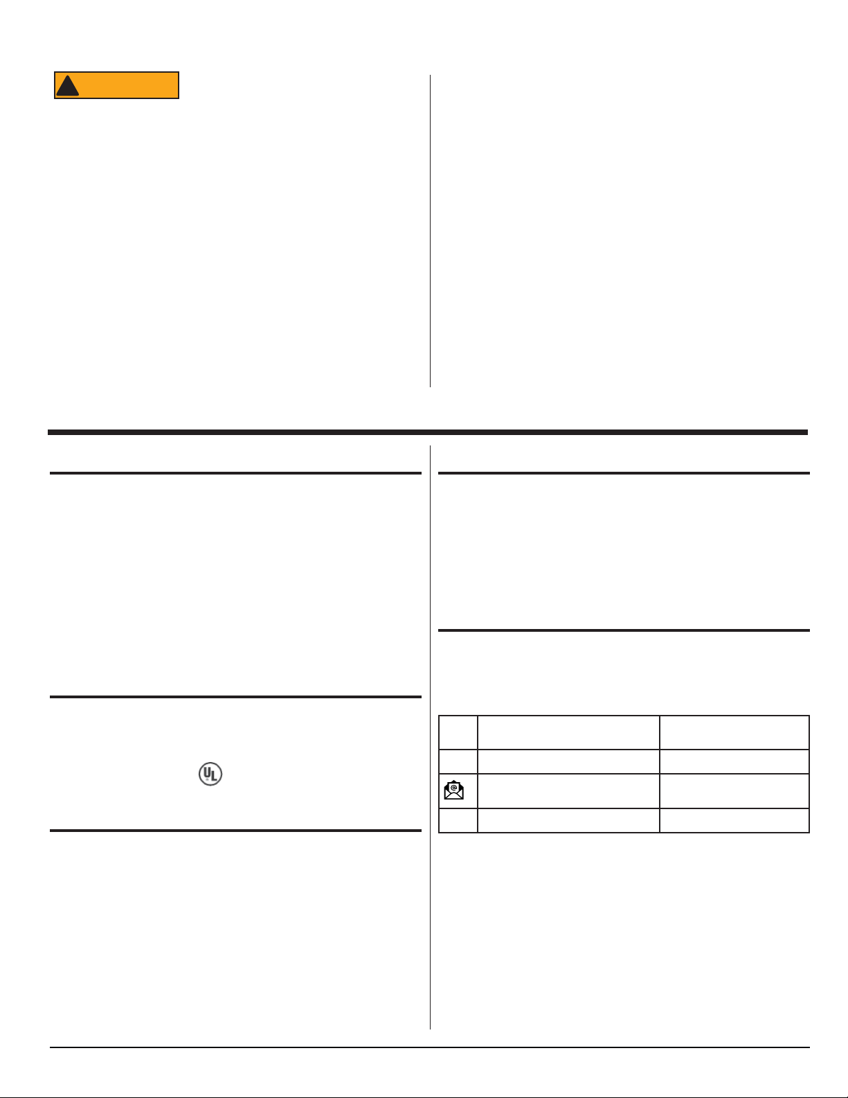
Fig. 1 - Refrigerator information label location
A Serial Number
B Model Number
C Amount of refrigerant in cooling system
D DC Voltage / Amperage
SPECIFICATIONS
N10DCX - Electronic
ON/OFF, Mode, Temperature Set
Multiple LED indicator lights
Five (5) Temperature Settings (Separate settings for freezer and fresh food compartments)
Night Mode
Rough Opening Dimensions ------------------59.88 - 60.01 high x 23.50 - 23.63 inched wide x 24.00 inches deep
Internal Capacity
Total capacity -------------------------------------------------------------------------------------------------------------- 9.7 cubic feet
DC (Direct Current) Specifi cations
Electronic Controls DC voltage input requirement ----------------------------------------------------------- 10.4 to 15.4 VDC
Minimum (cut-out) --------------------------------------------------------------------------------------------------------- 10.4 VDC
Restart (cut-in) -------------------------------------------------------------------------------------------------------------- 11.7 VDC
DC Fuse Requirements
DC Power Supply In-Line Fuse ----------------------------------------------------------------------------------------------- 15 A
DC Resistance / Amperage Ratings
Exterior Cooling Fan ----------------------------------------------------------------------------------------------------------- 0.18A
Interior Fan ------------------------------------------------------------------------------------------------------------------------- .09A
Interior Light ------------------------------------------------------------------------------------------------------------------------ .13A
Off-level Operating Limits
Side-to-side ------------------------------------------------------------------------------ 10 degrees maximum at refrigerator
Front-to-back ---------------------------------------------------------------------------- 10 degrees maximum at refrigerator
N10DCX
4
www.norcold.com
Page 5
Exploded Views
A
E
D
B
C
F
G
H
I
J
NOR000947A
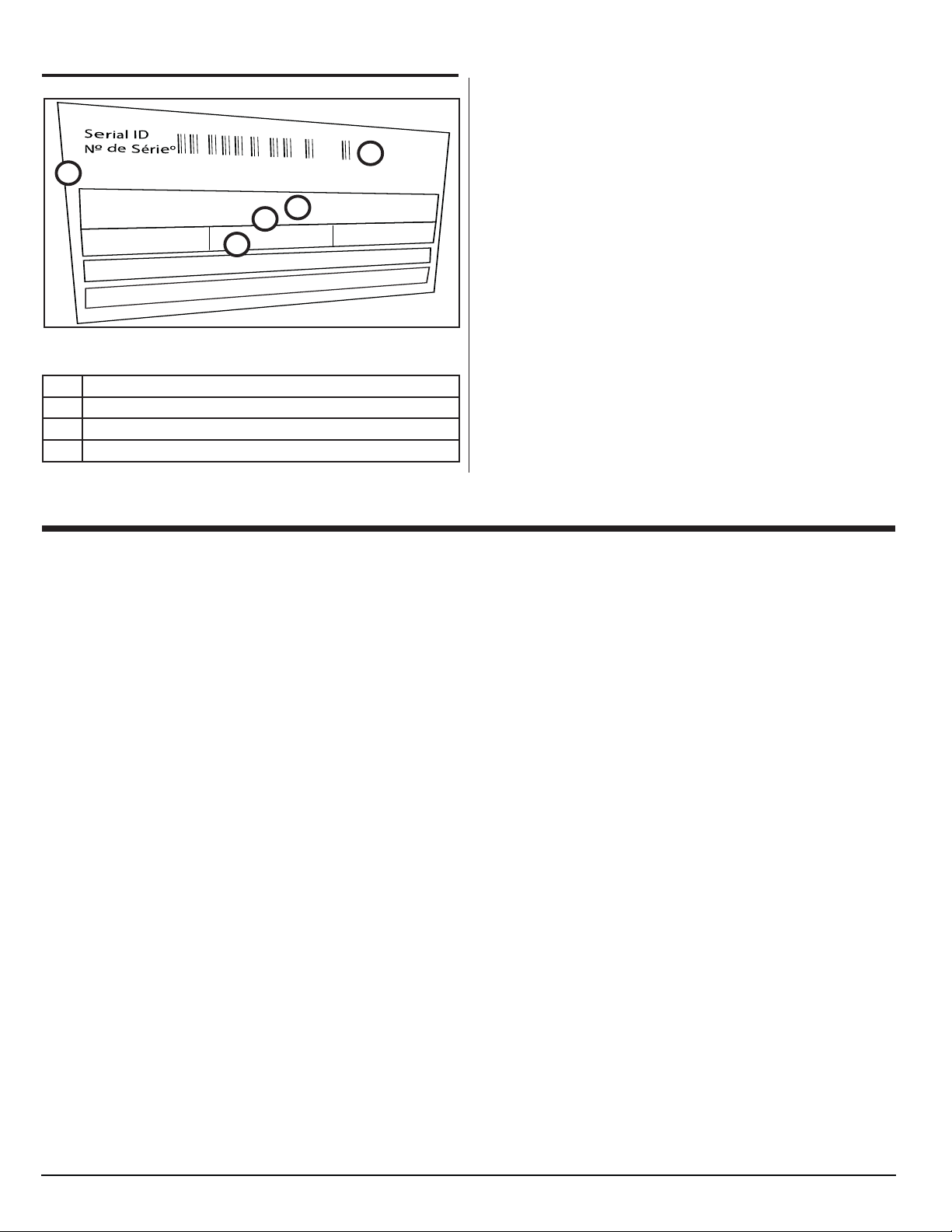
Fig. 2 - Front view
No. Description
A Control Panel
B
C
D
E
F
G Light Housing
H Light
I Light Cover
J Door Light Switch
Control Panel Label
Control Board
Control Housing
Control Housing Bracket (3x)
Fan and Housing
www.norcold.com
5
SERVICE MANUAL
Page 6
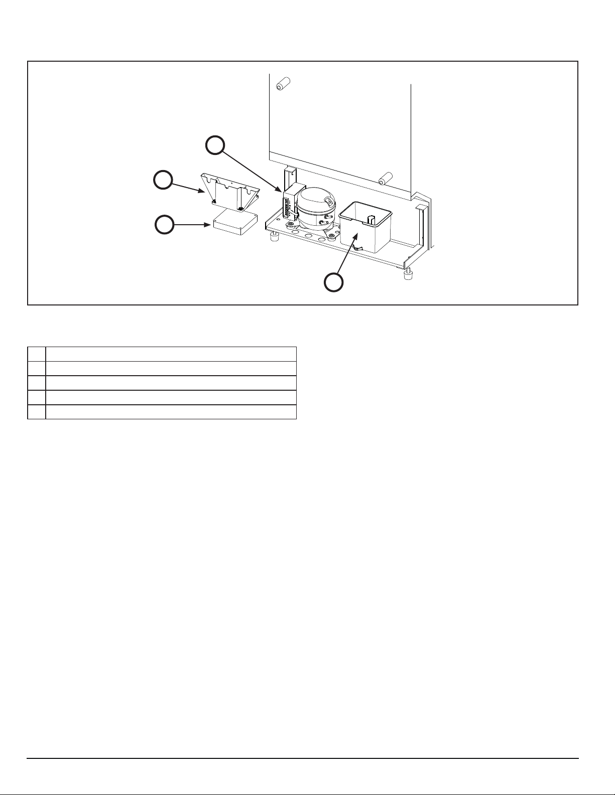
Exploded Views, cont’d.
Fig. 3 - Rear view
D
A
B
NOR000948A
C
No. Description
A Exterior Fan Vent
B Exterior Fan
C
Drip Cup
D
Control Module
N10DCX
6
www.norcold.com
Page 7
GENERAL INFORMATION
Installation
To confi rm that installation is adequate, make sure:
■ Ventilation is adequate. Refer to "Ventilation" section.
■ Electrical components are installed and operating in a safe
condition.
■ Refrigerator is installed on a solid and level fl oor (not on carpet)
and secured.
■ The fl oor is able to support the weight of the refrigerator and all
of its contents.
Ventilation
Overview
The refrigerator is made for a built-in installation. Correct ventilation
is necessary for the correct operation of the refrigerator and to
increase the life of the refrigerator cooling system.
Ventilation allows the natural fl ow of air that is necessary for good
ventilation. Cooler air comes in through the lower vent, goes
around the refrigerator coils where it removes the excess heat
from the refrigerator components , and goes out through the upper
vent / control cover. If this air fl ow is blocked or decreased, the
refrigerator will not cool correctly. Do not install the refrigerator in a
completely enclosed area such as a closet or a cabinet.
The refrigerator has built-in vents at
!
ATTENTION
WARNING
the top and the bottom. Make sure that
the air fl ow through these vents is not
blocked in any way. Blockage of the air
fl ow through these vents can:
12 Volts DC Electrical Connection
To reduce the risk of electrical interference from other DC
appliances and induction from voltage spikes:
■ The refrigerator must have an independent 12 volt supply and
not be on the same circuit as other DC appliances.
■ Route the DC power supply wires, including the fuses, directly
from the battery to the refrigerator.
The use of a battery in parallel and
!
CAUTION
■ Power converters or battery chargers used to supply DC power
are examples of installations that should have parallel battery
operation.
■ If an electrically fi ltered DC power converter is used as the sole
source of power, it must have a maximum DC ripple voltage of
less than or equal to 250mV.
Polarity
!
CAUTION
■ Connect the DC (positive) supply wire from the battery to the
red wire of the refrigerator.
■ Connect the DC (negative) supply wire from the battery to the
black wire of the refrigerator.
between the refrigerator and any
electrically fi ltered DC power converter or
battery charger used to supply DC power
to the refrigerator is recommended.
If the DC leads are installed incorrectly,
the refrigerator will not operate.
www.norcold.com
■ Shorten the life of the refrigerator cool-
ing system.
■ Cause poor cooling performance of the
refrigerator.
■ Cause continuous operation of the
refrigerator cooling system.
■ Cause fast battery discharge.
■ Void the refrigerator warranty.
SERVICE MANUAL
7
Page 8
DIAGNOSTICS
Diagnostic Pre-Checks
Diagnosing problems begins by starting with the basics. In many
cases, the problem can be solved by verifying the unit is operating
in acceptable conditions. Before performing detailed diagnostics
make sure:
■ The refrigerator is turned ON.
■ The door is closed and sealing correctly.
■ The refrigerator is correctly installed and the vents are not
blocked.
■ The vehicle fuse or circuit breaker is intact.
There may be more than one (1) over-
NOTICE
■ The ambient temperature is not unusually high (more than 110°
F. / 43° C.).
■ The air circulation inside the refrigerator is not decreased by
foods or by shelves that are covered with plastic, paper, etc.
■ The freezer is defrosted.
current device in the refrigerator supply
circuit. Be sure to check both the RV and
refrigerator.
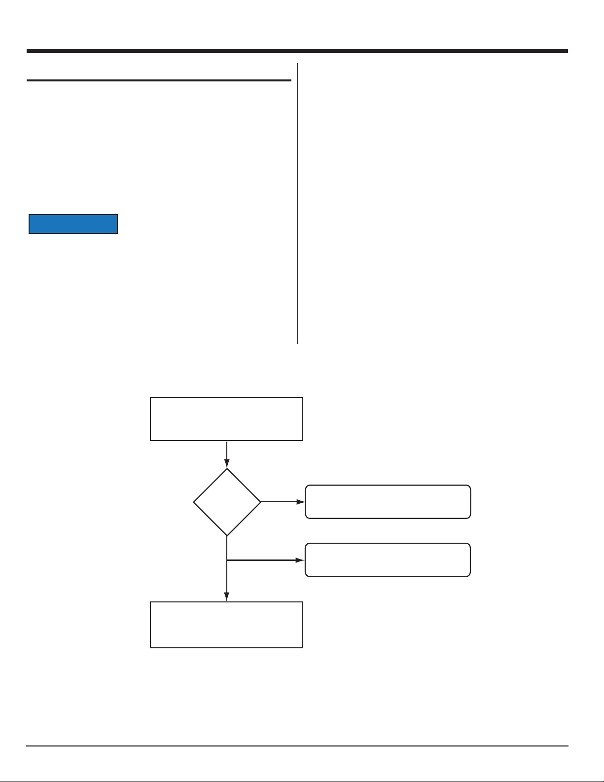
Then do the following procedure.
NOR000832B
Do the tests in “Self - Test
Diagnostics” section.
Are any
error codes
found?
YES
NO
If necessary, remove the
refrigerator from the enclosure.
Refer to the “Refrigerator Enclosure”
section.
Refer to “Self - Test Diagnostic Chart.”
Refer to “Diagnostic Symptom Chart.”
N10DCX
8
www.norcold.com
Page 9
Self-Test Diagnostics
The unit’s control module is equipped with a "Self-Test Diagnostic"
function which can be read using light emitting diode (LED) and
terminal connectors.
T able of LED References
References for Figs. 4.1 - 4.6
No. Description
A 10 mA LED With Wire Leads
A1 Black LED Wire (with connector attached)
A2 Red LED Wire (with connector attached)
B 1/4 Inch Push-On Female Connector (2x)
C 1/4 Inch Adapter With One (1) Female and Two (2) Male Connections
D 12 VDC Input Wire
E Positive (+) Terminal “+” of Control Module
F Terminal “D” of Control Module
G Control Module
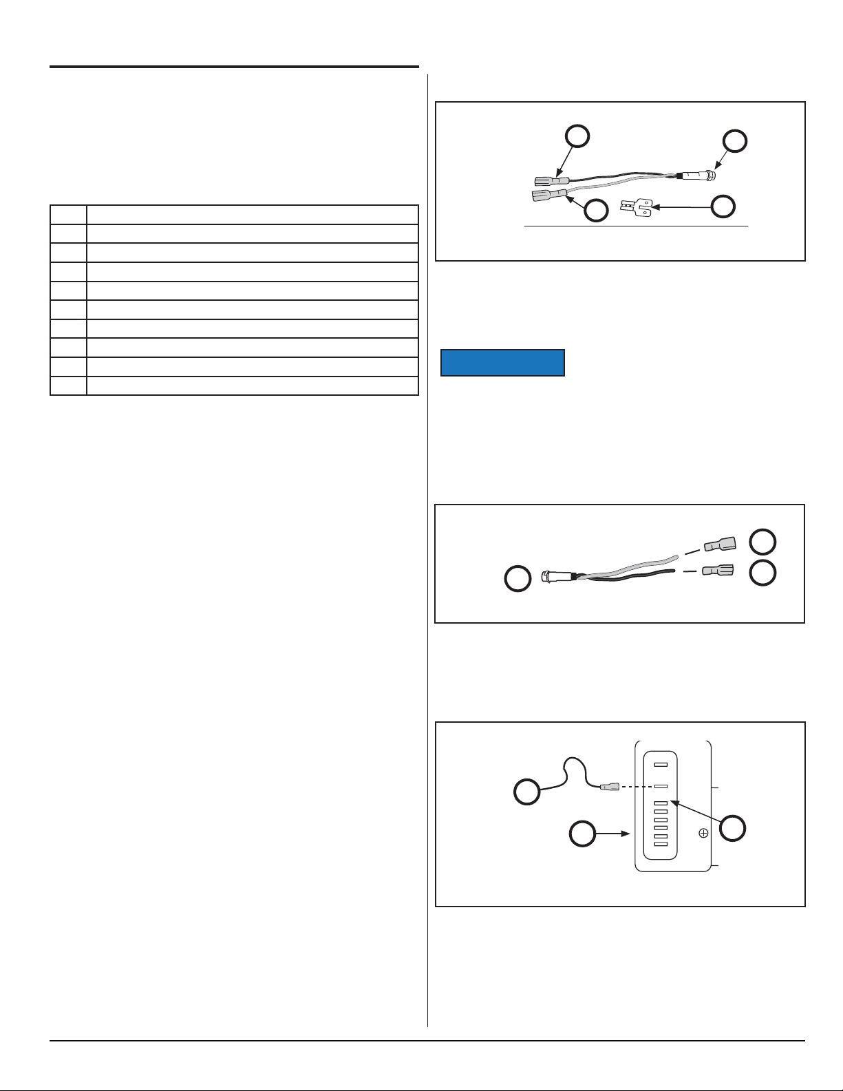
Prepare to Connect the LED
You will need the following to conduct self-diagnostics:
B
N000033A
B
Fig. 4.1 - LED
■ A 10 mA LED with wire leads (See Fig. 4.1, A).
■ Two (2) 1/4 inch push-on female connectors (See Fig. 4.1, B).
■ A 1/4 inch adapter with 1 female to 2 male connections. (See
Fig. 4.1, C)
Do not leave jumpers in place for normal
NOTICE
operation.
A
C
Conducting the LED Evaluation
Follow the steps below. If an error code is activated in the control
module (Fig. 4.3, G) and the LED (Fig. 4.1, A) is connected, it will
fl ash a number of times. The number of fl ashes will depend on
what error was recorded. Each fl ash will last 1/4 second and after
the code is fl ashed there will be a delay, then the code will repeat.
Write down all error codes; then refer to "Self-Test Diagnostic
Chart" in this section.
Connect the LED
Refer to Figs. 4.2- through 4.6
Step 1. Attach Female Connectors.
A
N000019A-1
Fig. 4.2 - Female connectors
Attach a female connector to each LED wire lead.
Step 2. Disconnect 12 VDC
D
G
NOOOO19A-2b
_
12/24 Vdc
+
+
F
D
C
P
T
B
B
E
www.norcold.com
Fig. 4.3 - 12 VDC
Disconnect the 12 VDC input wire from the positive terminal of the
control module.
SERVICE MANUAL
9
Page 10

Self -Test Diagnostics, cont’d.
Step 3. Connect Adapter
_
12/24 Vdc
NOOOO19A-3b
C
+
+
F
D
C
NOOOO19A-3b
P
T
E
Fig. 4.4 - Adapter
Connect the adapter to the positive terminal of the control module.
Self-Test Diagnostic Chart
Flashes Description Action
1 Battery Protection Cut-Out.
The voltage is outside the cut out setting.
2 Fan Over current Cut-Out.
The fan electrical load is more than 1.0 amp.
3 Motor Start Error.
The rotor is blocked or the differential pressure in the
refrigeration system is too high ( >5 bar).
4 Minimum Motor Speed Error.
The motor can not maintain minimum speed (1850 rpm).
5 Thermal Cutout of Electronic Unit.
The electronic unit is running too hot.
6 Controller Hardware Failure
Controller detects abnormal parameters
Perform
T est A.
Perform
Test B.
Perform
Test C.
Perform
Test D.
Perform
Test E.
Perform
Test K.
Step 4. Connect LED
_
12/24 Vdc
+
+
F
D
C
P
T
C
NOOOO19B-4b
A2
A1
F
Fig. 4.5 - LED
Connect the black LED wire to one side of the adapter; connect the
red LED wire to terminal “D” of the control module.
Step 5. Connect 12VDC
C
_
12/24 Vdc
+
+
F
NOOOO19A-5b
D
C
P
T
D
Fig. 4.6 - 12VDC
Connect the 12 VDC input wire to the other side of the adapter.
Diagnostic Symptom Chart
Problem Possible Cause Action
to Take
Not cooling, not
turning on.
Refrigerator gets
too cold.
Refrigerator
builds frost inside.
Runs, but does
not cool properly.
Will not run on
DC power.
Voltage within
range; refrigerator
cuts out.
- Faulty thermistor.
- No power to control module.
- Faulty wire from control module to compressor
- Faulty control module.
- Faulty Compressor.
- Bad capillary tube position.
- Faulty thermistor
- Faulty control module.
- Door not closed.
- Damaged door gasket.
- High ambient temperatures .
- Blocked air ventilation.
- Frost build up.
- Condenser coil restricted.
- Faulty condenser fan.
- Faulty cooling unit.
- Blown fuse in DC circuit.
- Undersized wiring to refrigerator, minimum #12
gauge wire required.
- Refer to Owner's Manual for recommended wire
size.
- Partially discharged battery, voltage below 11.3
VDC at compressor module.
- High resistance (voltage drop) in supply circuit.
- Parts can cause a + / - 10 VDC which can cause
refrigerator voltage to register within specifi cation,
but cutout because of part variance.
Perform
Test F.
Perform
Test G.
Perform
Test H.
Perform
Test I.
Perform
Test J.
Perform
Test K.
NOTICE
N10DCX
Do NOT leave jumpers in place for
normal operation.
Electronic Controls Fault Code Chart
Fault Code Fault Code Meaning Action to Take
E1
E2
The thermistor in the fresh food compartment is not cycling properly.
The thermistor in the freezer compartment
is not cycling properly.
E3 The voltage is outside the cut out setting.
E4
The fresh food compartment door has
been open for more than two (2) minutes.
Refer to "Fault Code "E1"" on page 24.
Refer to "Fault Code "E2"" on page 25.
Refer to "Fault Code "E3"" on page 26.
Refer to "Fault Code "E4"" on page 26.
www.norcold.com
10
Page 11

TROUBLESHOOTING
Troubleshoot Compressor Control Module
T est A, Battery Protection Cut-Out
Before starting this procedure make sure the DC supply voltage to
the refrigerator is correct. The DC supply voltage must be:
■ More than 11.7 VDC to start.
■ Remain between 10.4 VDC to 15.4 VDC to continue operation.
Make sure that the DC supply voltage
is correct.
Remove refrigerator from enclosure,
but do not disconnect the DC supply.
Inspect the fuse on the positive DC
Supply that is connected to control
module terminal “+”.
NOR000950A
Is the fuse
intact?
NO
YES
With the refrigerator turned OFF,
measure voltage at the DC connector.
VDC
10.4 - 15.4?
NO
YES
With freezer and fresh food
compartments at temperature
setting “5”, measure voltage at DC
connector.
Replace the fuse. Test the refrigerator.
Repair DC supply voltage.
Test the refrigerator.
www.norcold.com
VDC
10.4 - 15.4?
YES
Continued on next page.
NO
Repair DC supply voltage.
Test the refrigerator.
SERVICE MANUAL
11
Page 12

Troubleshooting Compressor Control Module, cont’d.
Continued from previous page.
With freezer and fresh food
compartments at temperature
setting “5”, measure voltage at
terminal “+”.
YES
NOR000950A
VDC
10.4 - 15.4?
NO
Repair refrigerator power cord.
Test the refrigerator.
Replace control module.
Test refrigerator.
N10DCX
12
www.norcold.com
Page 13

Troubleshooting Compressor Control Module, cont’d.
T est B, Fan Over Current Cut-Out
Remove refrigerator from enclosure,
but keep DC power supply connected.
With freezer and fresh food
compartments at temperature
setting “5”, make sure that the
exterior cooling fan is operating.
Is the fan
operating?
NO
Measure DC voltage at control
module terminal “+”.
VDC
10.4 - 15.4?
NO
NOR000951A
YES
YES
Replace the refrigerator.
Fan has failed. Replace the fan.
Replace control module.
www.norcold.com
13
SERVICE MANUAL
Page 14

Troubleshooting Compressor Control Module, cont’d.
T est C, Motor Start Error
Complete the “Diagnostic Pre-Checks.”
Remove refrigerator from enclosure,
but keep DC power supply connected.
Turn refrigerator OFF for a minimum
of five (5) minutes to allow internal
system pressures to equalize.
Turn refrigerator back ON.
NOR000952A
Does code
3 return?
NO
YES
Replace the refrigerator.
Repair complete.
N10DCX
14
www.norcold.com
Page 15

Troubleshooting Compressor Control Module, cont’d.
T est D, Minimum Motor Speed Error
Complete the “Diagnostic Pre-Checks.”
Remove refrigerator from enclosure,
but keep DC power supply connected.
Make sure the:
- Upper and lower vents are not
blocked.
- The refrigerator is not overloaded
with hot items.
- The ambient operating temperature
is lower than 110°F (43° C).
NOR000953A
Is
VDC
10.4 - 15.4?
YES
Is
unit
overloaded?
NO
Is fan
operating,
coils clean/not
blocked?
NO
NO
YES
YES
Correct input voltage.
Reduce load on unit.
Replace the refrigerator.
Replace control module.
www.norcold.com
15
SERVICE MANUAL
Page 16

Troubleshooting Compressor Control Module, cont’d.
T est E, Thermal Cut-Out of Electronic Unit
The control module has a built in thermal
NOTICE
protection which stops the compressor
operation if the control module circuit
board temperature is higher than 203° F
(95° C). The refrigerator will not restart
until the control module circuit board
temperature is lower than 185° F (85° C).
Remove refrigerator from enclosure,
but keep DC power supply connected.
Make sure the:
- Upper and lower vents are not
blocked.
- Condenser coil is clean.
- Fan is operating.
- Ambient operating temperature
is lower than 110°F (43° C).
Test the unit.
NOR000954A
Does code
5 return?
NO
YES
Replace control module.
Repair complete.
N10DCX
16
www.norcold.com
Page 17

Troubleshoot Symptoms
T est F, Not Cooling, Not Turning On
Complete the “Diagnostic Pre-Checks.”
Remove refrigerator from enclosure,
but keep DC power supply connected.
Any wires
disconnected
from
terminals?
YES
NO
Turn refrigerator ON. The blue
“ON” indicator light should come on.
Does light
come on?
YES
NO
Is unit
connected to
DC power?
YES
Refer to “Wiring Diagram.” Connect wire.
Test unit.
Examine DC fuse. Replace if necessary.
NOR000955A
www.norcold.com
NO
With the refrigerator turned “OFF”,
use a DVOM to check input voltage.
The input voltage must be higher
than 11.7 VDC.
Is input
voltage
correct?
NO
YES
Continued on next page.
Correct input voltage. Test unit.
SERVICE MANUAL
17
Page 18

Troubleshooting Symptoms, cont’d.
Continued from previous page.
YES
Make sure the DC input is connected
correctly:
- Positive lead to “+” terminal.
- Negative lead to ”-” terminal.
Is input
connected
correctly
NO
YES
Remove control module and control
module base. Remove compressor
interface cover. Unplug compressor
wire harness at each end. Check
continuity of compressor wire harness.
Is
compressor
wire harness
OK?
NO
YES
With compressor harness unplugged
from the compressor, measure
resistance between all three (3) current
lead-in pins on the compressor.
Correct input connections. Test unit.
Replace compressor wire harness.
Test unit.
N10DCX
NOR000995A
Are
measured
values about
the same?
NO
YES
Replace the control module.
Replace the refrigerator.
www.norcold.com
18
Page 19

Troubleshooting Symptoms, cont’d.
T est G, Refrigerator Gets Too Cold
Complete the “Diagnostic
Pre-checks.”
Does the control
display show an E1
or E2 error?
YES
Are thermistors connected?
NO
Reconnect thermistors. Test unit.
YES
Remove refrigerator from enclosure,
but keep DC power supply connected.
Refer to the “Wiring Diagram” section.
Are the thermistors and magnet valve
connected the control board?
YES
Replace thermistor of compartment
that is too cold.
NOR000956B
NO
Reconnect thermistor and/or magnet
valve. Test unit.
YES
Did
unit stop
operating?
YES
NO
Disconnect wires at control module
terminals”C” and “T”.
Did unit stop operating?
NO
Is the magnet valve bad?
NO
Replace the thermistor.
YES
YES
Repair shorted wires between optical
display module and control module.
Test unit.
Replace the refrigerator.
www.norcold.com
Replace the control module. Test unit.
SERVICE MANUAL
19
Page 20

Troubleshooting Symptoms, cont’d.
T est H, Refrigerator Builds Frost Inside
These models are not frost free units
NOTICE
and the unit will have to be defrosted
at times. If the unit seems to have an
excessive amount of frost or it is building
quickly perform the following tests.
Check temperature setting of freezer
and fresh food compartments.
NOR000957B
Inspect door seal, hinges, and latch
for correct operation.
All
operating
correctly?
NO
Repair as needed. Test refrigerator.
N10DCX
20
www.norcold.com
Page 21

Troubleshooting Symptoms, cont’d.
T est I, Runs But Does Not Cool Properly
Check the temperature setting of
freezer and fresh food compartments.
Remove refrigerator from enclosure,
but keep DC power supply connected.
Inspect condenser coil for restriction.
Is it
restricted?
Check for 12 VDC at terminal (+) on
the control module.
Is voltage
correct?
NOR000958B
Replace control module.
NO
NO
YES
YES
Remove restriction. Clean as needed.
Fan has failed. Replace refrigerator.
www.norcold.com
21
SERVICE MANUAL
Page 22

Troubleshooting Symptoms, cont’d.
T est J, Will Not Run On DC Power
Check for blown fuse in DC circuit.
Is fuse
blown?
YES
NO
Check that the wiring to the refrigerator
is at least #12 gauge wire (required).
Is wiring at
least #12
gauge?
NO
YES
Check DC voltage at control module.
Is voltage
below 10.4
VDC?
NO
Replace fuse.
Refer to the Installation Manual for
the recommended wire size.
Correct high resistance (voltage drop) in
supply circuit.
N10DCX
YES
Recharge or replace battery.
NOR000959A
www.norcold.com
22
Page 23

Troubleshooting Symptoms, cont’d.
T est K, Voltage Within Cutout Range but Refrigerator
Cuts Out
Complete the “Diagnostic Pre-Checks.”
Remove refrigerator from enclosure,
but keep DC power supply connected.
Make sure:
- Upper and lower vents are not
blocked.
- The refrigerator is not overloaded
with hot items.
- The ambient operating temperature
is lower than 110°F (43° C).
Measure input voltage.
- 12 VDC nominal inout voltage is
10.4 - 15.4 VDC.
Is input
voltage
10.4 - 15.4
VDC?
NO
YES
NOR000960A
Is
unit
overloaded?
YES
NO
Disconnect thermistor wire from
terminal “C” on the cooling unit
control module. Test the refrigerator.
Does the refrigerator still cut out?
YES
Contact Customer Service.
Correct input voltage.
Reduce load on unit.
NO
Repair complete.
www.norcold.com
23
SERVICE MANUAL
Page 24

Troubleshoot Electronic Controls Fault Codes
Fig. 5 - Mode Button will display Electronic Controls Fault Codes
Fault Code - "E1"
Complete the “Diagnostic Pre-Checks.”
Make sure thermistor in the fresh food
compartment is connected.
Remove thermistor cover in fresh food
compartment and check connection of
thermistor wire to thermistor.
Is
thermistor
wire
connected?
NO
YES
Check connection of thermistor wire to
the refrigerator electronic controls.
Refer to the wiring diagram.
E1
Possible Cause:
The fresh food thermistor is not
cycling properly.
Correct connection.
N10DCX
NOR000978A
Is
thermistor
wire
connected?
YES
Replace Thermistor.
NO
Correct connection.
www.norcold.com
24
Page 25

Troubleshooting Electronic Control Fault Codes, cont’d.
Fault Code - "E2"
Complete the “Diagnostic Pre-Checks.”
Make sure thermistor in the freezer
compartment is connected.
Remove thermistor cover in freezer
compartment and check connection of
thermistor wire to thermistor.
Is
thermistor
wire
connected?
NO
YES
Check connection of thermistor wire to
the refrigerator electronic controls.
Refer to the wiring diagram.
E2
Possible Cause:
The freezer thermistor is not
cycling properly.
Correct connection.
NOR000979A
Is
thermistor
wire
connected?
YES
Replace Thermistor.
NO
Correct connection.
www.norcold.com
25
SERVICE MANUAL
Page 26

Troubleshooting Electronic Control Fault Codes, cont’d.
Fault Code - "E3"
Correct the DC input voltage to the refrigerator. Make sure the
input voltage is 12.0 VDC.
Fault Code - "E4"
Make sure:
■ the light switch closes when the door closes.
■ all of the connections to the refrigerator electronic controls are
intact.
E3
Possible Cause:
The voltage is outside the cut-out
setting.
E4
Possible Cause:
The door has be open for more
than two (2) minutes.
N10DCX
26
www.norcold.com
Page 27

WIRING DIAGRAM
H
K
WH/BC
NOR000949A
BR/BN
+
-
B
Fig. 6 - Wiring diagram
Item Description
A Display Module
B 12 VDC Input
C 15A Fuse
D Main PCBA Cooling Unit
E Exterior Fan
F Freezer Compartment Thermistor
G Fresh Food Compartment Thermistor
H Interior Light
I Interior Fan
J Interior Light Switch
K Magnet Valve
I
BK/NR
DCFDCF
J
A
F
G
WH/BC
RD/RG
FUSE
WH/BC
C
+-+
F
T
P
D
C
D
WH/BC
WH/BC
WH/BC
BK/NR
BK/NR
RD/RG
BR/BN
BL/BL
BK/NR
GND
12V
FJ2
MK
LED
12V
CN5
GND
FJ1
T12V
12V
LD
LC
CN1
CN2
CN4
RD/RG
BL/BL
E
www.norcold.com
27
SERVICE MANUAL
Page 28

REFRIGERATOR ENCLOSURE
Remove Refrigerator
1. Disconnect all power supplies to the refrigerator.
Failure to disconnect the electrical
!
ATTENTION
WARNING
2. Remove the mounting screws from each mounting bracket. Pull
the refrigerator forward.
Replace Refrigerator
1. Push refrigerator fully into enclosure. Install screw into each
mounting bracket.
2. Connect all power supplies to the refrigerator.
sources can cause dangerous personal
injury or death.
N10DCX
28
www.norcold.com
 Loading...