

Norcold DC0040, DC0040K, DC0051, DC0051K, DE0040 Service Manual
...
Refrigerator
Service Manual
Models:
DC0040(K), DC0051(K)
DE0040, DE0051
DE0240T, DE0251T
Norcold, Inc.
P.O. Box 4248
Sidney, OH 45365-4248
Part No.623011A(08/03)
Troubleshooting – Table of Contents
!
Ø Procedure A – Thermostat “ON” compressor does not run… 3
Ø Procedure B – Compressor resistance……………………….. 4
Ø Procedure C – Power supply output voltage…………………. 5
Ø Procedure D – Compressor amp draw………………………… 6
Ø Procedure E – Evaporator thermistor resistance…………….. 7
Ø Procedure F – Insufficient cooling……………………………… 8
Ø Procedure G – Refrigerator too cold…………………………… 8
Ø Procedure H – Auto shut-off device……………………………. 8
Ø Procedure I – Ventilation………………………………………… 9
Ø Wiring schematic…………………… ……………………………. 9
Ø Quick reference repair sheet……………………………………. 10
Warning
Perform all tests using a fully charged 12V DC battery.
Using other equipment that suppli es DC vol tage may
cause permanent refrigerator component failure.
2
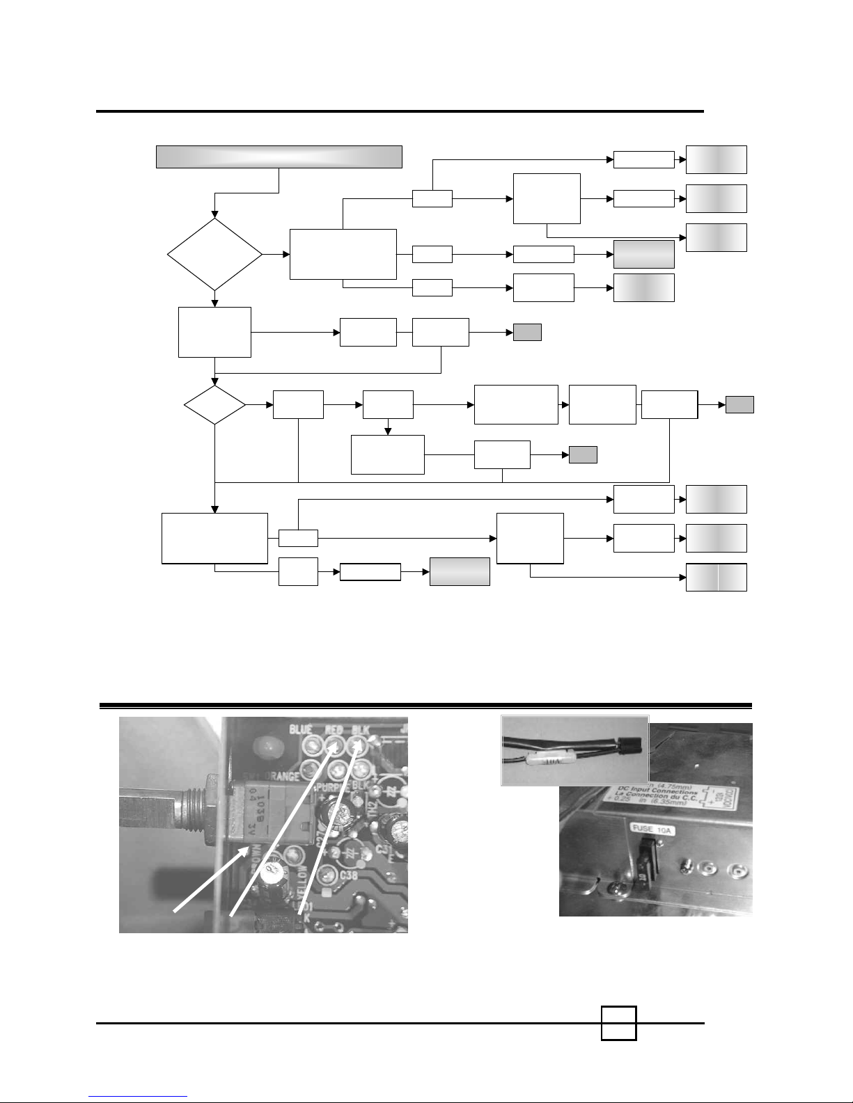
Troubleshooting – Procedure A
Thermo st at “ON ” Co mpr e sso r Doe s Not Run
DC 0V
Measure Terminal
Is Temperature
Control LED on?
NO
Check Supply
Voltage
(10.5 – 32V DC)
(85 – 132V AC)
CORRECT
Power
Source
Measure Terminal
Voltage of Temperature
Control Between TP2 &
TP3. (See Figure 1)
Note: Measurements taken with 12.8V DC or 120V AC power supply.
DC
AC
Voltage Of Temperature
Control Between TP1 &
YES
TP2. (See Figure 1)
INCORRECT
Check Both
DC Fuses
OK
OPERATION
DC 0V
DC 12
to 32V
Correct
Voltage
BLOWN
(See Figure 2)
DC
AC
OPERATION
Normal
Check DC
Polarity
OK
Replace
10A Fuse
DC 2V
DC 5V
Compressor
INCORRECT
DC
OPERATION
OPERATION
Runs
NO
See
Procedure B
Check AC
AC
YES
Power Su p ply
(37 – 45V DC)
(See Figure 5)
Normal
DC Power
Supply Failure
OK
Reverse Polarity
& Check Operation
(Red + / Black -)
Compressor
Runs
YES
NO
Check AC
Power Supply
(37 – 45V DC)
(See Figure 5)
BAD
GOOD
BAD
(See Figure 2)
OK
GOOD
Replace
10A Fuse
Short Cir cuit
Short Cir cuit
See
Procedure B
Change DC
Power Supply
Compressor
Runs
DC Power
Supply Failure
DC Power
Supply Failure
Change DC
Power Sup p ly
Change DC
Power Sup p ly
Change AC
Power Sup p ly
YES
NO
Change DC
Power Sup p ly
Change DC
Power Sup p ly
Change AC
Power Sup p ly
OK
Brown
TP1
Figure 1 – Temperature Control
Red
TP3
Black
Figure 2 – Fuse Locations
Note: If 10 Amp fuse is blown,
check wiring of vehicle.
3
 Loading...