

Page 1

UPPER & LOWER SIDE
VENT INSTALLATION
FOR NORCOLD MODELS 900/9100/N600/N800
Read these important instructions carefully . Become thoroughly acquainted with the
content before installing vents and refrigerator.
IMPORT ANT NOTE: Norcold’ s
These
Ventilation and Installation
and Installation
codes, or in the absence of local codes, with these standards:
In the United States:
- National Fuel Gas Code, ANSI Z223.1.
- Manufactured Home construction and Safety Standard, Title 24 CFR, Part 32-80.
- Standard for Recreational Vehicles, ANSI A119.2 latest edition.
In Canada:
- Current CGA B149.1 and CGA B149.2 installation code for Propane Appliances and Equip-
- Current CSA Z240.4.2 Installation Requirement for Propane Appliances and Equipment in
- Current CSA Z240.6.2/C22.2 No. 148 Electrical Requirement for Recreational Vehicles.
Upper and Lower Side Vent Installation
instructions when installing the refrigerator. Installation must conform with local
ment.
Recreational Vehicles.
Venting and Installation
instructions are in addition to Norcold’s
instructions that accompany each refrigerator. Follow the
instructions must be followed.
Venting
When installed, the refrigerator must be electrically grounded in accord with local or state codes,
the National Electrical code, and ANSI/NFP A 70. In Canada, grounding is in accord with the
Canadian Electrical Code C22.2.
LP Gas supply piping and fittings must comply with local, state, and national codes governing type
and size. These components should also comply with the current NFP A 501C section 2.41, 1990
and with the current CAN 1-6.10 Standard.
Important!
During storage of the refrigerator in the RV or the trailer , always disconnect the power
source.
Part No. 618698C (7-98)
1
Page 2
Upper and Lower Side V ent Installation
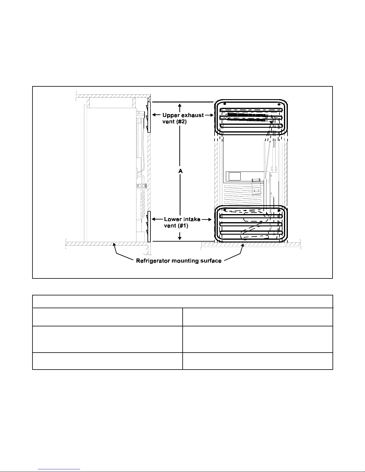
These instructions provide an alternative method for installing Norcold 6 and 8 cubic foot
refrigerators (see T able 1). This method allows for using two lower vents. The second lower vent
serves as the upper exhaust vent, replacing the roof vent. Use only those vents specified in the
refrigerator installation guide for side wall installation.
Side View Rear View
Figure 1
Refrigerator Models
8 Cubic Foot Models
982F , 9182F, 982-FIM, N820F, N821F
N841F , N841-FIM
A = 62” minimum
962F , 9162F, 962-FIM, N620F, N621F
6 Cubic Foot Models
N641F , N641-FIM
A = 55” minimum
Table 1
1. Install the lower intake vent flush with the refrigerator mounting surface (see Figure 1, #1). this
location provides the necessary ventilation from outside the vehicle.
2. Install the upper exhaust vent (see Figure 1, #2) directly above the lower vent at the A
dimension, (see Figure 1 and T able 1) for the model being installed. Position this vent directly
behind the cooling unit condenser to allow heat and exhaust from the cooling unit to vent to the
outside.
2
Page 3
V entilation Fan Installation
T o ensure ef ficient performance, a continuous air flow is required across the refrigerator’s cooling
system. A thermostat controlled fan must attach to the refrigerator’s cooling system before
placing the refrigerator in the enclosure. This fan assists air flow across the cooling system. The
thermostat turns on the fan whenever the refrigerator’s cabinet temperature reaches 95 °
Fahrenheit. Even with the fan, the air flow from the side intake vent across the refrigerator’s
cooling system to the exhaust vent must be unobstructed.
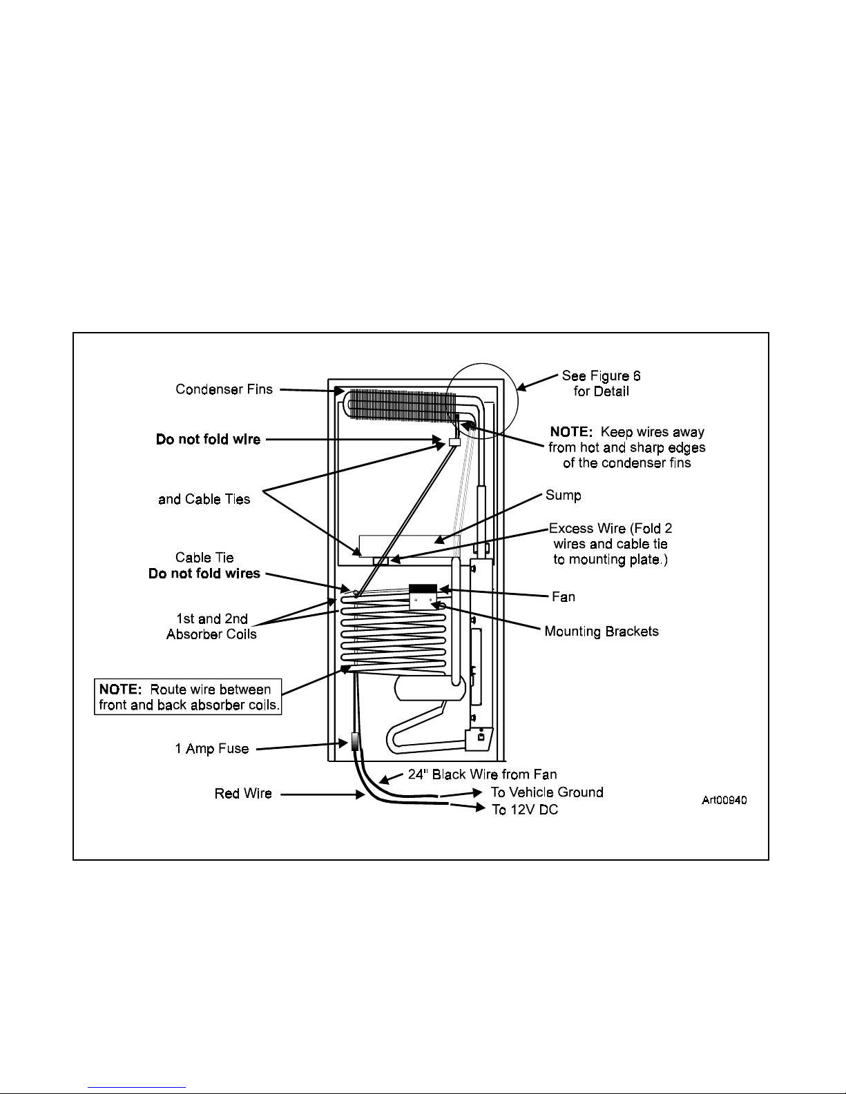
Figure 2 shows the back of the refrigerator and the location of he 1st and 2nd absorber coils.
Also in Figure 2 are items installation and their approximate locations.
Mounting Plates
Figure 2
3
Page 4
Fan Installation
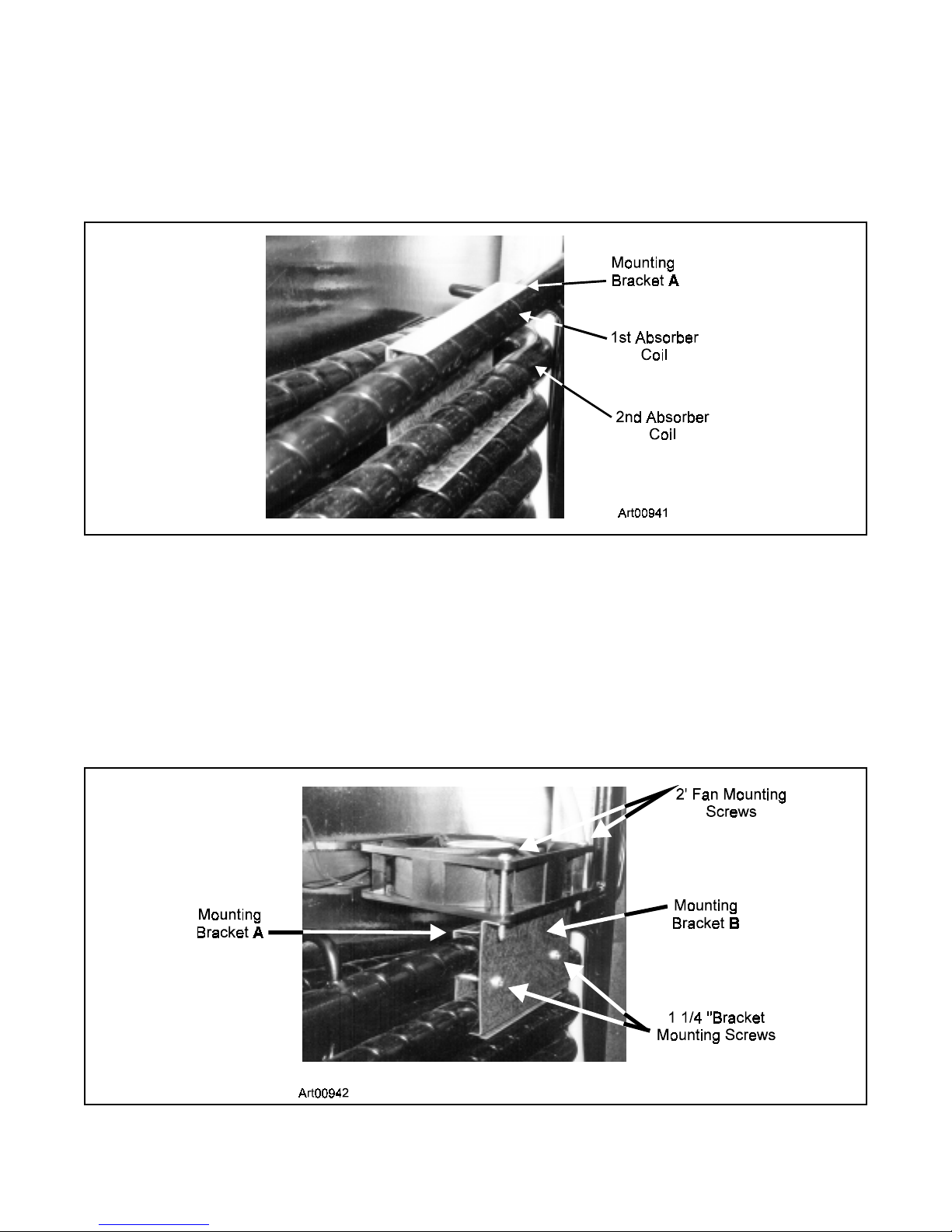
1. Position mounting bracket A (See T ools and Parts List, #I) around the top of the two absorber
coils. Make sure the wider flange of mounting bracket A is to the bottom. The flanges of
mounting bracket A face away from the refrigerator cabinet. See Figure 3.
Figure 3
2. Position mounting bracket B (See T ools and Parts List, #J) around the front of the 1st and 2nd
absorber coils. See Figure 2. This bracket has a wiring label on it. Push mounting bracket B
and mounting bracket A together .
NOTE: Mount the flange of bracket B over the bottom flange of bracket A. Insert two 1 1/4”
bracket screws. See Figure 4. DO NOT fully tighten.
Figure 4
4
Page 5
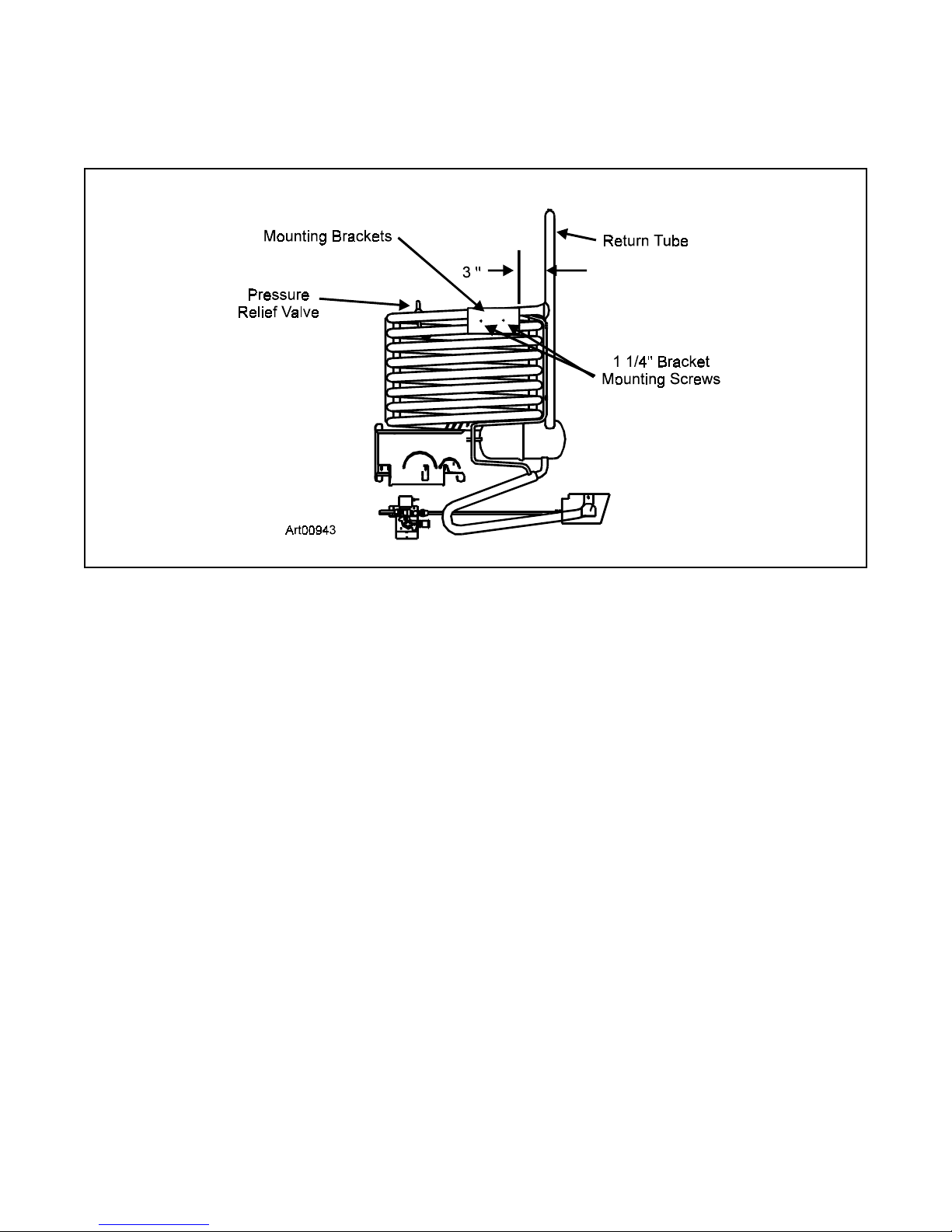
3. Slide mounting brackets along the absorber coils. Leave a 3” clearance between the right
edge of the brackets and the cooling unit’s return tube. See Figure 5.
Figure 5
4. Tighten 1 1/4” mounting bracket screws securing bracket to cooling system. See Figure 5.
5. Place 12 VDC fan on top of the mounting bracket B (label side up) and fan wires exiting to the
left side (when viewed from the back).
Insert two 2” fan mounting screws and tighten to secure fan to mounting bracket. See Figure 4.
Do not over tighten, causing plastic fan housing to crack. Ensure fan wires do not contact
the sharp edges of the bracket or are pinched in any way .
NOTE: When installing fan, leave remaining wires in plastic bag to prevent them from pinching.
5
Page 6
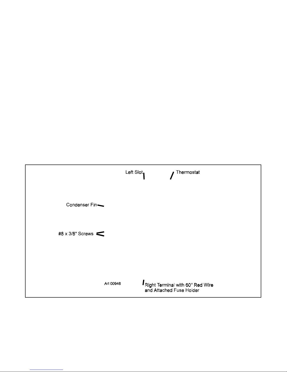
Thermostat Installation
1. Viewing the refrigerator from the rear , mount the thermostat to the right condenser fin.
Remove wires from the plastic bag. Untangle any wires that are connected to the thermostat
and the fan. Align the holes of the thermostat with the left slot in the condenser fin. See Figures
2 and 6.
IMPORT ANT : The thermostat is fragile, handle it with care. Do not hit the plastic thermostat
with the screwdriver or allow the screwdriver to slip off the screw and contact the plastic.
NOTE: The 41” red wire goes to the left terminal. The 60” red wire (and attached fuse holder)
goes to the right terminal.
2. Insert a #8 x 3/8” screw through the bottom hole of the thermostat and into the lowest point of
the left condenser fin slot. Tighten the screw 1 or 2 turns to hold the thermostat in place. See
Figure 6.
3. Insert a #8 x 3/8” screw through the top hole of the thermostat and into the condenser fin slot.
See Figure 6.
4. Tighten the screws to secure the thermostat to the condenser fin.
IMPORTANT : Do not overtighten the screws.
Figure 6
6
Page 7
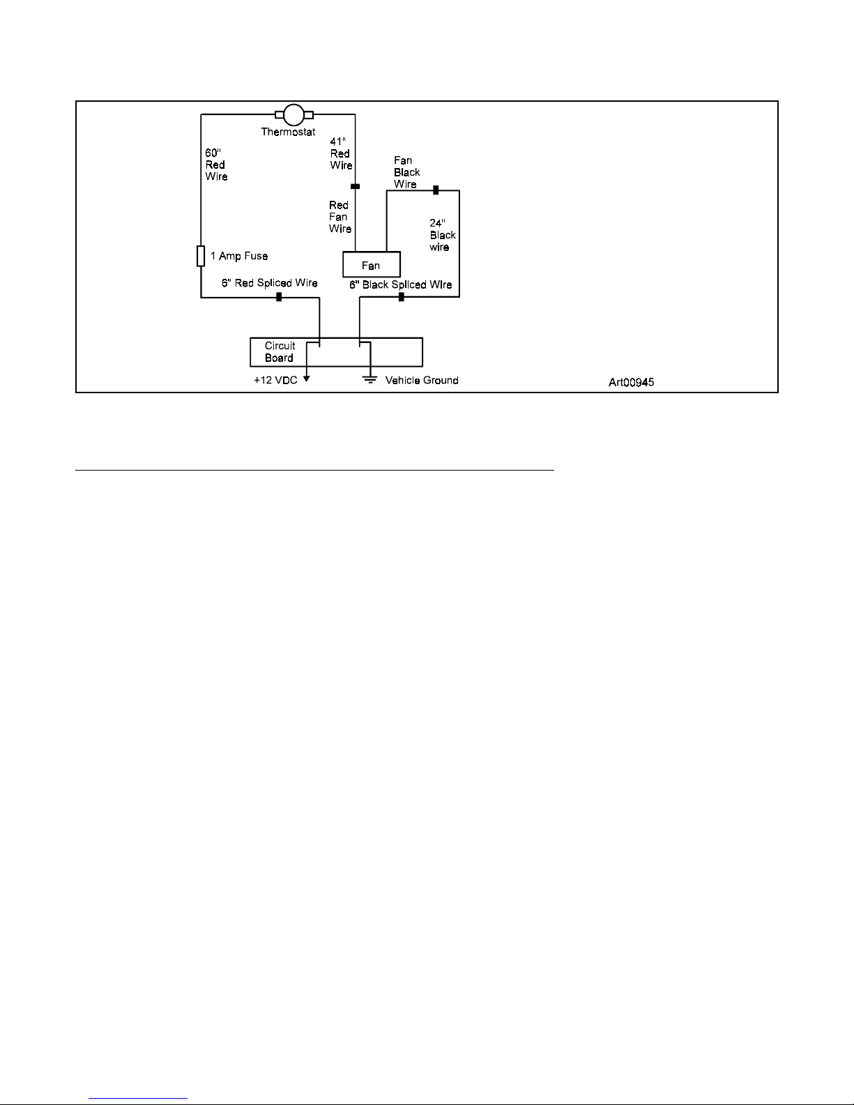
Wire Connections
Wiring:
Splice to Circuit Board (CB) (For 900, 9100, N600, N800 Models):
- Route the 6” red spliced wire and attached 60” red fused wire between the front and back
absorber coils (Figure 2).
- Connect the female end of the 6” red spliced wire to the +12 V CB (circuit board) terminal
(Figure 7).
- Route the 6” black spliced wire and attached 24” black wire between the front and back
absorber coils (Figure 2).
- Connect the female end of the 6” black spliced wire to the 12 VCOM CB ground terminal
(Figure 7).
- Secure all wires so they do not contact hot surfaces or sharp edges on the condenser fins or
absorber coils. Use cable ties and adhesive mounting plates (figure 2) as described below .
- Use a cable tie to secure the 41” red wire, the 6” red wire, and the 24” black wire to the
pressure relief valve (Figure 5).
7
Page 8

5. Pull the wires straight down from the thermostat and place a mounting plate about 12” down
from the condenser so the wires do not touch the condenser or the vertical tubing. Secure the
wires to the mounting plate with a tie wrap. Place the mounting plate under the sump and to
the left of the fan (Figure 2). Fold the excess wire as shown. Tie the folded wires to the
mounting plate under the sump with a cable tie to prevent the wires from moving by air flow.
This also prevents excess wire from getting caught between the side of the refrigerator and
theenclosure. Make sure the wires are pulled in tight between the tie wrap locations and that
the tie wraps are firmly secured.
The refrigerator is now ready for installation.
IMPORT ANT: Install the refrigerator according to Norcold’s installation instructions.
900 / 9100 / N600 / N800 Series
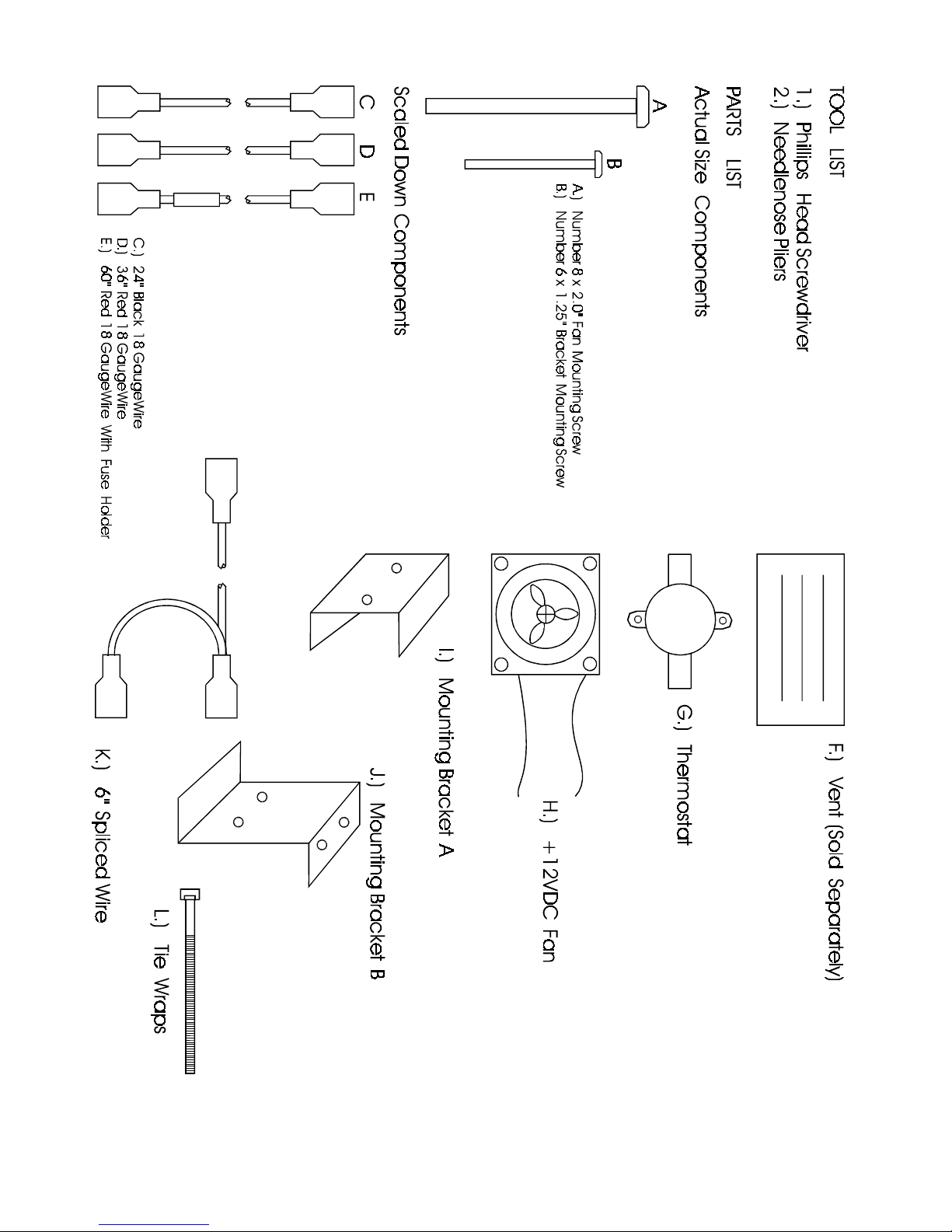
Side Wall Venting Components Required
For Assembly Kit Part Number 619020
QTY PART NUMBER DESCRIPTION
1.......618698b............. Ins tal lati on In structions
2. .....61633330............ #8 x 3/8” Thermostat Mounting Screws
2......61581 122............ #6 x 1 1/4” Bracket Mounting Screws
2........618951.............. #8 x 2” Fan Mounting Screws
1........618978.............. 6” Red Quick Connect Splice Wire #18 Gauge 4/64” Thermoplastic
Insulation
1........619017.............. 6” Black Quick connect Splice Wire #18 Gauge 4/64” Thermoplastic
Insulation
2........618950.............. Tie Rap Mounting Plate Adhesive Backed
1........619018.............. Fan Wiring Diagram Label
1........618699.............. 60” Red #18 Gauge Wire w/4/64” PVC Insulation, w/Quick Connect
Terminals, w/DC Fuse Holder
1........618700.............. 24” Black #18 Gauge Wire w/4/64” PVC Insulation, w/Quick Connect
Terminals
1........618701.............. 41” Red #18 Gauge Wire w/4/64” PVC Insulation, w/ Quick Connect
Terminals
1........618856.............. 12 VDC Fan (Brushless .30 Amps)
1........618093.............. 12 VDC Thermostat (130 On / 115 Of f)
1........619016.............. Fan Support Mounting Bracket (B)
1........618857.............. Fan Support Mounting Bracket (A)
4......61417922............ Cable Ties
1........619023.............. Package Label
1........619286.............. Thermostat Warning Note
8
Page 9
9
 Loading...