

Norcold 1200, 120-IM Service Manual
INC.
Service Manual
Gas/Electric Refrigerators
MODELS
1200XX
120X-IMXX
WARNING
!
DO NOT install this refrigerator in below deck marine applications. Do not
install this refrigerator in fixed indoor cabin or other dwelling applications. This
refrigerator must use only NORCOLD designed and approved outside air intake and exhaust ventilation for correct and safe operation. Any other ventilation could cause lethal combustion exhaust fumes and or/explosive propane
gas fumes to be in the living area and/or below deck.
© 2005 THETFORD CORP ., NORCOLD, INC. All rights reserved.
Publication No. 618968B (02-18-05)
TABLE OF CONTENTS
Introduction ------------------------------------------------------ 1
About this Manual ................................................................. 1
Model Identification .............................................................. 1
Information Label ................................................................. 1
Cooling Unit Serial Number ................................................1
Certification and Code Requirements ................................ 1
About Installation .................................................................1
Replacement Parts .............................................................. 1
Technical Assistance ........................................................... 1
Safety Awareness---------------------------------------------- 3
Safety Notice......................................................................... 3
Attention Statements ............................................................ 3
Safety Statements ................................................................ 3
Specifications --------------------------------------------------- 4
1200XX/120X-IMXX Models ..................................................4
Troubleshooting – Quick Reference Guide------------ 5
Displayed Fault Codesr -------------------------------------- 6
Troubleshooting Flowchart s-------------------------------- 8
Blank Display – Refrigerator does not turn on .................... 8
no LP - no FL Fault Code – Burner failed to ignite or
reignite.................................................................................. 9
dc LO Fault Code – Low dc voltage................................... 10
Sr FS - Sr Fault Code – Flame sense circuit failure ......... 10
dc HI Fault Code – DC voltage high .................................. 11
Sr CL - AC rE Fault Code – AC relay stuck closed............ 11
no AC Fault Code – No AC power available...................... 12
AC LO Fault Code – AC voltage low ..................................13
AC HI Fault Code – AC voltage high.................................. 13
AC HE Fault Code – AC heater failed open ...................... 14
Food Compartment Lamp Switch .....................................15
Lamp Switch Operation.................................................... 15
dr Fault Code – Door open for more than 2 minutes .......15
Lamp Switch Testing Procedure ......................................15
Thermistor Failure Fault – Controls in Backup Operating
System mode ..................................................................... 16
Backup Operating System (BOS) ......................................16
1200XX/120X-IMXX Backup Operation .......................... 16
Power Board Resetting Procedure ................................... 17
no co Fault Code – No cooling detected by the controls - S/
N 832171 and higher .........................................................17
Ventilation-------------------------------------------------------18
Roof Exhaust Venting......................................................... 18
Air Intake Vent .....................................................................18
Roof Exhaust Vent.............................................................. 18
Baffles.................................................................................19
Vertical Angled Baffles .....................................................19
Double Sidewall Venting ....................................................20
Air Intake Vent ..................................................................20
Sidewall Exhaust Vent ...................................................... 20
LP Gas System------------------------------------------------- 2 3
Pressure Requirements ....................................................23
Components ...................................................................... 24
Testing for LP Gas Leaks ..................................................24
Solenoid Gas Valve .........................................................24
Solenoid Gas Valve Connections ....................................24
Replacing Old Style Gas Valve .......................................24
Orifice................................................................................25
Burner ............................................................................... 25
Burner Tube ...................................................................... 25
Flue ................................................................................... 26
Flue Cap ........................................................................... 26
Flue Baffle......................................................................... 26
Flame Appearance .............................................................26
Burner Cleaning Procedure ...............................................27
Electrical Requirements and Components ----------- 2 8
DC Voltage Requirements and Polarity ............................28
Power Board DC Fuse......................................................28
DC Power Wiring Requirements .......................................28
AC/DC Converter as Power Source .................................. 28
Lamp Assembly ...............................................................28
Divider Heater ..................................................................28
AC Power Requirements ................................................... 29
AC Heaters ....................................................................... 29
AC Heater Circuit Fuse .................................................... 29
Power Board AC Power Cord........................................... 29
Ice Maker AC Power Cord................................................30
12 Vdc Ventilation Fans ...................................................... 30
Cooling Unit-----------------------------------------------------31
Description .........................................................................31
Heat Absorption ...............................................................31
Leveled Operation ............................................................31
Gradual Decrease in Cooling Efficiency ...........................31
Cooling Performance Monitoring Control .........................31
Units with Serial Numbers 832171 and Higher Only ..... 31
Cooling Unit Monitoring Control Operation .....................32
First "no co" Fault Code.................................................... 32
Refrigerant Leakage ..........................................................32
Disposal of Cooling Unit ...................................................32
Cooling System Diagnostic Flowchart .............................. 33
Removing the Refrigerator and Cooling Unit ................. 35
Replacing the Cooling Unit ................................................35
Removing Cooling Unit ...................................................36
Installation of Replacement Cooling Unit ......................36
Reinstallation of Refrigerator into Enclosure .................. 38
Electronic Components -------------------------------------39
Power Board .......................................................................39
Removal–Power Board .................................................... 39
Installation–Power Board ................................................. 39
Controls----------------------------------------------------------- 40
Optical Control Assembly ...................................................40
Replacing Optical Control Assembly ..............................40
AUTO AC Operation .........................................................41
Modes of Operation, S/N 832170 and Lower ................... 41
AUTO................................................................................. 41
AUTO LP Operation .........................................................41
Shift from AUTO LP GAS to AUTO AC............................. 41
No AC Power and No Flame............................................ 41
Troubleshooting No Flame and No AC Faults ................ 41
AC Manual Mode ................................................................ 42
No AC Power or Loss of AC Power.................................. 42
AC Power Restored.......................................................... 42
Troubleshooting "no AC" Fault ........................................ 42
LP Manual Mode.................................................................42
Flame Fails to Ignite or Flame Goes Out ........................ 42
AUTO AC Operation .........................................................43
AUTO LP Operation .........................................................43
Modes of Operation, S/N 832171 and Higher ..................43
AUTO................................................................................. 43
Shift from AUTO LP GAS to AUTO AC............................. 43
No AC Power and No Flame............................................ 43
Troubleshooting No Flame and No AC Faults ................ 43
AC Manual Mode ................................................................ 44
No AC Power or Loss of AC Power.................................. 44
AC Power Restored.......................................................... 44
Troubleshooting "no AC" Fault ........................................ 44
LP Manual Mode.................................................................44
Flame Fails to Ignite or Flame Goes Out ........................ 44
Diagnostic Mode - S/N 832170 and Lower ------------45
Diagnostic Mode ................................................................ 45
Refrigerator Service Manual
www.norcold.com/cda
1200XX/120X-IMXX Models
i
Accessing the Diagnostic Mode ....................................... 45
Changing Screens ............................................................45
Exiting the Diagnostic Mode.............................................45
Screens and Diagnostic LEDS Information, Units with S/N
832170 and Lower .............................................................46
Diagnostic Mode - Units S/N 832171 and Higher---- 4 8
Diagnostic Mode ................................................................ 48
Accessing the Diagnostic Mode ....................................... 48
Changing Screens ............................................................48
Exiting the Diagnostic Mode.............................................48
Screens and Diagnostic Segments Information ..............49
Wiring Pictorials and Diagrams-------------------------- 51
Ice Maker Components and Service -------------------54
Specifications .....................................................................54
Wire Harness .....................................................................54
Water Fill Tube ................................................................... 55
Water Fill Line.....................................................................55
12 Vdc Water Line Heater ..................................................55
Water V alve......................................................................... 56
Water Valve Replacement Procedure ............................. 56
To install replacement solenoid water valve: ..................56
Ice Maker Troubleshooting Chart ......................................57
Water Valve Service............................................................ 57
Replacing Ice Maker .......................................................... 58
Cycle Testing Ice Maker ..................................................... 59
Checking Water Valve Operation....................................... 59
Water Fill Adjustment ......................................................... 60
Checking Water Valve Solenoid Resistance ....................60
Checking Mold Heater Resistance ................................... 61
Checking Voltage to Motor .................................................61
Winterization .......................................................................61
ii
1200XX/120X-IMXX Models
www.norcold.com/cda
Refrigerator Service Manual
INTRODUCTION
About this Manual
This service manual provides maintenance, diagnostic,
and repair information for NORCOLD, INC.® model
1200XX/120X-IMXX gas absorption refrigerators. It is a
reference tool designed for technicians who are
knowledgeable in the theory and operation of gas/
electric absorption refrigerators, liquefied petroleum
(LP) gas–propane–systems, and AC/DC electrical
systems as installed in a variety of recreational
vehicles (RV).
All information, illustrations, and specifications
contained in this publication are based on the latest
product information available at the time of publication.
NORCOLD, INC.® reserves the right to make changes
at any time without notice.
Model Identification
Model 1200XX/120X-IMXX are 2-way refrigerators that
can operate on AC power or LP gas. The electronic
controls operate on 12 Vdc.
Letter(s) appended to the model number identify
factory installed accessories. For example, a 1200IMSS is a 2-way refrigerator equipped with an ice
maker and stainless steel doors.
Information Label
The information label is located in the upper right
corner of the fresh food compartment just below the
divider. See Figure 1, p age 2. The label provides the
following information:
Serial number.
Model number.
LP gas (propane) pressure.
Btu/hr.
AC voltage and amperage.
DC voltage and amperage.
Design certification.
Vent kit requirement.
Cooling Unit Serial Number
The cooling unit has a separate serial number that
appears on the cooling unit bar code label. The label is
affixed to the surface of the cooling unit leveling
chamber. See Figure 2, p age 2.
Certification and Code Requirements
NORCOLD, INC.® 1200XX/120X-IMXX gas/electric
absorption refrigerators are certified under the latest
edition of ANSI Z21.19B standards for installation in
mobile homes or recreational vehicles. NORCOLD,
INC.® 1200XX/120X-IMXX gas/electric absorption
refrigerators are also certified with the Canadian
Standards Association, CAN/CGA-1.4-M94.
Electrical components are compliant.
About Installation
Refrigerator installation must conform with the
1200XX/120X-IMXX Installation Manual for the
NORCOLD, INC.® limited warranty to be in effect.
Installation must also comply with applicable local
codes and standards set by the applicable certification
agency.
Replacement Parts
Use only authorized NORCOLD, INC.® replacement
parts. Generic parts do not meet NORCOLD, INC.
specifications for safety , reliability , and performance.
The use of unauthorized aftermarket or generic
replacement parts voids the refrigerator's limited
warranty coverage.
®
T echnical Assistance
If unable to resolve technical issues using the
information provided in this manual, technical support
for service technicians is available through the
NORCOLD, INC.® Customer Service Center:
℡℡
℡ Telephone:.................................... 1-800-444-7210.
℡℡
Fax:.............................................. 1-937-497-3183.
World Wide Web: ............... www.norcold.com/cda.
The following information is required to process
technical support requests:
Model number.
Serial number.
Make, model, and year of recreational vehicle.
www.norcold.com/cda 1200XX/120X-IMXX ModelsRefrigerator Service Manual
1

Figure 1. Refrigerator information label location
NORCOLD
Serial Number
700000
Made in USA
NORCOLD
XXXXXX
NORCOLD
Serial Number
XXXXXX
Made in USA
1 COLD-
9 COLDEST
ON
SET TEMP MODE ON/OFF
NORCOLD.
INC.
SIDNEY,
OHIO
pourle GPL, equipped por le propan
TESTED FOR LP GAS: EQUIPPED FOR PROPANE / Teste
3.8 Amps 456 Watts
SUPPLY
alimentati
11 "WC
10.5 "WC
BURNER
bruleur
120VAC
60Hz
12VDC
2.54 LBS
REFRIGERANT/frigorigene
R707
TEST PRESSURE /
D'ESSAI 800 PSI
1.90 Amps 23 Watts
SERIAL # / N de serie
XXXXXXX
MODEL # / N de modele
GROUP CODE / code de
INPUT / puissance
1200LRIM
For recreational vehicle installation
Min. Installation clearance 0" sides, top
bottom, back. Install only with Kit #3
See installation instructions.
Pour installation vehicule de plaisance
Degagement minimum pour I'installation
0" cotes, haut,bas, arriere, Installer
uniquement avec latrousse n_3
Voir les instructions d'installation.
618860
30916
2200 BTUH
CSA-1.10-2003
REFRIGERATORS
ANSI Z221.19-2003
REFRIGERATORS
D
E
S
I
G
N
C
R
E
T
I
F
I
E
D
CERTIFIED
R
R
Serial Number
700000
Made in USA
NORCOLD
Figure 2. Cooling unit bar code label location
NORCOLD
Serial Number
NORCOLD
Serial Number
XXXXXX
Bar code label
XXXXXX
Plain text label
Made in USA
Made in USA
2
1200XX/120X-IMXX Models
www.norcold.com/cda
Refrigerator Service Manual
Safety Notice
It is not possible to anticipate all of the conceivable
ways or conditions under which the refrigerator may be
serviced or to provide cautions as to all of the possible
hazards that may result. Standard and accepted safety
precautions and equipment should be used when
working on electrical circuits and handling toxic or
flammable materials. Safety goggles and other
required protection should be used during any process
that can cause material to become airborne, such as
removing a leaking cooling unit and cleaning
components.
Attention Statements
The safety alert symbol followed by the word
WARNING or CAUTION identifies potential safety
hazards or conditions.
!
Safety Statements
!
Do not modify, alter, or equip the refrigerator to the
use of any other fuel (natural gas, butane, etc.). 1200
refrigerators are designed and equipped for the use of
LP gas–propane gas–only.
!
Incorrect installation, adjustment, alteration, or
maintenance of the refrigerator can cause personal
injury, property damage, or both.
!
Do not smoke, light fires, or create sparks when
working on the propane gas system.
!
Do not use an open flame for leak testing any of the
propane gas system components. Propane gas is
highly flammable and explosive.
!
Always use two wrenches to tighten or loosen LP gas
connections. Damaged connections, piping, and
components create the potential for gas leaks.
!
All electrical connections and repairs to the refrigerator
must comply with all applicable codes. Refer to the
certification and code requirements section of the
1200XX/120X-IMXX Installation Manual for more
information.
!
Do not work on live electrical circuits. Turn off AC
power and DC power sources before attempting to
remove, service, or repair any of the refrigerator's
electrical or electronic components.
!
Do not modify, bypass, or eliminate any of the
refrigerator's electrical components, electronic circuits,
or propane gas system components.
!
Do not wet or spray liquids on or near electrical
connections or electronic components. Most liquids,
including leak detection solutions, are electrically
conductive and pose the potential for an electric shock
hazard, short electrical components, damage
electronic circuits, and/or ignite a fire.
SAFETY AW ARENESS
The safety alert symbol with the appropriate heading
appears on all safety labels posted on the refrigerator
and safety awareness notices presented throughout
this manual.
!
WARNING:
The above heading identifies hazards or conditions,
which if ignored can cause serious injury , death, and/
or extensive property damage.
!
CAUTION:
The above heading identifies hazards, which if ignored
can cause injury and/or property damage.
!
Do not use leak test solutions that contain ammonia
or chlorine. Ammonia and chlorine degrade copper and
brass components.
!
The cooling unit is a sealed system under
pressure! Do not try to repair or recharge the cooling
unit. Do not bend, drop, weld, drill, puncture, saw, or
strike the cooling unit.
!
Handle a leaking cooling unit with extreme
caution! The cooling unit contains ammonia,
hydrogen, and sodium chromate. Ammonia can cause
severe skin and eye burns. Hydrogen is highly
flammable, can ignite, and burns with an intense
flame. Certain chromium compounds, such as sodium
chromate, are carcinogenic.
!
Do not use extension cords. Do not remove the
grounding prong from the refrigerator AC power cord.
Do not use a two prong adapter to connect the
refrigerator to the AC outlet.
!
Do not over-fuse electrical circuits. Use specified
fuses and AWG wire sizes. The "Specifications"
section of this manual provides fuse size information.
Refer to the 1200XX/120X-IMXX Installation Manual
for the correct AWG wire size specifications.
!
Prevent child entrapment! Before disposing of the
refrigerator, remove all doors and fasten all shelves
with retainers.
!
Some of the refrigerator's metal components have
sharp corners and edges. Wear hand protection, such
as cut resistant gloves, and exercise extreme care
when handling the refrigerator.
!
Make sure all hardware, such as hinges and fasteners
(retaining screws, etc.), is properly fastened.
www.norcold.com/cda 1200XX/120X-IMXX ModelsRefrigerator Service Manual
3
SPECIFICATIONS
1200XX/120X-IMXX Models
Storage volume
Freezer ----------------------------------------------------------------------------------------------------------------------- 1.3 ft.
3
each
Fresh food compartment -------------------------------------------------------------------------------------------------------- 8.0 ft.
Rough opening dimensions (H x W x D)
1200XX/120X-IMXX ---------------------------------------------------------------------------------- 63
1
/4 in. x 3211/16 in. x 24 in.
Decorative panels dimensions
Thickness--------------------------------------------------------------------------------------------------------------------------Freezer door (H x W) ----------------------------------------------------------------------- 17
Fresh food compartment door------------------------------------------------------------ 40
17
/32 in. x 1611/16 in. (each door)
11
/32 in. x 1613/64 in. (each door)
3
/16 in.
Controls
Type ------------------------------------------------------------------------------------ Electronic with built-in diagnostic function
ON/OFF/MODE/TEMP SET switches ----------------------------------------------------------------- Flush push-button style
Temperature settings ---------------------------------------------------------------------------------------------- 1=cold, 9=coldest
T emperature sensor ---------------------------------------------------------------------------------------- Thermistor, fin-mounted
Off-level operating limits
Side-to-side------------------------------------------------------------------------------------------------------- 3 degrees maximum
Front-to-back----------------------------------------------------------------------------------------------------- 6 degrees maximum
DC power
Controls operating voltage ----------------------------------------------------------------------------------------- 10.5 to 15.4 Vdc
DC fuse (F1 in power board)------------------------------------------------------------------------------------------------------------ Units with serial numbers 51660 and lower ----------------------------------3 A (violet color), automotive blade type
Units with serial numbers 51661 to 8321 171-------------------------- T wo, 3 A (violet color),automotive blade type
Units with serial numbers 8321 172 and higher -------------------------------- 5 A (tan color), automotive blade type
3
DC amp draws (at nominal 12 Vdc)
Automatic ignition----------------------------------------------------------------------------------------------------------------- 0.50 A
Moisture reduction heater and divider heater ------------------------------------------------------------------------------- 0.70 A
Fresh food compartment lamp ------------------------------------------------------------------------------------------------- 0.46 A
Gas valve--------------------------------------------------------------------------------------------------------------------------- 0.146 A
Fans (2) ------------------------------------------------------------------------------------------------------------------ 0.30 A (per fan)
AC power
AC heater operating voltage requirements -----------------------------------------------------------------------108 to 132 Vac
Fuse AC heater circuit (F3 in power board)------------------------------------ 5 A,
1
/4 in. x11/4 in. AGC type fast acting
AC heater rating ------------------------------------------------------------------------- 225 W @ 120 V ac (resist ance of 64 Ω)
LP gas (propane)
Operating pressure ---------------------------------------------------------------------------------------------- 10.5 to 11.5 in. w.c.
Heat input----------------------------------------------------------------------------------------------------2200 Btu/h @ 11 in. w.c.
Orifice, old style ----------------------------------------------------------------------------------------------------------0.190 jeweled
Orifice, new style-------------------------------------------------------------------------------------------------------------------- LP18
Gas ignition---------------------------------------------------------------------------------- Automatic with flame sensing circuit
Electrode tip-to-burner air gap -----------------------------------------------------------------------------------------
1
/8 to 3/16 in.
4
1200XX/120X-IMXX Models
www.norcold.com/cda
Refrigerator Service Manual
TROUBLESHOOTING – QUICK REFERENCE GUIDE
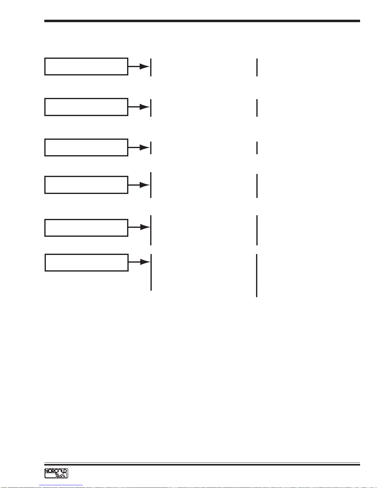
Problem Possible Cause Checks/Reference
The refrigerator does not turn ON.
The refrigerator does not cool on
AC power.
The refrigerator does not cool
efficiently on AC power.
The refrigerator does not operate
on LP gas.
The refrigerator does not
cool efficiently on LP gas.
No 12 Vdc power to refrigerator.
Faulty/loose 12 Vdc connections.
F1 fuse in power board open.
No AC power to refrigerator.
F3 fuse in power board open.
AC heater failed open.
Ventilation obstructed.
AC voltage low.
No LP gas.
Incorrect electrode-to-burner gap.
Faulty spark/sense electrode assembly.
Flame sensing circuit failure.
Ventilation obstructed.
Incorrect LP gas pressure.
Dirty burner.
Missing flue baffle.
Flue cap blocked.
See page 9.
Check 12 Vdc connections.
Check F1 fuse.
See page 13.
Check F3 fuse.
Check heaters' resistances.
Check enclosure for air flow obstructions.
Check AC voltage input.
Check LP gas supply and valves.
Set electrode to 1/8 to 3/16 in.
Replace spark/sense electrode.
Replace power board. See page 40.
Check enclosure for obstructed air flow.
Set gas pressure to 10.5 to 11.5 in. w.c.
Clean burner. See page 28.
Replace flue baffle. See page 27.
Clear flue cap. See page 27.
"No" "co" fault code.
Poor ventilation.
Off-level operation.
Dirty burner.
Low AC voltage.
Cooling fan inoperative (if present).
Improper installation.
Check enclosure for obstructed air flow.
Level unit. See page 32.
Clean burner. See page 28.
Check AC voltage input.
Test fan operation.
Check installation. See pages 19-23
and 1200 Installation Manual.
www.norcold.com/cda 1200XX/120X-IMXX ModelsRefrigerator Service Manual
5
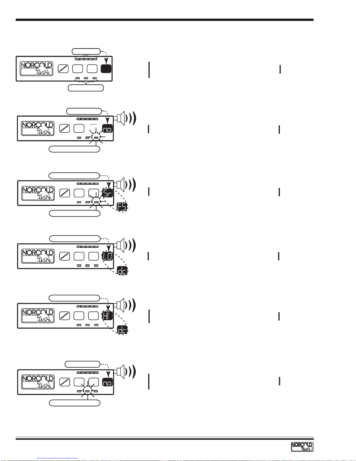
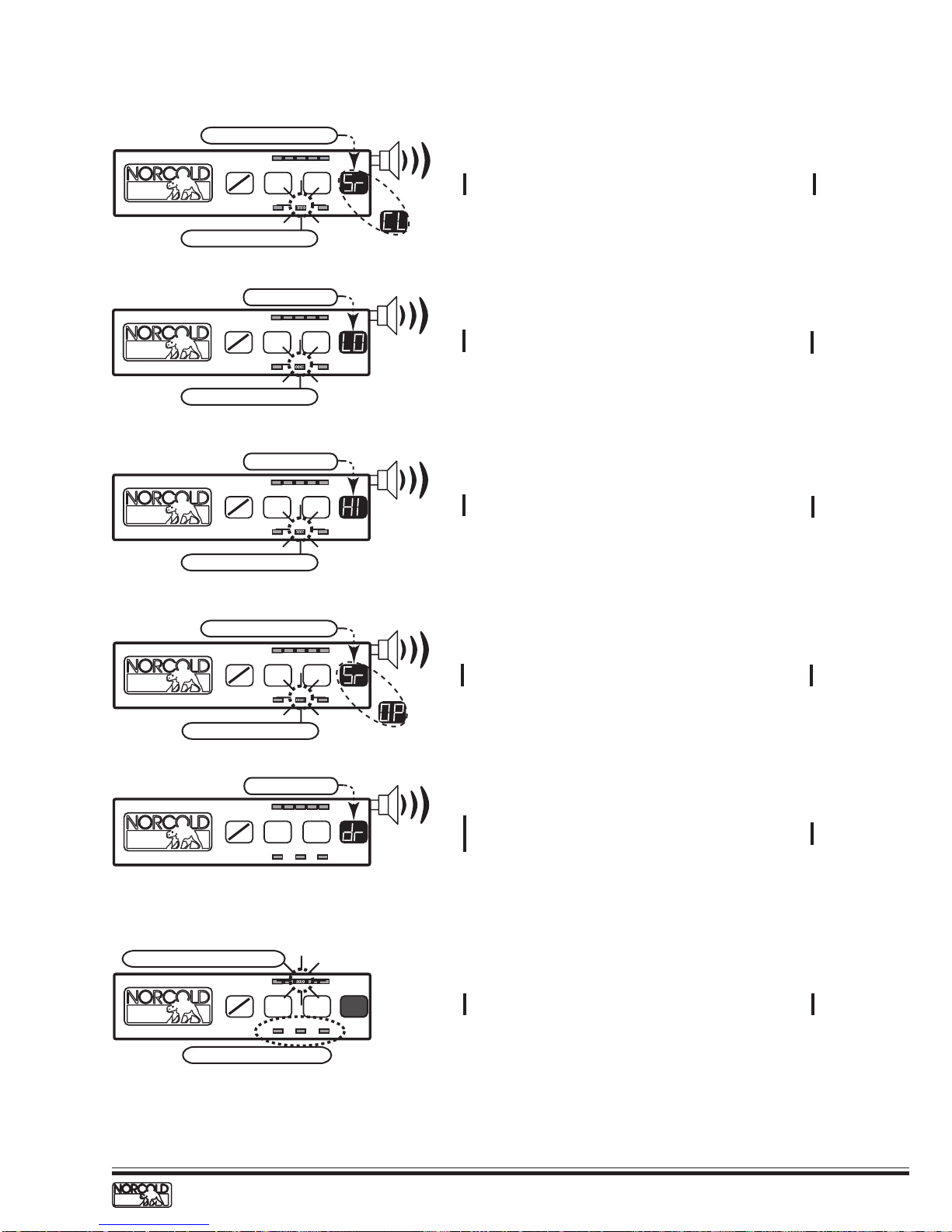
DISPLA YED FAULT CODES: S/N 832170 AND LOWER
Code
LEDs off
Cold
TEMP
ON
OFF
SET
MODE
AC LP GASAUTO
Mode LEDs off
"no" Flashing
Cold
TEMP
ON
OFF
SET
MODE
AC LP GASAUTO
"LP GAS" LED Flashing
"FS" and "Sr" Flashing
Cold
TEMP
ON
OFF
SET
MODE
AC LP GASAUTO
Coldest
Coldest
Coldest
Blank
Screen
Audible
Alarm
Audible
Alarm
Probable Cause
Refrigerator turned off.
No 12 Vdc to refrigerator
F1 fuse open.
The burner failed to ignite or reignite.
Flame sense circuit failure.
Reference
See page 9.
See page 10.
See page 11.
"LP GAS" LED Flashing
"dc" and "LO" Flashing
Cold
TEMP
ON
OFF
SET
MODE
AC LP GASAUTO
"dc" and "HI" Flashing
Cold
TEMP
ON
OFF
SET
MODE
AC LP GASAUTO
"no" Flashing
Cold
TEMP
ON
OFF
SET
MODE
AC LP GASAUTO
Coldest
Coldest
Coldest
Audible
Alarm
Audible
Alarm
Audible
Alarm
DC voltage high.
No AC power available to refrigerator.
AC cord not plugged into power board.
F3 fuse open.
See page 11.DC voltage low.
See page 12.
See page 13.
"AC" LED Flashing
6
1200XX/120X-IMXX Models
www.norcold.com/cda
Refrigerator Service Manual
Code
Probable Cause
Reference
"Sr" and "CL" Flashing
Cold
TEMP
ON
SET
OFF
AC LP GASAUTO
"AC" LED Flashing
"LO" Flashing
Cold
TEMP
ON
SET
OFF
AC LP GASAUTO
"AC" LED Flashing
"HI" Flashing
Cold
TEMP
ON
SET
OFF
AC LP GASAUTO
"AC" LED Flashing
MODE
MODE
MODE
Coldest
Coldest
Coldest
Audible
Alarm
Audible
Alarm
Audible
Alarm
AC voltage low.
AC voltage high.
See page 12.AC relay stuck closed.
See page 14.
See page 14.
"Sr" and "OP" Flashing
Cold
ON
OFF
"AC" LED Flashing
"dr" Flashing
Cold
ON
OFF
Temperature LED Flashing
Cold
ON
OFF
Selected Mode LED "ON"
TEMP
SET
Flashing "dr"
TEMP
SET
TEMP
SET
Audible
Coldest
MODE
AC LP GASAUTO
Alarm
See page 15.AC heater failed open.
Audible
Coldest
MODE
AC LP GASAUTO
Coldest
MODE
AC LP GASAUTO
Alarm
Fresh food compartment door open more than
2 minutes. Lamp switches faulty.
See page 16.
See page 17.Backup operating system in operation.
www.norcold.com/cda 1200XX/120X-IMXX ModelsRefrigerator Service Manual
7
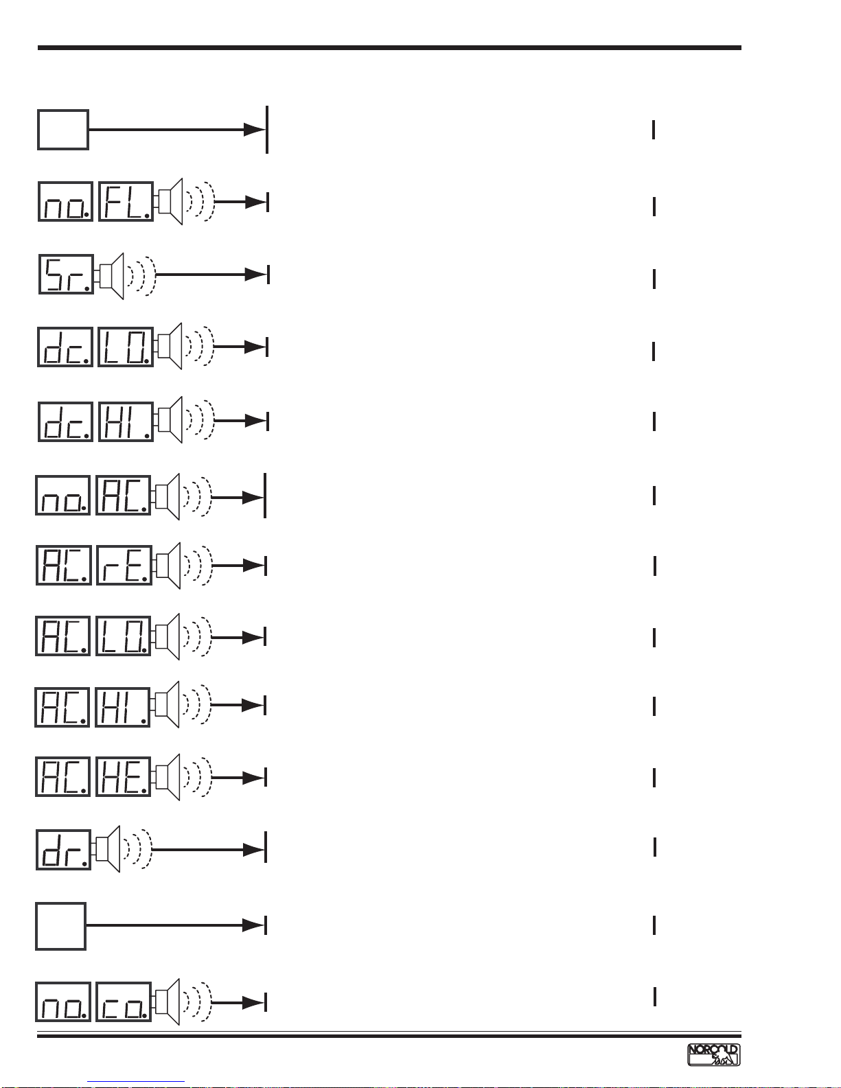
DISPLA YED FAULT CODES: S/N 832171 AND HIGHER
Code
Blank
Display
Screen
Probable Cause
Reference
Refrigerator turned off.
No 12 Vdc to refrigerator.
See page 9.
F1 fuse open.
a
t
i
n
n
r
g
e
t
l
A
y
D
a
l
i
s
p
Audible
Alarm
n
a
r
t
e
i
n
t
l
g
A
D
y
i
a
l
s
p
a
n
t
r
i
n
e
t
g
l
A
D
y
i
a
l
s
p
a
n
t
r
i
n
e
t
g
l
A
D
y
i
a
l
s
p
a
n
t
r
i
n
e
t
g
l
A
y
D
a
l
i
s
p
a
n
t
r
i
n
e
t
l
g
A
D
y
i
a
l
s
p
a
t
i
n
n
r
g
e
t
l
A
D
y
i
a
l
s
p
a
t
i
n
n
r
g
e
t
l
A
D
y
i
a
l
s
p
Audible
Alarm
Audible
Alarm
Audible
Alarm
Audible
Alarm
Audible
Alarm
Audible
Alarm
Audible
Alarm
Audible
Alarm
The burner failed to ignite or reignite.
Flame sense circuit failure.
DC voltage low.
DC voltage high.
No AC power available to refrigerator.
AC cord not plugged into power board.
F3 fuse open.
AC relay stuck closed.
AC voltage low.
AC voltage high.
AC heater failed open.
See page 10.
See page 11.
See page 11.
See page 12.
See page 13.
See page 12.
See page 14.
See page 14.
See page 15.
Audible
Fresh food compartment door open more than 2 minutes.
Lamp switches faulty.
Alarm
Flashing
Tem p
Setting
A
a
t
n
i
r
n
e
g
t
l
Audible
Backup operating system in operation.
No cooling detected by the controls.
D
y
i
a
l
s
p
8
1200XX/120X-IMXX Models
Alarm
www.norcold.com/cda
See page 16.
See page 17.
See pages 18
and 32-35.
Refrigerator Service Manual
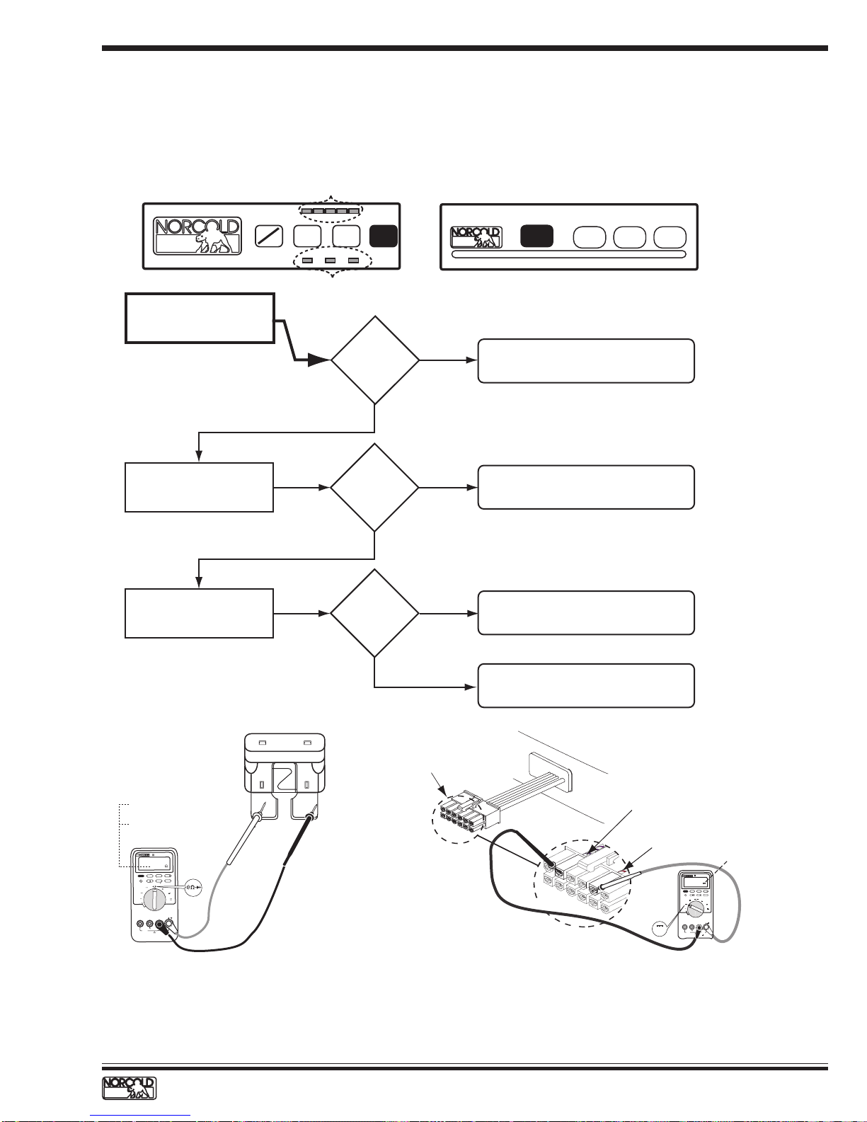
TROUBLESHOOTING FLOWCHARTS
Blank Display – Refrigerator does not turn on
Before beginning this procedure make sure:
■
The RV DC power system is supplying 10.5 to 15.4 volts to the refrigerator.
■
No other RV appliances or lighting circuits are connected to the refrigerator DC circuit.
■
12 Vdc input to the power board is wired according to the 1200XX/120X-IMXX Installation Manual.
Fault indicator displayed:
ON
Measure voltage across
power board 12VDC and
GND1 connections
.
OFF
All LEDs off
Cold
TEMP
SET
AC LP GASAUTO
Mode LED off
MODE
15.4 Vdc?
YES
Coldest
10.5
Blank
Screen
to
NO
Blank
Screen
1 COLD - 9 COLDEST SET TEMP MODE ON / OFF
on
1. No DC power input from RV to unit.
2. Faulty wiring or connectors.
Check condition of F1 fuse
in power board. See Figure 3.
Measure voltage at optical
control harness. See
Figure 4.
Good= 00.0
Ohms
Bad = OL
ETER
ULTIM
TRUE RMS M
87
III
00.0
H
HOLD
RANGE
MIN MAX
Hz
REL
PEAK MIN MAX
4 1/2 DIGITS
1 Seconds
mV
mA
A
V
A
µ
V
OFF
V
M
O
C
A
µ
A
m
A
!
400mA MAX
II
T
A
C
FUSED
1000V MAX
10A MAX
FUSED
!
F1 Fuse
F1 fuse okay?
YES
Voltage
present?
YES
Wire harness optical
control display connector
NO
NO
Replace fuse. Refer to
Specifications on page 4.
Replace power board.
See page 40.
Replace optical control assembly.
See page 41.
White/violet wire
White/red wire
V
10.5 to 15.4 Vdc
TRUE RMS MULTI METER
87
III
V
H
MIN MAX RANGE HOLD
HzREL
PEAK MIN MAX
4 1/2 DIGITS
1 Seconds
mV
mA
V
A
µA
V
OFF
V
COM
A
mA µA
!
400mA MAX
CAT II
FUSED
1000V MAX
10A MAX
!
FUSED
Figure 3. Checking the DC fuse continuity
Figure 4. Measurement points for wire harness voltage
www.norcold.com/cda 1200XX/120X-IMXX ModelsRefrigerator Service Manual
9
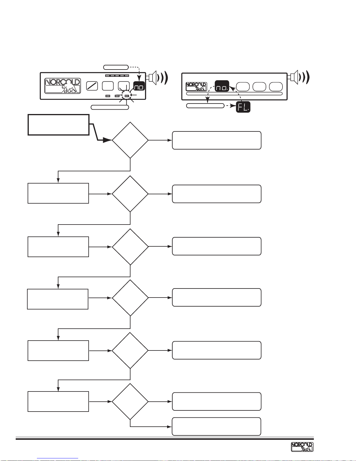
no LP - no FL Fault Code – Burner failed to ignite or reignite
Before beginning this procedure make sure:
■
RV LP gas tank valve is open.
■
Refrigerator solenoid gas valve manual shut-off is open.
■
LP gas pressure at the solenoid gas valve pressure tap is 10.5 to 11.5 in. w.c.
Fault indicator displayed:
Flashing "no"
Cold
TEMP
ON
SET
OFF
Coldest
MODE
AC LP GASAUTO
Audible
Alarm
1 COLD - 9 COLDEST SET TEMP MODE ON / OFF
on
Audible
Alarm
Check burner.
Check that electrode-toburner air gap is correct.
Check spark/sense electrode
assembly for continuity.
Blinking LP GAS LED
YES
Air gap
1/8 to 3/16
YES
Continuity?
YES
Burner
clean?
inch?
NO
NO
NO
Flashing "no" and "FL"
Clean and service burner.
See page 28.
Set electrode-to-burner air gap
1/8 to 3/16 inch.
Replace spark/sense electrode
assembly.
Check gas valve solenoid
resistance.
79 to 85 Ω?
YES
Check gas valve solenoid
wires for continuity.
Continuity?
YES
Check voltage across power
board terminals GV and
GV_GND.
YES
10
1200XX/120X-IMXX Models
NO
NO
Voltage
present?
www.norcold.com/cda
NO
Replace gas valve.
Replace gas valve wires.
Replace power board.
See page 40.
Faulty gas valve.
Replace gas valve.
Refrigerator Service Manual
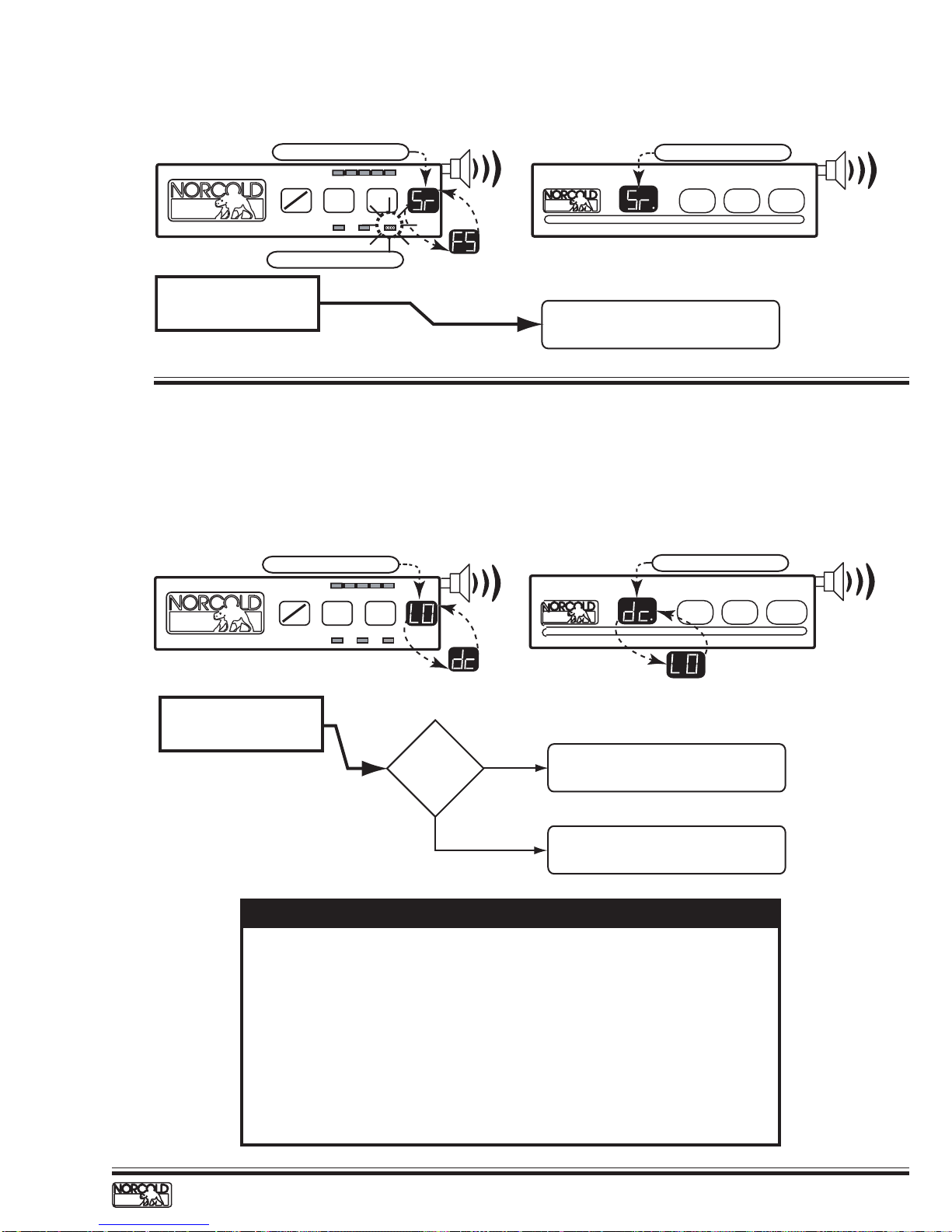
Sr FS - Sr Fault Code – Flame sense circuit failure
Fault indicator displayed:
"Sr" and "FS" Flashing
Cold
TEMP
ON
OFF
"AC" LED Flashing
SET
MODE
AC LP GASAUTO
Coldest
Audible
Alarm
"Sr" Flashing
1 COLD - 9 COLDEST SET TEMP MODE ON / OFF
on
Audible
Alarm
Flame sense circuit failure.
Replace power board.
See page 40.
dc LO Fault Code – Low dc voltage
Before beginning this procedure:
■
Make sure RV DC voltage to refrigerator is 10.5 to 15.4 volts.
■
Determine if the "dc LO" fault code displays when the converter is the source of DC power.
■
Make sure no other appliance or lighting circuit is connected to the refrigerator DC circuit.
Fault indicator displayed:
"dc" and "LO" Flashing
ON
OFF
Check for DC voltage input
to power board terminals
12VDC and GND1.
Audible
AC LP GASAUTO
MODE
Coldest
Voltage
lower than
10.5 Vdc?
Alarm
YES
1 COLD - 9 COLDEST SET TEMP MODE ON / OFF
Check RV 12 Vdc power supply to
refrigerator.
Cold
TEMP
SET
"dc" and "LO" Flashing
on
Audible
Alarm
Electronic controls operate on 12 Vdc. When an AC/DC converter is used to
supply DC power, the refrigerator circuit must be connected to the appliance
output terminals of the converter (filtered side).
If the refrigerator circuit is connected to the unfiltered side, the AC ripple
generated by the converter may cause a "dc LO" fault code to display.
T o troubleshoot a "dc LO" fault, connect a charged 12 volt automotive battery
to the power board. If the "dc LO" code clears, the fault was caused by
unfiltered DC power.
If the "dc LO" code does not clear, replace the power board (see p age 40).
NO
See NOTE below to determine
and correct low "dc LO" fault.
NOTE
www.norcold.com/cda 1200XX/120X-IMXX ModelsRefrigerator Service Manual
11
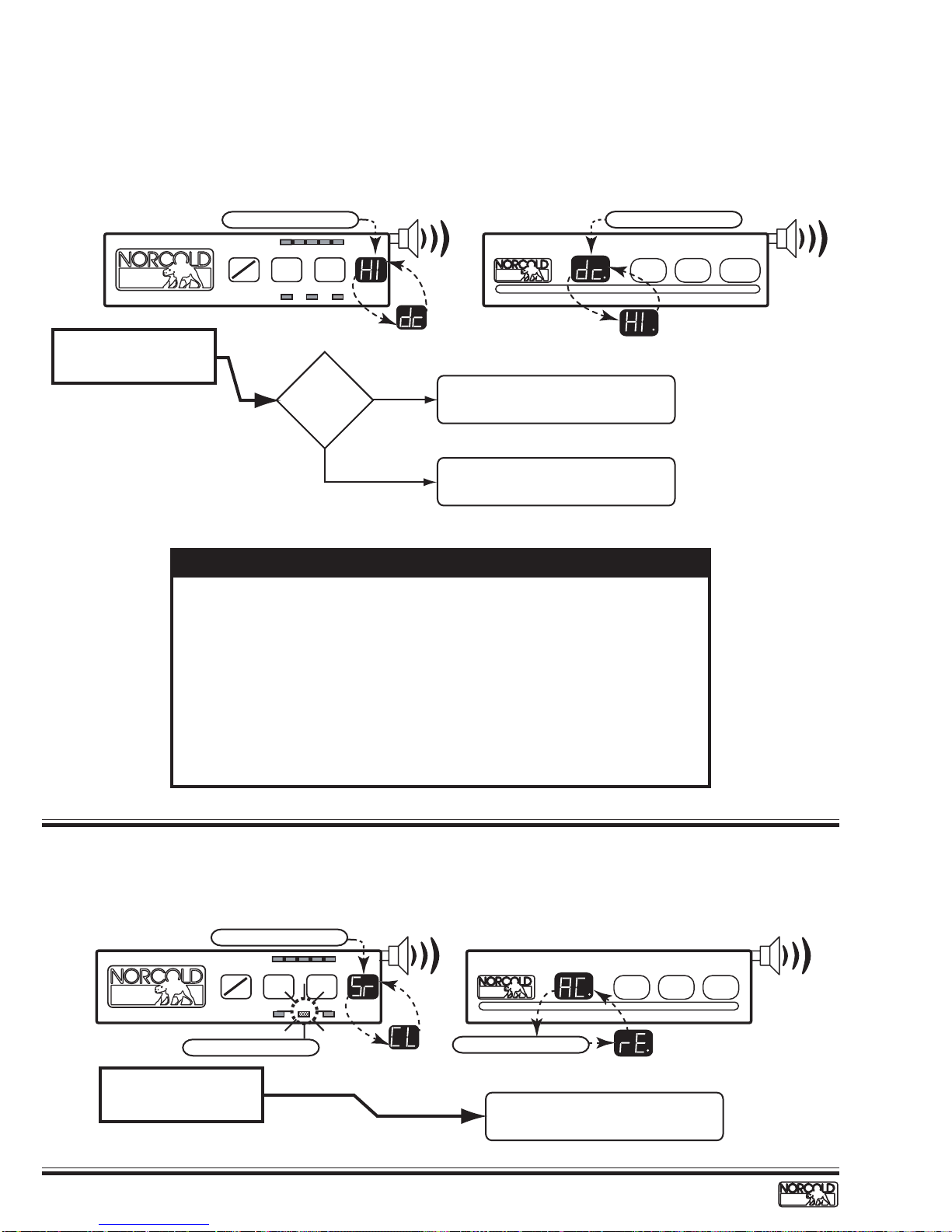
dc HI Fault Code – DC voltage high
Before beginning this procedure:
■
Make sure RV DC voltage to refrigerator is 10.5 to 15.4 volts.
■
Determine if the "dc HI" fault code displays when the converter is the source of DC power.
Fault indicator displayed:
Check for DC voltage input
to power board terminals
12VDC and GND1.
"dc" and "HI" Flashing
Cold
TEMP
ON
OFF
SET
AC LP GASAUTO
Voltage
higher than
15.4 Vdc?
MODE
Coldest
YES
Audible
Alarm
Check RV DC power distribution to
refrigerator.
1 COLD - 9 COLDEST SET TEMP MODE ON / OFF
"dc" and "HI" Flashing
on
Audible
Alarm
NO
See NOTE below to determine
and correct "dc HI" fault.
NOTE
Electronic controls operate on 12 Vdc. When an AC/DC converter is used to
supply DC power, the refrigerator circuit must be connected to the appliance
output terminals of the converter (filtered side).
If the refrigerator circuit is connected to the unfiltered side, the AC ripple
generated by the converter may cause a "dc HI" fault code to display .
T o troubleshoot a "dc HI" fault, connect a charged 12 volt automotive battery
to the power board. If the "dc HI" code clears, the fault was caused by
unfiltered DC power. If the "dc HI" code does not clear, replace the power
board (see page 40).
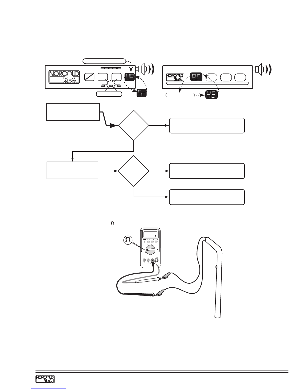
Sr CL - AC rE Fault Code – AC relay stuck closed
Fault indicator displayed:
"Sr" and "CL" Flashing
Cold
TEMP
ON
OFF
SET
MODE
AC LP GASAUTO
Coldest
Audible
Alarm
1 COLD - 9 COLDEST SET TEMP MODE ON / OFF
on
Audible
Alarm
"AC" LED Flashing
AC relay stuck closed.
12
1200XX/120X-IMXX Models
"AC" and "rE" Flashing
www.norcold.com/cda
Replace power board.
See page 40.
Refrigerator Service Manual
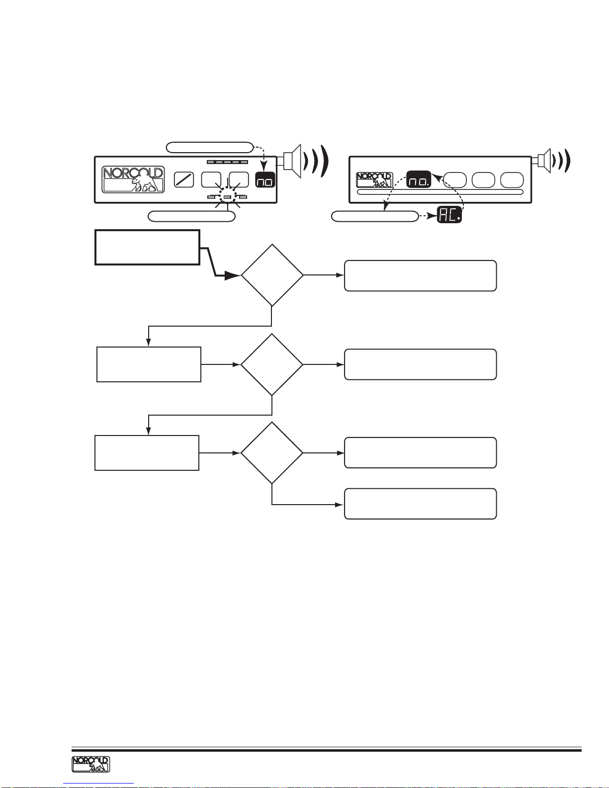
no AC Fault Code – No AC power available
Before beginning this procedure make sure:
■
No other problems exist with the RV AC power supply.
■
No other appliances or lighting circuits are connected to the refrigerator AC circuit.
■
Extension cords are not being used to supply AC power to the refrigerator.
Fault indicator displayed:
"no" Flashing
AC LP GASAUTO
MODE
Coldest
Audible
Alarm
1 COLD - 9 COLDEST SET TEMP MODE ON / OFF
Cold
TEMP
ON
OFF
SET
Audible
Alarm
on
"AC" LED Flashing
Measure voltage at power
board AC cord connection.
Check condition of F3 fuse
in power board.
Check that fuse holder clips
are making full contact with
fuse.
108
to
132 Vac?
YES
F3 fuse okay?
YES
Clips okay?
YES
"AC" and "no" Flashing
NO
NO
NO
1. Check AC power input from RV to unit.
2. Check AC power cord.
Replace fuse. See Specifications, page 4.
Adjust clips to ensure fuse contacts are
firm in clips and making full contact.
Replace power board.
See page 40.
www.norcold.com/cda 1200XX/120X-IMXX ModelsRefrigerator Service Manual
13
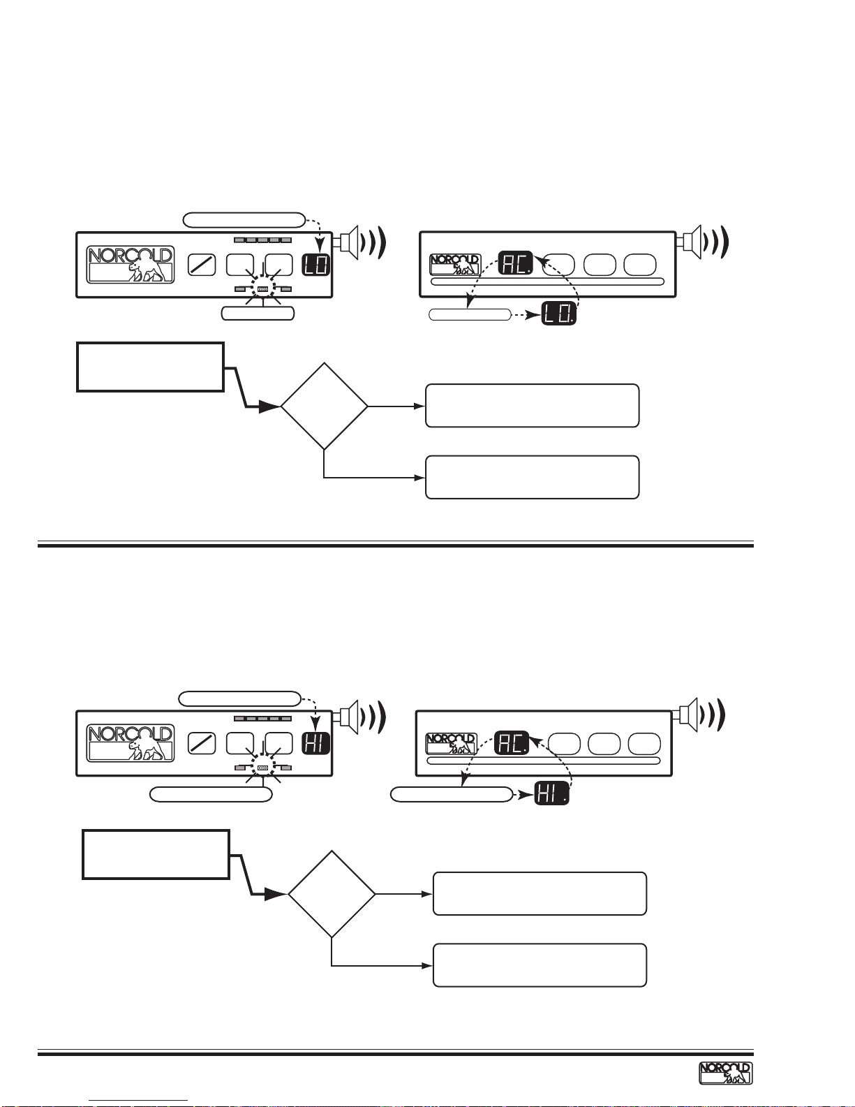
AC LO Fault Code – AC voltage low
Before beginning this procedure:
■
Determine if a certain AC power source sets the "AC LO" fault code (generator, shore power, inverter).
■
Make sure no other appliance or lighting circuit is connected to the refrigerator AC circuit.
■
Make sure extension cords are not being used to supply AC power to the refrigerator.
Fault indicator displayed:
"LO" Flashing
Cold
TEMP
ON
OFF
SET
AC LED blinking
Coldest
MODE
AC LP GASAUTO
Measure voltage at power
board AC cord connection.
Voltage
lower than
108 Vac?
AC HI Fault Code – AC voltage high
Audible
Alarm
YES
NO
1 COLD - 9 COLDEST SET TEMP MODE ON / OFF
Flashing "AC" and "LO"
on
Fault related to RV AC power distribution
component or circuit supplying AC power
to refrigerator.
Replace power board.
See page 40.
Audible
Alarm
Before beginning this procedure:
■
Determine if a certain AC power source sets the "AC HI" fault code (generator, shore power, inverter).
Fault indicator displayed:
ON
OFF
"AC" LED Flashing
Measure voltage at power
board AC cord connection.
"HI" Flashing
Cold
TEMP
SET
AC LP GASAUTO
Coldest
MODE
Voltage
higher than
132 Vac?
Audible
Alarm
"Sr" and "FS" Flashing
YES
NO
1 COLD - 9 COLDEST SET TEMP MODE ON / OFF
on
Fault related to RV AC power distribution
component or circuit supplying AC power
to refrigerator.
Replace power board.
See page 40.
Audible
Alarm
14
1200XX/120X-IMXX Models
www.norcold.com/cda
Refrigerator Service Manual
AC HE Fault Code – AC heater failed open
Before beginning this procedure make sure:
■
RV AC voltage to the refrigerator is 108 to 132 volts.
■
No other appliance or lighting circuit is connected to the refrigerator AC circuit.
Fault indicator displayed:
"OP and Sr" Flashing
ON
OFF
Check AC heater wires for
loose or damaged connection.
Check AC heater resistance.
See Figure 5.
Cold
TEMP
SET
AC LP GASAUTO
AC LED blinking
MODE
Coldest
Heater
connections
okay?
YES
Resistance
58 to 68 Ω?
YES
Audible
Alarm
NO
NO
1 COLD - 9 COLDEST SET TEMP MODE ON / OFF
on
Flashing "AC" and "HE"
Repair or replace connectors. If
connectors cannot be replaced,
replace heater.
Replace AC heater.
Replace power board.
See page 40.
Audible
Alarm
58 to 68
each heater
at room temperature
Figure 5. Checking AC heater resistance
4 1/2 DIGITS
1 Seconds
V
V
OFF
A
MIN MAX RANGE HOLD
PEAK MIN MAX
mV
mA µA
10A MAX
FUSED
H
HzREL
mA
A
µA
V
COM
!
400mA MAX
CAT II
FUSED
1000V MAX
!
L
N
O
O
C
R
Yellow
Black
www.norcold.com/cda 1200XX/120X-IMXX ModelsRefrigerator Service Manual
15
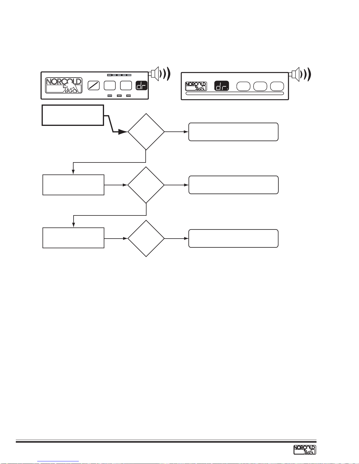
dr Fault Code – Door open for more than 2 minutes
Before beginning this procedure make sure:
■
Light/thermistor connector and wire harness connector are fully engaged and locked.
Fault indicator displayed:
Cold
ON
OFF
Check that the door latch
striker plate is adjusted
correctly.
TEMP
SET
Coldest
MODE
AC LP GASAUTO
Striker plate
okay?
YES
Audible
Alarm
NO
1 COLD - 9 COLDEST SET TEMP MODE ON / OFF
Adjust striker plate.
Audible
Alarm
on
Check fresh food
compartment door(s) for
vertical play.
Check operation of
light/door switches.
Door(s)
aligned
properly?
YES
Lights off
when switches
pressed?
NO
NO
Install Door Shim Kit, part number 625129.
Replace switch(es).
Magnetic tip screwdriver
16
1200XX/120X-IMXX Models
www.norcold.com/cda
Refrigerator Service Manual
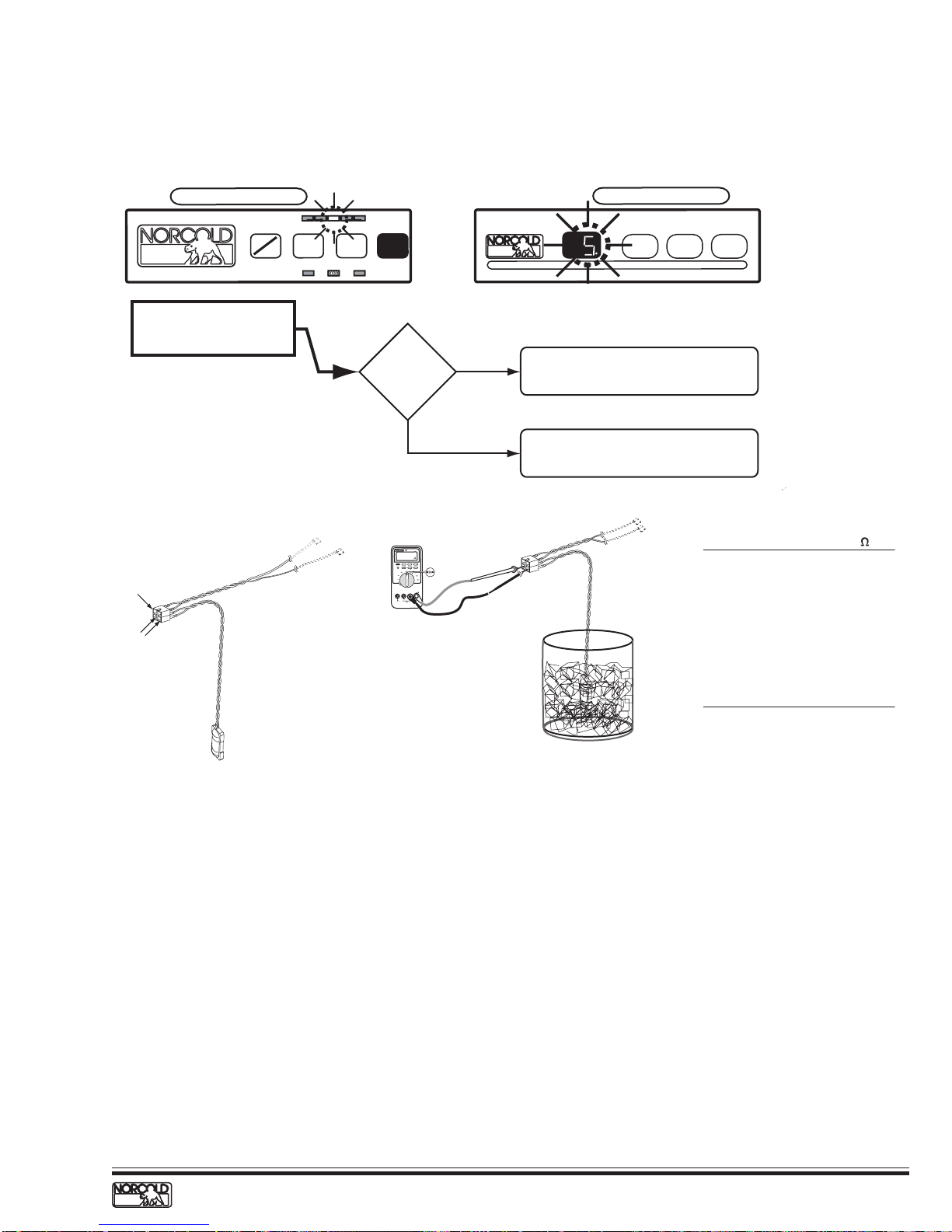
Thermistor Failure Fault – Controls in Backup Operating System mode
Before beginning this procedure:
■
Make sure lamp/thermistor assembly is connected to the wire harness.
Fault indicator displayed:
Temp Setting Flashing
ON
OFF
Check lamp/thermistor wire
assembly and connector for
dirty/broken connections.
Cold
TEMP
SET
AUTO
MODE
AC LP GAS
Coldest
Wires and
connector
good?
NO
1 COLD - 9 COLDEST SET TEMP MODE
Clean/repair terminals or connector as
required. See Figure 6.
Temp Setting Flashing
on
ON / OFF
YES
R
E
T
E
IM
T
L
U
M
S
M
R
E
RU
T
87
I
II
H
D
L
O
H
E
G
N
A
R
X
A
M
N
I
M
z
H
L
E
R
X
A
M
IN
M
K
A
E
P
S
T
I
IG
D
2
/
1
4
s
d
n
o
c
e
S
1
V
m
mA
Lamp
Connection
Thermistor
Connections
A
V
A
µ
V
FF
O
V
M
O
C
A
µ
mA
A
!
X
A
M
A
m
0
0
4
CAT II
D
E
S
U
F
X
A
M
V
0
0
0
1
X
A
M
A
0
1
D
E
S
U
F
!
Thermistor
Figure 6. Thermistor terminals
Figure 7. Checking thermistor resistance
and connector
Backup Operating System (BOS)
The backup operating system (BOS) is an
electronically controlled duty cycle. It maintains the
refrigerator in operation if the thermistor is
disconnected or fails. The BOS maintains cooling by
controlling the heat source selected. When the
refrigerator is operating in BOS, the length of the
cooling cycle is regulated by time rather than
regulated by temperature.
To accomplish this, the BOS adjusts the length of the
cooling cycle according to the temperature setting
selected by the user; the higher the temperature
setting, the longer the cooling cycle. For example, if
the temperature setting is set to 5, raising the setting
to 6 will lengthen the cooling cycle, making the
cabinet colder.
Check thermistor resistance.
See Figure 7.
Temperature* Resistance*
(oF) (k )
85 8.1– 9.0
80 9.1–10.0
75 10.1–11.0
70 11.1–12.0
60 12.1–13.0
50 15.5–16.5
40 22.5–23.5
35 24.5–25.5
33 28.5–29.5
32 30.0–32.0
*
Approximate Values
Thermistor packed in ice bath
When a warmer temperature is desired, changing the
temperature setting to a lower number shortens the
cooling cycle. For example, if the temperature setting
is set to 6, lowering the setting to 5 will shorten the
cooling cycle.
1200XX/120X-IMXX Backup Operation, SN 832170
and Lower
When the 1200XX/120X-IMXX controls shift to BOS
operation, the temperature setting flashes until the
refrigerator is no longer in BOS.
1200XX/120X-IMXX Backup Operation, SN 832171
and Higher
When the 1200XX/120X-IMXX controls shift to BOS
operation, the temperature setting flashes for ten
seconds when the TEMP button is pressed. After ten
seconds, the "ON" LED displays.
www.norcold.com/cda 1200XX/120X-IMXX ModelsRefrigerator Service Manual
17
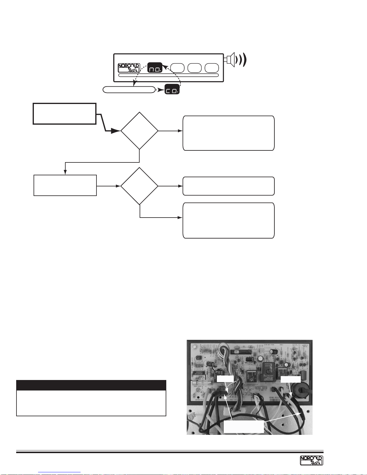
no co Fault Code* – No cooling detected by the controls - S/N 832171 and higher
Fault indicator displayed:
1 COLD - 9 COLDEST SET TEMP MODE ON / OFF
"no" and "co" Flashing
Check for cooling at fin
assembly.
Cooling
detected?
YES
Check for completion of
cooling cycle after resetting
power board.
"no" "co"
code shows
before cycle
end?
YES
* For more information on the "no co" fault code,
see pages 32-25.
on
NO
NO
Audible
Alarm
1. Check for ventilation obstructions
and leveled operation.
2. Reset power board as shown in
Figure 8 and described in procedure
below.
3. Allow unit to operate normally.
Cooling unit is good. Recheck for
ventilation obstructions and leveled
operation.
1. Replace cooling unit if "no co"
shows before completing a full
cooling cycle.
2. Reset power board as shown in
Figure 8 and described in procedure
below.
Power Board Resetting Procedure
1. Turn OFF the refrigerator .
2. Disconnect the following from power board:
a. 12 Vdc positive and negative wires.
b. AC power cord.
c. Solenoid gas valve wires.
d. Spark/sense electrode assembly wires.
3. Remove the power board cover.
4. Reconnect 12 Vdc positive and negative wire.
5. Turn ON the refrigerator .
6. Locate Pin 15 on 16 pin connector (P1). Pin
15 is the empty socket to the right of the
white/violet wire on the top row. See Figure 9.
7. Using an insulated jumper wire, short Pin 15
to the power board ground lug for 10 - 15
seconds. A click sound will indicate when the
controls are reset. See Figure 8.
NOTE
A jumper wire to short Pin 15 to ground can be made
from a six inch long insulated 22 A WG wire with a 1/2
inch of insulation stripped from each end.
10. Turn OFF the refrigerator .
1 1. Disconnect the 12 Vdc power positive and negative
wires from the power board.
12. Install the power board cover.
13. Reconnect the following to the power board:
a. Spark/sense electrode assembly wire.
b. Solenoid gas valve wires.
c. AC power cord.
d. 12 Vdc positive and negative wires from the
power board.
14. Place refrigerator in service.
Pin 15
Ground
8. Turn OFF the refrigerator .
9. Turn ON refrigerator . If "no co" code displays,
repeat steps 7 - 9.
18
1200XX/120X-IMXX Models
www.norcold.com/cda
Grounding probe
or jumper wire
Figure 8. Resetting the power board
Refrigerator Service Manual
 Loading...