

Page 1
INSTALLATION & OPERATOR’S GUIDE
MODEL 1082
FREE-STANDING
REFRIGERATOR
WARNING
Improper installation, adjustment,
alteration, service, or maintenance
can cause injury or property damage.
Refer to this manual. For assistance
or additional information consult a
qualified installer, service agency, or
the gas supplier.
FOR YOUR SAFETY
Do not store or use gasoline or other
flammable vapors and liquid in the vicinity of this or any other appliance.
Part No.: 617149 C (96 -1 0)
FOR YOUR SAFETY
If you smell gas:
1. Extinguish any open flames, pilot
lights, and all smoking material.
2. Do not touch any electrical
switches.
3. Shut off the gas supply at the tank
valve(s) or gas supply connection.
4. Open doors and other ventilating
openings.
5. Leave the area until gas odor
clears.
6. Have the gas system checked and
leakage source corrected.
Page 2
NOTICE: THIS APPLIANCE IS NOT APPROVED FOR USE IN R.V. OR MARINE APPLICATIONS.
THIS REFRIGERATOR IS EQUIPPED FOR LP GAS AND CANNOT BE CONVERTED TO
ANY OTHER FUELS (NATURAL GAS, BUTANE, ETC.).
Safety Awareness
Read this manual carefully and become thoroughly acquainted with its contents before installing and
operating the refrigerator.
Be alert to a potential Safety Hazard when the S afety Al ert Symbol appears on your refrigerator or in this
manual.
A signal word (i.e., Danger, Warning, Caution) accompanying the Safety Alert Symbol identifies the seriousness
of the Safety Hazard. Review the safety symbols and signal words below. Carefully read their descriptions to
understand their meaning. They are for your safety.
DANGER indicates the presence of a hazard that will cause severe personal injury, death, or substantial
property damage if ignored.
WARNING indicates the presence of a hazard that can cause severe personal injury, death, or substantial
property damage if ignored.
CAUTION indicates the presence of a hazard that will or can cause a minor personal injury or substantial
property damage if ignored.
WARNING
Always apply the following precautions when operating this refrigerator. Failure to heed thes e precautions
can result in substantial property damage, severe personal injury, or death.
• Carbon Monoxide can be hazardous to your to health and can result in death. A gas appliance can emit
Safety Information
excessive Carbon Monoxide gas if the refrigerator’s burner and flue system is not regularly cleaned. See pages
10 & 11 in this manual for instructions.
• Unauthorized or improper servicing of this refrigerator can cause severe personal injury, property damage, or
both. All required service and maintenance must be performed by your dealer, your propane gas supplier, or
by a Norcold authorized service center.
• This refrigerator must be used in the manner for which it was designed. Refer to this manual for installation
and operating procedures.
• Keep the refrigerator and the surrounding area clean. Never store combustible materials near the refrigerator.
Storing combustible materials near the r efrigerator not only creates a safety hazard, but als o inhibits the air
flow to the cooling system thereby reducing cooling efficiency.
• Propane gas can cause an explosion that can result in property damage, personal injury, or death. Use extreme
care when working with or near a propane gas system. Do not smoke or create sparks. Do not use an open
flame to check supply piping and fittings for leaks.
• Ground the 120 volt AC circuit in compliance with any applicable local, state, or national codes. Never cut or
remove the round grounding prong from the refrigerator’s AC power cord. Do not use a two-prong adapter. Do
not use an extension cord.
• Always replace a blown fuse with a fuse of the same ampere rating. A circuit overload can result in an electrical
fire if undersized wires or improperly sized fuses are used. To prevent a possible electrical fire, follow Norcold’s
fuse size requirements (page 5) and any applicable state and local codes.
1
Page 3
• Protect all wiring from physical damage, vibration, and excessive heat.
• Always disconnect the AC power source from the refrigerator when performing routine maintenance. All
servicing of this refrigerator must be performed by a qualified service technician.
• Keep liquids away from electrical connections. Many liquids are electrically conductive and could cause serious
arching damage and fires.
• Never bend, drop, drill, weld, manipul ate, or impact the cooling system. Doi ng so can cause the system to
rupture, releasing corrosive chemicals that can cause severe damage to the eyes and skin.
• Never attempt to repair or recharge the cooling system. A defective cooling system must be replaced by a
qualified appliance repair technician.
• After the refrigerator is in operation, do not touch the cold surfaces of the freezer, particularly with damp or wet
hands. Skin may adhere to the cold surfaces.
• To prevent child entrapment, limit access to the refrigerator and insure all wire shelves are securely fastened.
Always remove the door(s) before disposing of any refrigerator.
• This refrigerator has sharp edges and corners at the rear. Use care when working on this refri gerator. To
prevent cuts or abrasions, wear cut resistant gloves.
• Surfaces at the rear of the refrigerator are extremely hot. Contact with these surfaces can result in minor burns.
Turn the refrigerator off for several hours before attempting to move the refrigerator.
Refrigerator Specifications
LP Gas Operation - 11.0 Inches Water Column Propane
Safety Information Specifications
AC Operation - 120 Volts AC (132 Volts Max.; 108 Volts Min.); 60 Hertz Grounded Circuit
Operation where these specifications are exceeded may cause refrigerator damage and will void the refrigerator
warranty.
Introduction
You are now the owner of a Norcold Model 1082 Free-Standing Refrigerator. When used properly, this product
gives years of trouble free operation. Please read this manual c arefully; it is designed to help you keep your
refrigerator running efficiently and to answer any questions that may arise concerning your refrigerator.
Unlike a compressor driven refrigerator, the Norcold Model 1082 Refrigerator uses a gas absorption cooling
system. This cooling system uses an external energy source to heat the cooling solution, thereby evaporating the
solution and providing refrigerant circulation by means of percolation. The refrigerant travels to the freezer and
refrigerator areas, where it condenses and re-evaporates before returning to start the cycle again. This cooling
system contains no moving parts, and operates on either LP gas or AC electric input. This cooling system has
special requirements that do not apply to compressor driven refrigerators. These requirements include critical
leveling, ventilation concerns, and adequate gas an d electrical inputs, and are specifie d in later sections of t his manual.
If a problem occurs with your refrigerator, please refer to the trouble shooting section in the back of this manual.
The information provided in the trouble shooting section helps in solving minor problems.
The model and serial number of this refrigerator must be recorded. You will find these numbers on the serial tag
located in the interior of the refrigerator. These numbers should be used in any correspondence, either written or
verbal, concerning this refrigerator.
Introduction
Model: ______________________ Serial Number:_______________________
If a problem arises that is not addressed in the trouble shooting section of this manual, you will need to contact
an authorized Norcold Service Center. The service center booklet included in the information packet lists
authorized service centers in the United States and Canada.
2
Page 4
Locating and Installing the Refrigerator
Installation
This refrigerator must be installed in accordance with these Installation Instructions for the certifications and the
Norcold factory warranty to be in effect.
This appliance is design certified under the latest edition of ANSI Z21.19 Standards by the American Gas
Association and is approved by the Canadian Gas Association.
Install the refrigerator in accordance with local codes. In the absence of local codes, the installation must conform
with the following, as applicable:
In the United States:
• The National Fuel Gas Code, ANSI Z223.1.
InstallationLocation
• The manufactured Home Construction and Safety Standard, Title 24 CFR Part 3280.
When an external electrical source is utilized, the refrigerator, when installed, must be electricall y grounded in
accordance with local codes or, in the absence of local codes, the National Electrical Code, ANSI/NFPA 70.
In Canada:
• Any applicable code.
• Current Can 1-B 149.2 Installation Code for Propane Appliance and Equipment.
The refrigerator must be electrically grounded with the current Canadian Electrical Code C22.2 Parts 1 and 2.
Locating the Refrigerator
WARNING
Improper location, installation, adjustments, or unauthorized modifications can
cause injury or property damage. Refer to this manual for proper instructions.
For assistance or additional information consult a qualified install er, service
agency, or your gas supplier.
The Norcold refrigerator is to be located on a solid and
level floor that is strong enough to support the combined weight of the refrigerator and its contents. Keep
the refrigerator away from direct sunlight and other heat
generating sources.
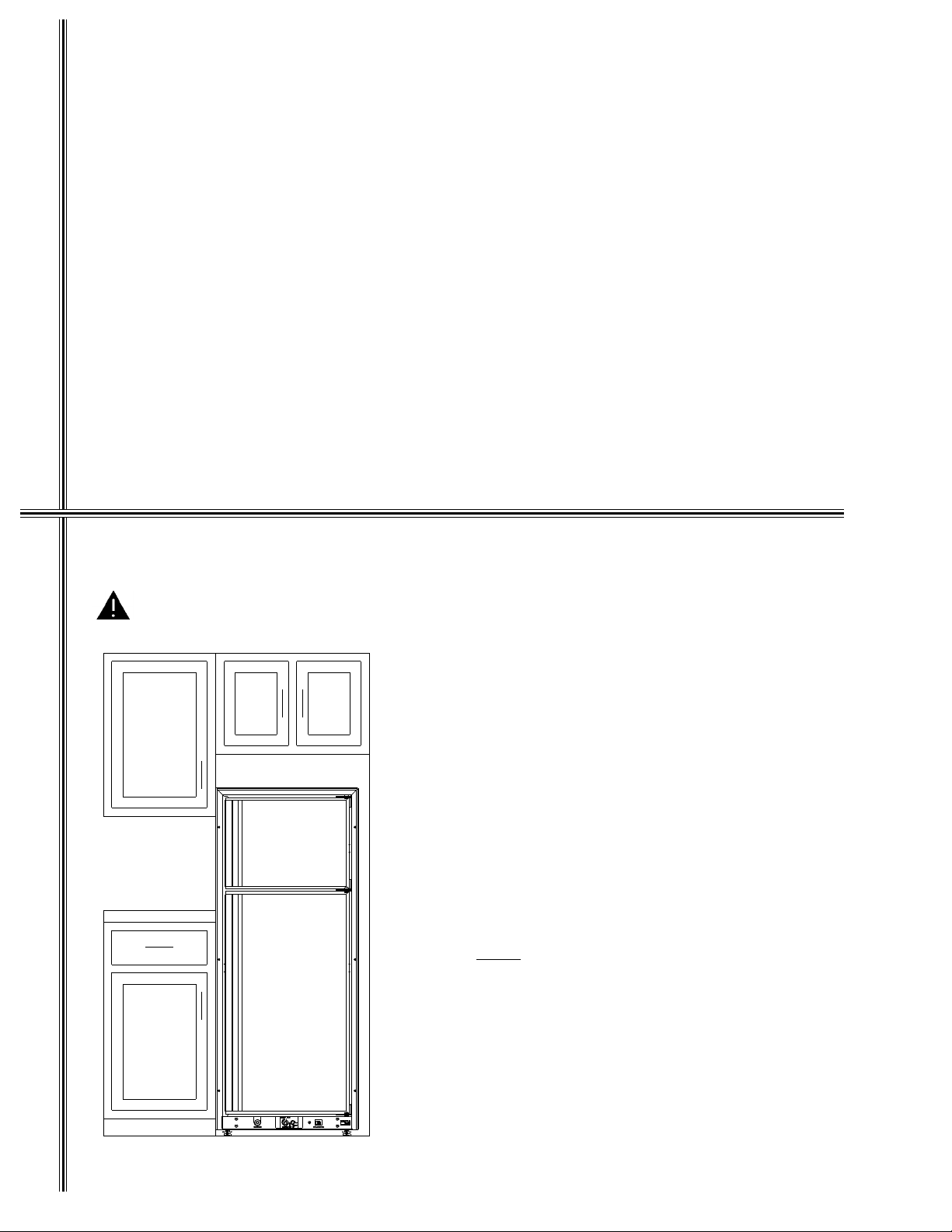
The refrigerator must be installed with the following
clearances:
Top: 6 inches minimum
Right Side: 2 inches minimum
Left Side: 0 inch minimum
Bottom: 0 inch minimum
Rear: 0 inch minimum
Do not locate the refrigerator in an area where the flow
of combustion and ventilation air is obstructed.
Notice
: Never install the refrigerator directly on carpet-
ing or vinyl floor covering. Carpeting or vinyl
flooring must be protected by a metal or wood
panel beneath the refrigerator. The panel
should extend at least the full width and depth
of the refrigerator.
Figure 1
Keep the refrigerator and the surrounding area cl ear
and free of combustible materials, gasoline, and other
flammable vapors and liquids.
3
Page 5
Leveling the Refrigerator
The refrigerator has a moisture reduction device located in the divider panel. This device will inhibit moisture from accumulating on the divider panel between
the refrigerator and freezer doors. To insure proper
operation of the refrigerator and the moisture reduction
device, the refrigerator must be level.
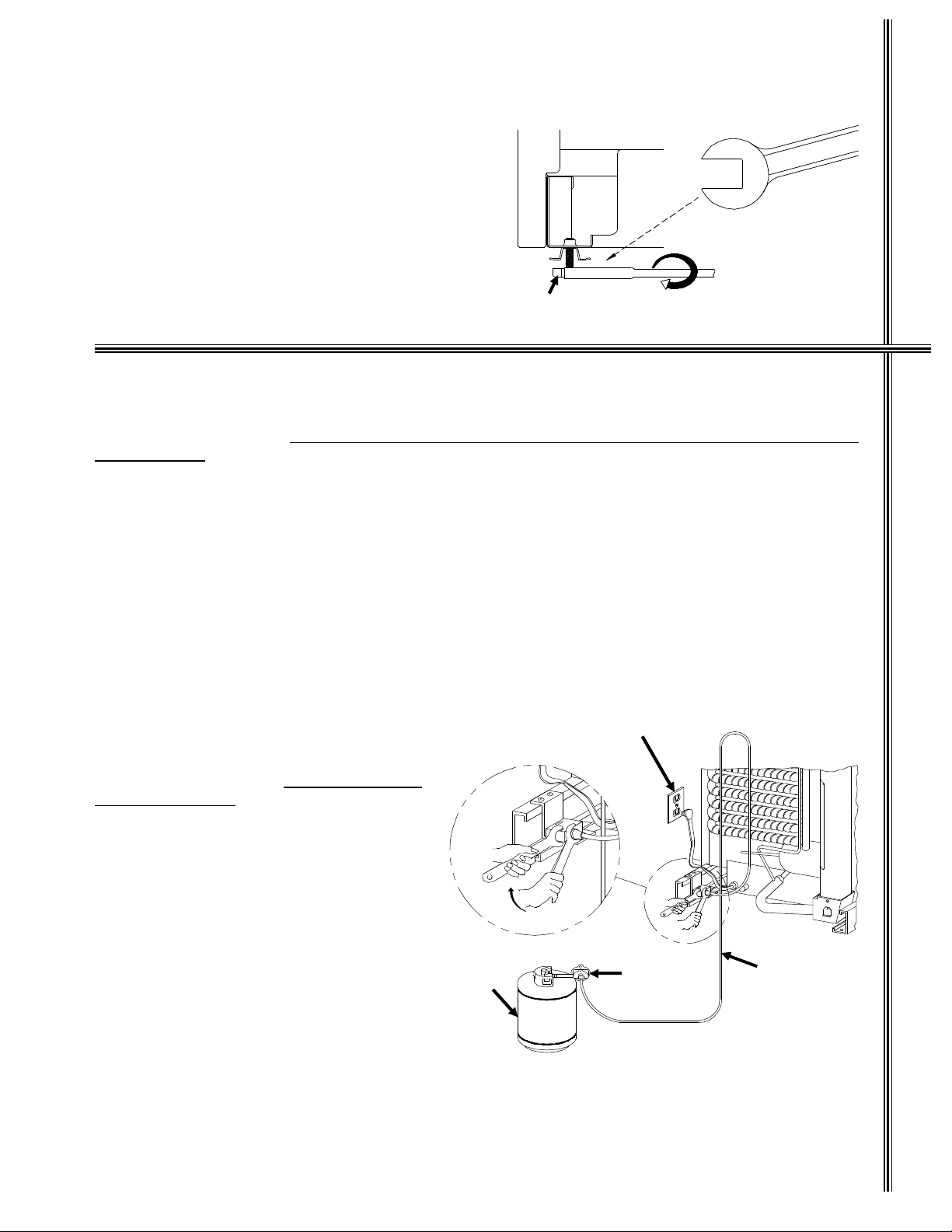
The refrigerator is equipped with leveli ng feet. Using
a bubble level placed on the floor of the freezer, adjust
the leveling feet to obtain proper leveling. To raise the
refrigerator, turn screw of leveling feet clock wise. To
lower the refrigerator, turn screw of leveling feet counterclockwise. See Figure 2.
Leveling Screw
1 3/8" Wrench
Wrench fits on head
of leveling screw.
Figure 2
Gas Connection
Install a pressure regulator between the main gas supply tank and the refrigerator to maintain the supply pressure
of 11 inches water column.
regulator in line.
Use gas supply tubing and fittings that comply with local, state, and national codes. We recommend that the gas
be supplied by 3/8 inch diameter copper piping to prevent gas pressure loss to the refrigerator. The gas connection
at the rear of the refrigerator is a 3/8 inch SAE (UNF 5/8 inch-18) male flare connection.
The gas piping should be routed to limit the possibility of damage. It is recommended that the supply piping enter
directly at the rear of the refrigerator through the floor which supports the refrigerator. The hole through which the
gas piping enters should be of sufficient size (approximately 1/2" in diameter) to provide adequate clearance. Once
the gas piping is installed, apply a sealant around the piping at its point of entry to minimize abrasion and to serve
as a barrier from external moisture.
Provide an adequate length of gas supply tubing for connecting the refrigerator to the main gas supply tank.
Additional tubing is required at the rear of the refriger ator (Figure 3) to all ow the refriger ator to be pulled s everal
feet from the wall for cleaning, maintenance, and
burner flame inspection.
To prevent gas leaks and damage to the g as
supply tubing, use two wrenches when connecting gas fittings, as illustrated in Figure 3.
The propane gas supply tubing must be inspected and tested for leaks from the refrigerator
to the main gas supply tank.
with an open flame.
piping and measurement of input gas pressure
must be performed by a qualified installer, s ervice agency, or gas supplier.
Check gas pressure to the refrigerator without
other gas appliances operating. The pressure
should not exceed 11 inches water column. With
other gas appliances operating the pressure
should not be less than 10.5 inch es water column.
The refrigerator and its individual shutoff valve
must be disconnected from the main gas supply
during testing at pressures in excess of 1/2 psig
(14 inches water column).
The refrigerator must be isolated from the gas
supply piping system by closing its individual
manual shutoff valve during any testing of the gas
supply piping system at tes t pressures equal to
or less than 1/2 psig (14 inches water column).
Testing of the gas supply
Do not connect the refrigerator directly to the main gas supply without a pressure
120 Volt AC
Receptacle
Do not test for leaks
Hold
Turn
Gas
Cylinder
Pressure
Regulator
To Refrigerator
3/8" Copper
Gas Supply Line
Figure 3
Leveling Gas Connection
4
Page 6

Gas Device Safety Test
After placing the refrigerator into operation, the gas safety device must be tested. The purpose of the gas safety
device is to prevent the escape of unburned gas from the burner if the burner flame is extinguished. While there
is a flame present at the burner, turn the refrigerator’s manual shutoff valve to "OFF". Wait 3 minutes and turn the
manual shutoff valve to "ON". Follow the Lighting Instructions ( do not push the control knob in) and try to ignite
Safety Test
the burner. The flame should not ignite. This test confirms that the safety valve is functioning properly.
Burner Flame
The efficiency of your refrigerator while operating in
the gas mode is dependent upon the correct burner
flame. The burner flame provides energy to the refrigerator’s cooling system.
The burner flame efficiency is a function of a) correct
input gas supply pressure, and, b) the burner and
burner orifice cleanliness.
After installation, the propane supply line from the
main tank to the refrigerator must be tested for leaks
All tests must be
Burner Flame InspectionAC Connection
Figure 4
and for the correct supply pressure.
performed by the propane gas supplier or a qualified
installer.
A visual inspection check of the burner flame should
be made regularly. The flame should be sharp blue with
a stable burning appearance (Figure 4). If there is a
constant yellow component observed or i f the flame
appears erratic or unstable, switch the refrigerator to
electric or turn the refrigerator "OFF", and contact a
qualified installer, service agency, or gas supplier.
120 Volts AC Connection
WARNING
3-Prong
Grounding Type
Wall Receptacle
Power Supply
Cord
This refrigerator is designed to operate on a 120 volts AC, 60 Hertz grounded
circuit. The refrigerator AC power cord is equipped with a three-prong grounding plug which must mate with a three-prong grounding receptacle to protect
against possible shock hazards. Operating the refrigerator without proper
ground can cause property damage, severe personal injury, or loss of life.
It is the owner/installer’s personal responsibility and obligation to provide a
properly grounded circuit to the refrigerator in accordance with local codes, or
in the absence of local codes , the National Electrical Code, ANSI/NFPA 70.
Do not cut or remove the grounding prong from the refrigerator’s AC power cord.
The refrigerator’s AC electrical circuit is protected by
a 5 amp fuse. The fuse is located at the rear of the
refrigerator to the right of the AC power cord.
3-Prong
Grounding
Plug
The free length of AC power cord is 72 inches. It is
recommended that the three-prong grounded receptacle be located within reach of the cord. The cord must
be routed so as not to come in contact with the burner,
flue pipe, or any other component that could cause
damage to the cord.
Figure 5
5
Page 7

Instructions for Reversing Door Swing
This refrigerator allows the owner to change the door swing if desired. The hinging of the doors can be changed
to the opposite side anytime you wish.
TOOLS REQUIRED
Phillips Screwdriver - Size #2
Two Slotted Screwdrivers
REMOVING THE DOORS
1. Turn ELEC-OFF-GAS switch, located on the control panel, to
OFF. Remove all items of food, juices, etc., from the doors.
Remove the juice rack and storage bins. Close both doors
before removing hinge pins.
2. Remove the top hinge pin using one of the slotted screwdrivers.
Remove the center hinge pin (both pieces) using the two slotted
screwdrivers; one on each end of the pin. Lastly, remove the
bottom hinge pin. Be sure to save the pins for reassembly later.
(See Figure 12)
3. Remove the upper door by opening the door slightly and pulling
the bottom of the door away from the refrigerator. Allow enough
room to slide the door down off of the upper hinge pin shoulder.
(See Figure 6)
4. Remove the lower door by opening it slightly and pulling the top
of the door away from the refrigerator. Allow enough room so
the door can be lifted up and off of the bottom hinge pin shoulder
(See Figure 7). Be sure to save the hinge plates along with the
spacer used in the middl e hinge br ack et, for r eass embly l ater.
(See Figures 12 - A, B, and C)
Figure 6
Reversing Door Swing
REMOVING AND RELOCATING THE HINGE BRACKETS
5. Remove the middle hinge bracket by using the #2 Phillips screwdriver and taking out the three screws holding
it in place. Next, remove the three sc rews on the opposite side corresponding to the c enter hinge location.
Relocate them in the holes just exposed by the removal of the hinge bracket. Attach the hinge bracket to the
refrigerator where the hole plugs previously were. Do not tighten screws completely. (See Figure 8)
6. Remove the top hinge bracket and reposition it in the opposite bottom corner. Use the same tec hnique as
outlined in Step #5.
7. Remove the bottom hinge bracket and reposition it in the opposite top corner. Use the same tec hnique as
outlined in Step #5.
Figure 7
Figure 8
6
Page 8

RELOCATING THE TRAVEL LATCHES
8. Remove both travel latches by taking out the two screws holding each to the refrigerator. Use the #2 Phillips
screwdriver. Remove the two screws from each of the corresponding holes on the opposite side of the
refrigerator. Relocate them in the two holes just exposed by the removal of the latches. Attach each latch in
the new position so the tab points towards the opposite side of the refrigerator. Do not tighten screws
completely. (See Figure 9)
9. Turn the door over so that the end previously at the bottom is now at the top. Relocate the bottom of the door
on the bottom hinge pin shoulder. Close door and align holes in top hinge brackets. The magnetic gasket will
hold the door in place. Before reinstalling the top door, check to insure that the spacer is in place. (See Figures
10 and 12 - C)
Figure 9
10. Reposition the upper door in a sim ilar ma nner as de scri bed in St ep #9, exc ept the top of the do or mus t
be engaged int o the hi nge pin sho uld er be fore s etti ng th e door in pla ce. (See Fi gur e 11)
11. Starting at the top, replace the hinge pins using the slotted screwdrivers as in the removal procedure. Tighten
all screws.
ALIGNMENT OF THE DOORS
12. Align the upper door with the lower so that there is a parallel gap between the door s and around the frame.
Adjust the doors to the cabinet so the gaskets seal but do not bind. Tighten the screws holding the hinge
brackets in place.
13. Door Seal: The door seal can be checked by closing the door on a long narrow strip of paper. A slight drag
Reversing Door Swing
should be noticed when the paper is pulled out from between the gasket and the cabinet. Repeat the process
around all four sides of the door. If the door does not seal properly, readjust the hinge brackets.
14. Position the travel latches so that they secure the doors when closed but do not prevent the doors from closing
properly. Tighten the two screws in each travel latch.
15. Replace the j uice r ack and storage bins into the door . Make sure that the mi lk bins (wi der storage bins) are
installed in the lowest door position.
A
Figure 10
B
Figure 11
C
D
Figure 12
7
Page 9

Lighting and Start Up Instructions
Lighting Instructions - Gas Operation
Hazardous Vapors. Holding the gas valve (C) in without flame ignition will
cause gas to build-up in the burner area and can result in severe personal
WARNING
injury, property damage, or death. Do not hold the gas valve in for more than
30 seconds. If the flame is not indicated within this time, turn the mode selector
knob to OFF, wait 2 minutes, and retry. If the flame still will not ignite, shut the
refrigerator off and contact a service repair technician.
Start Up Instructions
To light the refrigerator:
1. Turn on the gas supply to the refrigerator.
2. Set the thermostat (B) to it’s maximum setting.
3. Push and turn the "Elec-O ff-Gas" (C) knob counter-clockwise
to the "Gas" position.
4. Hold the control knob (C) in and push the igniter (A) repeatedly
until the gas is lit at the burner.
5. When the flame indicator (D) star ts to mov e, stop pushing the
igniter. Continue to hold the control knob in for approximately 5
seconds, then release. The flame indicator needle should remain in the green area indicating the flame is present at the
burner. If not, repeat steps 4 and 5.
The flame should ignite within 10 seconds. On initial refrigerator
Start-Up, it may take longer than 10 seconds to allow air to be
purged from the propane gas supply line.
6. Move the thermostat control (B) to desired setting.
Shutdown - All Modes
1. Push and turn the "Elec-Off-Gas" (C) control knob to the "Off"
position.
About Your Refrigerator
Figure 6
D
A
Start-Up Instructions - AC Operation
1. Make certain 110 volts AC are available to the refrigerator.
2. Set thermostat to maximum setting.
3. Push and turn "Elec-Off-Gas" control
knob clockwise to "Elec". Upon release, the knob will move outward,
indicating the control is locked into
electric operation.
C
B
THIS APPLIANCE IS DESIGNED FOR STORAGE OF FRES H FOODS, STOR AGE OF FROZ EN FOODS, AND
MAKING ICE.
Storage Volume
The model 1082 Free-Standing refrigerator provides 7.5 cubic feet of usable storage volume.
Controls
The Norcold free-standing refrigerator utilizes a single combination control to determine and regulate the mode
of operation (Gas and Electric). The control is operated by two control knobs. The first knob selects the operating
mode and the second controls the thermostat setting. The control c onsists of a gas s hut-off valve, safety valve,
thermostat, and electric interlock. The interlock prevents the poss ibility of operating on gas and electric at the
same time.
During normal operating conditions, set the thermostat at a mid-range setting. When the refrigerator or freezer
door is opened frequently or the ambient temperature is higher than 90 degrees, set the ther mostat to a colder
position.
On initial start up, it is recommended that the refrigerator be empty until the desired temperature is obtained.
Cooling to the desired operating temperature will take from eight to twelve hours, depending upon ambient
temperatures.
8
About Your Refrigerator
Page 10

Periodic Refrigerator Use
The burner , burner orifice, and the flue tu be must be inspected prior to igniting the burner f lame after extend ed
shut-down (seasona l) pe r iod s. Th ese are as m ust be fr e e fr o m du st, sp ide r w eb s, or ot he r o bst ruction s which
would restrict the flow of exhaust air, resulting in unsatisfactory refrigeration and increased carbon
monoxide emissions
(See REFRIGERATOR MAINTENANCE).
Divider Moisture Reduction Device
This refrigerator is equipped with a moi sture reduction devic e located in the divider panel. This device inhibi ts
moisture from accumulating on the divider panel between the refrigerator doors.
The Freezer Compartment
This compartment is designed to retain food in a frozen state. It is not intended for quick freezing of food.
When making ice, place the ice trays on the bottom freezer surface. Set the thermostat to its coldest setting. Do
not place packages on top of or around the ice trays while making ice.
The freezer shelf can be adjusted for different heights or can be removed to increase freezer storage capacity.
The Fresh Food Compartment
This compartment is intended to store and cool fresh foods.
Notice: Refrigeration requires air circulation within the fresh food compartment. Restriction of air circulation
will cause inadequate refrigerator temperatures and possible food spoilage. DO NOT COVER THE
REFRIGERATOR SHELVES WITH PAPER OR PLASTIC.
To control food odors, store odor emitting foods in sealed containers. Cover vegetables to retain their crispness.
To reduce frost formation on the cooling fins, cover liquids and moist foods. Do not put hot foods into the
refrigerator or let the doors remain open longer than necessary.
Allow the refrigerator to operate for a minimum of eight hours or overnight before loading the refrigerator with
About Your RefrigeratorCleaning the Interior
foods. Loading a warm refrigerator with warm foods will result in a longer refrigerator cool down period.
Door Bins
This refrigerator comes equipped with convenient door bins. These bins allow y ou to store smaller items in the
door, where they are easier to reach. These bins can be moved by simply lifting them off their attachment clips
and pushing them down over their new attachment clips. The large bins , however , need to remain in the bottom
of the door.
Crispers
The crispers located in the bottom of the refrigerator are designed to provide a higher humidity region to maintain
vegetable crispness. It is r ecommend that v egetables wi th s trong odors be wrapped so that thei r odor and taste
will not be transmitted to other stored foods.
Refrigerator Care and Cleaning
Cleaning the Interior Surfaces of the Refrigerator
Notice: Do not use abrasive cleaners to c lean the interior of the refrigerator. Abr asive cleaner s can harm
the refrigerator’s interior surfaces. Do not wash r emovable plastic door bins, shelves, etc., in an
automatic dishwasher.
It is important to keep the refrigerator interior clean to minimize food odors. The best time to clean the refrigerator
interior is after defrosting. Add a small quantity of dish detergent to lukewarm water and wash the interior.
Rinsing the interior in a solution of baking soda and water (
freshen the cabinet and neutralize odors. Wipe with a soft dry cloth to prevent water spots.
The door gaskets can be cleaned in the same manner as the refrigerator interior. After cleaning, a thi n layer of
petroleum jelly may be applied to the gaskets on the hinge side to keep the gaskets soft, thereby insuring a proper
door seal.
a tablespoon of baking soda to a quart of water
) will
9
Page 11

Cleaning the Exterior Surfaces of the Refrigerator
Clean the outer surface of the refrigerator wi th a damp sponge or c loth. Remove stubborn s tains using a mi ld
solution of soap and warm water.
The area surrounding the refrigerator, particularly at the rear, needs to be cleaned often. Cleaning prevents dust
and other foreign materials from collecting in the burner and the flue tube. Collecti on of dust, spider webs, etc.,
on the refrigerator’s condenser and absorber coils (Figure 13) restricts air circulation and results in poor refrigerator
performance. Use a soft brush to clean the absorber and condenser coils.
Procedure for Cleaning Burner, Burner Orifice, and Flue
Carbon Monoxide can be hazardous to your health and life. Gas appliances
may emit excessive Carbon Monoxide if the burner, burner orifice, and the flue
WARNING
1. Turn off gas at the main tank supply.
2. Turn the mode selection knob to the OFF position.
3. Allow the refrigerator to sit for 2-3 hours to insure the components at the rear of the refrigerator are cool before
cleaning.
4. Pull the refrigerator forward from its permanent location.
5. Unplug the refrigerator’s AC power cord.
CAUTION
tube are not regularly cleaned. To prevent Carbon Monoxide build-up, the
burner, burner orifice, and flue tube must be cleaned
after prolonged (seasonal) shut-down periods. Refer to the following cleaning
procedures, or conta ct a qualif ied insta ller, serv ice agency, or your gas sup plier.
Exercise care when servicing this refrigerator. The rear of this refrigerator is
extremely hot and has sharp edges. To prevent minor burns, turn the refrigerator off for several hours before accessing the rear of the refrigerator. Wear
cut resistant gloves to prevent cuts or abrasions while attempting to move the
refrigerator.
(Refer to Figure 13 on Page 11)
at least twice a year and
Cleaning the Flue
6. Remove the heat reflector cap from the flue.
7. Remove the spiral baffle assembly from the flue tube.
8. Using a stiff brush or fine emery cloth, clean spiral baffle of debris.
9. Clean the inside of the flue tube with a flue brush.
10. Re-install the spiral baffle.
cooling while operating in the gas mode.
Insure the baffle is securely in place. The spiral baffle is required for efficient
Cleaning the Exterior Surfaces
Cleaning the Burner and Burner Orifice
11. Remove the screws securing the burner cover and burner box to the refrigerator.
12. Review the illustration of the burner and orifice assembly (Figure 13 on page 11).
13. Loosen the gas tube connection fitting.
14. Carefully remove the gas tube from the burner.
15. Remove the orifice and orifice gasket and clean them with alcohol and air pressure.
with a pin, drill, or similar object.
16. Remove the screw securing the burner to the burner bracket. Remove the burner.
17. Use air pressure to remove du st, spider webs, etc. , from inside the burne r. Clean the ports o f the burner with a brush.
18. Clean and inspect the ignition electrode and the thermocouple. Replace if corroded.
19. Using air pressure, clean any debris from burner bracket of cooling system.
20. To reinstall, reverse the above procedures.
assembled as illustrated in Figure 13 on page 11.
Note
: If the copper gasket shows signs of wear or damage, dispose of it and contact your dealer for a
replacement.
21. Insure the burner slots are centered under the flue tube and the ignition electrode and thermocouple are
properly located (See Figure 13).
22. Leak test all fittings using a soapy water solution.
Make sure the orifice and orifice’s copper gasket are
Do not leak test fittings with an open flame.
Do not clean the orifice
10
Page 12

Condenser
Heat Deflector Cap
Flue Tube
Baffle Suspension
Wire
Absorber
Coils
Flue
Compression
Ring
Burner Box
Baffle
Burner Assembly
Orifice
Burner
Cleaning the Exterior SurfacesDoor SealsDefrosting
Connection
Fitting
Figure 13
Burner Tube
Checking Door Seals
The door gaskets must seal completely around the entire length of the door. This will insure cool ing efficiency
and prevent frost formation. Frequent frost formation or reduced cooling can be indications of air leaks.
To check for proper door seal, lay a long narrow strip of paper between the gasket and the refrigerator. Close
the door and withdraw the paper. A frictional drag should be observed. Repeat all around the doors. If the paper
does not have a noticeable drag, the gasket is not sealing. Contact your service agency for corrective procedures.
Orifice Copper
Gasket
Defrosting
After a period of operation, frost may accumulate on the freezer plate and the cooling fins, impairing cooling
efficiency. Refrigerator efficiency can be improved by periodically defrosting the refrigerator.
To defrost the refrigerator, set the "Elec-Off- Gas" control knob to "Off". E mpty the refrigerator, leav ing the drip
tray under the cooling fins and the doors open. To quicken the defrost cycle, fill a pan with hot water and place it
in the freezer. When the frost has melted, empty the drip tray and wipe it with a clean cloth. Replace the drip tray.
Replace all food and restart the refrigerator. Set the "Elec-Off-Gas" control knob to the desired mode of operation.
Set the thermostat to its maximum setting for several hours before returning it to a normal setting.
11
Page 13

Refrigerator Moving and Storage
Harmful gases. The gases in the cooling system are flammable and can be
WARNING
Before moving this refrigerator, it should be emptied, cleaned, and dried. It is imperative that the refrigerator
remain in an upright position while being moved. Failure to do so can result in a cooling system failure. Also, the
refrigerator must not be manipulated by grabbing the cooling system. This could result in a fracture of the cooling
system and the release of hazardous refrigerant.
If this refrigerator is going to be out of service for long periods of time, it should be emptied of all contents and
cleaned. Also, if possible, the doors should be left open to allow air to circulate in the refrigerator. This will prevent
the build up of odor in the refrigerator cabinet.
harmful to your health if inhaled. To prevent the release of these gases, never
place undue stresses on the cooling system. Do not manipulate the refrigerator
by grabbing the cooling system.
Moving and Storage Wiring Pictorial / Diagram
12
Page 14

Trouble Shooting
Unauthorized or improper servicing of this refrigerator can cause severe
personal injury, property damage, or both. All required service and mai nte-
must
nance
WARNING
Note: The refrigerator information packet supplied with your refrigerator includes a Norcold Service Center
location booklet.
center. Norcold will not accept respons ibility for improper instal lation, adjustment, alteration, service, or maintenance performed by anyone other than a
qualified dealer or a Norcold Service Center. Costs and consequential problems resulting from unauthorized or improper servicing of this refrigerator are
the refrigerator owner’s responsibility.
be performed by your dealer or a Norcold authorized service
Trouble Shooting
SYMPTOM
Refrigerator does not
operate in AC Mode
SYMPTOM
Refrigerator does not
operate in Gas Mode
Possible Causes
* Switch may be set to "OFF" or "GAS". See page 8
* Temperature Selector set too low. See page 8
* Refrigerator’s power cord may not be securely plugged in.
See page 5
* Circuit breaker or fuse may be tripped or blown ( AC
power source to refrigerator).
* Wall outlet may be inoperative. (This can be checked
by trying a different appliance in the same outlet.)
* If unit fails to operate after the above items have been
checked, unplug the unit and contact a service center.
Possible Causes
* Temperature Selector set too low. See page 8
* May be using gas other than LP gas.
AND CONTACT SERVICE CENTER.
* Gas not available to refrigerator (clogged gas supply
line, empty tanks, etc.). Contact gas supplier.
* Burner and orifice need cleaned. See pages 10 & 11
* Spark igniter needs replaced.
* If unit fails to operate after the above items have been
checked, unplug the unit and contact a service center.
TURN OFF GAS
SYMPTOM
Poor Performance,
Gas and Electric
Possible Causes
* Incorrect power supply. See pages 4 & 5
* Incorrect installation. See page 3
* Refrigerator off level. See page 4
* Unusually high ambient temperatures.
* Door opened frequently or for extended periods.
* Internal cabinet air circulation (wire shelves) blocked by
food items, paper, or plastic. See page 9
* Hot foods placed in refrigerator. See page 9
* Refrigerator needs defrosting. See page 11
* Temperature selector set too low. See page 8
13
Page 15

LIMITED WARRANTY
NORCOLD
P O BOX 4248
SIDNEY OH 45365-4 24 8
This Limited Warranty is given by NORCOLD ("Company") to the original consumer-purchaser of any new
refrigerating equipment ("Equipment") supplied by the Company, excluding glassware, electric light bulbs, replaceable fuses, and will be effecti ve for a period of one year from date of original purchase. The Company warrants,
provided that the Equipment shall at all times have been in possession of and used by the original consumer-purchaser, that:
A. The Company will provide free service and replacement of defective parts at no charge at all authorized
Norcold Service Centers for a period of one year from the date of original purchase. This Limited Warranty
covers labor costs incurred in removing a nd re-installing the refrigerator only when n ecessary to replace a defective
part. The Company will pay in boun d a nd ou tbou nd tra nsp ortat ion cost s of an y d efect ive pa rt, for a 1-ye ar pe riod
commencing with date of purchase. The origina l consumer-p urchaser must p ay all expenses incurred in making
the equipment available at one of the Norcold Service Centers. Any parts replaced under warranty (including
cooling units) will be warranted for the duration of the original warranty period.
B. The following procedure shall be followed by an original consumer-purchaser desiring to obtain performance
under the terms of this Limited Warranty. The refrigerator must be brought to any of the Norcold Service
Centers and the original consumer-purchaser must present evidence (1) to identify the original consumerpurchaser: and (2) that the item claimed to be defective is stil l within the warranty coverage. If the original
consumer-purchaser is unable to accomplish this task, written notice should be immediately directe d to Norcol d
and advice will be promptly given concerning the manner in wh ich warran ty service may be obtain ed. In ab lity to
physically bring the refrigerator to a Norcold Service Center will not void the warranty, but any additional costs
thereby incurred are solely for the account of the original consumer-purchaser.
C. The Company will not be liable under this Limited Warranty for any of the following:
(1) Defects which arise by reason of transit damage, misuse, neglect or accident.
(2) Manufacturing defects found at the time of purchase, or parts replaced under warranty, and associated
labor, which are not communicated to the Company within 30 days.
(3) Labor performed without need for parts replacements which is not communicated to the Company within
30 days.
(4) Defects in glassware, electric light bulbs, or replacement of fuses.
(5) Defects arising from improper installation or adjustment of the Equipment.
(6) The need for normal maintenance of this refrigerator according to the guidelines specified in the Installation
and Operating Instructions.
(7) Defects arising from the improper use of parts or parts not manufactured or supplied by the Company in
the course of repairs or replacements to the Equipment.
D. Employees and agents of the Company, and its authorized service representatives, have no authority to vary
the terms of the Limited Warranty, which applies only to Equipment purchased and i nstalled in the United
States of America and the Dominion of Canada. The Company reserves the right to make any improvements
or changes in parts or models without notice to any original consumer-purchaser.
E. The Company shall not be liable or in any way responsible for any loss or damage to person or property, or
lost profits or other similar loss or damage that may result or be claimed to have resulted from a defect in any
parts of the Equipment covered by this Limited Warranty. Some states do not allow the exclusion or limitations
of any incidental or consequential damages, so the above limitation or exclusion may not apply to you.
F. ANY IMPLIED WARRANTY OF MERCHANTABLITY OR FITNESS FOR A PARTICULAR PURPOSE:
(1) APPLICABLE TO A PART O R P ARTS OF THE REFRIGERATOR IS LIMITE D T O A PE RIOD O F ONE
YEAR FROM DATE OF PURCHASE.
(2) SOME STATES DO NOT ALLOW LIMITATIONS ON HOW LONG AN IMPLIED WARRANTY LASTS.
THE ABOVE LIMITATIONS MAY N O T APPLY TO YOU.
G. This Warranty gives you specific legal rights, and you may also have other rights which vary from state to
state.
14
 Loading...