


POS-7893
POS Motherboard
User Manual V1.0

Disclaimer
Except for the accessories attached to the product as specified herein, what is
contained in this user manual does not represent the commitments of NORCO
Company. NORCO Company reserves the right to revise this User Manual, without
prior notice, and will not be held liable for any direct, indirect, intended or unintended
losses and/or hidden dangers due to installation or improper operation.
Before ordering products, please learn about the product performance from
the distributors to see if it is in line with your needs. NORCO is a registered
trademark of Shenzhen NORCO Intelligent Technology CO.,LTD. The
ownership of other trademarks involved in this manual is owned by its
respective owners.
The contents of this manual are protected by copyright law. All rights are
strictly reserved. Any form of unauthorized reproduction including but not
limited to carbon copy, facsimile transmission and electronic copy or email is
prohibited.

Safety Instructions
1. Please read this manual carefully before using the product
2. Put all the unused or uninstalled boards or electronic components in a static dissipative
surface or static shielding bag.
3. Always ground yourself to remove any static discharge before touching the board ,
to place your hands on grounding metal object for a while or wear a grounding wrist
strap at all times.
4. When taking or fetching the boards or cards, please wear antistatic gloves and have the
habit of holding the cards by edges.
5. Make sure that your power supply is set to the correct voltage in your area. Incorrect voltage
may cause personal injuries and damage the system.
6. To prevent electronic shock hazard or any damage to the product, please ensure
that all power cables for the devices are unplugged when adding or removing
devices or reconfiguring the system.
7. To prevent electrical shock hazard, disconnect the power cable from the
electrical outlet before relocating the system.
8. When adding or removing devices to or from the system, ensure that all the
power cables for the devices are unplugged in advance.
9. To prevent any unnecessary damage to the products due to frequent power on/off, please
wait at least 30 seconds to restart the unit after the shutdown.
10. If system goes wrong during the operation, do not try to fix it by yourself. Contact
a qualified service technician or your retailer.
11. This is a Class A product, which may cause radio interference. Effective measures should
be taken against the radio interference.

Contents
Chapter 1 Product Introduction......................................................................................................1
1.1 Overview....................................................................................................................1
1.2 Specifications.............................................................................................................1
Chapter 2 Installation Instructions.................................................................................................4
2.1 Interfaces Location & Dimension..............................................................................4
2.2 Installation Steps.......................................................................................................5
2.3 Install CPU.................................................................................................................5
2.4 Install RAM................................................................................................................5
2.5 Jumper Settings.........................................................................................................6
2.5.1 CMOS Clear/Hold Jumper Setting(JCC)..................................................6
2.5.2 COM2 Jumper Setting(J1,J2,J3)...............................................................7
2.5.3 Hardware Switch for System Auto Boot upon PowerOn(JAT) .................9
2.6 Interfaces Description...............................................................................................9
2.6.1 SATA(SATA1-SATA4)................................................................................9
2.6.2 COM(COM1-COM10, J6, J9) ..................................................................10
2.6.3 Parallel Port(LPT) ....................................................................................12
2.6.4 Display(VGA1-VGA2) ..............................................................................13
2.6.5 USB(USB12, USB34, USB56)................................................................14
2.6.6 LAN(LAN).................................................................................................15
2.6.7 KBMS(PS/2) .............................................................................................16
2.6.8 FAN(CPUFAN) .........................................................................................17
2.6.9 Audio(J12, CD_IN) ...................................................................................18
2.6.10 GPIO(JGP) ............................................................................................19
2.6.11 Front Panel Connector(JFP) ..................................................................20
2.6.12 DIMM Slot(DIMM) ..................................................................................21
2.6.13 PCI Socket(PCI)....................................................................................21
2.6.14 MiNi-PCIE Socket......................................................................................22
2.6.15 Power Interface...........................................................................................22

Chapter 3 BIOS SETUP............................................................................................................23
AMI BIOS Flash.....................................................................................................23
AMI BIOS Description............................................................................................23
BIOS Settings.........................................................................................................23
3.1 Main Menu...............................................................................................................24
3.2 Advanced Menu.......................................................................................................25
3.2.1 CPU Configuration........................................................................................26
3.2.2 IDE Configuration..........................................................................................27
3.2.3 Supper IO Configuration...............................................................................28
3.2.4 Hardware Health Configuration....................................................................29
3.2.5 ACPI Configuration.......................................................................................30
3.2.6 APM Configuration........................................................................................31
3.2.7 Smbios Configuration...................................................................................33
3.2.8 USB Configuration........................................................................................34
3.2.9 Onboard LAN Option ROM Configure.........................................................36
3.3 PCI PnP Menu.........................................................................................................37
3.4 Boot Menu...............................................................................................................38
3.4.1 Boot Setting Configuration............................................................................39
3.4.2 Boot Device Priority......................................................................................40
3.4.3 Hard Disk Drives...........................................................................................40
3.5 Security Menu..........................................................................................................42
3.6 Chipset Menu..........................................................................................................44
3.6.1 North Bridge Configuration...........................................................................44
3.6.2 South Bridge Chipset Configuration.............................................................46
3.7 Exit Menu.................................................................................................................48
Appendix.......................................................................................................................................50
Appendix 1: Watchdog Programming Guide................................................................50
Appendix 2: Glossary....................................................................................................52

Chapter 1. Product
Introduction

POS-7893 High Performance POS Motherboard
1
Chapter 1 Product Introduction
1.1 Overview
POS-7893 is a type of motherboard dedicated for self-service terminals. This board adopts
Intel®G41+ICH7 chipset and supports LGA775 Intel Core2/Quad/ Extreme processor. Onboard
2*DDRIII 1066/1333 DIMM slots with each capacity up to 2GB, dual channel supported. Board
provides 4*SATA,1*Gigabit Ethernet port, 10*serial ports, 1*parallel port and 6*USB2.0 for data
communications. It also supports Line-out, Line-in, Mic-in and CD-in audio functions. Besides,
onboard 1xPCI slot and 1xMini-PCIE slot provide the system more flexible peripheral
expansion.
1.2 Specifications
Form Factor
●POS Motherboard
Dimension
●235mm×220mm(L×W)
Processor
●Support Intel Core 2 Extreme, Intel Core 2 Quad, Intel Core 2 Duo processor
●FSB: 800MHz/1066/1333MHz
Chipset
●G41+ICH7
Display
●VGA1:DB15 VGA port with resolution up to 2048×1536
●VGA2: 2×5 Pin Interface. Controller: CH7317 (SDVO to VGA). Max. Resolution upto
1920X1080
Memory
●2x 240 Pin DDR3 DIMM slots
● DDRIII 800/1066MHz RAM, single channel supports upto 2GB, dual channel supported

POS-7893 High Performance POS Motherboard
2
Storage
●4x standard Serial ATAII, transfer rate up to 300MB/s
LAN
● RTL8111D Chip
●10/100/1000 Mbps
Audio
● Realtek ALC887 audio chip
●One 4 Pin CD_IN and one 2×5 Pin Header
USB
●Three 2×5 Header USB interfaces, to coverted to 6x standard USB ports.
● Transfer rate up to 480Mb/s
I/0
●IT8783 I/O Chip
● 6x COM, COM2 :RS232/422/485
●1x double layer keyboard and mouse interface
●8bit GPIO
Expansions
●1x standard PCI port
●1x standard MiNi-PCIE port
Power Supply
●Standard ATX 20 Pin+4 Pin power supply
Watchdog
●Support system reset function
BIOS

POS-7893 High Performance POS Motherboard
3
●1MB SPI Flash BIOS
● Support ACPI power management
Environment
●Operating Temperature: 0+60℃
●Operating Humidity: 5%-95%, non-condensing

Chapter 2.
Installation
Instructions
POS-7893 High Performance POS Motherboard
4
Chapter 2 Installation Instructions
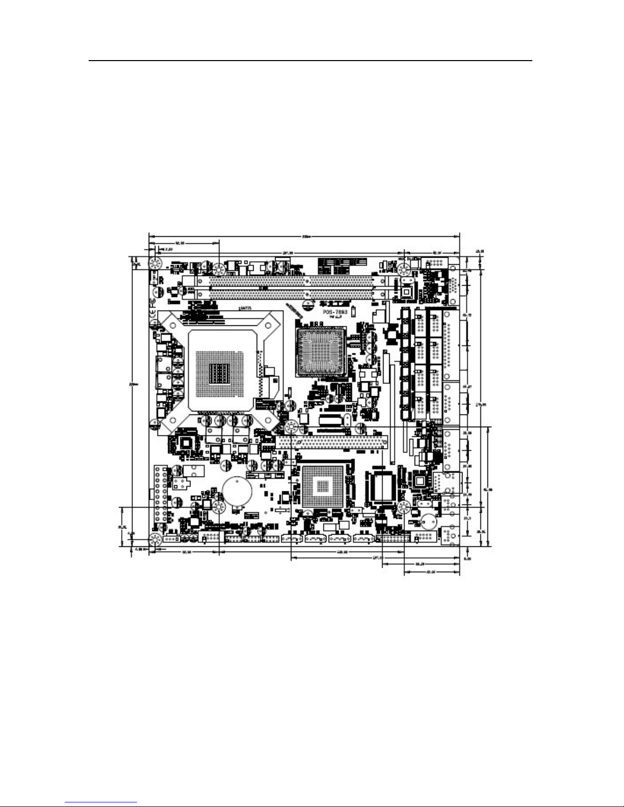
2.1 Interfaces Location & Dimension
Following picture illustrates the dimension of board POS-7893. Please pay attention to the
installation instructions. Improper installation of some components may lead to system failure.
Please note: When installing the board, please wear anti-static gloves in case of any
electostatic damage caused during the installation.

POS-7893 High Performance POS Motherboard
5
2.2 Installation Steps
Please follow the steps below to install your computer:
1. Adjust all jumpers onboard as per the user manual.
2. Install CPU
3. Install Memory
4. Install other expansion cards
5. Connect all signal lines, cables, panel control circuits and power adaptor.
6. Power on the computer and complete BIOS setup.
Key components of this motherboard are Integrated circuit, and these components
could be easily damaged by electrostatic influence. So, before installing this unit, please
always keep the following precautions in mind:
1. Hold the board by edges, don’t touch any components or plug and socket pins.
2.Wear anti-static gloves/wrist strap while touching the integrated circuit components, such as
CPU, RAM, etc.
3.Put those unused or uninstalled components in static shielding bags or trays.
4.Please first check the power switch is off before connecting the power plug.
2.3 Install CPU
Pls follow the steps below to install CPU
(1)Open the cover of CPU socket on the motherboard.
(2)Hold CPU by both sides. Make the triangle mark of its Pin1 aim at the socket notch mark
and insert CPU into the socket.
(3)Check the installation of CPU and close the socket cover.
Pls follow the steps below to install CPU FAN:
(1)Make sure the CPU FAN heat sink fits the CPU surface and fix the fan on the motherboard.
(2)Connect the fan power cord to the CPU FAN socket.
2.4 Install Memory
Board with 2x DIMM slots. Please pay attention to following two points when installing the
memory bank:
1. Please first align the notch of the RAM with the socket and press the memory bank
downward softly to tighten the connection.

POS-7893 High Performance POS Motherboard
6
2. Select a proper memory bank that matches your motherboard.
2.5 Jumper Settings
Please refer to following instructions to setup jumpers before installing your hardware devices.
Remark: How to identify the PIN1 of all jumpers and interfaces: Please observe the word mark
on the side of the plug socket, which will be a “1” or bold line or triangular symbol; And please
look at the back of PCB, each with a square shape will be the PIN 1; and all the jumpers’ PIN1
have a white arrow on the side.。
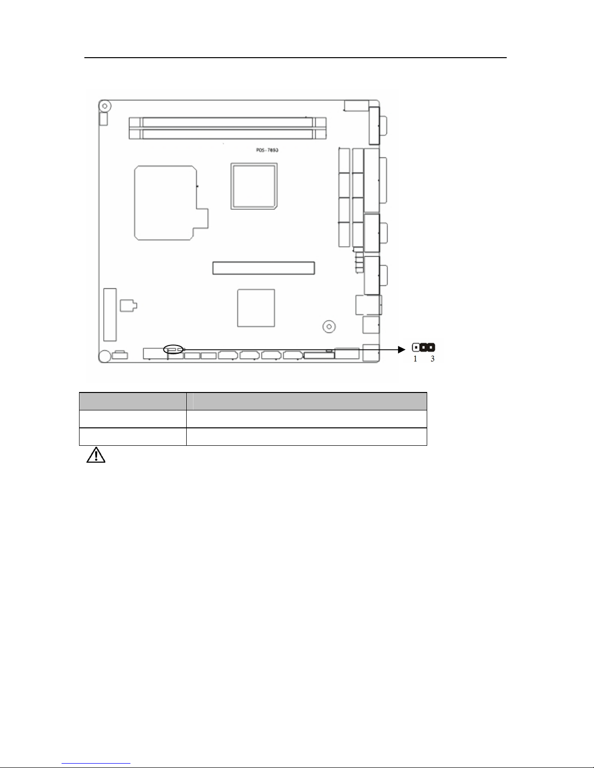
2.5.1 CMOS Clear/Hold Jumper Setting(JCC)
CMOS is powered by the onboard button cell. Clear CMOS will lead to permanent elimination
of previous system settings and back to the original system setting (factory default).
Steps。
(1)Turn off the computer and disconnect the power supply.
(2)Use Jumper Cap J36/J37 Pin1-2 short for 5~6 sec. Then restore the default setting with
Pin2-3 connected.
(3)Turn on the computer, then press “DEL” key to enter BIOS setting and reload optimal
defaults.
(4)Save and Exit
POS-7893 High Performance POS Motherboard
7
Setting JCC
1-2 Clear CMOS,BIOS back to initialization
2-3 Normal Status, System default
Do not clear CMOS when the computer is power on, otherwise, it will cause
damage to the motherboard !
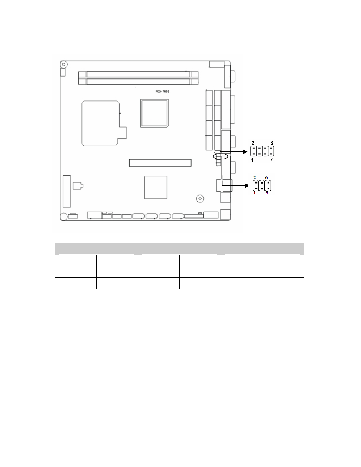
2.5.2 COM2 Jumper Setting(J1, J2, J3)
J1, J2, J3 jumpers are used to configure COM2 transmission mode. COM2 supports RS
232/RS 422/RS 48. System default setting is RS232.
POS-7893 High Performance POS Motherboard
8
COM2 RS232(Default)
COM2 RS422 COM2 RS485
J1 1-3 2-4 J1 3-5 4-6 J1 3-5 4-6
J2 1-3 2-4 J2 3-5 4-6 J2 3-5 4-6
J3 1-2 J3 3-4 J3 5-6 7-8
POS-7893 High Performance POS Motherboard
9
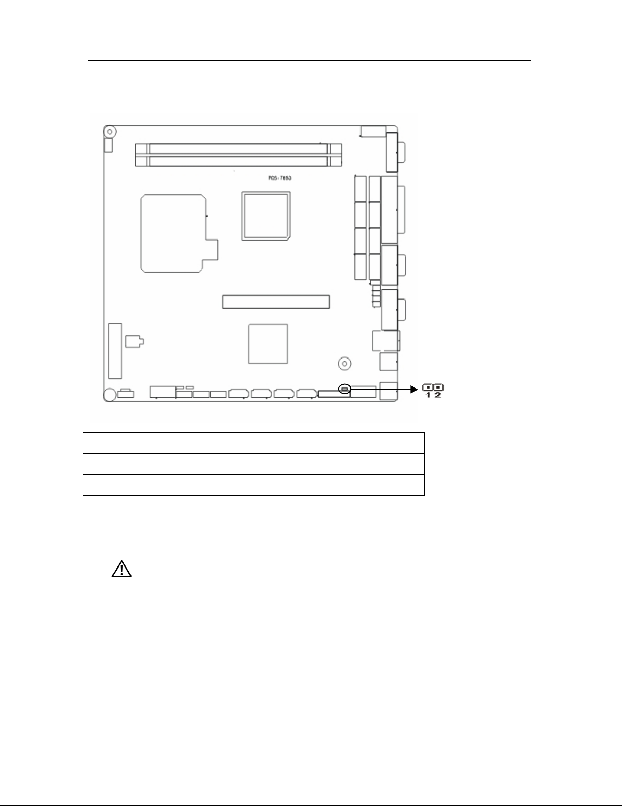
2.5.3 Hardware Switch for System Auto Boot upon Power ON(JAT)
Setting JAT
Open Non-auto boot
Close Auto boot
2.6 Interfaces Description
Please read this manual carefully before installing any external connectors, in
case of any damage to the motherboard!
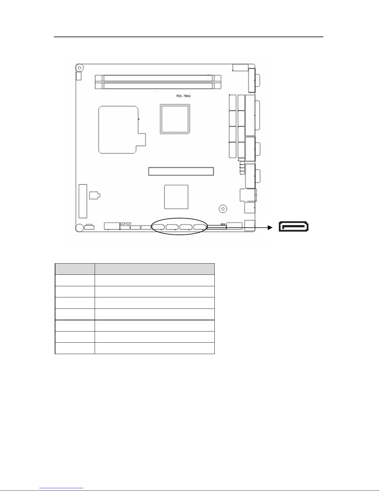
2.6.1 SATA( SATA1-SATA4)
Board provides 4x SATA port, transfer rate up to 300MB/s.
POS-7893 High Performance POS Motherboard
10
SATA:
Pin Signal Name
1 GND
2 TX+
3 TX4 GND
5 RX6 RX+
7 GND
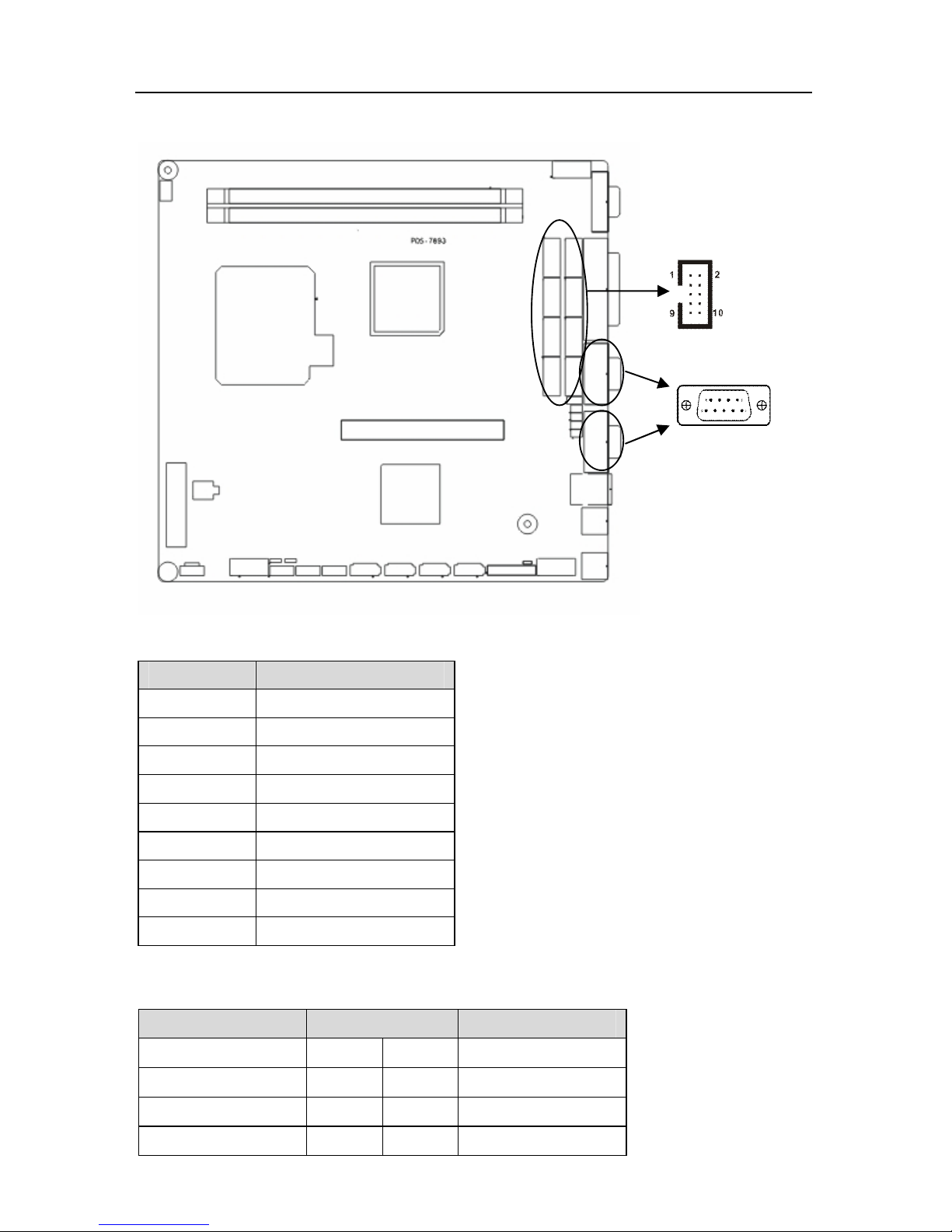
2.6.2 COM(COM1-COM10, J6, J9)
Board provides 10x COM ports. Two standard DB9 serial ports COM1-COM2.
COM3-COM10need to be converted to standard COM port with a covert cable.COM1-COM10
support RS232. COM2 also supports RS422/485. Users can select COM2 transmission mode.
Details please refer to Chapter 2-2.5.2 “COM2 Jumper Setting” .
POS-7893 High Performance POS Motherboard
11
COM1-COM2:
Pin Signal Name
1 DCD
2 RXD
3 TXD
4 DTR
5 GND
6 DSR
7 RTS
8 CTS
9 RI
COM3-COM10:
Signal Name Pin Signal Name
DCD 1 2 DSR
SIN 3 4 RTS
SOUT 5 6 CTS
DTR 7 8 RI
POS-7893 High Performance POS Motherboard
12
GND 9 10 GND
J6,J9 are used to provide power/alert mode for COM1 COM2.
Jumper Setting Function Remark
1-3 COM2 +5V
2-4 COM1 +5V
3-5 COM2 +12V
J9
4-6 COM1 +12V
1-3 COM2 VOL TAGE
2-4 COM1 VOL TAGE
3-5 COM2 RING Default
J6
4-6 COM1 RING Default
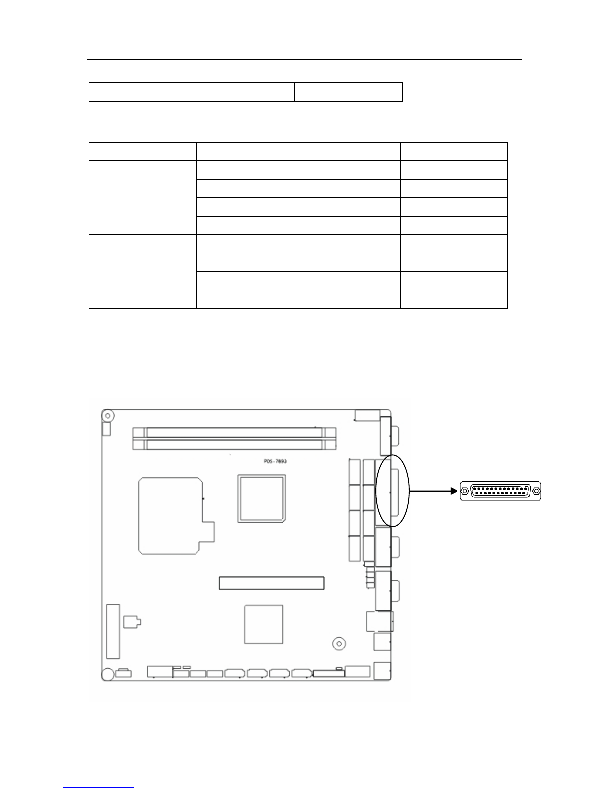
2.6.3 Parallel Port(LPT)
Standard 25 Pin parallel port to connect parallel devices.
POS-7893 High Performance POS Motherboard
13
LPT:
Signal Name Pin Signal Name
STROBE 1 2 DATA0
DATA1 3 4 DATA2
DATA3 5 6 DATA4
DATA5 7 8 DATA6
DATA7 9 10 ACK#
BUSY 11 12 PE
SELECT 13 14 AUTO FEED#
ERR# 15 16 INIT#
SLIN# 17 18 GND
GND 19 20 GND
GND 21 22 GND
GND 23 24 GND
GND 25
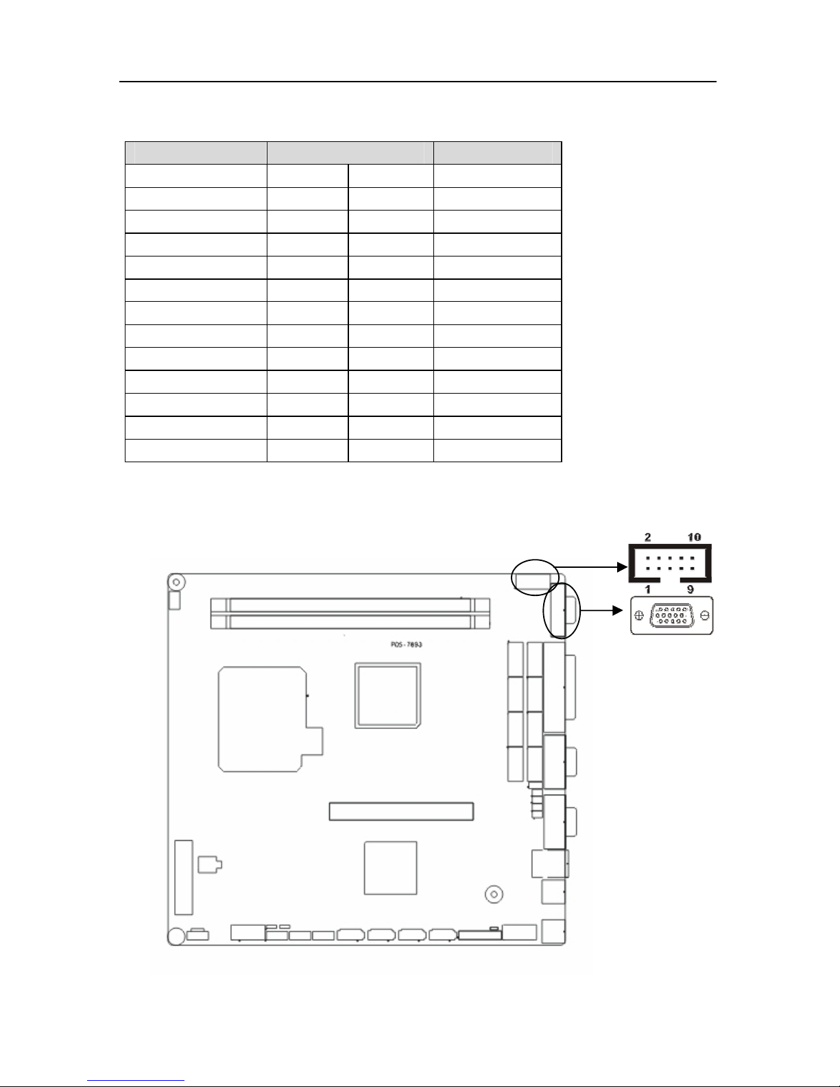
2.6.4 Display(VGA1-VGA2)
Board provides one 2×5 Pin VGA port(optional)and 1x standard DB15 VGA port.

POS-7893 High Performance POS Motherboard
14
Standard DB15 VGA:
Pin Signal Name
Pin Signal Name Pin
Signal Name
1 RED 6 GND 11
NC
2 GREEN 7 GND 12
SDA_R
3 BLUE 8 GND 13
HS_R
4 NC 9 VCC 14
VS_R
5 GND 10 GND 15
SCL_R
2×5 Pin VGA:
Signal Name Pin Signal Name
C_RED 1 2 GND
C_GREEN 3 4 5VDDC_DATA
C_BLUE 5 6 HS_R
GND 7 8 VS_R
GND 9 10 5VDDC_CLK
2.6.5 USB(USB12,USB34,USB56)
Board provides 3 group 2x 5 Pin USB interfaces, to be connected to standard USB socket with
a convert cable.

POS-7893 High Performance POS Motherboard
15
USB:
Signal Name Pin Signal Name
VCC 1 2 GND
USB DATA- 3 4 GND
USB DATA+ 5 6 USB DATA+
GND 7 8 USB DATAGND 9 10 VCC
2.6.6 LAN
Board provides 1x 10/100/1000Mbps RJ45 LAN port with one LED on each side of the
interface. The yellow one indicates data transfer status. The green one indicates network link
status.
RJ45 PORT LED Status:
LILED(GREEN) Function ACTLED(YELLOW) Function
ON Effective link Flash Data transfer

POS-7893 High Performance POS Motherboard
16
OFF Ineffective link/close
Off No data
2.6.7 KB/MS(PS/2)
PS/2 is the keyboard and mouse interface on motherboard. Users can connect the PS/2
keyboard and PS/2 mouse to the corresponding ports.(The green port is the mouse interface.
The purple one is the keyboard interface ).
PS/2 MS:
Pin Signal Name
1 MS-DATA
2 GND
3 NC
4 VCC
5 MS_CLK
6 NC
PS/2 KB:
Pin Signal Name

POS-7893 High Performance POS Motherboard
17
1 KB_DATA
2 GND
3 NC
4 VCC
5 KB_CLK
6 NC
2.6.8 CPUFAN
Board provides one 4 Pin CPUFAN interface. Please pay attention to following two points:
(1) Electric current for fan≤350mA (4.2W, 12V)
(2) Confirm the fan cable matches the fan socket
CPUFAN:
Pin Signal Name
1 GND
2 +12V
3 FANIO
4 FANPWM

POS-7893 High Performance POS Motherboard
18
2.6.9 Audio(J12, CD_IN)
Onboard audio controller, offering one 4 Pin CD_IN and one 2×5 Header.
J12:
Signal Name Pin Signal Name
MIC_L 1 2 MIC_R
SPKOUT_L 3 4 SPLOUT_R
GND 5 6 GND
GND 7 8 NC
LINE_L 9 10 LINE_R
CD_IN:
Pin Signal Name
1 CD_L
2 CD_GND
3 CD_GND

POS-7893 High Performance POS Motherboard
19
4 CD_R
2.6.10 GPIO(JGP)
GPIO: General Purpose Input/Output port. (Board provides expansion for I/O. When
microcontroller or chipset doesn’t have enough I/O, or the system needs to adopt remote serial
communications or controlling, GPIO will provide extra control and monitoring function.)
JGP:
Signal Name Pin Signal Name
GP50 1 2 VCC
GP51 3 4 GP54
GP52 5 6 GP55
GP53 7 8 GP56
GND 9 10 GP57

POS-7893 High Performance POS Motherboard
20
2.6.11 Front Panel Connector(JFP)
JFP is used to connect the function buttons and indicator LED on the front panel.
JFP:
Signal Name
Pin Signal Name
PERLED 1 2 SPK+
GND 3 4 GND
GND 5 6 GND
NC 7 8 SPKGND 9 10 GND
GND 11 12 GND
GND 13 14 PWRBTSW
NC 15 16 NC
GND 17 18 RSTBTN
HDDLED- 19 20 HDDLED+
Please follow the table below to connect, pay attention to the anode (+)and cathode(-),
otherwise , some function can not be realized.

POS-7893 High Performance POS Motherboard
21
SPEAKER
POWER LED
POWER
BUTTON
RESET
BUTTON
HDD
LED
1) System Power LED Pins (pin1, pin3 for PWLED)
Connect system power LED cable with these pins.(pin 1 is LED anode)When system power is
switched on, power LED on;when system power is switched off, power LED off.
2) Buzzer Pins (pin2, pin8 for SPEAKER)
Off board buzzer pins
3)ATX Power On/Off Button Pins (pin13, pin14 for Power Button)
Connect these two pin to the spring button on the chassis to connect or disconnect the ATX
power supply.
4)Sleep Indicator Pins(Pin 15, Pin 16 for GREEN LED)
Connect the power indicator cable to these two pins (Pin 15 is LED anode). When the system is
power on, the LED indicator will on, while the system is power off, the LED indicator will be off.
When the LED indicator is flashing, the system is sleeping.
5)IDE Device Status Indicator Pins(Pin 19,Pin20 for HDD LED)
Generally, the panel provides one IDE indicator LED. When IDE devices write or read, the LED
indicator will flash, to show the device working normally. Connect the LED indicator cable to the
pin. (Pin 19 is LED cathode).
2.6.12 DIMM Slot
Board with 2x 240 Pin DDRIII slots to support DDRIII 800/1066MHz RAM, single capacity upto
2GB.
2.6.13 PCI Socket(PCI)
Board provides one standard PCI socket.

POS-7893 High Performance POS Motherboard
22
2.6.14 MiNi-PCIE Socket
Rear panel provides one standard MiNi-PCIE Socket. J4 is the MiNi-PCIE LAN_LED port.
2.6.15 Power Interface
Standard ATX 20 Pin+4 Pin power interface.
Signal Name Pin Signal Name
+3.3V 1 11 +3.3V
+3.3V 2 12 -12V
GND 3 13 GND
+5V 4 14 PS-ON
GND 5 15 GND
+5V 6 16 GND
GND 7 17 GND
PW-OK 8 18 -5V
+5V SB 9 19 +5V
+12V 10 20 +5V
Pin Signal Name
1 GND
2 GND
3 +12V
4 +12V

Chapter 3.
BIOS SETUP

POS-7893 High Performance POS Motherboard
23
Chapter 3 BIOS SETUP
AMI BIOS Flash
BIOS functions as a bridge connecting hardware and operating system. Hardware and
software are upgrading all the time, so when your system goes wrong, for example, your
system can not support the newest CPU, you need to upgrade BIOS to keep up with the latest
technology.
AFUDOS.EXE is the FLASH IC program for BIOS to upgrade, which needs to be run in DOS
mode.
Please use a boot disk to load DOS, then run AFUDOS.EXE to upgrade BIOS( for example:
write XXXX.ROM into FLASH IC ).
Order format:
A:\ Afudos XXXX.rom
If you need to add other parameters, pls add <space>/? after the order format
Example:Afudos 7893T100.rom /P /B /C /N /X
Reminder:
1. BIOS upgrading is only executed when your system goes wrong.
2. Please use the BIOS read-write programs in the CD-ROM provided by us or download the
latest version of the upgrading program on-line
3. Please do not power off or reboot the system when upgrading, otherwise, the BIOS maybe
be damaged or system may not be able to boot again.
4. After completing the upgrading, please press <Delete> or <Del> to enter BIOS SETUP to
optimize BIOS, then press F10 to save and exit.
5. Please backup your BIOS before upgrading
AMI BIOS Description
When the computer is power on, BIOS will conduct self-diagnosis to its hardware on
motherboard and configure hardware parameter; finally the operating system will take control.
BIOS is the communication bridge between hardware and O/S. Correct configuration of BIOS
is critical for maintaining system stability and its optimized performance.
BIOS Settings
The computer starts up and system conducts self-detection, then following message pops up
on the screen :” Del->SETUP” . Press Del key and system enters BIOS SETUP interface after

POS-7893 High Performance POS Motherboard
24
finishing IDE detection.
1. Power on or reboot the computer, press <DEL> to enter into BIOS SETUP Program.
2. Use the “←↑→↓”to choose the option which your want to modify, press <Enter> and then
the sub-menu will show.
3. Use the “←↑→↓”and <Enter> to modify the value; press ”Enter” to modify BIOS options
that you choose
4. At any time, press<Esc> can go back to the father-menu.
3.1 Main Menu
AMI BIOS(Read Only)
BIOS Version: BIOS build date, BIOS ID.
System Memory(Read Only)
Display system memory size.
System Time

POS-7893 High Performance POS Motherboard
25
System Time Format: Hour/Minute/ Second.
System Date
System Date Format: Week/ Month/Day/ Year.
3.2 Advanced Menu
Note: The incorrect parameter may lead to your system failure, please set up this section
carefully according to the following instructions.

POS-7893 High Performance POS Motherboard
26
3.2.1 CPU Configuration
This Read-Only option contains the detailed information of CPU, including CPU
manufacturer, type, frequency, L1 cache and L2 cache, ect.
C1E Support
CPU C1E Function Select. Option: [Auto (default)].
Max CPUID Value Limit
[Enabled]: Support this function
[Disabled]: Disable this function.
Execute-Disable Bit Capability
Execute Disable Bit (EDB) is a hardware-based security feature that introduced to its new
generation CPU by Intel, which can help reduce system exposure to viruses and malicious
code. EDB allows the processor to classify areas in memory where application code can or
cannot execute. To use Execute Disable Bit you must have Windows XP SP2 operating system

POS-7893 High Performance POS Motherboard
27
to support this function.
Core Multi-Processing
[Enabled]: Activate multi-core CPU
[Disabled]: Single Core CPU
PECI
Enable or disable Platform Environment Control Interface.
Intel(R)Speedstep(tm)tech
Intel Speedstep Tech auto adjusts power voltage and frequency doubling to reduce power
consumption and heat dissipation, thus enhancing CPU performance. When CPU overclock,
recommend to enable this function.
3.2.2 IDE Configuration
ATA/IDE Configuration

POS-7893 High Performance POS Motherboard
28
ATA/IDE Configuration Mode Select: [Compatible] or [Enhanced].
Configure SATA as
Configure SATA as RAID,AHCI or IDE.
Primary/Secondary /Third IDE Master/Slave
These six options are used to setup IDE device type. Recommend to select [Auto] to let
system detect the IDE device by itself.
3.2.3 Supper IO Configuration
Parallel Port Address
Select parallel port address. Setting values include [Disabled], [378], [278], [3bc].
Serial Port Mode
To select serial devices types.

POS-7893 High Performance POS Motherboard
29
3.2.4 Hardware Health Configuration
Hardware Health Configuration
Hardware health detection. BIOS will display the status of the system including system
temperature, CPU temperature, CPU Fan Speed, Voltage etc.。

POS-7893 High Performance POS Motherboard
30
3.2.5 ACPI Configuration
General ACPI Configuration

POS-7893 High Performance POS Motherboard
31
Suspend mode
Select the highest ACPI sleep state the system will enter when the SUSPEND button is
pressed.
S1(CPU Stop Clock):CPU stops working while other equipments are still power up.
S3(STR): Suspend to RAM.
3.2.6 APM Configuration

POS-7893 High Performance POS Motherboard
32
RTC Power On
Enable or disable RTC to generate a wake event. When enabled. System will wake on the
hr::min::sec specified. Default setting is [Disabled].
Resume On LAN
Enable or disable system resume on LAN.

POS-7893 High Performance POS Motherboard
33
3.2.7 Smbios Configuration
Smbios Smi Support
Enable or disable SMBIOS SMI Wrapper support for PnP Function 50-54h.

POS-7893 High Performance POS Motherboard
34
3.2.8 USB Configuration
USB Devices Enabled(Read Only)
This option will display the USB devices that connected to the motherboard.
USB Function
Enable or disable USB Function.
USB2.0 Controller
[Enabled]: to enable USB2.0 port.
[Disabled]: to disable USB2.0 port.
Legacy USB Support
To enable or disable the Legacy USB support . To support USB devices in DOS mode,
such as USB FLASH disk, USB keyboard, select this option as [Enabled] or [Auto]. Otherwise,
select [Disabled].

POS-7893 High Performance POS Motherboard
35
USB2.0 Controller Mode
Setup USB 2.0 transmission mode:
<FullSpeed> : USB port is 1.1 spec (12Mbps)
<HiSpeed>: USB port is 2.0 spec (480Mbps).
Move Mouse Cursor to“USB Mass Storage Device Configuration”and press“Enter”, then
following screen pops up.
USB Mass Storage Reset Delay
Set the delay time to reset the USB devices. System defaults as [20Sec].
Emulation Type
Setup the USB flash disk emulation type when U disk boot. Emulation types include Floppy,
hard disk, CD-ROM. System defaults [Auto].

POS-7893 High Performance POS Motherboard
36
3.2.9 Onboard LAN Option ROM Configure
Onboard LAN Option ROM
Enable or disable Onboard LAN Option ROM.

POS-7893 High Performance POS Motherboard
37
3.3 PCI PnP Menu
Clear NVRAM
[NO]: Keep NVRAM
[YES]: Clear NVRAM
Plug & Play O/S
Select BIOS or PnP O/S to allocate the interrupted resource in the peripheral devices.
Choose [YES], O/S will automatically allocate the resources If O/S doesn’t have the PnP
function, please set this option as [NO].
IRQ3-15
This option is used to define the IRQ3-5 is available or reserved.

POS-7893 High Performance POS Motherboard
38
3.4 Boot Menu
Move Mouse Cursor to “ Boot Settings Configuration” and press <Enter> key, following
screen pops up:

POS-7893 High Performance POS Motherboard
39
3.4.1 Boot Setting Configuration
Quick Boot
This option allows BIOS to skip certain tests while booting. This will decrease the time
needed to boot the system.
<Enabled>: BIOS will skip 2nd and 3rd self-detection and accelerate POST
<Disabled>: After BIOS detect load Windows O/S.
Quiet Boot
[Enabled]: supplier’s LOGO will show when system starts up.
[Disabled]: Self-detect info will show when system boots.
Boot Up Num-Lock
This function allows BIOS to activate Numlock function when boot up.
[ON]:Numlock is activated when system boots up
[OFF]: Numlock under cursor control.
。

POS-7893 High Performance POS Motherboard
40
Wait For“F1”If Error
If error occurs, wait for “F1”. When the error doesn’t lead to power down, then following
messages will show: “Press ‘F1’ to resume” or “Press‘F1’ to Setup”, users can press F1 to
make the system go on working.
3.4.2 Boot Device Priority
Press “Enter” , then the following sub-menu will show:
1st Boot Device
System will detect devices by this priority until it finds an available boot device.
(Boot device can be the Removable Drive or the Hard Disk Drive).
3.4.3 Hard Disk Drives

POS-7893 High Performance POS Motherboard
41
If multi- HDD be connected, user must set up their priority. The HDD of the highest priority
will display in “Boot Device Priority”.

POS-7893 High Performance POS Motherboard
42
3.5 Security Menu
Supervisor Password
If you set up the supervisor password, it will display “Installed” .
If not, it will display “Not Installed”.
User Password
If you set up user password, it will display “Installed”.
If not, it will display “Not Installed”.
Change Supervisor Password
Press ‘Enter ‘ under this option, then enter sub-menu to change the password.
Change User Password
This option is used to change the users’ password. Press ‘Enter ‘ under this option, then
enter sub-menu to change the password.

POS-7893 High Performance POS Motherboard
43
Clear User Password
This option is for clearing users’ password. Press ‘Enter ‘under this option and select “yes”
and press “Enter” then you can clear the password.
Boot Sector Virus Protection
[Enabled]: the bootable sections protection will be available. If you execute disk
format or write the bootable section instruction, BIOS will send a warning.
Example as below:
Boot Sector Write!
Possible VIRUS: Continue (Y/N)? _
(Must press much ‘N’ and skip up)
Format!!!
Possible VIRUS: Continue (Y/N)? _
(Must press much ‘N’ and skip up )
<Disabled>: close this function.

POS-7893 High Performance POS Motherboard
44
3.6 Chipset Menu
3.6.1 North Bridge Configuration
Move Mouse Cursor to “ North Bridge Configuration” and press [Enter] key, then following
screen pops up.

POS-7893 High Performance POS Motherboard
45
Initate Graphic Adapter
Select which graphics controller to use as the primary boot device.
IGD Graphics Mode Select
Select the video memory size of the board integrated graphic cards.
It will share the video memory before installing the driver; after installing the driver, system
will allocate the memory size according to DVMT.
Move Mouse Cursor to “ Video Function Configuration” and press [Enter] key, then following
screen pops up.

POS-7893 High Performance POS Motherboard
46
DVMT Mode Select
Integrated video card DVMT Mode Select.
[DVMT]: dynamic shared video memory size. Drvier allocates the size of shared video
memoryaccording to the size of system memory.
[FIXED]: Fixed Shared Video Memory Size. Driver allocates the shared video memory
according to BIOS settings.
DVMT/FIXED Memory
Set the size of DVMT/FIXED Memory.
3.6.2 South Bridge Chipset Configuration
Move Mouse Cursor to “ SouthBridge Configuration” and press [Enter] key, then following
screen pops up:

POS-7893 High Performance POS Motherboard
47
Audio Controller
Enable or disable the onboard audio controller.
Restore on AC Power Loss
Select the computer starting up status after restoring the AC power.
[Power Off]: Press the power button to restart the computer when restore the AC power.
[Power On]: system startup directly when restore the AC Power.
[Last State]: Stay the last state before the AC power loss.
PCIE Ports Configuration
This option can be set as [Auto]/[Enabled]/[Disabled,The system defaults as [Auto].
Onboard LAN
Enable or disable the onboard LAN.

POS-7893 High Performance POS Motherboard
48
3.7 Exit Menu
Save Changes and Exit
Press [Enter] to select this option and press [Enter] to confirm to save all BIOS changes
and Exit.
Discard Changes and Exit
Press [Enter] to select this option and press [Enter] to confirm to discard all changes and
exit.
Discard Changes
Press [Enter] under this option and press [Enter] to confirm to discard all changes and still
stay at the current BIOS setup interface.
Load Optimal Defaults
Load optimal defaults, which indicate system is running at its optimum efficiency. Users are
recommended to first select this option when adjusting BIOS settings.

POS-7893 High Performance POS Motherboard
49
Load Failsafe Defaults
Load failsafe defaults. System obtains a high stability at a lower efficiency under this
setting. If system fails, this setting is very helpful.

Appendix

POS-7893 High Performance POS Motherboard
50
Appendix
Appendix 1: Watchdog Programming Guide
watchdog reference code(ASM)
--------------------------------------------------------------------------------------------------------------
Set the port to realize watchdog function through DEBUG order, so that it can carry out
Watchdog Timer’s various functions.
Port Instruction:
2EH: Address Register
2FH: Data Register
Example: Set Watchdog Timer for 30 seconds, run DEBUG command in DOS mode:
C:\>debug
-o 2e 87
-o 2e 01
-o 2e 55
-o 2e 55 : Decode
-o 2e 07 : Select Register
-o 2f 07
-o 2e 72
-o 2f c0 : set the timing unit as second (set minute: o 2f 40)
-o 2e 73
-o 2f 1e : Select time =30seconds
-q : Exit
C:\>
-----------------------------------------------------------------
Input the last line and press “enter” key, system will auto reboot within 48 seconds.
===========================================================
Reference Code (c++ language):
----------------------------------------------------------------------------------------------------
outputb (0x2e, 0x87)
outputb (0x2e, 0x87) // Unlock SUPER IO Register
outputb (0x2e, 0x2B)

POS-7893 High Performance POS Motherboard
51
outputb (0x2f, 0xE0) //bit4=0 ,set pin as watchdog function
outputb (0x2E, 0x07)
outputb (0x2F, 0x08) //select logical device
outputb (0x2e, 0x30)
outputb (0x2f, 0x01) //active the device
outputb (0x2e, 0xF5)
outputb (0x2f, 0x00) //Set timing unit as second/(set as minute: outputb (0x2f, 0x08))
outputb (0x2e, 0xF6)
outputb (0x2f, 0x30) //Set Timer Count as 30h=48 seconds
outputb (0x2E, 0xAA) //Lock SUPER IO Register
//------- code end ---------------------------------
If system halted, the watchdog enables the system to reboot automatically.

POS-7893 High Performance POS Motherboard
52
Appendix 2: Glossary
ACPI
Advanced Configuration and Power Management。ACPI specifications allow O/S to control
most power of the computer and its add-ons
BIOS
Basic input/output system. It is a kind of software including all in/out control code interface
in PC. It will do hardware testing while system is booting, and then the O/S runs. BIOS provides
a interface between O/S and hardware and is stored in a ROM chip.
BUS
In a computer system, it is the channel among different parts for exchanging data; it is also
a set of hardware lines. BUS here refers to part lines inside CPU and the main components of
system memory.
Chipset
Chipset is a Integrated set of chips for executing one or more related functions。Here it
refers to a system level chipset structured by Southbridge & Northbridge; It decides the
structure and main functions of motherboard.
CMOS
Complementary Metal-Oxide Semiconductor, which is a widely used semiconductor with
the characteristics of high-speed and low-power. COMS here refers to part of space on-board
CMOS RAM for saving date, time, system information and system parameter,ect.
COM
Computer-Output Microfilmer.A universal serial communication interface, usually adopts
normative OB 9 connector.
DIMM

POS-7893 High Performance POS Motherboard
53
Dual-Inline-Memory-Modules. It is a small circuit board with memory chipset providing 64
bit memory bus width.
DRAM
Dynamic Random Access Memorizer. It’s a normal type of memory often with a transistor
and a capacitance to store 1 bit. With the development of the technology, more and more types
of DRAM with different specifications exist in computer applications. For example:
SDRAM/DDR SDRAM/RDRAM.
I2C
Inter-Integrated Circuit , generically referred to as "two-wire interface", is a multi-master
serial single-ended computer bus invented by Philips that is used to attach low-speed
peripherals to a motherboard, embedded system, or cellphone.
LAN
Network interface. Network grouped by correlative computers in a small area, generally in
a company or a building. Local area network is buildup by sever, workstation, some
communications links. Terminals can access data and devices anywhere through cables, which
enables users to share costly devices and resource.
LED
Light-Emitting Diode. A semiconductor device that shines when power supply is connected,
It is often used to denote information directly, for example, to denote power on or HDD working
normally.
PnP
Plug-and-Play. It is a specification that allows PC to configure its external devices
automatically and can work independently without the manual operation by its user . To achieve
this function, its BIOS should be able to support PnP and a PnP expansion card
POST
Self-test when power on. While the system is booting, BIOS will do an uninterrupted
testing to the system, including RAM, keyboard, hard disk driver etc.to check if all the

POS-7893 High Performance POS Motherboard
54
components are in normal situation and work well.
PS/2
A keyboard & mouse connective interface specification developed by IBM.PS/2 is a DIN
interface with only 6PIN; it also can connect other devices, like modem
USB
It is the Universal Serial Bus for short. A hardware interface adapts to low speed
peripherals, and is always used to connect keyboard, mouse etc. One PC can connect
maximum 127 USB devices, providing 12Mbit/s transmit bandwidth USB supports hot swap
and multi- data stream, namely, you can plug USB devices while system is running, system can
auto-detect and makes it work on.

 Loading...