

Page 1

MITX-6934
Mini-ITX Motherboard
User Manual V1.0
Page 2

Disclaimer
Except for the accessories attached to the product as specified herein, what
is contained in this user manual does not represent the commitments of
NORCO Compay. NORCO Company reverves the right to revise this User
Manual,without prior notice,and will not be held liable for any
direct ,indirect,intended or unintended losses and/or hidden dangers due to
installation or improper operation.
Before ordering products, please learn about the product performance from
the distributors to see if it is in line with your needs. NORCO is a registered
trademark of Shenzhen NORCO Intelligent Technology CO.,LTD. The
ownership of other trademarks involved in this manual is owned by its
respective owners.
The contents of this manual are protected by copyright law. All rights are
strictly reserved. Any form of unauthorized reproduction including but not
limited to carbon copy, facsimile transmission and electronic copy or email is
prohibited.
Page 3

Safety Instruction
1. Please read this manual carefully before using this product.
2. Please put all unused/uninstalled boards and cards in the anti-static bags.
3. Please first place your hands on grounding metal objects for a while before you go to take
out the board from its package, so as to release the static electricity of your body.
4. Please wear antistatic gloves to take the board and have the habit of holding the board by
edges.
5. Please first check the power voltage before connecting the motherboard to power supply.
6. To prevent electric shock to human body or damage to the board, please turn off the AC
power or unplug the power cord out of power sockets before connecting or disconnecting the
mainboard or do reconfiguration.
7. Please first unplug the AC power cord out of the power socket before you move the board.
8. Before you want to plug in or unplug any equipments, please make sure all power cords are
disconnected in advance.
9. To prevent any unnecessary damage to the products due to frequent power on/off, please
wait at least 30 seconds before you restart the unit after a shutdown.
10. If any unexpected problems happened during the operation, please seek help from
professionals
11. This is a Class A product. It may cause radio interference in its working environments.In this
case, users need to take measures to prevent the interference.
Page 4

Content
Chapter 1 Product Introduction......................................................................................................1
1.1 Overview...........................................................................................................................1
1.2 Product Specification........................................................................................................1
Chapter 2 Installation Instructions.................................................................................................3
2.1 Interfaces Location and Dimension..................................................................................3
2.2 Installation Steps...............................................................................................................4
2.3 Install DIMM......................................................................................................................4
2.4 Jumper Settings................................................................................................................4
2.4.1CMOS Clear/Hold Jumper Setting(JCC) ...........................................................4
2.4.2 Hardware Switch for System Auto Boot upon Power On(JAT) ........................6
2.4.3 J_WDOG Setting...................................................................................................6
2.5 Interfaces Description.......................................................................................................7
2.5.1 SATA Interface(SATA) ......................................................................................7
2.5.2 CF Card Socket(Compact Flash).....................................................................8
2.5.3 Serial Ports(COM1, COM2_LCD) .....................................................................9
2.5.4 Display Interface(VGA) ...................................................................................10
2.5.5 USB Ports(USB12, USB34, USB56) ..............................................................10
2.5.6 Network Interface(LAN1,LAN2,LAN3,LAN4)..........................................11
2.5.7 Programmable Input/Output Interface(JGP) ..................................................12
2.5.8 Power Interface(PWR, ATX) ...........................................................................13
2.5.9 FAN Connector(SYS_FAN1, SYS_FAN2, SYS_FAN3) .................................15
2.5.10 Onboard LED and Buttons(PWR_OUT,FACTORYMOD,LED_4) ..........15
2.5.11 Front Panel Connector(JFP) .........................................................................16
2.5.12 DIMM Slot(DIMM)..........................................................................................18
2.6 LAN BYPASS Function...................................................................................................18
2.6.1 What is LAN BYPASS Function...........................................................................18
2.6.2 BYPASS Function Block Diagram.......................................................................19
2.6.3 Setup BYPASS in BIOS & WINDOWS/LINUX....................................................19
Page 5

Chapter 3 BIOS SETUP...............................................................................................................20
AMI BIOS Upgrading............................................................................................................20
AMI BIOS Description...........................................................................................................20
BIOS Settings........................................................................................................................20
3.1 Main Menu......................................................................................................................21
3.2 Advanced Menu..............................................................................................................22
3.2.1 ACPI Settings.......................................................................................................22
3.2.2 APM Configuration...............................................................................................23
3.2.3 CPU Configuration...............................................................................................24
3.2.4 SATA Configuration..............................................................................................26
3.2.5 USB Configuration................................................................................................27
3.2.6 Supper IO Configuration......................................................................................27
3.2.7 H/W Monitor..........................................................................................................28
3.2.8 Serial Port Console Redirection...........................................................................29
3.3 Chipset Menu..................................................................................................................30
3.3.1 South Bridge.........................................................................................................30
3.4 Boot Menu.......................................................................................................................31
3.5 Security Menu.................................................................................................................32
3.6 Save & Exit Menu...........................................................................................................33
Appendix......................................................................................................................................35
Appendix 1: Watchdog Programming Guide.......................................................................35
Appendix 2: IRQ & System Memory Map,1
st
MB Memory Map..........................................37
Appendix 3: Glossary............................................................................................................39
Page 6

Chapter 1 Product Introduction
Page 7

MITX-6934 Intel Cedar Trail Powered 4 Gigabit Mini-ITX Motherboard
1
Chapter 1 Product Introduction
1.1 Overview
A low profile mini-ITX board with Intel next generation Atom N2800/D2550 Processor. The
MITX-6934 is a new addition to NORCO's extensive line of thin Mini-ITX embedded boards.
Running on the the latest Intel Atom "Cedarview" processor, this network security and
communication appliance board boasts clock speeds of 1.86GHz with both single and dual
core offerings. Another great feature essential to network security appliances is the LAN
bypass feature. In the unlikely event that this device should fail, or perhaps during a power
failure, the LAN bypass feature allows data to flow through passively instead of terminating at
the device. The MITX-6934 also gives you the option to boot directly from a CF card, or from a
standard HDD or SSD drive via the SATA II port. In addition to the 2 external, and 4 internal
USB 2.0 ports, the I/O on this system includes two serial ports one via RJ45 and the other via
pin-header. This feature packed embedded board is capable of supporting 64-bit operating
systems, making it ideal for any network security or communications applications.
1.2 Product Specification
Structure Standard
● Standard Mini-ITX Motherboard
Dimension
●170mm×170mm(L×W)
Processor
●Intel Atom N2000/D2000 Series
Chipset
●Intel NM10
Display
●GPU: CPU integrated
●VGA: One 2×5Pin interface supports resolution upto 1920×1200@60Hz
Page 8

MITX-6934 Intel Cedar Trail Powered 4 Gigabit Mini-ITX Motherboard
2
Memory
●1x single channel U-DIMM slot supports DDRIII 800/1066 RAM upto 4GB.
Storage
●1x standard 7+15 Pin SATA port
LAN
●LAN Controller: 4x Intel 82583V LAN chip
●4 x standard RJ45 ports, transmission rate up to 10/100/1000Mbps
●LAN3 & LAN4 support the 3
rd
Gen Bypass(optional )
USB
● Provide 6x USB 2.0 ports
●2x standard USB 2.0 .Two 2×5Pin USB 2.0, able to be converted to 4x standard USB 2.0
I/0
●Adopt W83627DHG-P I/O chip
●2x serial ports. COM1 is the RJ45 interface. COM2_LCD is the 2×5Pin interface. COM2
supports RS232 mode.
Power Supply
●DC +12V / ATX
Watchdog
●Trigger system reset when the timer overflows.
BIOS
●2MB SPI BIOS
Environment
●Operating Temp: 0℃~50℃
●Storage Temp: -40℃ ~ 80℃
●Operating Humidity: 5% ~ 95% relative humidity, non-condensing.
Page 9

Chapter 2 Installation Instructions
Page 10
MITX-6934 Intel Cedar Trail Powered 4 Gigabit Mini-ITX Motherboard
3
Chapter 2 Installation Instructions
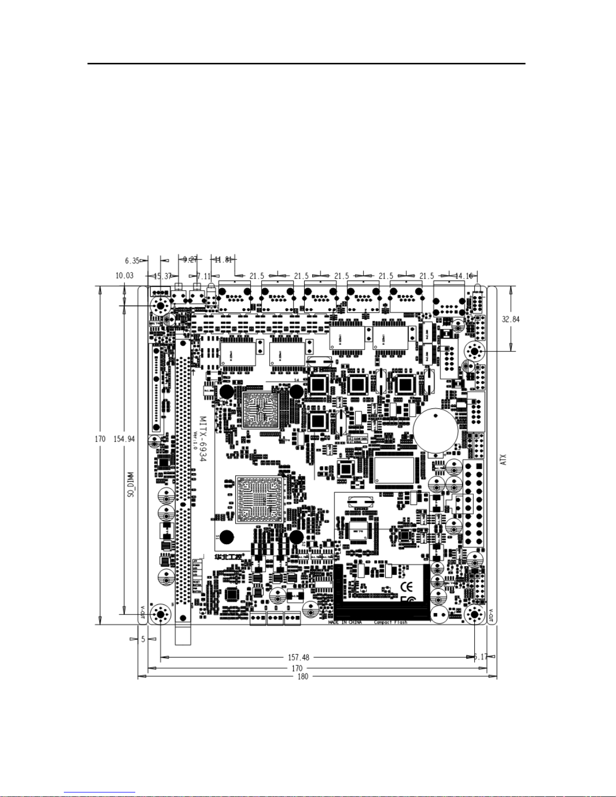
2.1 Interfaces Location & Dimension
The following picture shows the front panel interfaces location and the dimension of board
MITX-6934. Please pay attention to the installation procedures. Improper installation of any
components will lead to system malfunction.
Note: Please ware anti-static gloves to install the board, so as to avoid static electricity
causing any damage to the board.
MITX-6934 Interfaces Location & Dimension
Page 11

MITX-6934 Intel Cedar Trail Powered 4 Gigabit Mini-ITX Motherboard
4
2.2 Intallation Steps
Please follow the steps below to install your computer
1. Adjust all jumpers onboard according to the user manual
2. Install DIMM
3. Install other expansion cards
4. Connect all signal cables, power cable, panel control circuit and power adaptor
5.Start the computer and finish BIOS settings.
Key components of this motherboard are Integrated circuit, and these components
could be easily damaged by electrostatic influence. So, before installing this unit, please
always keep the following precautions in mind:
1. Hold the board by edges, don’t touch any components or plug and socket pins
2.Wear anti-static gloves/wrist strap while touching the integrated circuit components, such as
CPU, RAM, etc.
3.Put those unused or uninstalled components in static shielding bags or trays
4.Please first check the power switch is off before connecting the power plug.
2.3 Install DIMM
Board with one DDRIII slot. Please keep following two points in mind when installing the
memory bank:
1. First, please algin the notch of the memory bank with the alignment mark on the socket and
press the memory bank slowly into the socket.
2. Please choose the proper memory bank that matches your motherboard.
2.4 Jumper Setting
Please refer to following instructions to do jumper settings before installing your hardware
devices.
Remark: How to identify the PIN1 of all jumpers and interfaces: Please observe the word mark
on the side of the plug socket, which will be a “1” or bold line or triangular symbol; And please
look at the back of PCB, each with a square shape will be the PIN 1; and all the jumpers’ PIN1
have a white arrow on the side.
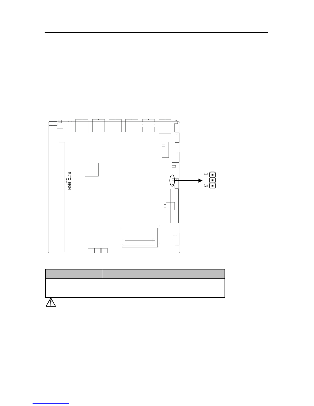
2.4.1 CMOS Clear/Hold Jumper Setting(JCC)
CMOS is powered by the onboard button cell. Clear CMOS will lead to permanent elimination
Page 12
MITX-6934 Intel Cedar Trail Powered 4 Gigabit Mini-ITX Motherboard
5
of previous system settings and back to the original system setting (factory default).
Steps: (( 1 ) Turn off the computer and disconnect the power supply
(2)Use Jumper Cap JCC Pin1-2 short for 5~6 sec. Then restore the default setting
with Pin2-3 connected
(3)Turn on the computer, then press “DEL” key to enter BIOS setting and reload
optimal defaults.
(4)Save and Exit
JCC:
Setting JCC
1-2 BIOS back to intialization (factory dafault)
2-3 Normal Status, System default
Do not clear CMOS when the computor is power on, otherwise, it will cause
damage to the motherboard.
Page 13
MITX-6934 Intel Cedar Trail Powered 4 Gigabit Mini-ITX Motherboard
6
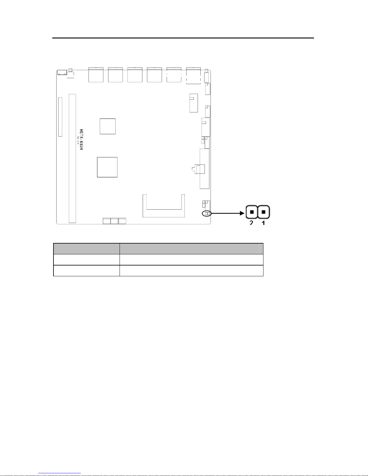
2.4.2 Hardware Switch for System Auto Boot upon Power On(JAT)
JAT:
Setting JAT
Open Disable the auto boot function
Close Enable the auto boot function
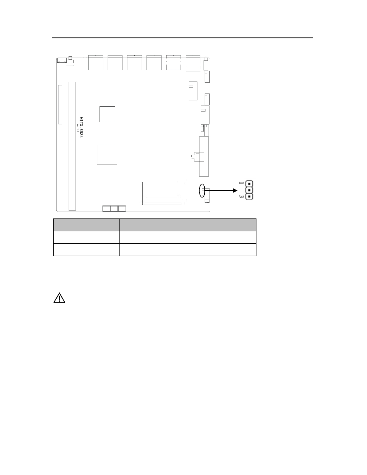
2.4.3 J_WDOG Setting
To setup WATCHDOG function via J_WDOG setting.
Page 14
MITX-6934 Intel Cedar Trail Powered 4 Gigabit Mini-ITX Motherboard
7
Setting J_WDOG
1-2 WATCHDOG
2-3 NC
Note: NC means no watchdog function.
2.5 Interfaces Description
Please read the following instructions carefully before you connecting the external
connectors in case of any damage caused to the motherboard.
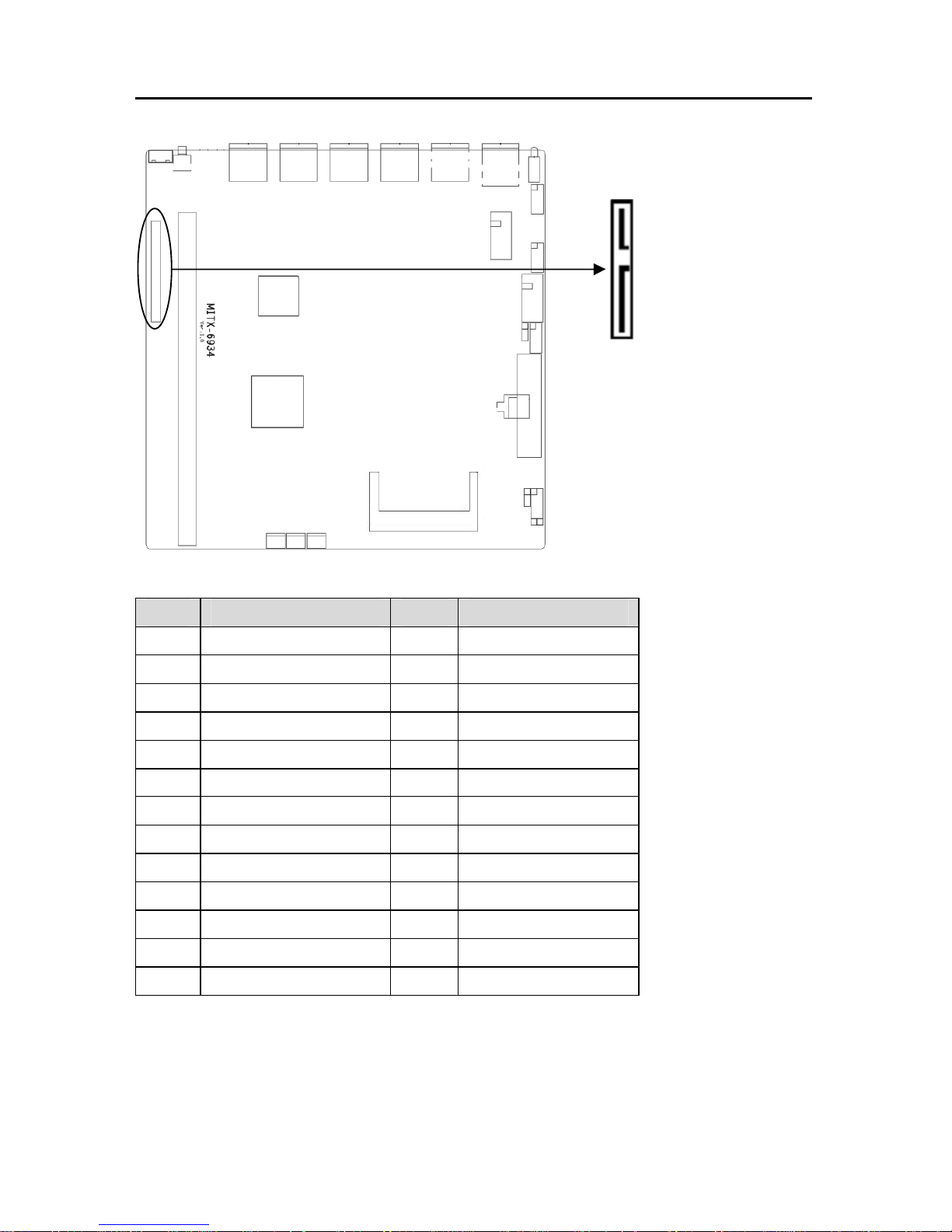
2.5.1 SATA Interface(SATA)
Board provides one 7+15Pin SATA port.
Page 15
MITX-6934 Intel Cedar Trail Powered 4 Gigabit Mini-ITX Motherboard
8
SATA:
Pin Signal Name Pin Signal Name
1 GND P4 GND
2 TX+ P5 GND
3 TX- P6 GND
4 GND P7 VCC
5 RX- P8 VCC
6 RX+ P9 VCC
7 GND P10 GND
8 NC P11 GND
9 GND P12 GND
10 NC P13 +12V
P1 VCC3 P14 +12V
P2 VCC3 P15 +12V
P3 VCC3
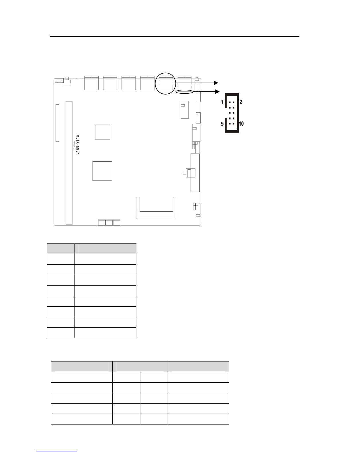
2.5.2 CF Card Socket(Compact Flash)
Board rear panel provides one 50Pin standard CF card socket , supporting TypeⅠ/ⅡCFCard.
Page 16
MITX-6934 Intel Cedar Trail Powered 4 Gigabit Mini-ITX Motherboard
9
2.5.3 Serial Ports(COM1, COM2_LCD)
Board provides 2x serial ports. COM1 is the RJ45 port. COM2_LCD is the 2×5Pin port.
COM1:
Pin Signal Name
1 HRTS#1
2 HDTR#1
3 HSOUT1
4 GND
5 GND
6 HSIN1
7 HDSR#1
8 HCTS#1
COM2_LCD:
Signal Name Pin Signal Name
HDCD# 1 2 HDSR#
HSIN 3 4 HRTS#
HSOUT 5 6 HCTS#
HDTR# 7 8 HRI#
GND 9 10 5V_LCD
COM1-RJ
COM2_LCD
Page 17
MITX-6934 Intel Cedar Trail Powered 4 Gigabit Mini-ITX Motherboard
10
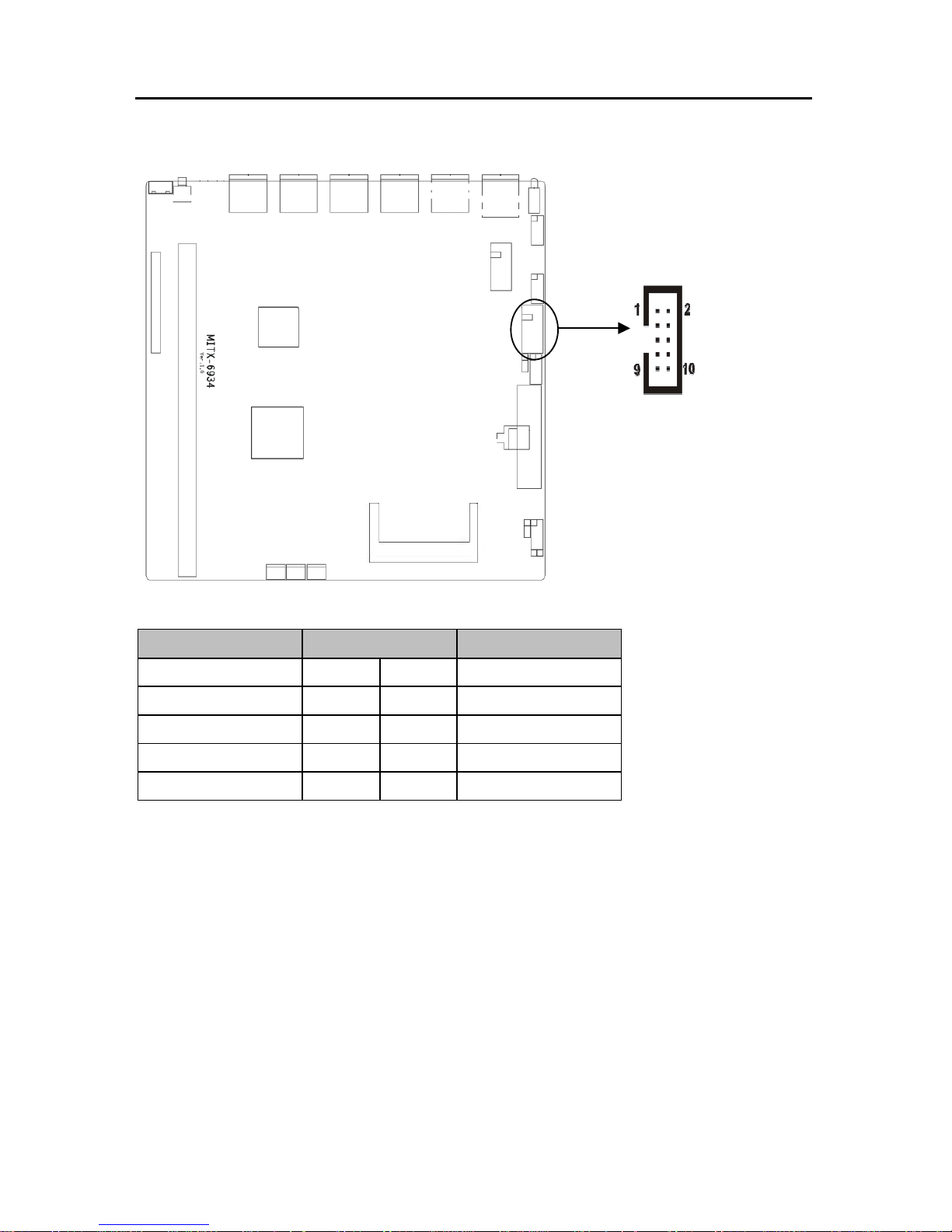
2.5.4 Display Interface(VGA)
VGA:
Signal Name Pin Signal Name
RED 1 2 GND
GREEN 3 4 SDA
BLUE 5 6 HSYNC
GND 7 8 VSYNC
GND 9 10 SCL
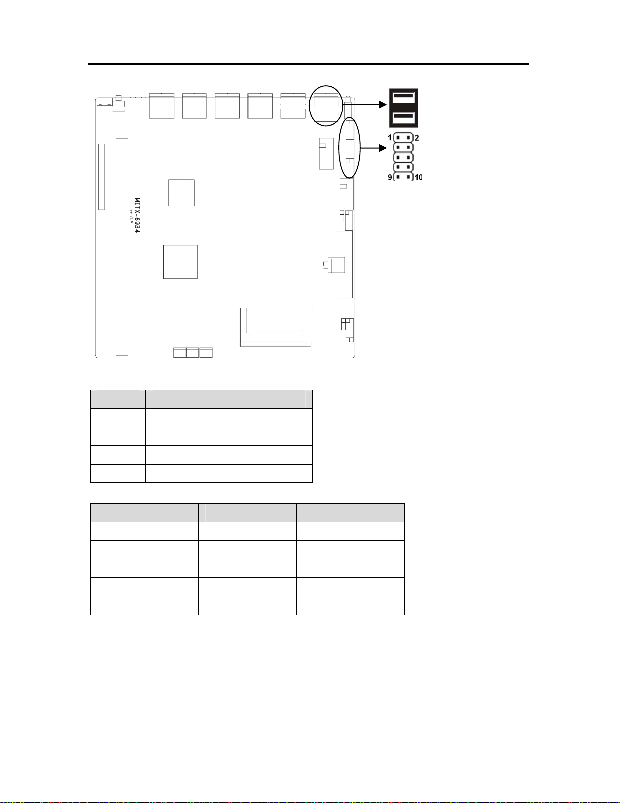
2.5.5 USB Ports(USB12, USB34, USB56)
Board provides 6x USB ports. USB12 is the standard USB 2.0 port. USB34 , USB56 are the 2
×5Pin interfaces, able to be converted to 4x standard USB ports.
Page 18
MITX-6934 Intel Cedar Trail Powered 4 Gigabit Mini-ITX Motherboard
11
Standard USB Port:
Pin Signal Name
1 +5V
2 USB DATA-
3 USB DATA+
4 GND
USB_34, USB_5:
Signal Name Pin Signal Name
VCC 1 2 GND
USB DATA- 3 4 GND
USB DATA+ 5 6 USB DATA+
GND 7 8 USB DATA-
GND 9 10 VCC
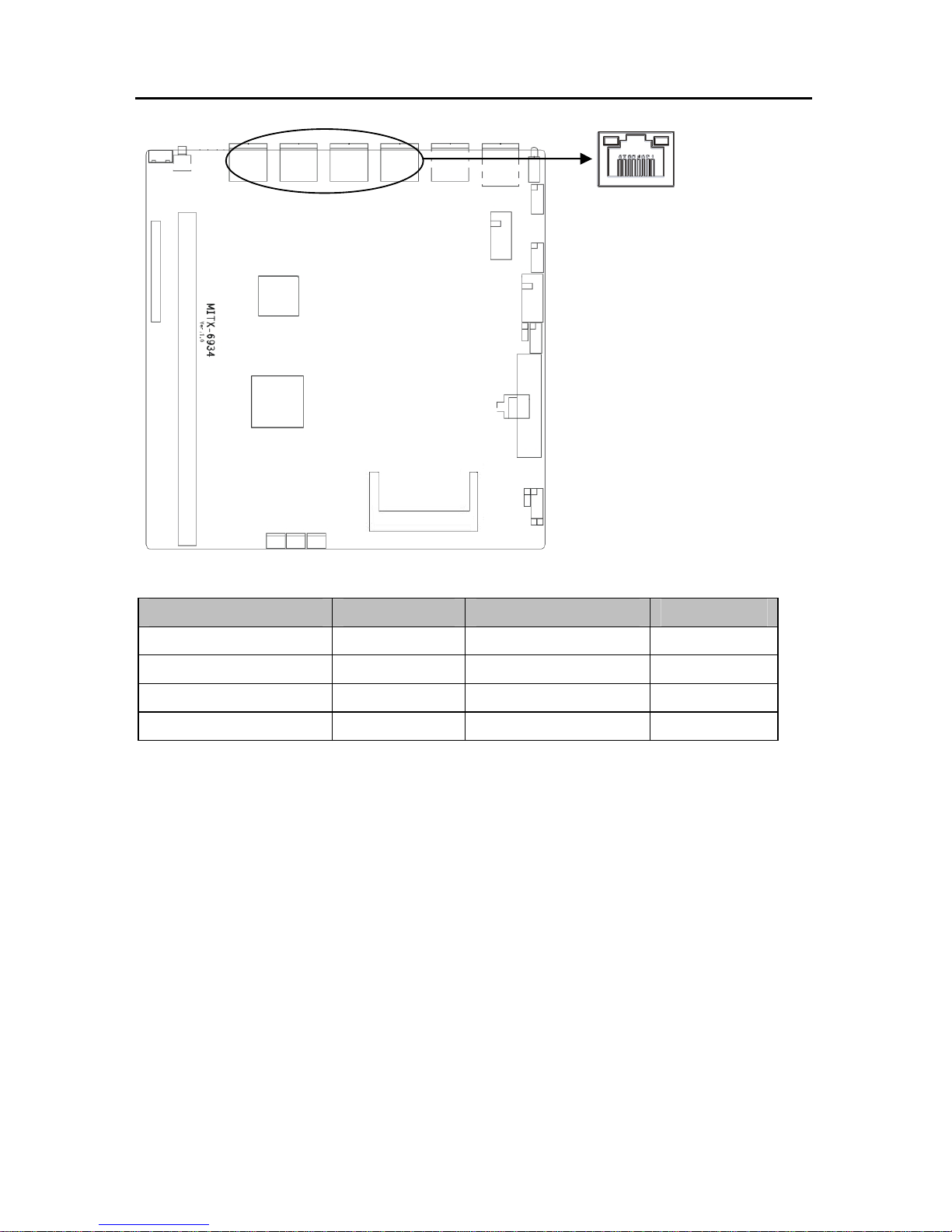
2.5.6 Network Interface(LAN1, LAN2, LAN3, LAN4)
Board provides 4x Gigabit Ethernet Ports.
Page 19
MITX-6934 Intel Cedar Trail Powered 4 Gigabit Mini-ITX Motherboard
12
LED Status:
LILED(Green/Orange)
Function
ACTLED(Yellow)
Function
Green 1000M Link Flash Data Transfer
Orange 100M Link Flash Data Transfer
OFF 10M Flash Data Transfer
OFF No Link OFF No Data
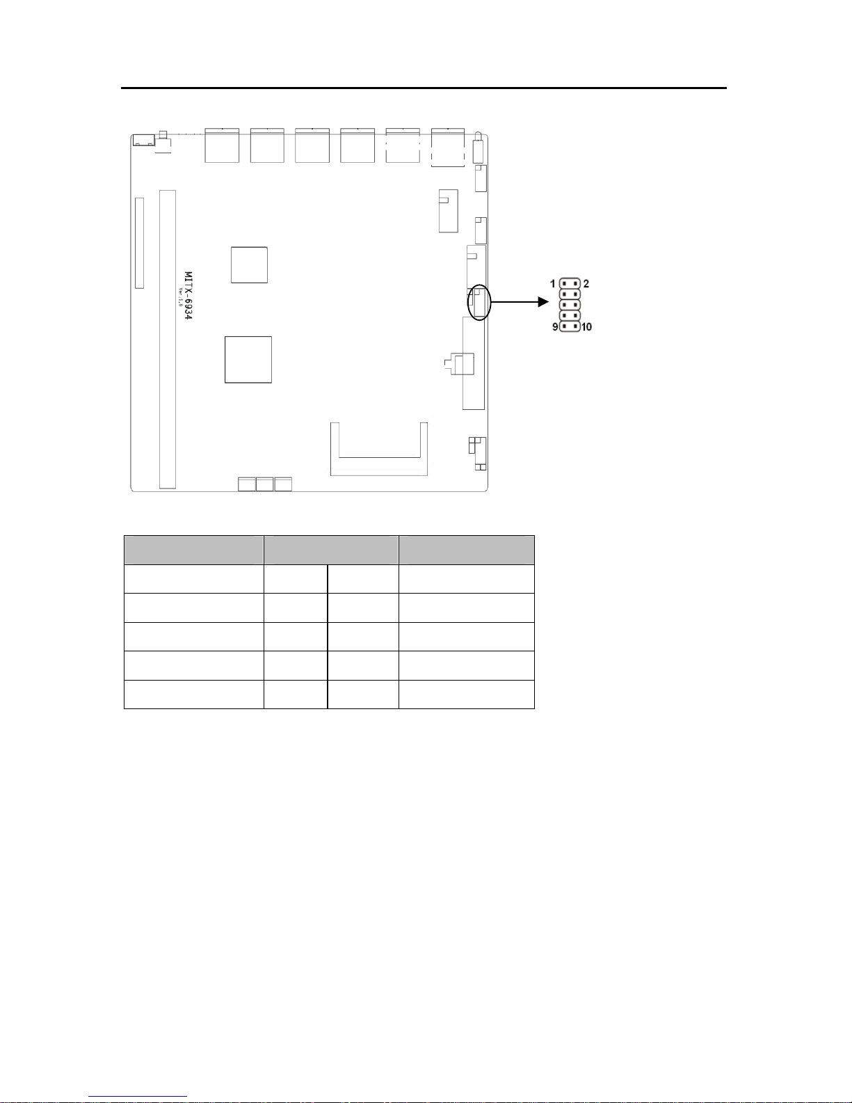
2.5.7 Programmable Input/Output Interface(JGP)
General Purpose Input and Output. 8bit GPIO. One 2x5Pin header.
Page 20
MITX-6934 Intel Cedar Trail Powered 4 Gigabit Mini-ITX Motherboard
13
GPIO:
Signal Name Pin Signal Name
SIO_GP24 1 2 VCC
SIO_GP25 3 4 SIO_GP20
SIO_GP26 5 6 SIO_GP21
SIO_GP27 7 8 SIO_GP22
GND 9 10 SIO_GP23
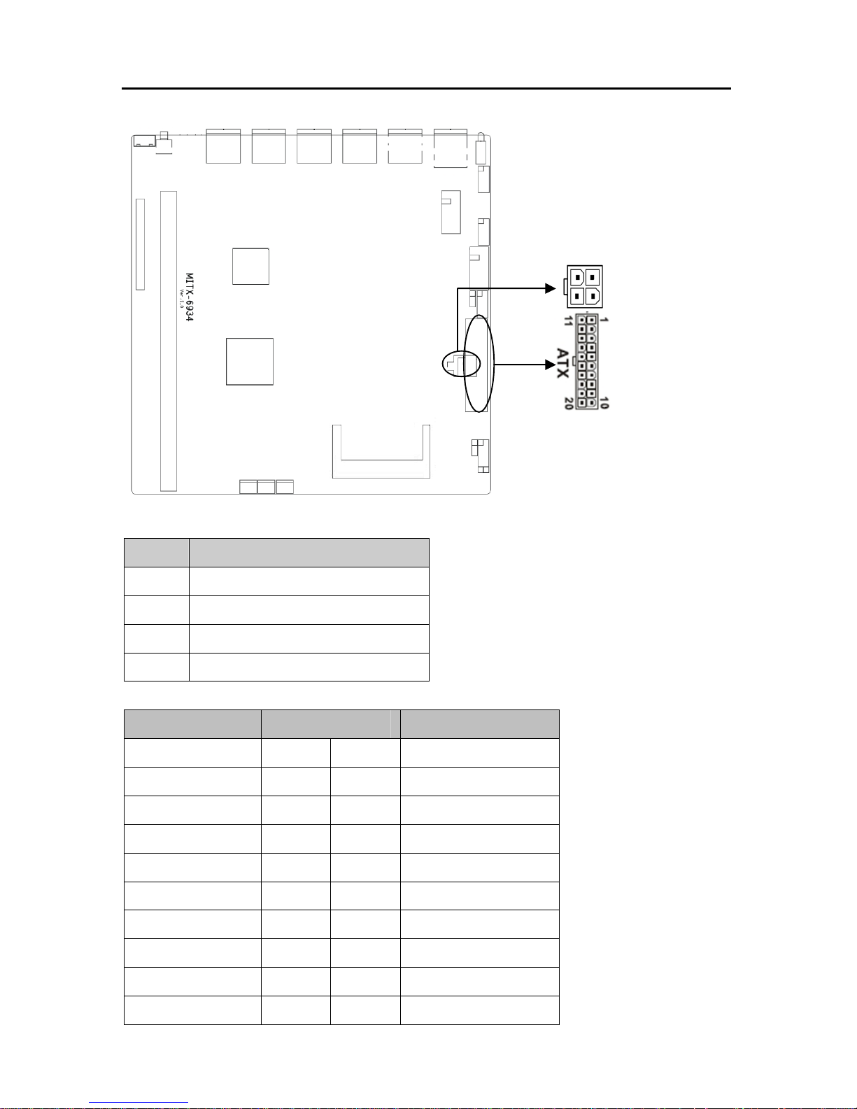
2.5.8 Power Interface(PWR, ATX)
System supports two power mode. The +12V single power(PWR)and the ATX power(ATX).
Single power and ATX power defined as below:
Page 21
MITX-6934 Intel Cedar Trail Powered 4 Gigabit Mini-ITX Motherboard
14
PWR:
Pin Signal Name
1 GND
2 GND
3 +12V
4 +12V
ATX:
Signal Name Pin Signal Name
+3.3V 1 11 +3.3V
+3.3V 2 12 -12V
GND 3 13 GND
+5V 4 14 PS-ON
GND 5 15 GND
+5V 6 16 GND
GND 7 17 GND
PW-OK 8 18 -5V
+5V SB 9 19 +5V
+12V 10 20 +5V
Page 22
MITX-6934 Intel Cedar Trail Powered 4 Gigabit Mini-ITX Motherboard
15
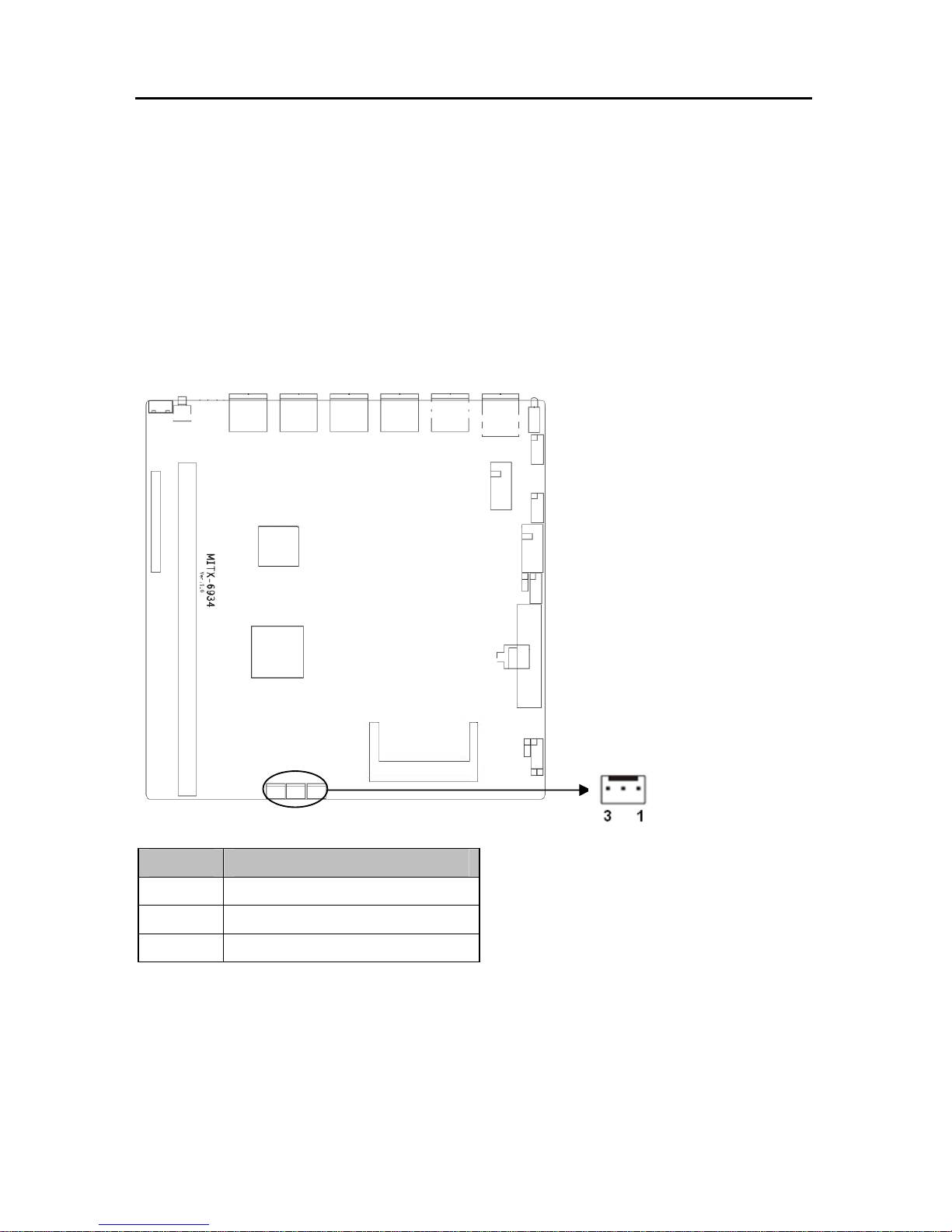
2.5.9 FAN Connector(SYS_FAN1, SYS_FAN2, SYS_FAN3)
Board provides 3x SYSFAN. Please pay attention to following remarks:
(1) The electric current of the FAN ≤350mA(4.2W, 12V)
(2) Please check if the fan cable matches the socket wiring. The power cable is
generallythe red one in the middle. Then the grounding cable (black) and the FAN speed pulse
signal out cable (other color). Some FANs without speed detect function but the output voltage
upto 12V, which will damage the motherboard. Recommend to use FANs with speed detect
function.
SYS_FAN1-3:
Pin Signal Name
1 GND
2 +12V
3 NC
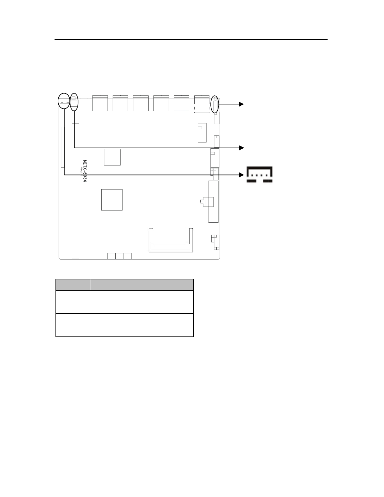
2.5.10 Onboard LED and Buttons(PWR_OUT, FACTORYMOD, LED_4)
PWR_OUT is a 4Pin socket to supply power for LED. VCC max. output current is 500mA.
VCC3 max. output current is 800mA. FACTORYMOD is the reset button. When system goes
wrong and can not continue to working, the reset buttong enables system to restart working
without turning on/off the power, so as to prolong system lifespan. The GREEN LED is the
Page 23
MITX-6934 Intel Cedar Trail Powered 4 Gigabit Mini-ITX Motherboard
16
power LED. This LED will on when system is power on. The red LED is the HDD LED. When
HDD read/write, the LED is on.
PWR_OUT:
Pin Signal Name
1 VCC
2 GND
3 VCC3
4 GND
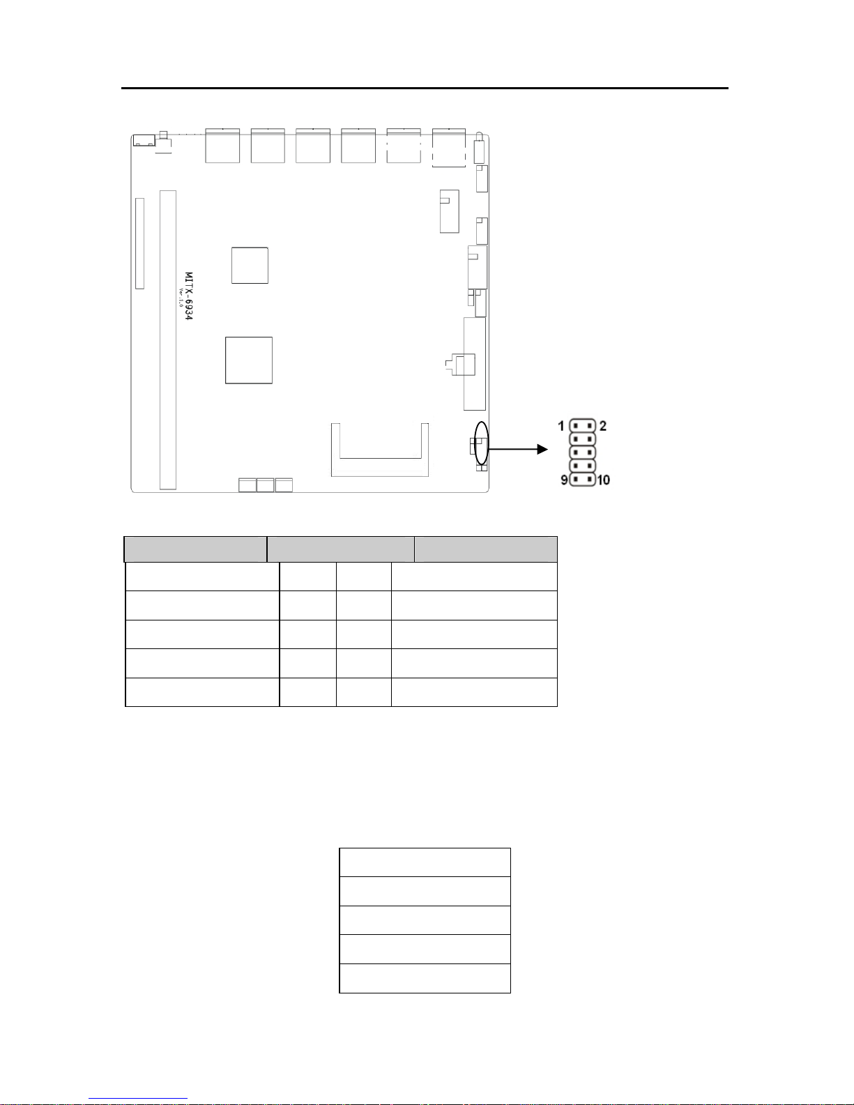
2.5.11 Front Panel Connector(JFP)
One 2x5Pin front panel connector to connect the front panel function buttons and LED
indicators.
Reset Button
PWR LED
HDD LED
Page 24
MITX-6934 Intel Cedar Trail Powered 4 Gigabit Mini-ITX Motherboard
17
JFP:
Signal Name Pin Signal Name
POWER LED+ 1 2 POWER LED-
HD LED+ 3 4 HD LED-
NC 5 6 GND
RESET BUTTON 7 8 GND
POWER BUTTON 9 10 GND
Please follow the table below to connect, pay attention to the anode(+) and cathode(-).
Improper connection will lead to system malfunction.
POWER LED
HDD LED
RESET BUTTON
POWER BUTTON
Page 25

MITX-6934 Intel Cedar Trail Powered 4 Gigabit Mini-ITX Motherboard
18
1)System Power LED Pins(Pin1-2: PWRLED)
Connect system power LED cable with these pins.(pin 1 is LED anode)When system is
power on, power LED is on;when system is power off, power LED is off.
2)HDD LED Pins ( pin3,pin4 for HDD LED)
Case panel with one HD status indicating LED. When HD read and write, the LED will flash,
indicating the device is working. Connect the LED cable to the LED pins ( Pin3 is LED anode).
3)Buzzer Pins(Pin 5-6 for SPEAKER )
External speaker pins
4)Reset Button Pins(Pin 7-8 for RESET )
Connect the RESET button cable to these two pins. When system fails, the reset function
can make the system continue to work without turning on/off the power supply, so as to prolong
system life span.
5)Power on/off button(Pin910 for POWER BUTTON)
Connect the two Pins to the bounce-switch on panel, to connect or disconnect the power.
2.5.12 DIMM Slot(DIMM)
Board with one single channel U-DIMM slot supports DDRIII 800/1066 (desktop RAM) upto
4GB.
2.6 LAN BYPASS Function
2.6.1 What is LAN BYPASS Function
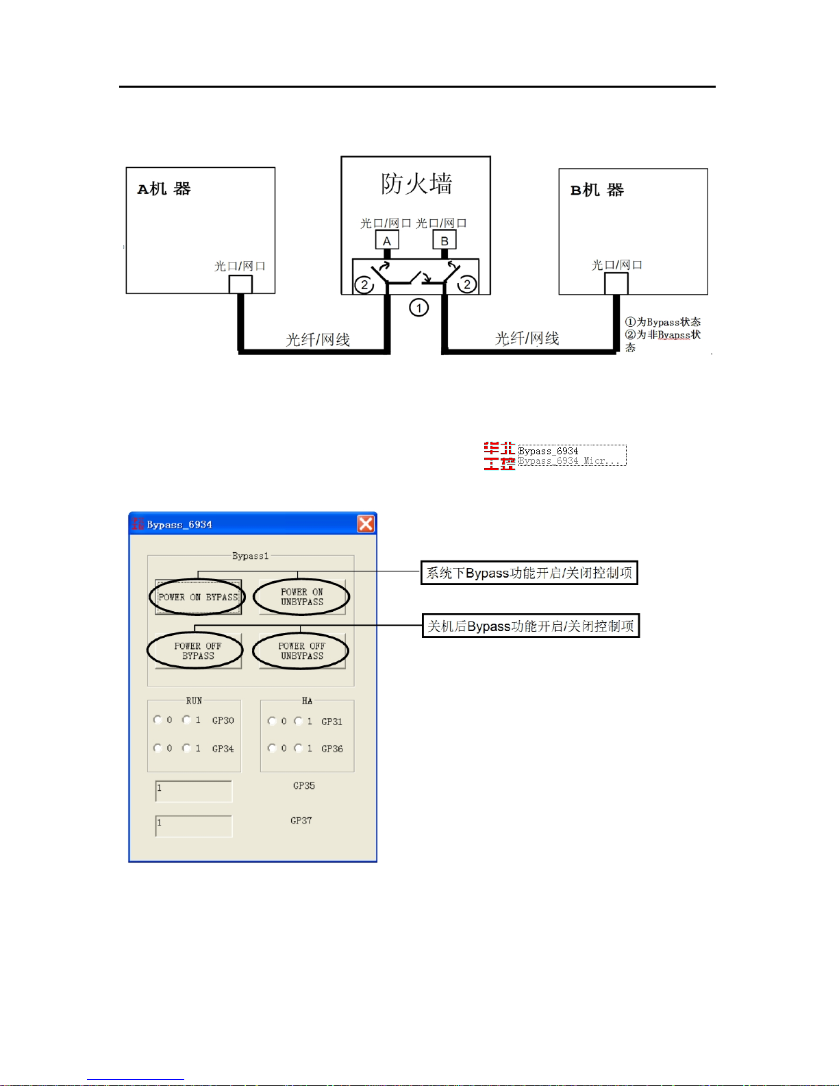
LAN Bypass feature removes a single point of failure so that essential business communication
can continue while a network failure is diagnosed and resolved. In the event of a power,
hardware or software failure. Hardware Bypass will automatically activate,allowing network
traffic to continue. Traffic between the LAN and WAN is allowed without interruption. In the
event of a system hang, power down, hardware or software failure, Hardware Bypass will
automaticallyactivate allowing network traffic to continue.
Page 26
MITX-6934 Intel Cedar Trail Powered 4 Gigabit Mini-ITX Motherboard
19
2.6.2 BYPASS Function Block Diagram
2.6.3 Setup BYPASS in BIOS & WINDOWS/LINUX
To setup BYPASS in BIOS. Details pls refer to the “BYPASS Power ON/ BYPASS Power Off”
option in Chipset Menu.
Setup BYPASS in WINDOWS: double-click the icon to open the
software interface as below:
Setup BYPASS in LINUX:
Run batch file Bypass_6934, following prompts popup. Input character as per the prompts to
select corresponding functions:
Power On Bypass: Input“a,1” and press [Enter];
Power On Unbypass:Input“a,0” and press [Enter];
Page 27

MITX-6934 Intel Cedar Trail Powered 4 Gigabit Mini-ITX Motherboard
20
Power Off Bypass: Input“A,1” and press [Enter];
Power Off unbypass: Input“A,0” and press [Enter];
Exit: Input“qt” and press [Enter]
Page 28

Chapter 3 BIOS SETUP
Page 29

MITX-6934 Intel Cedar Trail Powered 4 Gigabit Mini-ITX Motherboard
20
Chapter 3 BIOS SETUP
AMI BIOS Upgrading
It is true that hardware and software are upgrading all the time. When your IPC can not support
the newest processor (for example), you should upgrade the BIOS to try to keep up with the
latest technology. Upgrading (or flashing) the BIOS is not an easy attempt. To make sure
upgrade succeed, please follow the instruction below:
AFUDOS.EXE is the program for BIOS to modify and upgrade,need to be run in DOS mode.
Use boot disk load DOS, run AFUDOS.EXE and write the newest file: XXXX.ROM into the
Flash IC.
Order Format:
A:\ Afudos XXXX.rom / P /B /N /X
If you need to add other parameters, please add <space>/? after the order format.
Remarks:
1. Upgrading BISO may cause your system crash, so please operate carefully.
2. Please use the upgrading program in the CD-ROM provided by us or download the latest
program on related websites
3. Please do not power off or reboot the system when upgrading, otherwise, the BIOS maybe
be damaged.
4. After BIOS flash, to load default optimum manually
5. Please backup your BIOS before upgrading.
AMI BIOS Description
When the computer is power on, BIOS will conduct self-diagnosis to its hardware on
motherboard and configure hardware parameter, finally the operating system will take control.
BIOS is the communication bridge between hardware and O/S. Correct configuration of BIOS
is critical for maintaining system stability and its optimized performance.
BIOS Settings
1. Power on or reboot the computer, self-detection information will show:
2. When message shows as "Press <DEL> to enter setup",pls press <DEL>, then enter into
BIOS SETUP Program.
3. Use the “←↑→↓”to choose the option which your want to modify, press <Enter> to go to
Page 30
MITX-6934 Intel Cedar Trail Powered 4 Gigabit Mini-ITX Motherboard
21
its sub-menu.
4. Use the “←↑→↓”and <Enter> to modify the value of the chosen option, then press”Enter”
to modify BIOS options that you choose
5. At any time, press<Esc> can go back to the father-menu.
Remark! BIOS settings have direct impatcs to computer performance. Incorrect configurations
will cause damage to the computer and even lead to system halted. Please use BIOS default
settings to recovery system. As our company is aways ceaselessly update the BIOS SETUP
Utility, so, following BIOS SETUP screens are only for your reference. Some may be
differenct from the BIOS you are using now.
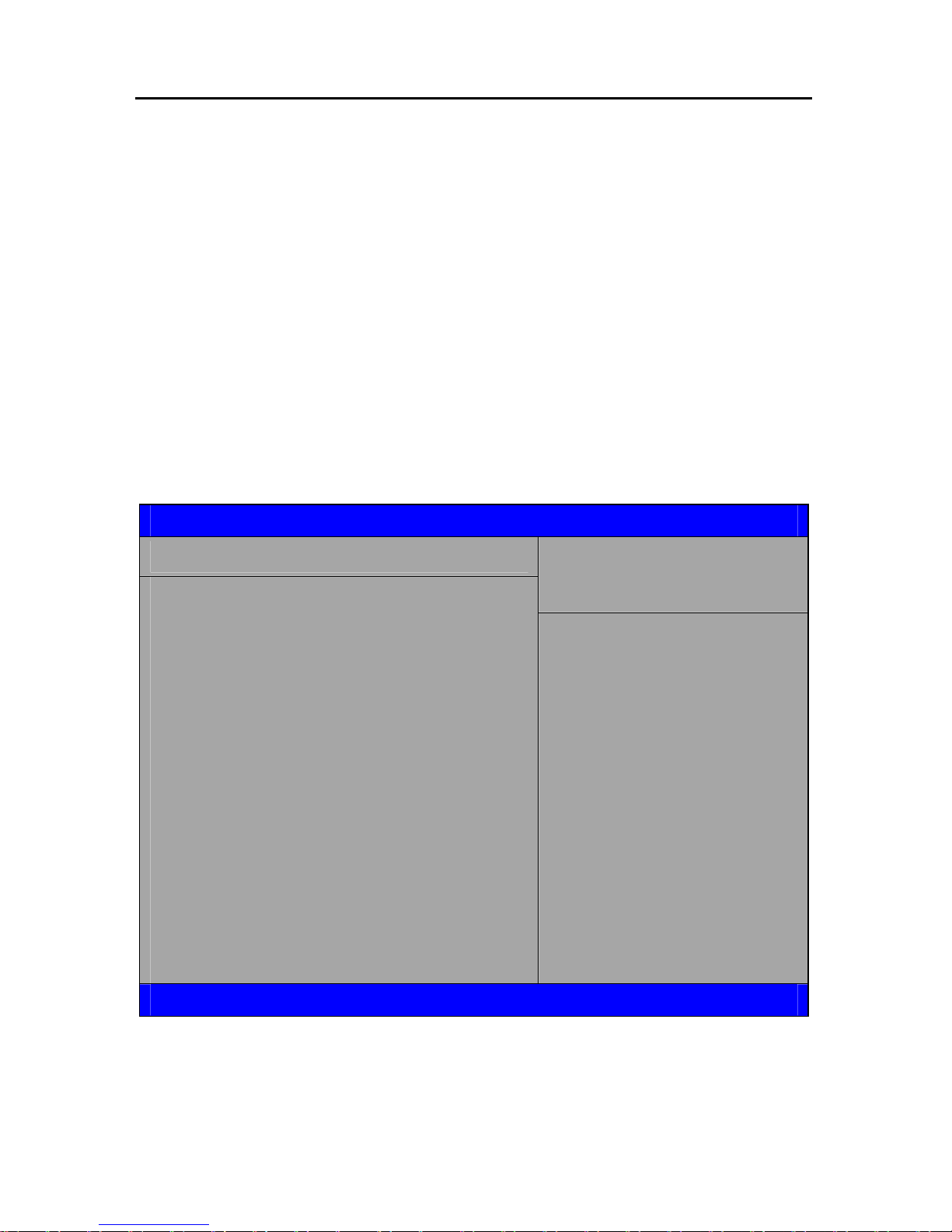
3.1 Main Menu
BIOS SETUP UTILITY
BIOS Information
Set the Date. Use Tab to switch
between Date elements.
BIOS Vendor American Megatrends
Project Version 6934T101
Build Date and Time 06/18/2012 10:38:49
CPU Information
Intel(R) Atom(TM) CPU D2550 @ 1.86GHz
Memory Information
Memory Frequency 1067 MHz(DDR3)
Total Memory 2048 MB
System Date [Mon 06/26/2012]
System Time [11:08:24]
→←:Select Screen
↑↓:Select Item
Enter:Select
+/-:Change Opt.
F1:General Help
F2:Previous Values
F9:Optimized Defaults
F10:Save&Exit
ESC:Exit
Version 2.10.1208. Copyright(C)2010 American Megatrends,Inc.
System Time
System time format: Hour/Minute/Second.
System Date
Page 31
MITX-6934 Intel Cedar Trail Powered 4 Gigabit Mini-ITX Motherboard
22
System Date Format: Week/Month/Day/Year.
3.2 Advanced Menu
BIOS SETUP UTILITY
BIOS Information
Enabled or Disabled Boot Option
for Legacy Network Devices.
Legacy OpROM Support
Launch LAN1 PXE OpROM [Disabled]
Launch LAN2 PXE OpROM [Disabled]
Launch LAN3 PXE OpROM [Disabled]
Launch LAN4 PXE OpROM [Disabled]
ACPI Settings
APM Configuration
CPU Configuration
SATA Configuration
USB Configuration
Super IO Configuration
H/W Monitor
Serial Port Console Redirection
→←:Select Screen
↑↓:Select Item
Enter:Select
+/-:Change Opt.
F1:General Help
F2:Previous Values
F9:Optimized Defaults
F10:Save&Exit
ESC:Exit
Version 2.10.1208. Copyright(C)2010 American Megatrends,Inc.
Launch LAN1/2/3/4 PXE OpROM
Enables or disables the boot option for legacy network devices connected to LAN1/2/3/4.
3.2.1 ACPI Settings
BIOS SETUP UTILITY
ACPI Settings
ACPI Sleep State [S1(CPU Stop Clock)]
Select the highest ACPI sleep
state the system will enter when
the SUSPEND button is pressed.
Page 32
MITX-6934 Intel Cedar Trail Powered 4 Gigabit Mini-ITX Motherboard
23
→←:Select Screen
↑↓:Select Item
Enter:Select
+/-:Change Opt.
F1:General Help
F2:Previous Values
F9:Optimized Defaults
F10:Save&Exit
ESC:Exit
Version 2.10.1208. Copyright(C)2010 American Megatrends,Inc.
ACPI Sleep State
Select the highest ACPI sleep state the system will enter when the suspend button is pressed.
Different modes are defined with different power consumption.
S1 (CPU Stop Clock): CPU stops working while other devices are still connected to power
supply.
3.2.2 APM Configuration
BIOS SETUP UTILITY
RTC Power On Function [Enabled]
RTC Power On Hour 0
RTC Power On Minute 0
RTC Power On Second 0
Enable or disable System wake on
alarm event. When enabled.
System will wake on the
hr::min::sec specified
Page 33
MITX-6934 Intel Cedar Trail Powered 4 Gigabit Mini-ITX Motherboard
24
→←:Select Screen
↑↓:Select Item
Enter:Select
+/-:Change Opt.
F1:General Help
F2:Previous Values
F9:Optimized Defaults
F10:Save&Exit
ESC:Exit
Version 2.10.1208. Copyright(C)2010 American Megatrends,Inc.
RTC Power On Function
When Enabled, users can set the date and time at which the RTC (real time clock) alarm
awakens the system from Suspend mode. The choices :< Enabled>, <Disabled (default)>.
3.2.3 CPU Configuration
BIOS SETUP UTILITY
CPU Configuration
Enabled for Windows XP and
Linux (OS optimized for
Hyper-Threading Technology)and
Disabled for other OS(OS not
optimized for Hyper-Threading
Technology).
Processor Type Intel(R) Atom(TM) CPU
EMT64 Supported
Processor Speed 1865 MHz
Ratio Status 14
Actual Ratio 14
System Bus Speed 533 MHz
Processor Stepping 30661
Microcode Revision 268
L1 Cache RAM 2×56 K
L2 Cache RAM 2×512 K
Processor Core Dual
Hyper-Threading Supported
Hyper-Threading [Enabled]
Execute Disabled Bit [Enabled]
→←:Select Screen
↑↓:Select Item
Enter:Select
+/-:Change Opt.
F1:General Help
F2:Previous Values
F9:Optimized Defaults
F10:Save&Exit
ESC:Exit
Page 34

MITX-6934 Intel Cedar Trail Powered 4 Gigabit Mini-ITX Motherboard
25
Limit CPUID Maximum [Disabled]
EIST [Disabled]
CPU C state Report [Disabled]
Version 2.10.1208. Copyright(C)2010 American Megatrends,Inc.
The read only option contains detailed information of CPU, including CPU manufacturer,
model,frequency, L1 Cache, L2 Cache, etc.
Hyper-Threading
Disable or enable the Hyper-Threading Technology.
Intel® Hyper-Threading Technology uses resources efficiently, enabling multiple threads to run
on each core, and increasing processor throughput.
Execute Disabled Bit
When this field is set to Disabled, it will force the XD feature flag to always return to 0. XD can
prevent certain classes of malicious buffer overflow attacks when combined with a supporting
OS (Windows Server 2003 SP1, Windows XP SP2, SuSE Linux 9.2, RedHat Enterprise 3
Update 3).
Limit CPUID Maximum
The CPUID instruction of some newer CPUs will return a value greater than 3. The default is
Disabled because this problem does not exist in the Windows series operating systems. If you
are using an operating system other than Windows, this problem may occur. To avoid this
problem, enable this field to limit the return value to 3 or lesser than 3.
EIST
To enable or disable the Enhanced Intel SpeedStep Technology (EIST). Enhanced Intel
Page 35

MITX-6934 Intel Cedar Trail Powered 4 Gigabit Mini-ITX Motherboard
26
SpeedStep Technology allows the system to dynamically adjust processor voltage and core
frequency, which can result in decreased average power consumption and decreased average
heat production.
CPU C state Report
Enable or disable the CPU C-states.
3.2.4 SATA Configuration
BIOS SETUP UTILITY
SATA Configuration
SATA Ports (0-3) Device Names if
Present and Enabled.
Serial ATA Port1 Not Present
Serial ATA Port2 Not Present
Serial-ATA Controller(s) [Enabled]
SATA Mode [AHCI]
Serial ATA Port1 [Enabled]
Serial ATA Port2 [Enabled]
→←:Select Screen
↑↓:Select Item
Enter:Select
+/-:Change Opt.
F1:General Help
F2:Previous Values
F9:Optimized Defaults
F10:Save&Exit
ESC:Exit
Version 2.10.1208. Copyright(C)2010 American Megatrends,Inc.
Serial-ATA Controller(S)
To enable or disable the SATA controller (S).
SATA Mode
To configure the SATA Mode:[AHCI] or [IDE].
Serial ATA Port1/2
To enable or disable the two ports (SATA & CF) under AHCI mode.
Page 36
MITX-6934 Intel Cedar Trail Powered 4 Gigabit Mini-ITX Motherboard
27
3.2.5 USB Configuration
BIOS SETUP UTILITY
USB Configuration
Enable / Disable USB Function.
USB Devices:
1 Keyboard ,1 Mouse
USB function [Enabled]
USB 2.0 (EHCI) Support [Enabled]
Legacy USB Support [Enabled]
Mass Storage Devices;
KingstonDataTraveler G2 PMAP [Auto]
→←:Select Screen
↑↓:Select Item
Enter:Select
+/-:Change Opt.
F1:General Help
F2:Previous Values
F9:Optimized Defaults
F10:Save&Exit
ESC:Exit
Version 2.10.1208. Copyright(C)2010 American Megatrends,Inc.
USB function
To enable or disable the USB port.
USB 2.0 (EHCI) Support
[Enabled]: Enable USB EHCI (USB 2.0) functions, max. transmission rate upto 480Mpbs
[Disabled]: Disable USB2.0 function. The transmission rate is 12Mpbs.
Legacy USB Support
To support USB device in DOS mode: such as USB Flash Disk, USB keyboard, please select
<Enabled> or<Auto>.If not , pls select < Disabled>.
Mass Storage Devices
To select the types of the connected USB devices. [Auto], or [ floppy] or [Forced FDD], [HDD ]
or CD-ROM. System defaults as [Auto].
3.2.6 Supper IO Configuration
BIOS SETUP UTILITY
Super IO Configuration
Set Parameters of Serial Port 1
Page 37
MITX-6934 Intel Cedar Trail Powered 4 Gigabit Mini-ITX Motherboard
28
(COMA)
Serial Port 1 Configuration
Serial Port 2 Configuration
→←:Select Screen
↑↓:Select Item
Enter:Select
+/-:Change Opt.
F1:General Help
F2:Previous Values
F9:Optimized Defaults
F10:Save&Exit
ESC:Exit
Version 2.10.1208. Copyright(C)2010 American Megatrends,Inc.
Serial Port 1 Configuration
1)Serial Port
To enable or disable the serial port functions.
2)Device Setting(Read Only)
Display serial port IRQ and base address.
3)Change Setting
To change serial port settings. Recommend to select [Auto].
Serial Port 2 Configuration follows the same steps as above.
3.2.7 H/W Monitor
BIOS SETUP UTILITY
PC Health Status
SYSTIN temperature : +28℃
Page 38
MITX-6934 Intel Cedar Trail Powered 4 Gigabit Mini-ITX Motherboard
29
CPUTIN temperature : +41℃
CPUVCore : +1.192V
+3.3VIN : +3.328V
+5VIN : +4.992V
VBAT : +3.296V
→←:Select Screen
↑↓:Select Item
Enter:Select
+/-:Change Opt.
F1:General Help
F2:Previous Values
F9:Optimized Defaults
F10:Save&Exit
ESC:Exit
Version 2.10.1208. Copyright(C)2010 American Megatrends,Inc.
PC Health Status
PC Health Status Detect. BIOS will display current system temperature, CPU temperature,
FAN rotate speed, and related voltage value.
3.2.8 Serial Port Console Redirection
BIOS SETUP UTILITY
Console Redirection Enable or
Disable.
COM1
Console Redirection [Disabled]
Console Redirection Settings
Serial Port for Out-of-Band Management/
Windows Emergency Management
Services(EMS)
Console Redirection [Disabled]
Console Redirection Settings
→←:Select Screen
↑↓:Select Item
Enter:Select
+/-:Change Opt.
F1:General Help
F9:Optimized Defaults
F10:Save&Exit
ESC:Exit
Version 2.10.1208. Copyright(C)2010 American Megatrends,Inc.
Console Redirection
To enable or disable the console redirection function.
Page 39
MITX-6934 Intel Cedar Trail Powered 4 Gigabit Mini-ITX Motherboard
30
3.3 Chipset Menu
BIOS SETUP UTILITY
North Bridge Parameters South Bridge
→←:Select Screen
↑↓:Select Item
Enter:Select
+/-:Change Opt.
F1:General Help
F2:Previous Values
F9:Optimized Defaults
F10:Save&Exit
ESC:Exit
Version 2.10.1208. Copyright(C)2010 American Megatrends,Inc.
3.3.1 South Bridge
BIOS SETUP UTILITY
South Bridge
Audio Controller
LAN1 Controller [Enabled]
LAN2 Controller [Enabled]
LAN3 Controller [Enabled]
LAN4 Controller [Enabled]
Restore AC Power Loss [Power On]
Power On Bypass [Disabled]
Power Off Bypass [Disabled]
→←:Select Screen
↑↓:Select Item
Enter:Select
+/-:Change Opt.
F1:General Help
F2:Previous Values
F9:Optimized Defaults
F10:Save&Exit
ESC:Exit
Version 2.10.1208. Copyright(C)2010 American Megatrends,Inc.
LAN 1-4 Controller
To enable or disable the onboard LAN Controller.
Page 40

MITX-6934 Intel Cedar Trail Powered 4 Gigabit Mini-ITX Motherboard
31
Restore AC Power Loss
This option is to setup the system status while connecting the power again after the AC Power
Loss
<Power Off>:System remains the status of power off. Users need to press the power button to
start the computer.
<Power On>: System will reboot automatically when connecting to power supply.
<Last State>: Remain the same state as that before the power loss.
Bypass Power On
BYPASS enabled or disabled when system is power on.
Bypass Power Off
Bypass enabled or disabled when system is power off.
3.4 Boot Menu
BIOS SETUP UTILITY
Boot Configuration
Number of seconds to wait for
setup activation key. 65535(0×
FFFF) means indefinite waiting.
Setup Prompt Timeout 1
Bootup Numlock State [On]
Show Full Logo [Enabled]
Boot Option Priorities
Boot Option #1 [SATA PM:WDC WD10… ]
Boot Option #2 [UEFI: Built-in EFI…]
Hard Drive BBS Priorities
→←:Select Screen
↑↓:Select Item
Enter:Select
+/-:Change Opt.
F1:General Help
F2:Previous Values
F9:Optimized Defaults
F10:Save&Exit
ESC:Exit
Version 2.10.1208. Copyright(C)2010 American Megatrends,Inc.
Setup Prompt Timeout
Number of seconds to wait for setup shortcut key. 60s is the max seconds of timeout. If don’t
Page 41

MITX-6934 Intel Cedar Trail Powered 4 Gigabit Mini-ITX Motherboard
32
press Setup key within the preset time, system will contiune to start.
Bootup Numlock State
This function allows users to activate Numlock function when boot up.
[ON]:Numlock open when boot up
[OFF]: Numlock under cursor control
Show Full Logo
[Enabled]: Computer boot screen will show supplier’s LOGO.
[Disabled]: Self-detect info will show when system boots.
Boot Option #1/2
System will detect devices according to the preset sequency until to find a boot device. Option
#1 is the prior boot device.
Hard Drive BBS Priorities
This option contains HDD that can be used as boot device. If multiple HDDs in this option,
priority should set for these HDDs, then the prior one will show in Boot Option #1.
3.5 Security Menu
BIOS SETUP UTILITY
Set Administrator Password Password Description
The password length must be in the following range:
Minimum length 1
Maximum length 20
Administrator Password
User Password
→←:Select Screen
↑↓:Select Item
Enter:Select
+/-:Change Opt.
F1:General Help
F2:Previous Values
F9:Optimized Defaults
F10:Save&Exit
ESC:Exit
Page 42
MITX-6934 Intel Cedar Trail Powered 4 Gigabit Mini-ITX Motherboard
33
Version 2.10.1208. Copyright(C)2010 American Megatrends,Inc.
The password length: Min: 1 character, Maximum: 20 characters.
Administrator Password
To setup administrator password.
User Password
To set User Password. If you have set the password, system will display “Installed”; If not,
system will display ”Not Installed”.
3.6 Save & Exit Menu
BIOS SETUP UTILITY
Restore/Load Default values for all
the setup options.
Load Defaults
Save Changes and Exit
Discard Changes and Exit
→←:Select Screen
↑↓:Select Item
Enter:Select
+/-:Change Opt.
F1:General Help
F2:Previous Values
F9:Optimized Defaults
F10:Save&Exit
ESC:Exit
Version 2.10.1208. Copyright(C)2010 American Megatrends,Inc.
Load Defaults
Restore/Load Default values for all the setup options.
Save Change and Exit
Press [Enter] to select this option and press [Enter] to confirm to save all BIOS changes and
Exit.
Page 43

MITX-6934 Intel Cedar Trail Powered 4 Gigabit Mini-ITX Motherboard
34
Discard Change and Exit
Press [Enter] to select this option and press [Enter] to confirm to discard all changes and exit..
Page 44

Appendix
Page 45

35
Appendix
Appendix 1: Watchdog Programming Guide
watchdog reference code(ASM)
--------------------------------------------------------------------------------------------------------------
Set the port to realize watchdog function through DEBUG order, so that it can carry out
Watchdog Timer’s various functions.
Port Instruction:
void main()
{
int indexp = 0x2e,datap = 0x2f;
unsigned char temp;
outportb(indexp,0x87);
outportb(indexp,0x87); //unlock
outportb(indexp,0x2d);
temp = (unsigned char)inportb(datap);
temp &= 0xfe;
outportb(indexp,0x2d);
outportb(datap,temp); //set pin for watchdog
outportb(indexp,0x07);
outportb(datap,0x08);
outportb(indexp,0x30);
outportb(datap,0x01); //enable logical device
outportb(indexp,0xf5);
outportb(datap,0x00); //set second
/*outportb(datap,0x08); set minute*/
outportb(indexp,0xf6);
outportb(datap,0x03); //set 3 seconds
Page 46

MITX-6934 Intel Cedar Trail Powered 4 Gigabit Mini-ITX Motherboard
36
outportb(indexp,0xf7);
outportb(datap,0x00);
outportb(indexp,0xaa); //lock
}
If system halted, the Watchdog function will enable the system to reboot automatically.
Page 47

MITX-6934 Intel Cedar Trail Powered 4 Gigabit Mini-ITX Motherboard
37
Appendix 2: IRQ & System Memory Map,1st MB Memory Map
IRQ:
Priority Interrupt#
Interrupt source
1 NMI Parity error detected
2 00 System timer
3 01 Available
- 02 Interrupt from controller 2 (cascade)
4 08 System CMOS/real time clock
5 09 Microsoft ACPI-Compliant System
6 10 Available
7 11 Available
8 12 Available
9 13 Numeric data processor
10 14 Available
11 15 Available
12 03 Communication port(COM2)
13 04 Communication port(COM1)
14 05 Available
15 06 Available
16 07 Intel(R) N10/ICH7 Family SMBus Controller – 27DA
System Memory Map:
Address Range
(decimal)
Address Range
(hex)
Size Description
1024K – 4194304 K 100000 - FFFFFFFF 4095 MB
Extended memory
960K – 1024K F0000 - FFFFF 64 KB Runtime BIOS
896 K- 960 K E0000 - EFFFF 64 KB Reserved
800 K – 896 K C8000 - DFFFF 96 KB
Potential available high DOS
memory (open to the PCI bus).
Dependent on video adapter
used.
640 K - 800 K A0000 – C7FFF 160 KB Video memory and BIOS
Page 48

MITX-6934 Intel Cedar Trail Powered 4 Gigabit Mini-ITX Motherboard
38
1st MB Memory Map:
639 K – 640 K 9FC00 – 9FFFF 1 KB
Extended BIOS data (movable by
memory manager software)
512 K – 639 K 80000 – 9FBFF 127 KB Extended conventional memory
0 K – 512 K 00000 – 7FFFF 512 KB Conventional memory
Address Range(Hex)
Device
E0000h-FFFFFh BIOS
CC000h-DFFFFh Unused
C0000h-CBFFFh VGA BIOS
A0000h-BFFFFh Video Memory
00000h-9FFFFh Base memory
Page 49

MITX-6934 Intel Cedar Trail Powered 4 Gigabit Mini-ITX Motherboard
39
Appendix 3: Glossary
ACPI
Advanced Configuration and Power Management. ACPI specifications allow O/S to control
most power of the computer and its add-ons
Windows 98/98SE,Windows 2000 and Windows ME all support this function, which enable
users to manage the system power flexibly.
BIOS
Basic input/output system. It’s a kind of software including all in/out control code interface in PC.
It will do hardware testing while system is booting, then system runs, it provides an interface
between OS and hardware. BIOS is stored in a ROM chip.
BUS
In a computer system, it is the channel among different parts for exchanging data; it’s also a
group of hardware lines. BUS here refers to part lines inside CPU and main components of
memory.
Chipset
Integrated chips for executing one or more functions. Here “Chipset” refers to system level
chipset structured by Southbridge & Northbridge; it determines motherboard’s structure and
main functions.
CMOS
Complementary Metal-Oxide Semiconductor, a widely used semiconductor with the
characteristic of high speed but low-power-consumption. CMOS here refers to part of reserved
space in on-board CMOS RAM, for saving date, time, system information and system
parameter etc.
COM
Computer-Output Microfilmer. A universal serial communication interface, usually adopts
normative DB9 connector.
Page 50

MITX-6934 Intel Cedar Trail Powered 4 Gigabit Mini-ITX Motherboard
40
DIMM
Dual-Inline-Memory-Module. It’s a small circuit board with memory chipset, providing 64bit
RAM bus width.
DRAM
Dynamic Random Access Memorizer. It’s a normal type of universal memory often with a
transistor and a capacitance to store 1 bit. With the development of the technology, more and
more types of ORAM with various specifications exist in computer application, such as SDRAM,
DDR SDRAM and RDRAM
I2C
I2C(Inter-Integrated Circuit), generically referred to as two-wire interface, is a multi-master
serial single-ended computer bus invented by Philips that is used to attach low-speed
peripherals to a motherboard, embedded system, cellphone, or other electronic device.
LAN
Network interface. Network grouped by correlative computers in a small area, generally in a
company or a building. Local area network is generally buildup by sever, workstation, some
communication links. Terminals can access data and devices anywhere through cables so that
many users can share costly device and resource.
LED
Light-Emitting Diode. a semiconductor device that shines when power supply is connected,
often used to denote info directly by light, for example, to denote power on or HDD work
normally.
PnP
Plug-and-Play. It is a specification that allows PC to configure its external devices automatically
and can work independently without the manual operation by its user . To achieve this function,
its BIOS should be able to support PnP and a PnP expansion card.
POST
Self-test when power on. While booting, BIOS will do an uninterrupted testing to the system,
Page 51

MITX-6934 Intel Cedar Trail Powered 4 Gigabit Mini-ITX Motherboard
41
including RAM, keyboard, hard disk driver etc. to check if all the components are in normal
situation and work well.
PS/2
A keyboard & mouse connective interface specification developed by IBM.PS/2 is a DIN
interface with only 6PIN; it also can connect other devices, like modem.
USB
It is the Universal Serial Bus for short. A hardware interface adapts to low speed external
devices, and is always used to connect keyboard, mouse etc. One PC can connect maximum
127 USB devices, providing 12Mbit/s transmit bandwidth;USB supports hot swap and multi-
data stream, namely, you can plug USB devices while system is running, system can
auto-detect and makes it work.
Page 52

 Loading...