


MITX-6110
User’s Manual V1.0

Announcement
With the exception of showing the accessories of product configuration, this
manual does not create any commitment of our company. We retained the
rights to change it without prior notice and will not be responsible for any
direct, indirect, intentional or unintentional damage or hidden dangers
caused by any improper installation or use.
Before buying products, please learn about the product performance from
the distributors to see if it is in line with your needs. NORCO is a registered
trademark of Shenzhen NORCO Intelligent Technology CO., LTD. The
ownership of other trademarks involved in this manual is owned by its
respective owners.
The contents of this manual are protected by copyright law. All rights are
strictly reserved. Any form of unauthorized reproduction is prohibited,
including but not limited to carbon copy, facsimile transmission and
electronic copy or email, etc.

Safety Instructions
1.Before using this product, please read this user’s manual carefully;
2.Any plate cards not ready to be installed shall be kept in the anti-static protective bags;
3.Before taking out the plate cards from the anti-static protective bags, first place hands on the
grounding metal object for a while so as to release the static electricity from your body and
hands;
4.While fetching the plate cards, please wear static protective gloves and have the habit of
holding the cards by edge;
5.Before connecting the motherboard to the power supply, please check the power voltage
6.In order to prevent bodily electric shock or damage to products, first turn off the
AC power or unplug the power cord out of power sockets while inserting main boards or plate
cards or do reconfiguration;
7.Before moving the plate cards or the unit, please make sure to unplug the AC power cords
out of the sockets;
8.Before you connect or unplug any equipment, please make sure that all power cords are
unplugged in advance;
9.To prevent any unnecessary damage to the products due to frequent power on/off. Please
wait at least 30 seconds before you restart up the unit after the unit is shut down;
10.If anything unexpected happened during the operating, please seek help from
professionals;
11.This is a Class A product, in a domestic environment, this product may cause radio
interference. In this case, the user may be required to take adequate measures.

Content
Chapter 1 Product Introduction...........................................................................................................1
1.1 Product Specification................................................................................................................1
Chapter 2 Installation Instructions......................................................................................................3
2.1 Interface Location and Dimension Diagram..........................................................................3
2.2 Installation Steps.......................................................................................................................3
2.3 Memory Installation...................................................................................................................4
2.4 Jumper Setting...........................................................................................................................4
2.4.1 CMOS Content Clearance /Keep Settings(JCC1、JCC2)
2.4.2 Hardware Switch for System Auto Boot upon Power On(JAT)
2.4.3 Debug Interface(DB_UART)
2.4.4 COM2 Jumper Setting(J1,J2)
2.5 Interface Specification..............................................................................................................8
2.5.1 SATA Interface(SATA1、SATA2、JSATAPWR、MCU_DB)
2.5.2 Serial Ports(HDMI JCOM1、VGA JCOM2)
2.5.3 Display Port(LVDS)
2.5.4 LVDS Voltage and Backlight Setting Interface(JLVDS、JLVDSBTN、JLVDSPWR)
..................................................................................................................................................14
2.5.5 USB Port(USB12、USB34、USB56_USB3_LAN1、USB78_USB_LAN2) 15
2.5.6 Keyboard & Mouse Connector(KBMS)
2.5.7 Programmable I / O Interface(JGP)
2.5.8 Power Interface(PWR1、PWR2、PWR3)
2.5.9 Fan Interface(SYS_FAN、CPU_FAN)
2.5.10 Line Input Pin(LINE_IN)
2.5.11 JLPC Interface(JLPC)
2.5.12 Audio Port(Audio)
2.5.13 BIOS Write Protect Interface(JME)
2.5.14 Front Panel Interface(JFP)
2.5.15 Memory Slot(SO-DIMM)
2.5.16 Expansion Por(PCIE_X1、MINI_ PCIE1、MINI_ PCIE2)
................................................................................................
.................................................................................................
...................................................................................
.............................................................................
.....................................................
...............................................................
.....................................................................
.........................................................
................................................................
......................................................................................
..........................................................................................
...................................................................
.................................................................................
......................................................................................
................................
..........................
.............................
.............................
10
12
16
17
18
19
20
20
22
23
23
25
25
4
6
7
7
8

Chapter 3 BIOS Setup....................................................................................................................... 25
AMI BIOS Reflesh..................................................................................................................25
AMI BIOS Description...........................................................................................................25
BIOS Parameter Setting.......................................................................................................25
3.1 Main Menu................................................................................................................................26
3.2 Advanced..................................................................................................................................27
3.2.1 ACPI Settings............................................................................................................... 28
3.2.2 CPU Configuration.......................................................................................................29
3.2.3 SATA Drives................................................................................................................. 31
3.2.4 USB Configuration.......................................................................................................32
3.2.5 F81804 Supper IO Configuration.............................................................................. 33
3.2.6 Hardware Monitor........................................................................................................ 35
3.2.7 Serial Port Console Redirection................................................................................ 36
3.2.8 LAN Configuration....................................................................................................... 37
3.2.9 Network Stack Configuration..................................................................................... 38
3.2.10 CSM Configuration....................................................................................................39
3.3 Chipset Menu...........................................................................................................................40
3.3.1 North Bridge.................................................................................................................41
3.3.2 South Bridge................................................................................................................42
3.3.2.1 PCI Express Configuration......................................................................................43
3.4 Boot Menu................................................................................................................................47
3.5 Security Menu..........................................................................................................................48
3.6 Exit Menu..................................................................................................................................49
Appendix................................................................................................................................................. 38
Appendix 1:Watchdog Programming Guide
Appendix 2:IRQ and System Memory Map,1st MB Memory Map
Appendix 3:Glossary
..................................................................................................................
...........................................................................
......................................
38
40
42

Chapter
One
Product
Introdu
ction

MITX-6110 User's Manual
Chapter 1 Product introduction
1.1 Product Specification
Size
●170mm×170mm(L×W)
Processor
●Pentium Silver J5005;
Pentium Silver N5000;
Celeron J4105;
Celeron J4005;
Celeron N4100;
Celeron N4000;
Display
●VGA:1xVGA port
●HDMI:1xHDMI* 2.0a port,Supporting resolution : 4096× 2160@ 60 Hz
●LVDS:1xLVDS,dual channel,24bit
System Memory
●Support SO-DIMM DDR4 4/8GB up to 2400MT/s
Storage
●2x SATA,1x mSATA, support SATA Gen3: 6Gbps, Gen2: 3Gbps,Gen1: 1.5Gbps
●1x eMMC* 5.1(on board 16GB)
AUDIO
●On board ALC-662 sound card chip
●Support 1x line-in,1x mic,1xline out
LAN Function
●Network controller:Adopt 2xINTEL I211 chip
1

MITX-6110 User's Manual
●2xstandard RJ45 interfaces
●Speed:1000Mbps
●Support 3G/4G、WIFI expansion
USB Port
●Provide 8xUSB ports
●4xstandard USB 2.0 ports,4xstandard USB 3.0 ports
PCIE Port
●Provide 2xMINI PCIE port and 1x PCIE 1X port.
I/0 Functions
●Adopt F81804U chip
●2x COM,COM1 support RS23,COM2 support RS232/485
●1xPS2 KB/MS
●8xGPIO
●1x LPC expansion
●2x FAN
Power supply
●Single power supply:+12V/5A
BIOS
●128M bit SPI BIOS
Environment
●Operating Temperature:0℃~60℃
●Storage Temperature:-40℃~80℃
●Humidity:5% ~ 95% RH, non-condensing
2

Chapter
Two
Install
ation
Instruc
tion

MITX-6110 User's Manual
Chapter 2 Installation Instruction
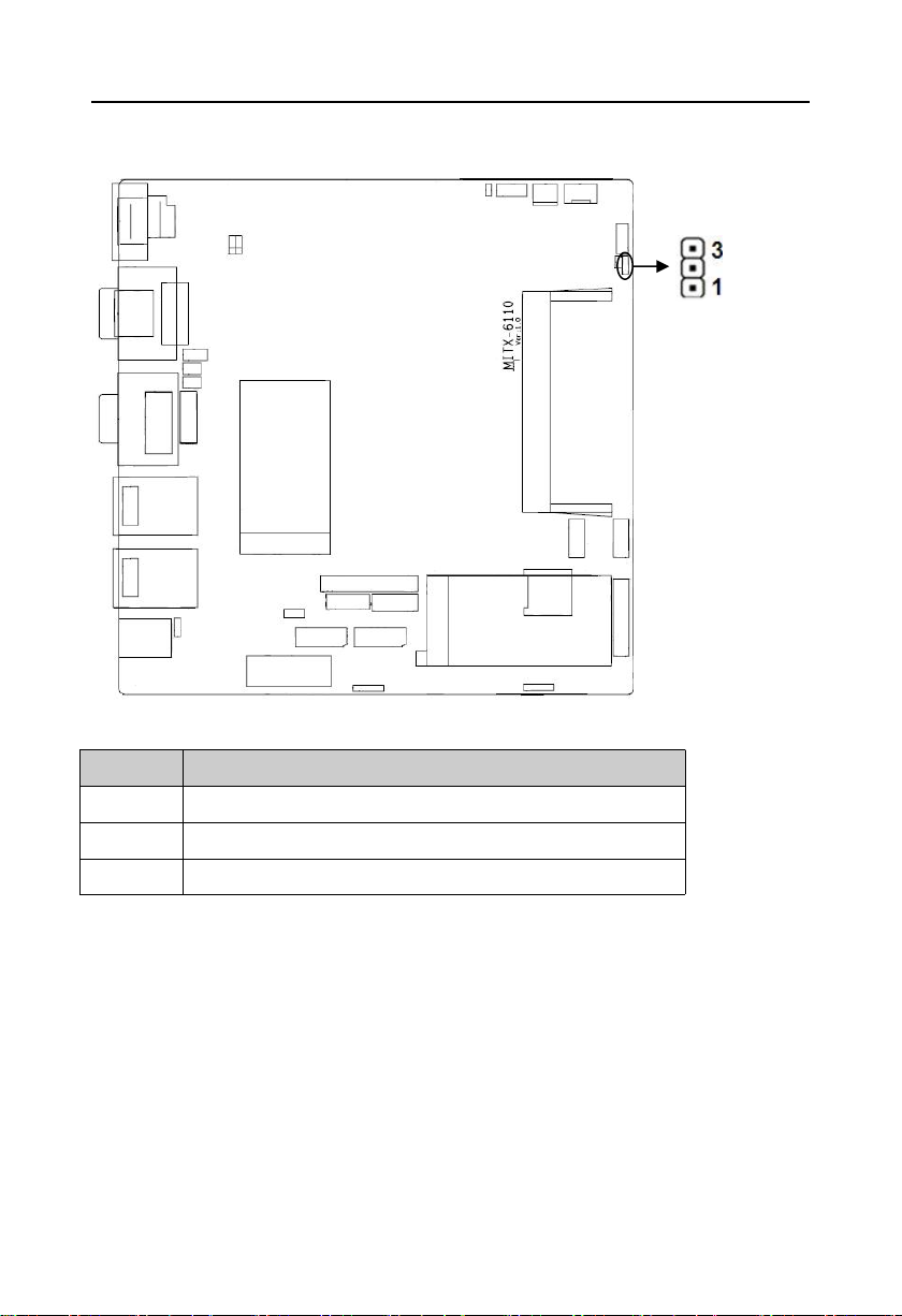
2.1 Interface Location and Dimension Diagram
The following picture is the interface index for MITX-6110. When you install your devices,
please consult it and read the following guide. During installation please care for some devices.
Improper installation will lead to system malfunctions.
Note:During installation, in order to protect the parts of the board, please put
on anti-static gloves.
MITX-6110 Interface Location and Dimension Diagram
2.2 Installation Steps
Please refer to the following steps to install your computer:
1.Adjust all Jumpers on MITX-6110 according to the manual;
3

MITX-6110 User's Manual
2.Install CPU and memory;
3.Install other expansion cards;
4.Connect all the signal lines, cable, panel-control circuitry and power supply;
5.Start the computer,finish BIOS setup.
Key components of this motherboard are Integrated circuit, and these components
will be easily damaged by electrostatic influence. So, before installing the motherboard,
you should always keep the following precautions in mind:
1.Hold the board by the edges; don't touch any components or pins on the board.
2.Use an anti-static wrist strap or wear anti-static gloves while getting in touch with integrated
circuit components (such as CPU, RAM).
3 . Place components in a grounded anti-static bag/pad when these components are
uninstalled.
4.Please make sure the power switch is disconnected before inserting the power plug.
2.3 Memory Installation
This motherboard is equipped with DDR4 slot. Please pay attention to the following two
points when installing memory bank:
1.When fixing, make sure the notch matches SO-DIMM socket and then insert memory bank
into the socket. Press it down to tight the connection.
2.Choose the proper memory bank that supports motherboard specification.
2.4 Jumper Setting
Please setup the jumpers accordingly before installing hardware devices.
Note: How to identify jumper and PIN1 of interface. Please observe the word mark of plug
socket, it will use “1” or bold line or triangular symbols; And please look at the back of PCB,
each weld spot has a square point, which is PIN 1; usually there is a white arrow beside PIN 1.
2.4.1 CMOS Content Clearance /Hold Setting(JCC1、JCC2)
CMOS powered by on board button battery. Clean CMOS will lead to a permanent
elimination of the previous system setting and back to the original (default setting) system
settings.
Steps:(1)Turn off the computer, disconnect the power supply;
(2)Use jumper cap short JCC Pin 1 and Pin 2 for 5~6 sec,Then restore the default
4

MITX-6110 User's Manual
Setting
JCC
1-2
Clear CMOS (BIOS renew to initialization)
2-3
Normal status(default)
JCC1、JCC2
setting of Pin 2 and Pin 3;
(3 )Turn on the computer, then press DEL key into the BIOS setting and reload the
optimized defaults;
(4)Save and exit setting.
JCC:
Do not clear CMOS when power on, otherwise it will damage the motherboard!
5

MITX-6110 User's Manual
Setting
JAT
Open
Disable Auto Boot
Close
Enable Auto Boot
JAT
2.4.2 Hardware Switch for System Auto Boot upon Power On (JAT)
JAT:
6
MITX-6110 User's Manual
PIN
SINGNAL NAME
1
UART2_TXD
2
GND
3
UART2_RXD
DB_UART
2.4.3 Debug Interface(DB_UART)
DB_UART:
2.4.4 COM2 Jumper Setting(J1,J2)
J1 , J2 jumper are used to set the transmission mode of COM2 , COM2 support
RS232/RS485 transmission mode,you can choose settings according to your own needs, the
default transmission mode is RS232.
7

MITX-6110 User's Manual
COM2 RS232(default)
COM2 RS485
J1
1-3 2-4
3-5 4-6
J2
1-2
3-4 5-6
J1、J2
J1、J2:
2.5 Interface Specification
When connecting external connectors, please read this manual carefully in order to
avoid damage to the motherboard!
2.5.1 SATA Port(SATA1、SATA2、JSATAPWR、MCU_DB)
Provide 2x7PIN SATA port,and 1x2.54mm 1X5PIN connector(SATApower supply)port,
1xMCU_DB port.
8

MITX-6110 User's Manual
PIN
SINGNAL NAME
1
GND
2
TX+
3
TX-
4
GND
5
RX-
6
RX+
7
GND
PIN
SINGNAL NAME
1
+12V
2
GND
3
+5V
SATA2
JSATAPWR
SATA1
MCU_DB
SATA1、SATA2:
JSATAPWR:
9

MITX-6110 User's Manual
4
GND
5
+3.3V
PIN
SINGNAL NAME
1
NC
2
MCU_TXD
3
MCU_RXD
4
MCU_RST#
5
GND
SINGNAL NAME
PIN
SINGNAL NAME
HDMI_COM2 JCOM1
VGA_COM2 JCOM2
JVGA
MCU_DB:
2.5.2 Serial Ports (HDMI JCOM1、VGA JCOM2)
Provide 2xstandard COM ports,COM1 support RS232 model,COM2 support RS232/485
model.
JCOM1:
10

HDCD#1
12HDSR#1
HSIN1
34HRTS#1
HSOUT1
56HCTS#1
HDTR#1
78HRI#1
GND
910GND
JCOM2:
SINGNAL NAME
PIN
SINGNAL NAME
HDCD#2TX-DATA-
12HDSR#2
HSIN2TX+DATA+
34HRTS#2
HSOUT2
56HCTS#2
HDTR#2
78HRI#2
GND
910GND
PIN
SINGNAL NAME
1
DATA-
2
DATA+
3
HSOUT2
4
HDTR#2
5
GND
6
HDSR#2
7
HRTS#2
8
HCTS#2
9
HRI#2
PIN
SINGNAL NAME
1
HDCD#1
2
HSIN1
3
HSOUT1
4
HDTR#1
5
GND
VGA_COM2:
MITX-6110 User's Manual
COM1:
11

MITX-6110 User's Manual
6
HDSR#1
7
HRTS#1
8
HCTS#1
9
HRI#1
SINGNAL NAME
PIN
SINGNAL NAME
VGA1_R
12GND
VGA1_G
34VGA1_SDA_R
VGA1_B
56VGA1_HSYNC
5V_DDC
78VGA1_VSYNC
GND
910VGA1_SCL_R
LVDS
JVGA:
2.5.3 Display Port(LVDS)
Provide 1xdual channel LVDS port.
12

LVDS:
SINGNAL NAME
PIN
SINGNAL NAME
VDD_PANEL
12VDD_PANEL
VDD_PANEL
34L_BKLTEN_R
GND
56GND
LVDSA_DATA0#
78LVDSA_DATA0
LVDSA_DATA1#
910LVDSA_DATA1
LVDSA_DATA2#
1112LVDSA_DATA2
GND
1314GND
LVDSA_CLK#
1516LVDSA_CLK
LVDSA_DATA3#
1718LVDSA_DATA3
LVDSB_DATA0#
1920LVDSB_DATA0
LVDSB_DATA1#
2122LVDSB_DATA1
LVDSB_DATA2#
2324LVDSB_DATA2
GND
2526GND
LVDSB_CLK#
2728LVDSB_CLK
LVDSB_DATA3#
2930LVDSB_DATA3
MITX-6110 User's Manual
13

MITX-6110 User's Manual
PIN
SINGNAL NAME
1
+3.3V
2
LVDS_VDD
3
+5V
PIN
SINGNAL NAME
1
GND
2
GND
3
LVDS_PWM_OUT_R
4
L_BKLTEN_R
5
VCC12_S
JLVDSPWR
JLVDS
JLVDSBTN
2.5.4 LVDS Voltage and Backlight Setting Interface (JLVDS、 JLVDSBTN、
JLVDSPWR)
JLVDS:
JLVDSPWR:
14

MITX-6110 User's Manual
6
VCC12_S
PIN
SINGNAL NAME
1
BLUP
2
GND
3
BLDN
4
GND
5
PWRDN
SINGNAL NAME
PIN
SINGNAL NAME
USB56 USB3_LAN1
USB78 USB_LAN2
USB12
USB34
JLVDSBTN:
2.5.5 USB Port(USB12、USB34、USB56_USB3_LAN1、USB78_USB_LAN2)
Provide 2x standard Gigabit RJ45 network interface and 8xUSB port;in which 4x standard
USB 2.0 port 、4 x standard USB3.0 port. RJ45 Ethernet interface has 1xLED on each side:
Yellow indicates data transmission status, green indicates network connection status.
USB12、USB34:
15

MITX-6110 User's Manual
VCC_USB5
12GND
USBD_N
34GND
USBD_P
56USBD_N
GND
78USBD_P
GND
910VCC_USB5
LILED(Green)
Function
ACTLED(Yellow)
Function
ON
100/1000M link
FLASH
Data transfer
FLASH
10M link or close
OFF
Data stop transferring
SINGNAL NAME
PIN
SINGNAL NAME
VCC_KBMS
12MS_CLK_R
KBMS
RJ45 LAN LED state descriptions:
2.5.6 Keyboard & Mouse Interface(KBMS)
One 2x4 Pin 2.0mm pin interface , converting to standard PS/2 keyboard and mouse
interface by switching wiring.
KBMS:
16

MITX-6110 User's Manual
GND
34MS_DATA_R
KB_DATA_R
56GND
KB_CLK_R
78VCC_KBMS
SINGNAL NAME
PIN
SINGNAL NAME
SIO_GPIO_135
12VCC3P3_A
SIO_GPIO_136
34SIO_GPIO_141
SIO_GPIO_139
56SIO_GPIO_143
SIO_GPIO_140
78SIO_GPIO_145
GND
910SIO_GPIO_146
JGP
2.5.7 Programmable I/O Interface(JGP)
One 2x5Pin 2.0mm pin 8bit GPIO interface,can be customized for input or output use.
JGP:
17

MITX-6110 User's Manual
PIN
SINGNAL NAME
1
+12V
2
GND
3
GND
PIN
SINGNAL NAME
1
GND
2
GND
3
+12V
4
+12V
PWR1-3
2.5.8 Power Interface(PWR1、PWR2、PWR3)
MITX-6110 motherboard provides 3xPWR power interface,supporting only one of three
choices.
External power interface PWR1、PWR3:
External power interface PWR2:
18

MITX-6110 User's Manual
PIN
SINGNAL NAME
1
GND
2
+12V
3
FANIN3
PIN
SINGNAL NAME
1
GND
CPU_FAN
CPU_FAN
2.5.9 Fan Interface(SYS_FAN、CPU_FAN)
1xSYS_FAN interface,1xCPU_FAN interface,two things to note when using fans:
(1) Fan current≤350 mA(4.2W,12V).
(2) Make sure that the fan wiring and the outlet wiring match. Power cord (usually red) is in
the middle. In addition, ground wire (usually black) and fan speed output pulse signal line (other
colors). Some fans have no speed detection, but the lead has up to 12V output, which will
damage the motherboard. It is recommended to use a fan with rotational speed detection.
SYS_FAN:
CPU_FAN:
19

MITX-6110 User's Manual
2
+12V
3
CPUFANIN
4
CPUFANOUT
PIN
SINGNAL NAME
1
LINE1*L
2
AGND
3
LINE1*R
LINE_IN
2.5.10 Line Input Pin(LINE_IN)
One 1x3PIN LINE_IN pin
LINE_IN:
2.5.11 JLPC Interface(JLPC)
One 2×10Pin 2.54mm JLPC interface,to expand external devices
20

MITX-6110 User's Manual
SINGNAL NAME
PIN
SINGNAL NAME
LPC_3V3_CLK1
1
2
GND
LPC_FRAME_3V3
34CLK_48M_2#
JLPC_RESET#
56VCC5_S_SIO
LPC_AD3
78LPC_AD2
VCC3P3_SIO
910LPC_AD1
LPC_AD0
1112GND
SMB_3P3_CLK
1314SMB_3P3_DAT
VCC3P3_A
1516LPC_SERIRQ_3V3
GND
17
18
NC
SUS_STAT
19
20
NC
JLPC
JLPC:
21

MITX-6110 User's Manual
AUDIO
2.5.12 Audio Port(Audio)
Provide 1xaudio port,green is Line-out,red is Mic-in.
22

MITX-6110 User's Manual
PIN
SINGNAL NAME
1
EMMC BOOT
2
GP_INTD_DSI_TE1
JMC
2.5.13 BIOS Write Protection Interface(JME)
JME:
2.5.14 Front Panel Interface (JFP)
Provide one 2×5Pin 2.54mm front panel pin. JFP is used to connect function buttons and
LED indicator on the front panel.
23

MITX-6110 User's Manual
SINGNAL NAME
PIN
SINGNAL NAME
PLED+
12GND-
HDD_LED+
34SATA_LED_N_R
VCC
56BUZZDATA#
RSTBTN_N_R
78GND
PWRBTN_N_R
910GND
POWER_LED
IDE_LED
BUZZ
RESET SW
POWER SW
JFP
JFP:
Please follow the table below to connect, pay attention to the anode (+) and cathode (-),
otherwise some function cannot be realized.
24

MITX-6110 User's Manual
1)System power LED pins(pin 1、pin 2 POWER_LED)
Connect system power LED cable with these pins.(pin 1 is LED anode)When system is
power on, power LED is on;when system is power off, power LED is off.
2)HDD LED Pins(pin 3、pin 4 HDD_LED)
Case panel comes with one HD LED indicating HD status. When HD read and writes, the
LED will flash, indicating the device is working. Connect the LED cable to the LED pins (Pin3 is
LED anode).
3)Buzzer Pins(pin 5、pin 6 SPEAKER)
External pin for speaker
4)Reset Button Pins(pin 7、pin 8 RESET SW)
Connect the reset button cable to these two pins. When system fails, reset button can
make the system continue to work and no need to turn on / off the power.
5)Power ON/OFF Pins(pin 9、pin 10 POWERSW)
Connect these two pins to the bounce switch on the chassis to connect or disconnect the power
supply.
2.5.15 Memory Slot (SO-DIMM)
On board with 1x single channel SO-DIMM slot,support DDR4 4/8GB up to 2400MT/s.
2.5.16 Expansion Interface(PCIE_X1、MINI_ PCIE1、MINI_ PCIE2)
On board with 1xstandard PCIE_X1 port,2 x standard MINI PCIe port and SIM card slot,
users can extend MINI PCIe device according to their own needs(default MSATA function).
25

Chapter
Three
BIOS
Set up

MITX-6110 User's Manual
25
Chapter Three BIOS Set up
AMI BIOS Refresh
BIOS functions as a bridge connecting hardware and operating system. Hardware and
software are upgrading all the time, so when your system goes wrong, for example, your
system cannot support the newest CPU, you need to upgrade BIOS to keep up with the latest
technology.
FPT.efi is a FLASH IC read and writes program loaded BIOS data on the motherboard. It must
be operated in shell environment.
Enter the pure shell environment to access the U disk, and then use the FPT. EFI program
to write the BIOS data you used to upgrade (such as **. bin) into FLASH IC.
Specific operation instructions are:
fpt.efi -f 6110****.bin
If you need to add other parameters after the order format, please add space/?
Note:
1.Upgrading BIOS is only executed when it is necessary.
2.Please use the BIOS SETUP programs in the CD-ROM provided by us or download the
latest version on related websites
3. Do not turn off the power or restart the system during the upgrade process, or your
BIOS data will be damaged and the system may not start.
4.When the refresh is complete, manual LOAD Default is needed to optimize.
5.To prevent any unexpected problems, please backup your BIOS in advance.
AMI BIOS Description
When the computer is power on, BIOS will conduct self-diagnosis to its hardware on
motherboard and configure hardware parameter; finally the operating system will take control.
BIOS is the bridge between hardware and software. How to set BIOS parameters correctly is
very important to the stability of the system and whether the system works in the best state.
BIOS Setting
1、Power on or restart the system, self-detection message will display on the screen.
2、 When the prompt "Press < DEL > to enter setup, < F11 > to Popup menu" appears in the
middle of the screen, press the < Del > key to enter the BIOS setup program.

MITX-6110 User's Manual
26
3、Use the “←↑→↓”to select the option which you want to modify, press <Enter> to go to the
sub-menu.
4、Use the “←↑→↓”and <Enter> to modify the value; press “ Enter” to modify BIOS options
that you choose.
5、At any time, press<Esc> can go back to the former menu.
3.1 Main Menu
BIOS Vendor :BIOS vendor,American Megatrends
BIOS Version :BIOS version,6110T108
Build Date and Time :BIOS date and time,12/24/2018 10:22:06
CPU Information :Supplier, model, information
Memory Information :Memory, frequency
System Date
System Date Format: Month/Day/Year. Setting scale is Month (Jan.-Dec.), Date (01-31),
Year (up to 2099), Week (Mon. ~ Sun.).
System Time

MITX-6110 User's Manual
27
System Time Format: Hour/Minute/Second. Setting scale is Hour (00-23), Minute (00-59),
Second (00-59).
3.2 Advanced
ACPI Settings
Setting system sleep depth S3
CPU Configuration
CPU configuration and common setting
SATA Drives
HDD mode settings and HDD information
USB Configuration
USB information and control option
F81804 Super IO Configuration
F81804 Super IO Configuration information, including COM interrupt number and
address settings
Hardware Monitor

MITX-6110 User's Manual
28
Hardware voltage detection information
Serial Port Console Redirection
Serial port redirection settings
LAN Configuration
LAN information and control options
Network Stack Configuration
Set whether to load on-board UEFI network card boot code
CSM Configuration
Compatibility support module control options
3.2.1 ACPI Settings
ACPI Sleep State
This item is used to select the power saving mode when the system is sleeping. If the
mode is different, the power consumption of the system is different. Suspend Disabled, turns off
sleeping model: S1(CPU Stop Clock):CPU stops working while other equipment are still power
up.

MITX-6110 User's Manual
29
3.2.2 CPU Configuration
Socket 0 CPU Information
This is the specific information for displaying the CPU
EIST
Intelligent frequency reduction technology switching on or off settings
Turbo Mode
Boot performance mode
Boot performance mode selection
C-States
CPU operating mode
Enhanced C-state
Enhanced Mode
Max Package C State
Max Core C State

MITX-6110 User's Manual
30
Read-only items contain CPU details, including CPU manufacturer, model, frequency, L1
Cache size, L2 Cache size, and so on.

31
3.2.3 SATA Drives
MITX-6110 User's Manual
SATA Drives
SATA controller
SATA Mode Selection
Setting up SATA configuration mode
SATA Test Mode
SATA Port 0
SATA Port 0 detected storage device
Port 0
Configure the opening and closing of SATA port 0
SATA Device Type
Setting up SATA device type
SATA Port 1
SATA Port 1 detection of storage devices
Port 1

MITX-6110 User's Manual
32
This configuration opens and closes SATA port 1
SATA Device Type
Setting up SATA device type
3.2.4 USB Configuration
Legacy USB Support
Legacy USB supports setting. To support USB devices in DOS mode, such as USB
FLASH disk, USB keyboard, select this option as [Enabled] or [Auto]. Otherwise, select
[Disabled].
XHCI Hand-off
To determine whether BIOS takes control of XHCI or not when operating system do not
support XHCI. Default: [Enabled].
EHCI Hand-off
This option is used to determine whether to plug the USB port into USB 2.0 mode before
entering OS. Setting it to [Disable] will operate in USB 1.1 compatible mode before handing
over ownership to OS.

MITX-6110 User's Manual
33
USB Mass Storage Driver Support
Mass USB storage on-off
USB Transfer time-out
Set USB device transfer command, data and time-out (default 20 seconds).
Device reset time-out
Set USB Devices reset time-out (default 20 seconds).
Device Power-up Delay
Set USB maxi device power-up delay.
Mass Storage Device
Set specific type for connecting USB devices, Set value: [Auto][Floppy][Forced
FDD][Hard Disk][CD-ROM], default: Auto.
3.2.5 F81804 Supper IO Configuration
Serial Port 1 Configuration
Serial Port 2 Configuration

MITX-6110 User's Manual
34

35
3.2.6 Hardware Monitor
MITX-6110 User's Manual
PC Health Status
This is used for hardware security detection; BIOS will display the current CPU
temperature, as well as other related voltage values. The above parameters have a certain
range, and the system cannot run beyond these ranges.
CPU temperature Current CPU temperature
System temperature Current system temperature
CPU 1 speed Current CPU1 Fan Speed
CPU 2 speed Current CPU2 Fan Speed
Vcore Current CPU Core Voltage
VCC5V Current 5.064 V Voltage
VCC3V Current 3.344 V Voltage
VSB3V Current 3.344 V Voltage
VBAT Current 3.248 V Voltage
MITX-6110 User's Manual
36
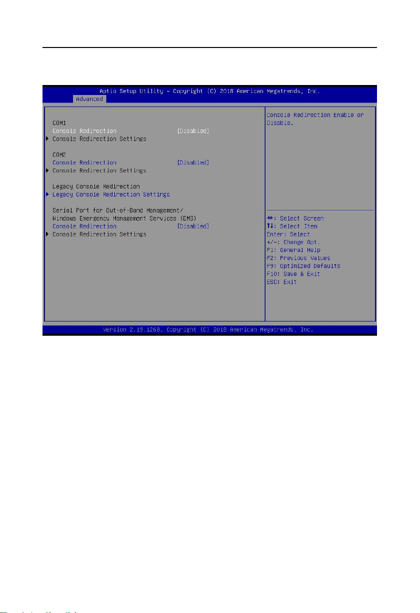
3.2.7 Serial Port Console Redirection
Console Reditection
Motherboard supports serial ports1, 2 console redirection, default Disable. Enable
console redirection just need to turn on COM1 or COM2 console redirection. EMS console
redirection is no need to be on.
Common options:
1. Console Redirection:Console switch options。
2. Terminal Type: VT100/VT100+/ VT-UTF8/ANSI. If terminal console character
scrambling needs to be adjusted, default: VT100+.
3. Bits per Second:Default: 115200

MITX-6110 User's Manual
37
3.2.8 LAN Configuration
Launch LAN1 PXE OpROM
Launch LAN2 PXE OpROM
Onboard LAN1 Controller
Onboard LAN2 Controller

MITX-6110 User's Manual
38
3.2.9 Network Stack Configuration
Network Stack

MITX-6110 User's Manual
39
3.2.10 CSM Configuration
CSM Support
CSM----Compatibity Support Module,belonging to UEFI. Provide compatibility support for
those not support UEFI system.
GateA20 Active
Option ROM Messages
To set OpROM display model
Interrupt 19 Capture
HDD Connection Order
Boot opdtion fildter
To set Efi OpROM and Legacy OpROM priority
Network
Choose to support which type of OpROM,like Efi OpROM or Legacy OpROM,support both.

MITX-6110 User's Manual
40
Storage
Choose to support which type of storage OpROM,like Efi OpROM or Legacy OpROM,support
both.
Video
Choose to support which type of display OpROM,like Efi OpROM or Legacy OpROM,
support both.
Other PCI devices
Other PCI devices OpROM implantation strategy
3.3 Chipset Menu
North Bridge
North Bridge Configuration Options. Options include display memory, display device, etc.
South Bridge
South Bridge Configuration Options. Including sound card, network card, auto boot upon
power on and other options.

41
3.3.1 North Bridge
MITX-6110 User's Manual
VBT Select
Primary IGFX Boot Display
Setting up main display device in integrated display card
LCD Panel Type
This is to set the resolution of the LVDS screen.

42
3.3.2 South Bridge
MITX-6110 User's Manual
PCI CLOCK RUN
Restore AC Power Loss
This item is used to set the boot-up situation after power-up. When power Off is selected,
the power button is pressed to boot up. When power On is selected, the boot-up will be started
directly after power-up. When last state is selected, the power-up will be restored to the state
before power-down.
Wake on LAN
To set whether Wake on LAN is allowed. The setting value is [Enabled][Disabled].
PCI Express Configuration
XHCI Pre-Boot Driver
XHCI Mode

MITX-6110 User's Manual
43
3.3.2.1 PCI Express Configuration
PCI Express Clock Gating
Port8xh Decode
Switch item decoding 80 ports to PCIE
Peer Memory write Enable
Peer memory write function
Compliance Mode
Standard compatibility mode
PCI Express Root Port 1/2/3/4/5/6
PCIE Root port

MITX-6110 User's Manual
44

MITX-6110 User's Manual
45

MITX-6110 User's Manual
46

47
3.4 Boot Menu
MITX-6110 User's Manual
Fast Boot
VGA Support
USB Support
Network Stack Driver Support
Boot up Numlock State
This function allows users to activate Numlock function when boot up.
[ON]: Numlock is activated when system boots up
[OFF]: Numlock under cursor control.
Quiet Boot
Boot Option #1/#2/#3

MITX-6110 User's Manual
48
The system will test the device in the set order until it finds a device that can be started and
then starts from the device. Among the startup options, # 1 is the most preferred startup device.
Hard Drive BBS Priorities
This item contains hard disks that can be used as boot devices. If there are multiple hard
disks, you should select the priority of these disks in this item. The top priority hard disks will be
displayed in Boot Option #1.
3.5 Security Menu
Password should within the following length:
Mininum:1. Maxium:20.
Administrator Password
Set administrator password.
User Password
Set User’s Password.

49
3.6 Exit Menu
MITX-6110 User's Manual
Discard Changes and Exit
Discard all changes and exit, and continue reboot.
Save Changes and Reset
Save all BIOS changes and exit, then reboot
Discard Changes and Reset
Quit changes and exit, then reboot
Save Options
Restore Defaults
Restore to default options
Save Changes
Discard Changes
Do not save modifications
Boot Override
Choose the specified Boot devices, like SATA,USB,EFI Shell,PXE,and etc. Boot, and
exit without save. Press <Enter> to choose specified Boot devices.

Appendix

MITX-6110 User's Manual
38
Appendix
Appendix 1 :Watchdog Programming Guide
watchdog reference code(ASM)
--------------------------------------------------------------------------------------------------------------
Set the port to realize watchdog function through operating ports by writing data to
corresponding ports, so that it can carry out Watchdog Timer’s various functions.
Port specification:
void main()
{
intindexp = 0x2e,datap = 0x2f;
unsigned char temp;
outportb(indexp,0x87);
outportb(indexp,0x01);
outportb(indexp,0x55);
outportb(indexp,0x55); //unlock
outportb(indexp,0x20);
temp = (unsigned char)inportb(datap);
if(temp!=0x87)
{
indexp = 0x4e,datap = 0x4f;
outportb(indexp,0x87);
outportb(indexp,0x01);
outportb(indexp,0x55);
outportb(indexp,0x55); //unlock
}
outportb(indexp,0x07);
outportb(datap,0x07); //enable logical device
outportb(indexp,0x74);

MITX-6110 User's Manual
39
outportb(datap,0x00);
outportb(indexp,0x72);
outportb(datap,0x80); //set second
outportb(indexp,0x73);
outportb(datap,0x03); //set 3 seconds
outportb(indexp,0xf3);
outportb(datap,0x00); //WDT’’s IRQ
outportb(indexp,0xf1);
outportb(datap,0x44); //wdt enable generate smi,and level trigger
outportb(indexp,0xf4);
outportb(datap,0x1e); //gpio36 mapping table
outportb(indexp,0x71);
outportb(datap,0x00);
outportb(indexp,0x27);
outportb(datap,0x40);
outportb(indexp,0x02);
outportb(datap,0x02); //exit
}

MITX-6110 User's Manual
40
Priority
Interrupt#
Interrupt source
1
NMI
Parity error detected
2
00
System timer
3
01
Available
-
02
Interrupt from controller 2 (cascade)
4
08
System CMOS/real time clock
5
09
Microsoft ACPI-Compliant System
6
10
Available
7
11
Communication port (COM3,4,5,6)
8
12
Available
9
13
Numeric data processor
10
14
Available
11
15
Available
12
03
Communication port (COM2)
13
04
Communication port (COM1)
14
05
Available
15
06
Available
1607Intel(R) N10/ICH7 Family SMBus Controller – 27DA
Addr. range
Device
00000000 – 00003FFF
Motherboard resources
000A0000 – 0000BFFF
Intel(R) Corporation Atom? N2000/D2000 Series Embedded
Media and Graphics Driver
000C0000 – 000DFFFF
PCI bus
000E0000 – 000EFFFF
PCI bus
000F0000 – 000FFFFF
PCI bus
CF800000 – CFFFFFFF
PCI bus
D0000000 – FEBFFFFF
PCI bus
DFC00000 – DFCFFFFF
Intel Corporation Atom? N2000/D2000 Series Embedded Midia
Appendix 2:IRQ and System Memory Map,1st MB Memory Map
IRQ:
System Memory Map:

MITX-6110 User's Manual
41
and Graphics Driver
DFD00000 – DFD03FFF
Realtek PCIe GBE Familly Controller
DFD00000 – DFDFFFFF
Intel (R) N10/ICH7 Family PCI Express Root Port – 27D2
DFD04000 – DFD04FFF
Realtek PCIe GBE Familly Controller
DFE00000 – DFE03FFF
Realtek PCIe GBE Familly Controller #2
DFE00000 – DFEFFFFF
Intel (R) N10/ICH7 Family PCI Express Root Port – 27D0
DFE04000 – DFE04FFF
Realtek PCIe GBE Familly Controller #2
DFF00000 – DFF03FFF
Microsoft Used in High Definition Audio UAA Bus Driver
DFF04000 – DFF043FF
Intel (R) N10/ICH7 Family Serial ATA Storage Controller –
DFF05000 – DFF053FF
Intel (R) N10/ICH7 Family USB2 Enhanced Host Controller
–27CC
E0000000 – EFFFFFFF
System board
FEC00000 – FEC00FFF
Motherboard resources
FED00000 – FED003FF
High precision event timer
FED14000 – FED19FFF
System board
FED1C000 – FED1FFFF
Motherboard resources
FED1C000 – FED1FFFF
Motherboard resources
FED20000 – FED8FFFF
Motherboard resources
FED45000 – FED8FFFF
Motherboard resources
FEE00000 – FEE00FFF
Motherboard resources
FF000000 – FFFFFFFF
Intel (R) 82802 Firmware Hub Device
FF000000 – FFFFFFFF
Intel (R) 82802 Firmware Hub Device
FFE00000 – FFFFFFFF
Motherboard resources

MITX-6110 User's Manual
42
Appendix 3:Glossary
ACPI
Advanced Configuration and Power Management. ACPI specifications allow operating system
to control most power of the computer and its add-on.
BIOS
Basic Input/Output System. It is software including all in/out control code interface in PC. The
software will detect hardware when it auto boot, operate OS, and provide an interface between
OS and hardware. BIOS is stored in a ROM chip.
BUS
BUS is a channel for different devices to exchange data in computer system. It is hardware
circuit. BUS here refers to partial lines inside CPU and the main components of system
memory.
Chipset
Chipset is an integrated set of chips for executing one or more related functions。Here it refers
to a system level chipset structured by South bridge & North bridge; Chipset decides the
structure and main functions of motherboard.
CMOS
Complementary Metal-Oxide Semiconductor, which is a widely used semiconductor with the
characteristics of high-speed and low-power consumption. COMS here refer to part of space
on-board CMOS RAM for saving date, time, system information and system parameter setting
information, etc.
COM
Cluster Communication Port. A universal serial communication interface, usually adopts
normative DB 9 connector.
DIMM
Dual-Inline-Memory-Modules. It is a small circuit board with memory chipset providing 64 bit

MITX-6110 User's Manual
43
memory bus width.
DRAM
Dynamic Random Access Memory. It’s a general type of memory for regular computer which
usually store 1 bit with a transistor and a capacitance. With the development of the technology,
more and more types of DRAM with different specifications exist in computer applications. For
example: SDRAM/DDR SDRAM/RDRAM.
I2C
Inter-Integrated Circuit Bus is a two-wire serial bus developed by PHILIPS company, which is
used to connect microcontroller and its peripheral equipment.
LAN
Local Area Network. Network grouped by correlative computers in a small area, generally in a
company or a building. Local area network is buildup by sever, workstation, some
communications links. Terminals can access data and devices anywhere through cables, which
enables users to share costly devices and resource.
LED
Light-Emitting Diode. A semiconductor device that lighted when power supply is connected, it is
often used to indicate information directly, for example, to indicate power on or HDD working
normally.
PnP
It is a specification that allows PC to configure its external devices automatically and it works
independently without the manual operation. To achieve this function, BIOS should be able to
support PnP and a PnP expansion card is also necessary.
POST
Power On Self Test. While the system is booting, BIOS will keep testing the system which
including RAM, keyboard, hard disk driver to check if all the components are connected directly
and function well.

MITX-6110 User's Manual
44
PS/2
A keyboard & mouse connective interface specification developed by IBM. PS/2 is a DIN
interface with only 6PIN; it also can connect other devices, like modem.
USB
It is the Universal Serial Bus for short. A hardware interface adapts to low speed peripherals,
and is always used to connect keyboard, mouse etc. One PC can connect maximum 127 USB
devices, providing 12Mbit/s transmit bandwidth USB supports hot swap and multi-data stream,
namely, you can plug USB devices while system is running, system can auto-detect and makes
it work on.

 Loading...