

Page 1

EMB-4850
EPIC Embedded Board
USER' Manual V1.2
Page 2

Headquarter (China):86-0755-27331166
Shenzhen:86-0755-27331166
Beijing:86-010-82671166
Shanghai:86-021-61212088
Chengdu:86-028-85259319
Nanjing: 025-58015489
Shenyang:86-024-23960846
Xi’an:86-029-88338386
Wuhan:86-027-87858983
TianJin:86-022-23727100
Singapore:65-68530809
Website:www.norco.com.cn
EMB-4850
EPIC Embedded Board
USER' Manual V1.2
Page 3

EMB-4850 EPIC Embedded Board
Place/Data: HONG KONG/2008
Shenzhen NORCO Intelligent Technology Co.,Ltd.
Shenzhen NORCO Intelligent Technology Co.,Ltd.
Page 4

Data: 2008
Trade Name:Shenzhen NORCO Intelligent Technology Co.,Ltd.
Model Name:EMB-4850
Responsible Party:Shenzhen NORCO Intelligent Technology Co.,Ltd.
Equipment Classification:FCC Class B Subassembly
Type of Product:EPIC Embedded Board
Manufacturer:Shenzhen NORCO Intelligent Technology Co.,Ltd.
Page 5

Content
Chapter1 General Information ................................................................................................ 1
1.1 Introduction ................................................................................................................. 1
1.2 Ordering Information................................................................................................... 1
1.3 Environmental and Dimensions .................................................................................. 1
1.4 Specifications..............................................................................................................1
Chapter 2 H/W Installation....................................................................................................... 3
2.1 Connector Locations................................................................................................... 3
2.2 Dimensions ................................................................................................................. 4
2.3 Installation step...........................................................................................................5
2.4 CPU & Cooling Fan Installation .................................................................................. 5
2.5 Jumper settings .......................................................................................................... 6
2.5.1 CMOS Clear (JCC) .................................................................................................. 6
2.5.2 Virus-Avoided Jumper (JAV) ................................................................................... 7
2.5.3 COM2 setting(J7、J8、J9)...................................................................................... 8
2.5.4 PC104+ select voltage setting (J5).......................................................................... 9
2.6 External Connector ................................................................................................... 10
2.6.1 mini IDE Connector(J12)................................................................................... 10
2.6.2 Parallel Port Connector(J13)............................................................................. 11
2.6.3 Serial port Connector(CONN1、COM2)........................................................... 12
2.6.4 Display Connector(VGA1、LVDS1 、J3、J2) ........................................................ 13
2.6.5 USB Connector (USB1、CN1) ..............................................................................15
2.6.6 SATA Connector (SATA1、SATA2)........................................................................ 16
2.6.7 IrDA(IRDA)............................................................................................................. 17
2.6.8 Audio Connector(J11) ............................................................................................ 18
2.6.9 CPU FAN Connector (CPUFAN)............................................................................ 19
2.6.10 Power Connector (JP2) ....................................................................................... 19
2.6.11 Ethernet Connector (LAN1、LAN2) .................................................................. 20
2.6.12 PS/2 KB/MS connector(KBM1)............................................................................ 21
2.6.13 Front Panel Connector (J10) ............................................................................... 21
2.6.14 PC/104+............................................................................................................... 23
2.6.15 GPIO (J6)............................................................................................................. 24
Page 6

2.6.16 System Memory................................................................................................... 25
Chapter 3 BIOS Setep............................................................................................................ 27
3.1 Main Menu ................................................................................................................ 28
3.2 Advanced Menu ........................................................................................................ 29
3.2.1 CPU Configuration................................................................................................. 30
3.2.2 IDE Configuration .................................................................................................. 31
3.2.3 SupperIO Configuration ......................................................................................... 33
3.2.4 Hardware Health Configuration ............................................................................. 34
3.2.5 ACPI Configuration ................................................................................................ 35
3.2.6 APM configuration.................................................................................................. 36
3.2.7 Intel AMT Configuration .........................................................................................38
3.2.8 MPS Configuration................................................................................................. 39
3.2.9 PCI Express Configuration .................................................................................... 40
3.2.10 Smbios Configuration .......................................................................................... 41
3.2.11 Remote Access Configuration.............................................................................. 42
3.2.12 USB Configuration ............................................................................................... 43
3.3 PCIPNP .................................................................................................................... 45
3.4 Boot Menu ................................................................................................................ 46
3.4.1 Boot Settings Configuration ................................................................................... 47
3.4.2 Boot Device Priority ............................................................................................... 49
3.4.3 Hard Disk Driver .................................................................................................... 50
3.5 Security Menu........................................................................................................... 51
3.6 Chipset Menu............................................................................................................ 52
3.6.1 North Bridge Configuration ....................................................................................53
3.6.2 South Bridge Configuration.................................................................................... 54
3.6.3 Video Function Configuration ................................................................................ 55
3.7 Exit Menu.................................................................................................................. 57
Appendix................................................................................................................................. 58
Appendix 1: Driver Installation ........................................................................................ 58
Appendix 2:Watchdog programmer guide.................................................................... 59
Appendix 3: Glossary...................................................................................................... 61
Page 7

Copyright
With the exception of showing the accessories of product configuration, This manual do
not create any commitment of our company. We retained the rights to change it without prior
notice. We will not be responsible for any installation, the result of improper use of direct,
indirect, intentional or unintentional damage or hidden dangers.
Before buying products, please learn about product performance from the seller to see if it
is in line with your needs. NORCO is a registered trademark of Shenzhen NORCO Intelligent
Technology CO., LTD. Other trademarks involved in this manual, their ownership are owned by
its respective owners. The contents of this manual are protected by copyright law. All rights are
strictly reserved. Any form of unauthorized reproduction including but not limited to carbon copy,
facsimile transmission and electronic copy or email should be destroyed immediately.
Page 8

Common Sense in Safety Application
1. Before using this product, be sure to read carefully this user’s manual;
2. Any plate cards not ready to be installed shall be kept in the anti-static protective bags;
3. Before taking out the plate cards from the anti-static protective bags, first place hands on the
grounding metal object for a while (e.g. 10 seconds) so as to release static electricity in body
and hands;
4. While fetching plate cards, you should wear static protective gloves and have the habit of
contacting brims of them;
5. In order to prevent bodily electric shock or damage to products, first turn off the AC power or
unplug the power cord out of power sockets while inserting main boards or plate cards or
configuring again;
6. Before it is necessary to move plate cards or the unit, be sure to unplug the AC power cords
out of the power sockets;
7. Be sure to unplug AC power cords when there is an increase/decrease in plate cards for this
product;
8. Before you connect or unplug any equipment, be sure to determine whether all power cords
are unplugged in advance;
9. To prevent any unnecessary injuries to products due to frequent power on/off to the products,
after the unit is shut down, you must wait at least 30 seconds before you restart up the unit.
10: If anything unexpected exists during Equipment used, please contact the professionals.
Page 9

Packing List
Thank you very much for choosing our products. Please check your package completely
as the following item checklist first, if you find any components lost or damaged, please contact
your retailer.
■ EMB-4850 Mainboard
■User’s Manual
■driver CD
■jumper header
■ VGA cable
■ Parallel Port cable
■ Serial port cable
■ Double USB cable
■ SATA cable
■ IDE cable
■ Audio cable
1pcs
1 pcs
1 pcs
1bag
1 pcs
1 pcs
1 pcs
1 pcs
2 pcs
1 pcs
1pcs
Page 10

Chapter 1
General Information
Page 11

EMB-4850
EPIC Embedded Board
1
Chapter1 General Information
1.1 Introduction
The EMB-4850 is an EPIC Embedded industry motherboard with a high performance
based on Intel Core Duo processors. The EMB-4850, in conjunction with Intel 945GM+ICH7M
chipset, support Intel core Duo processor, 533/667MHz Font Side Bus. Support for dual
channel DDR2 667MHz memory technology, capacity up to 2GB;integrated Intel GMA 950
graphic controller, support VGA、LVDS 、TV-OUT Display output mode, VGA+LVDS and
TVOUT+LVDS dual independent display; supply 1 Mini-IDE interface,1 AUDIO interface,1
parallel interface,2 Serial ports(COM2 support RS232/422/485 mode);2 SATAⅡ ports;4 USB
2.0 Ports(supply ESD protect);2 1000/MB Ethernet interface. It also provides with other
advanced functions, IrDA,WatchdogTimer,PC/104+ extend function and GPIO function (8Bit
Input/Output).EMB-4850 with EPIC spec can provide the most advanced design of volume and
function. It can work without fans. Provide the perfect solution for your built-in application.
1.2 Ordering Information
Model Number Description
EMB-4850
EPIC Embedded Industry Board with
VGA/LVDS/TV-OUT/2LAN/2COM/LPT/AUIDO/GPIO
1.3 Environmental and Dimensions
Operating Environmental
Temperature:0~60℃
Humidity: 5%~95%
Dimensions
115mm×165mm (W×H)
1.4 Specifications
1) EPIC Embedded Industry Motherboard
Page 12

EMB-4850
EPIC Embedded Board
2
2) Support FSB with 533/800MHz Intel® Core Duo Processors(Socket 479)
3) Chipset: Intel® 945GM+ICH7M
4) Memory: support dual channel 200-pin SO-DIMM slot, memory up to 2GB (DDR 533/667)Ⅱ
5) BIOS:4M bit Flash BIOS, ACPI power management support
6) Watchdog Timer: 256 levels, 1 (s/m) programmable, timeout interrupt or system reset
7)Graphic Display: Intel945GM integrated Graphic controller, memory size optimized Shared
Memory architecture, support up to 224MB frame buffer using system memory. Support
VGA/LVDS/TV-OUT, VGA+LVDS and TVOUT+LVDS dual independent display
8) Expansion slot: 1x PC/104+ slot
9) IDE Controller: Standard mini IDE Interface
10) SATAⅡ Interface: 2 SATAⅡ Interface, data transmission speed up to 300MB/s
11) LAN: 2x1000Mbps Ethernet Interface, REALTEK 8111B Network chipset, 2×RJ-45
12) USB: Motherboard provide a standard dual-layer USB port and a set of 2×5 header USB
ports, which both support USB 2.0 at a high speed of 480Mbps.
13) Audio: Realtek ALC888 Audio, Support 7.1 channels HD audio output
14) Support IrDA transfers
15) I/0 Interface: Winbond W83627HF I/0 chipset, on board provide 1 Parallel port、2 serial
ports(COM1->RS232,COM2->RS232 /RS422/RS485,Supply ESD protect)、1 IrDA Port 、
1PS/2 keyboard/mouse interface
16) Power supply: +12V single power supply
17) GPIO: 8Bit Input/Output
Page 13

Chapter2
Product Installation
Page 14
EMB-4850 EPIC Embedded board
3
Chapter 2 H/W Installation
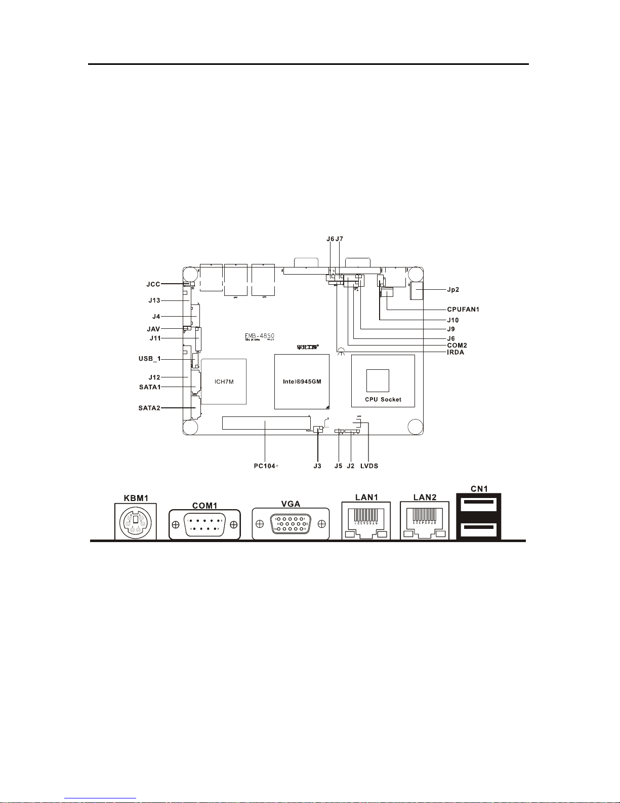
2.1 Connector Locations
The following picture is interface index for MITX-6852, when you install your devices,
please consult it and read the following guide. During installation please care: for some devices,
if incorrectly install, it will not work normally.
Notice:During installation, in order to protect the part of board, please put on antistatic gloves。
Page 15
EMB-4850 EPIC Embedded board
4
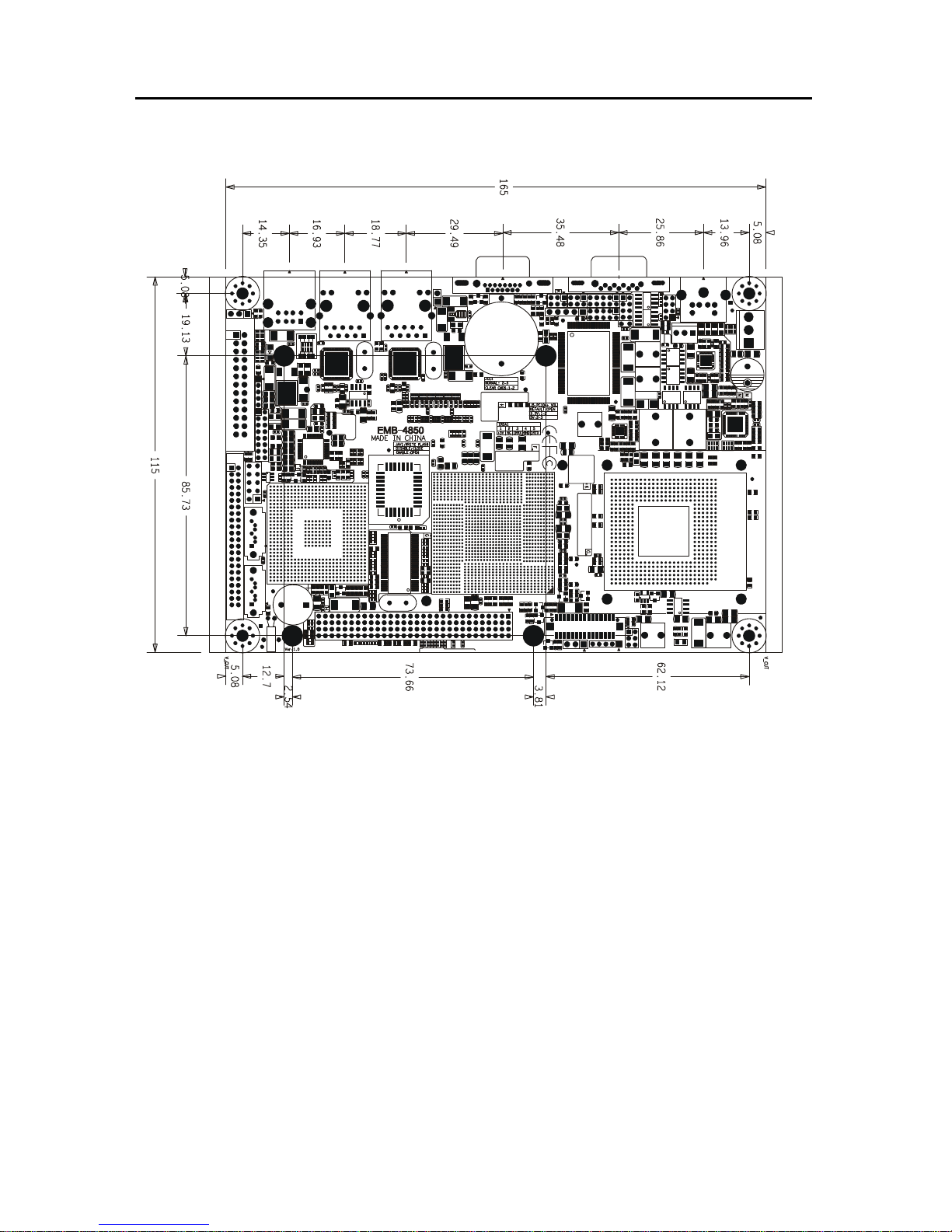
2.2 Dimensions
Page 16
EMB-4850 EPIC Embedded board
5
2.3 Installation step
Please consult the following step to install your computer:
1: Adjust all jumpers on the EMB-4850 per this manual
2: Install CPU
3: Install memory
4: Install Expand card (PC/104+ card)
5: Connect all of the signal line, cable, panel-control circuitry and power supply
6. Boot computer, Finish BIOS setup
Remind!Key components of this motherboard are Integrated circuit, and these components will
be easily damaged by electrostatic influence. So, before installing motherboard, you should
always follow the following precautions:
1. Disconnect your Computer from the power supply before handling it.
2. Hold side by the edges, don't touch any components or pins on the board
3. Use a grounded wrist strap while getting in touch with integrated circuit component (such as
CPU, RAM).
4. Place components on a grounded antistatic bag that came with the Single Board Computer,
when these components are separated from the system.
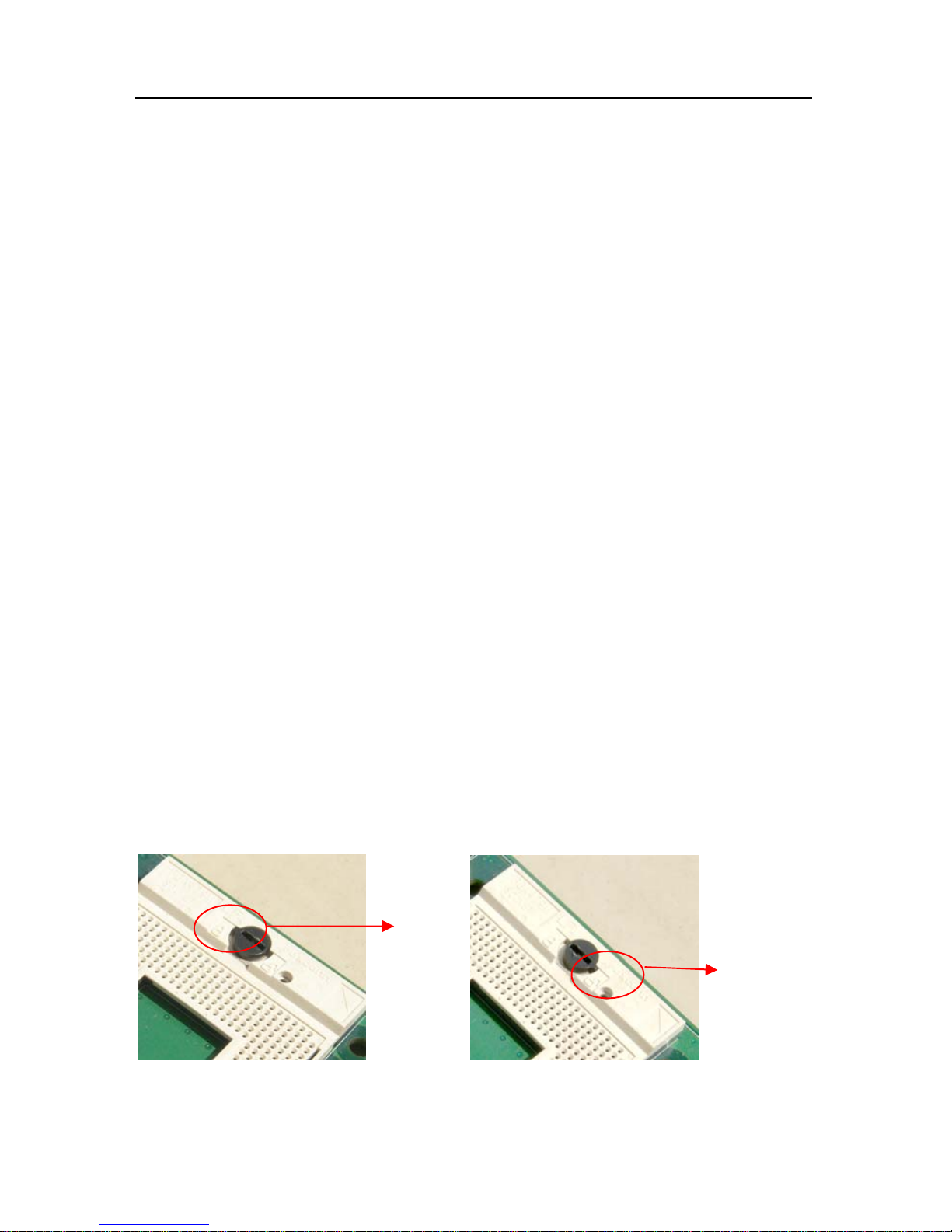
2.4 CPU & Cooling Fan Installa tion
Installing CPU complied following steps:
1: Twist the screws above the CPU socket with a screwdriver, and turn this pointer on screw
aimed at "Open" from the "Locked" position.
2: Hold the CPU by both sides, adjust the 1st pin (Marked as golden triangle) to be align with
the "missing" pin, then put the CPU in place. Check and adjust the CPU until it lays on the
Locked
Open
Page 17

EMB-4850 EPIC Embedded board
6
socket paralleled, then twist the pointer on screw aimed at "Locked" from the "Open" position.。
Notice:Ensure this motherboard support the CPU you choose, if the direction you inserted was
wrong, CPU may be damaged. After system boot, BIOS will examine CPU type and frequency
automatically, BIOS setting won’t allow you change the CPU frequency, in order to make
system work steadily, please set your CPU exterior frequency by its specification, and we don’t
suggest you over clock your CPU. At present most Intel ® CPU frequency multiplication have
been set when them leave factory, can not be changed.
Install CPU cooling fan complied steps following:
1. Fix the heat sink go with fan on motherboard, keep heat sink & CPU wafer tangent.
2. Connect fan cable with on-board CPUFAN socket.
Notice:
Before fixing, daub coolant on the surface of the heat sink connect CPU first to swell the
cooling function, check CPU work on or not regularity, to insure the CPU in good ventilate
situation.
2.5 Jumper settings
* Note:
Jumpers are located on the motherboard, they represent clear CMOS jumper JCC etc.
pin1 for all jumpers are located on the side with a thick white line refer to the motherboard’s
silkscreen , jumpers with three pins will be shown as 1-2 to represent pin1&pin2 connected and
2-3 to represent pin2&pin3 connected.
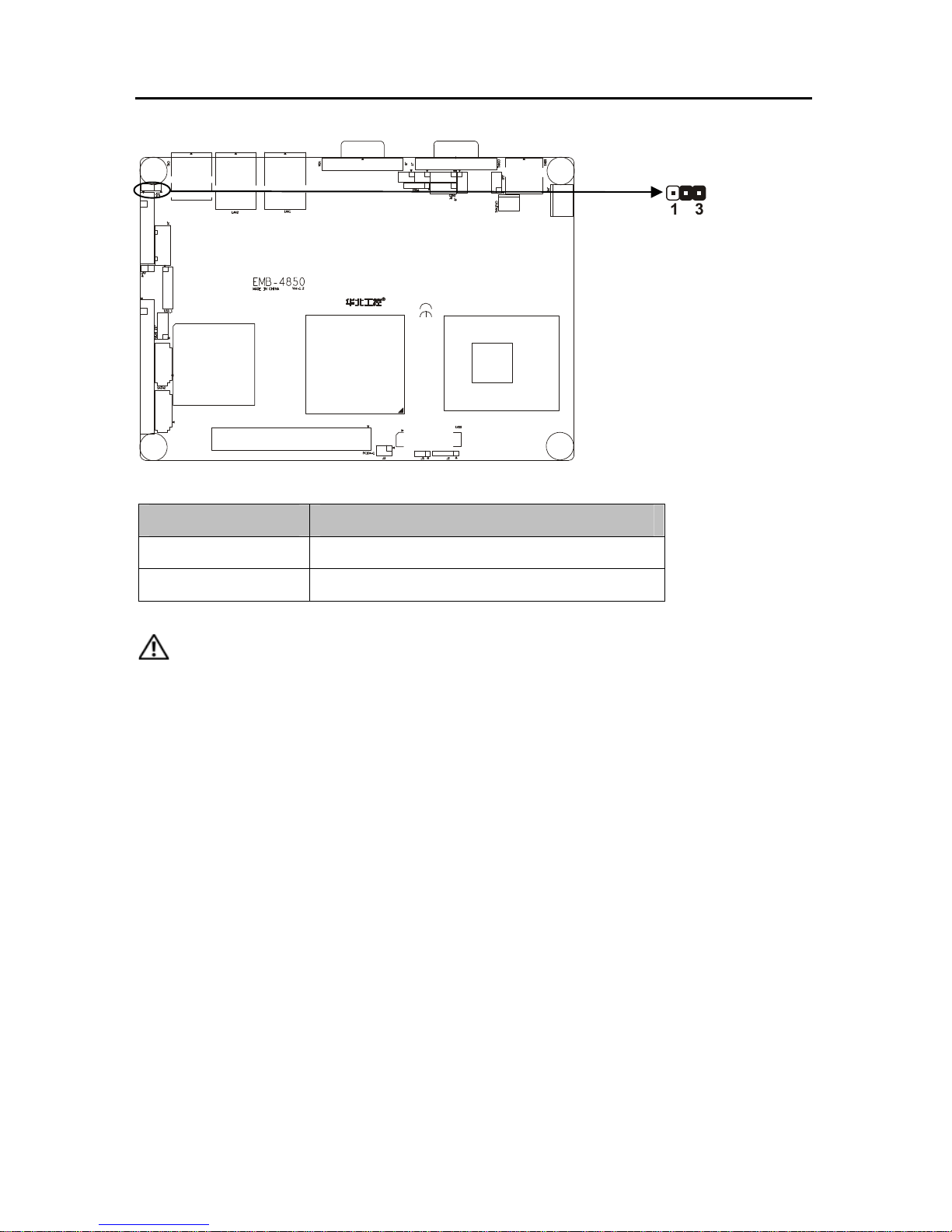
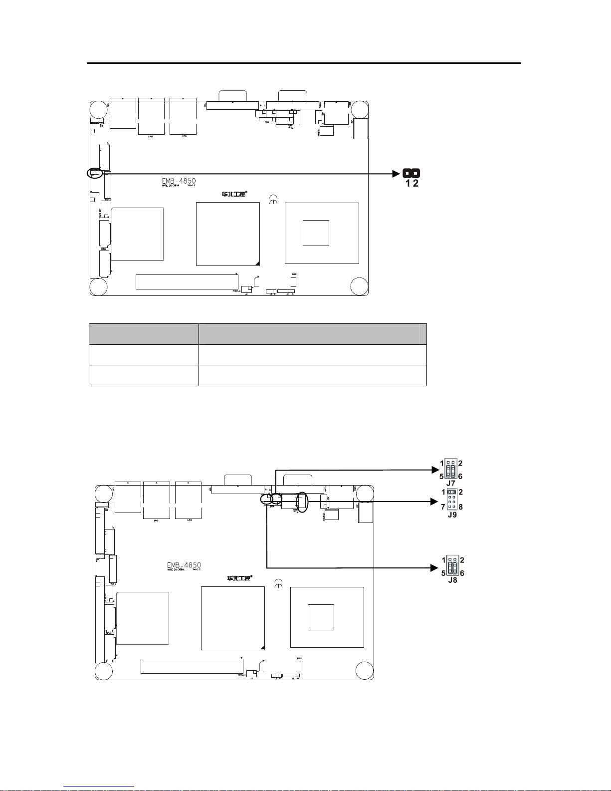
2.5.1 CMOS Clear (JCC)
This jumper is used to erase CMOS data and reset system BIOS information.
The procedure for clearing CMOS is:
1. Turn off the system.
2. Push clear CMOS button and wait for 4 second.
3. Turn on the system. The BIOS is now reset to its default setting
Page 18
EMB-4850 EPIC Embedded board
7
Setting JCC:
Setting JCC1
2-3
Normal(default)
1-2
Clear
Do not clear CMOS when power on, it harm to the motherboard.
2.5.2 Virus-Avoided Jumper (JAV)
The BIOS is contained inside the Flash ROM. If the jumper JAV is set as dosed, you can
not upgrade the BIOS. However in this status, the system BIOS can avoid being attacked by
virus, such as CIH virus.
Page 19
EMB-4850 EPIC Embedded board
8
Setting JAV:
Setting JAV1
Open Update BIOS
Close
BIOS write-protect(default)
2.5.3 COM2 setting(J7、J8、J9)
COM2 can be configured to operate in RS-232, RS-422, or RS-485 mode (RS232 for
default.). This is done via J7、J8 and J9.
Page 20
EMB-4850 EPIC Embedded board
9
Mode J7 J8 J9
RS232
3-5,4-6 3-5,4-6 1-2
RS422
1-3,2-4 1-3,2-4 3-4
RS485
1-3,2-4 1-3,2-4 5-6,7-8
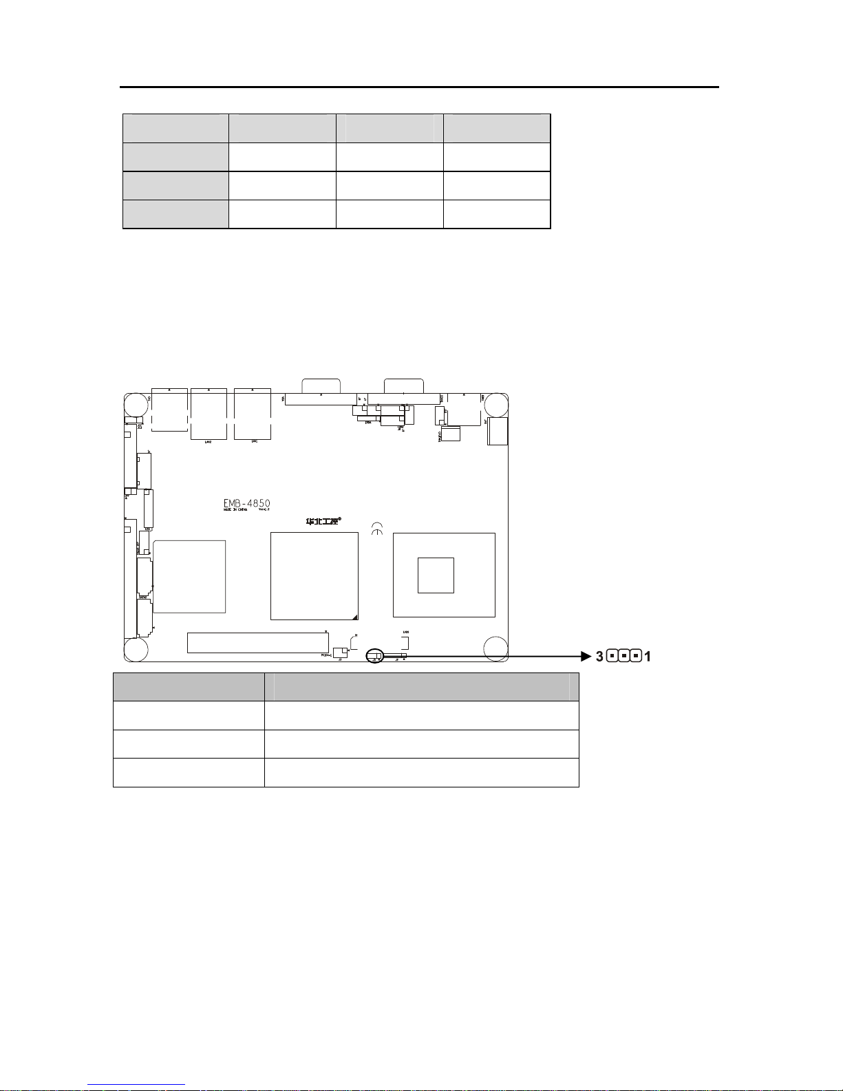
2.5.4 PC104+ select voltage setting (J5)
1 standard PC104+ expansion slot, the user may act according to own demand to choose
the different PC/104+ expansion module, the different module input voltage is dissimilar, you
may through jump the line to the PC/104+ module voltage to carry on the select
Setting J5
Open default
1-2 3.3V
2-3 5V
Page 21
EMB-4850 EPIC Embedded board
10
2.6 External Connector
Please carefully read this manual when connecting external connector, so as to avoid
damage to the motherboard!
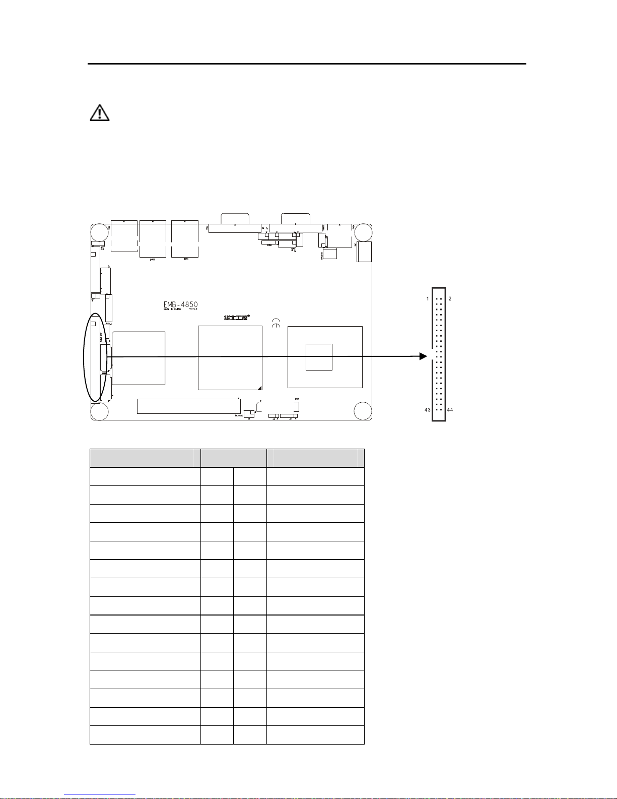
2.6.1 mini IDE Connector(J12)
The board provides 1 mini IDE channel to which you can attach up to two Enhanced
Integrated Device Electronics hard disk drives or CDROM to the board’s internal controller.
J12:
Signal name Pin Signal name
RESET# 1 2 GND
DDP7 3 4 DDP8
DDP6 5 6 DDP9
DDP5 7 8 DDP10
DDP4 9 10 DDP11
DDP3 11 12 DDP12
DDP2 13 14 DDP13
DDP1 15 16 DDP14
DDP0 17 18 DDP15
GND 19 20 NC
PDREQ 21 22 GND
PDIOW# 23 24 GND
PDIOR# 25 26 GND
PIORDY 27 28 CSEL
PDMACK# 29 30 GND
Page 22
EMB-4850 EPIC Embedded board
IRQ14 31 32 NC
DAP1 33 34 PATADET#
DAP0 35 36 DAP2
CS1P# 37 38 CS3P#
ACTP# 39 40 GND
VCC 41 42 VCC
GND 43 44 NC
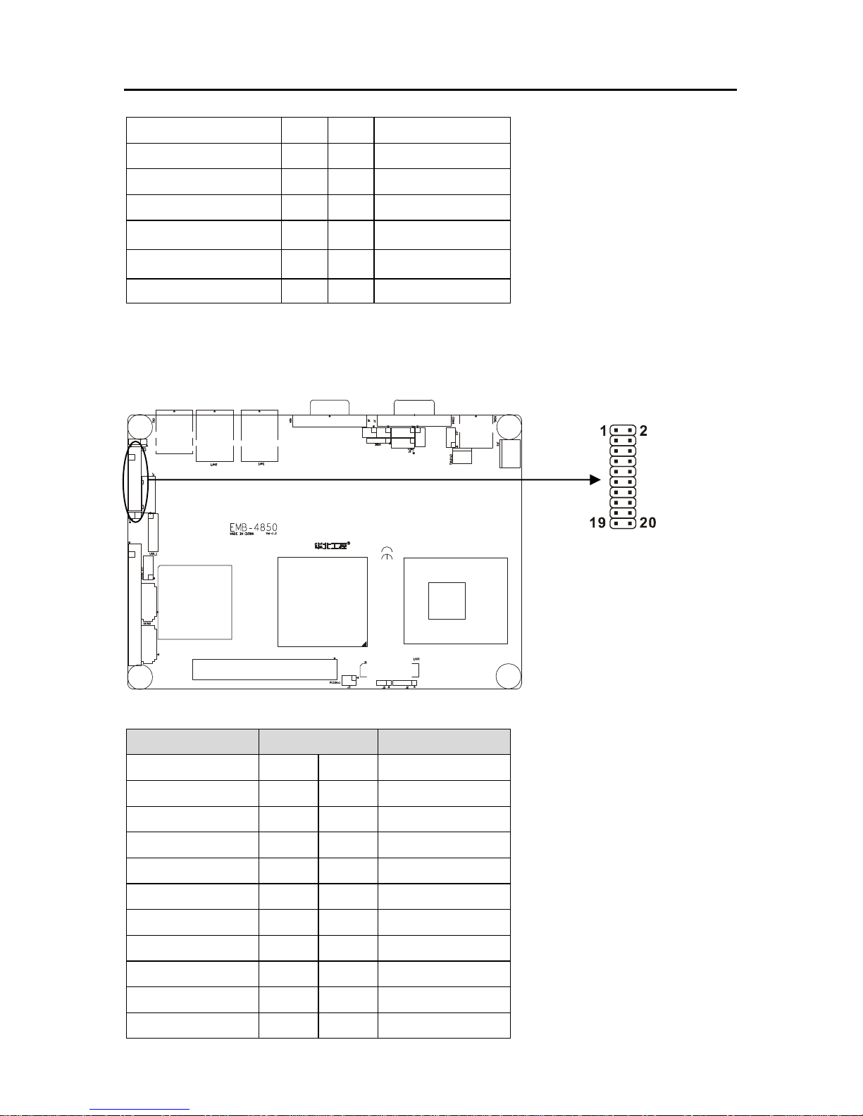
2.6.2 Parallel Port Connector(J13)
Normal 26 Pin Parallel Port,According to your needs to connect parallel port device。
J13:
Signal name Pin Signal name
T_STB# 1 2 T_AFD#
PDQ0 3 4 T_ERR#
PDQ1 5 6 T_INIT#
PDQ2 7 8 T_SLIN#
PDQ3 9 10 GND
PDQ4 11 12 GND
PDQ5 13 14 GND
PDQ6 15 16 GND
PDQ7 17 18 GND
T_ACK# 19 20 GND
T_BUSY 21 22 GND
11
Page 23
EMB-4850 EPIC Embedded board
T_PE 23 24 GND
T_SLCT 25 26 GND
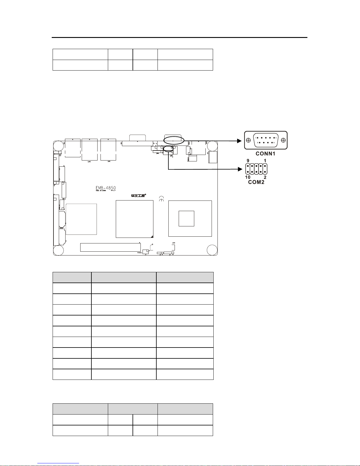
2.6.3 Serial port Connector(CONN1、COM2)
This board provides 2 serial ports (COM1:RS-232;COM2:RS-232/422/485)in 1 DB-9
connector(CONN1) and 1 2×5 header. You can enable/disable them and choose the IRQ or I/O
address from BIOS SETUP.COM2 setting refer to” 2.3.3 COM2 setting(J7、J8、J9)”.
CONN1:
Pin Signal name Signal name
1 DCD Data Carrier Detect
2 RXD Receive Data
3 TXD Transmit Data
4 DTR Data Terminal
5 GND System Ground
6 DSR Data Set Ready
7 RTS Request to Send
8 CTS Clear to Send
9 RI Ring Indicator
COM2:
Signal name Pin Signal name
DCD 1 2 DSR
RXD 3 4 RTS
12
Page 24

EMB-4850 EPIC Embedded board
TXD 5 6 CTS
DTR 7 8 RI
GND 9 10 GND
2.6.4 Display Connector(VGA1、LVDS1、J3、J2)
The board has 3 connectors to support these displays: one for standard CRT VGA
monitors (15DB), one for TV displays (HD TV and SD TV), and one for LVDS type LCD
panels.VGA+LVDS and TVOUT+LVDS dual independent display
VGA:
Pin Signal name Pin Signal name Pin Signal name
1 Red 6 GND 11 NC
2 Green 7 GND 12 SDA
3 Blue 8 GND 13 HSYNC
4 NC 9 +5V 14 VSYNC
5 GND 10 GND 15 5VDDCK
LVDS:
Signal name Pin Signal name
VDDLVDS 1 2 VDDLVDS
GND 3 4 GND
13
Page 25

EMB-4850 EPIC Embedded board
14
LA_DATAN0 5 6 LB_DATAN0
LA_DATAP0 7 8 LB_DATAP0
GND 9 10 GND
LA_DATAN1 11 12 LB_DATAN1
LA_DATAP1 13 14 LB_DATAP1
GND 15 16 GND
LA_DATAN2 17 18 LB_DATAN2
LA_DATAP2 19 20 LB_DATAP2
GND 21 22 GND
LA_CLKN 23 24 LB_CLKN
LA_CLKP 25 26 LB_CLKP
GND 27 28 GND
L_DDC_DATA 29 30 L_DDC_CLK
NC 31 32 NC
GND 33 34 GND
LVDS PANEL BACKLIGHT(J2):
TV-OUT(J3):
Signal name Pin Signal name
DACA_OUT 1 2 GND
DACB_OUT 3 4 GND
DACC_OUT 5 6 GND
Pin Signal name
1 +12V
2 L_BKLTEN
3 L_BKLTCTL
4 GND
5 VCC
Page 26

EMB-4850 EPIC Embedded board
15
2.6.5 USB Connector (USB1、CN1)
Onboard provide a standard dual-layer USB port and a set of 2×5 header USB ports,
which both support USB 2.0 at a high speed of 480Mbps.
Signal name Pin Signal name
VCC 1 2 GND
USB D- 3 4 GND
USB D+ 5 6 USB D+
GND 7 8 USB D-
GND 9 10 +5V
Page 27

EMB-4850 EPIC Embedded board
16
2.6.6 SATA Connector (SATA1、SATA2)
EMB-4850 supports Serial ATA via two connectors (SATA1、SATA2). Data transfer rates
up to 300 MB/s are possible, enabling very fast data and file transfer, and independent DMA
operation on two ports.
SATA1、SATA2:
Pin Signal name
1 GND
2 SATA_TXP
3 SATA_TXN
4 GND
5 SATA_RXN
6 SATA_RXP
7 GND
Page 28

EMB-4850 EPIC Embedded board
17
2.6.7 IrDA(IRDA)
This board provides a group of IrDA pins, support IrDA version 1.0 SIR or SHARP ASK-IR
protocol infrared ray transmission function
IRDA:
Pin Signal name
1 VCC
2 NC
3 IRRX
4 GND
5 IRTX
Page 29

EMB-4850 EPIC Embedded board
18
2.6.8 Audio Connector(J11)
Realtek ALC888 Audio, Support 7.1 channels HD audio output.
J11:
Signal name Pin Signal name
SPKOUT_R 1 2 AUDIO_GND
SPKOUT_L 3 4 AUDIO_GND
LINEOUTR 5 6 LINEOUT_L
AUDIO_GND 7 8 AUDIO_GND
LINE_R 9 10 LINE_L
AUDIO_GND 11 12 AUDIO_GND
NULL 13 14 MIC_IN_L
MIC_IN_R 15 16 AUDIO_GND
Page 30

EMB-4850 EPIC Embedded board
19
2.6.9 CPU FAN Connector (CPUFAN)
This board provide a 3Pin CPU fan socket, attention: electric current for fan≤350mA (4.2W,
12V), affirm fan cable matches fan socket.
CPUFAN:
Pin Signal name
1 GND
2 VCC12
3 Speed detect
2.6.10 Power Connector (JP2)
+12V Single power supply.
Page 31

EMB-4850 EPIC Embedded board
20
2.6.11 Ethernet Connector (LAN1、LAN2)
Onboard provide 2 1000Mbps Ethernet interface, LILED and ACTLED separately is aside
LAN yellow color led and green led. They indicate LAN’s linking state and transmitting active
state
TX+,TX-:positive/negative send data signal; RX+,RX-:positive/negative receive data signal
ACTLED:network active state LED; LILED:network linking state LED.
LED state description:
LILED(Yellow) Network link status ACTLED(green) Message transfer status
On effective On transfering
Off invalidation Off NO message transfering
LAN:
Signal name Pin Signal name
TX+ 1 2 TX-
RX+ 3 4 NC
NC 5 6 RX-
Pin Signal name
1 +12V
2 GND
3 GND
LAN1
LAN2
Page 32

EMB-4850 EPIC Embedded board
21
NC 7 8 NC
2.6.12 PS/2 KB/MS connector(KBM1)
1 PS/2 kb/ms jack, need to be Connected with PS/2 KB/MS Y-shape convert cable.
KBM1:
Signal name Pin
KB_DATA 1
MS_DATA 2
GND 3
+5V 4
KB_CLK 5
MS_ CLK 6
2.6.13 Front Panel Connector (J10)
This connector mainly supply power indicator led , hard disk indicator led , power restart
indicator led, power auto-manage indicator led, restart button and sleep button etc. connecting
pin.
Page 33

EMB-4850 EPIC Embedded board
22
.
Signal description Pin Signal description
POWERSW- 1 2 5VSB
RSTBTN# 3 4 GND
GRELED+ 5 6 GRELED-
HDD LED+ 7 8 HDD LED-
1) Power On/Off Control Pins (J10 pin1&2 for PWRSW)
Connect these two pins with bounce switch on panel of chassis, can switch-on or
switch-off power.
2) Reset Button Pins(J10 pin3&4 for RESET )
Connect this pins and RESET switch on panel of chassis with cable. When system can not
work on, reset can make system restart, without turning on/off the power, thereby it can prolong
system serviceable life.
3)Sleep LED Pins(J10 pin 5&6 for GREEN LED)
Connect these two pins with power LED(Pin5 is anode),when it is power-on, LED light on;
power-off, LED light off; winking means sleeping
4) IDE LED Pins (J10 pin7&8 for HDD LED)
As a rule, there is a IDE LED on the panel of chassis, while IDE device(like hard Disk) is
reading or writing(no matter which IDE device), LED will flash, shows that IDE Device is
Page 34

EMB-4850 EPIC Embedded board
23
running. Connect IDE LED on chassis panel and these pins (pin20 is LED anode).
2.6.14 PC/104+
A standard PC104 + expansion slot, users can choose a different PC/104 + extension
according to their own needs . different modules of the input voltage is not the same, you can
through the PC/104 + module voltage jumper to set.
Pin Signal name Pin Signal name Pin Signal name Pin
Signal
A1 GND/5V B1 NC C1 +5V_4 D1 AD00
A2 VI/O_0 B2 AD02 C2 AD01 D2 +5V_7
A3 AD05 B3 GND_6 C3 AD04 D3 AD03
A4 C/BE#0 B4 AD07 C4 GND_11 D4 AD06
A5 GND_0 B5 AD09 C5 AD08 D5 GND_17
A6 AD11 B6 VI/O_1 C6 AD10 D6 M66EN
A7 AD14 B7 AD13 C7 GND_12 D7 AD12
A8 +3.3V_0 B8 C/BE#1 C8 AD15 D8 +3.3V_7
A9 SERR# B9 GND_7 C9 SB#0 D9 PAR
A10 GND_1 B10 PERR# C10 +3.3V_5 D10 SDONE
A11 STOP# B11 +3.3V_3 C11 LOCK# D11 GND_18
A12 +3.3V_1 B12 TRDY# C12 GND_13 D12 DEVSEL
A13 FRAME# B13 GND_8 C13 IRDY# D13 +3.3V_8
PC104+
Page 35

EMB-4850 EPIC Embedded board
24
A14 GND_2 B14 AD16 C14 +3.3V_6 D14 C/BE#2
A15 AD18 B15 +3.3V_4 C15 AD17 D15 GND_19
A16 AD21 B16 AD20 C16 GND_14 D16 AD19
A17 +3.3V_2 B17 AD23 C17 AD22 D17 +3.3V_9
A18 IDSEL0 B18 GND_9 C18 IDSEL1 D18 IDSEL2
A19 AD24 B19 C/BE#3 C19 VI/O_3 D19 IDSEL3
A20 GND_3 B20 AD26 C20 AD25 D20 GND_20
A21 AD29 B21 +5V_2 C21 AD28 D21 AD27
A22 +5V_0 B22 AD30 C22 GND_15 D22 AD31
A23 REQ#0 B23 GND_10 C23 REQ#1 D23 VI/O_4
A24 GND_4 B24 REQ#2 C24 +5V_5 D24 GNT#0
A25 GNT#1 B25 VI/O_2 C25 GNT#2 D25 GND_21
A26 +5V_1 B26 CLK0 C26 GND_16 D26 CLK1
A27 CLK2 B27 +5V_3 C27 CLK3 D27 GND_22
A28 GND_5 B28 INTD# C28 +5V_6 D28 RST#
A29 +12V B29 INTA# C29 INTB# D29 INTC#
A30 -12V B30 NC C30 NC D30 GND
2.6.15 GPIO (J6)
The board supports 8-bit GPIO through GPIO connector. The 8 digital in and out-puts can
be programmed to read or control devices, with input or out- put defined. The default setting is
4 bits input and 4 bits output.
Page 36

EMB-4850 EPIC Embedded board
25
J6:
2.6.16 System Memory
Two SO_DDR2 dual-channel DDRⅡsocket(show as SO_DDR1&SO_DDR2)on board,
when fixing memory bank, pay attention to following advice:
1. During fixing, make its nick aim at the nick of SO-DIMM socket , and work the memory bank
in its socket sideling, then press it adown to the right position, make the handle beside
SO-DIMM socket lock the memory tightly.
2. Support DDRⅡ533/667MHz memory, max. up to 2GB.
3. Recommend using memory with SPD (the memory with auto-detect function), insure
memory work stability.
Signal name Pin Signal name
GPIN 1 1 2 GND
GPIN 2 3 4 GPOUT 1
GPIN 3 5 6 GPOUT 2
GPIN 4 7 8 GPOUT 3
GND 9 10 GPOUT 4
Page 37

EMB-4850 EPIC Embedded board
26
DIMM1
DIMM2
Page 38

EMB-4850 EPIC Embedded board
Chapter 3
BIOS Setup
Page 39

EMB-4850
EPIC Embedded board
27
Chapter 3 BIOS Setep
AMI BIOS upgrade:
It is true that hardware and software are upgrading all the time. When your IPC can not
support the newest processor (for example), you should upgrade the BIOS to try to keep up
with the latest technology. Upgrading (or flashing) the BIOS is not an easy attempt. To make
sure upgrade succeed, please follow the instruction below:
Set jumper JAV as open
Afudos.exe is the program for BIOS to modify and upgrade,need to be run in DOS mode.
Step1: use boot disk load DOS, run Amiflash.exe and write the newest file: XXXX.ROM into the
Flash IC.
Order format: A:\ Afudos XXXX.ROM
If you need to add other parameters, please add <space>/? after the order format.
Example:Afudos 4850I101.rom /P /B /C /N /X
Remarks:
1. Upgrading BISO may cause your system crash, so please operate carefully.
2. Please use the upgrading program in the CD-ROM provided by us
3. Please do not power off or reboot the system when upgrading, otherwise, the BIOS maybe
be damaged.
4. Please backup your BIOS before upgrading
AMI BIOS information
Awards BIOS ROM has a built-in setup program that allows users to modify the basic
system configuration. This type of information is stored in battery-backed memory (CMOS RAM)
so that it retains the setup information when the power is turned off.
AMI BIOS Setup
Power on your computer, when this information display in your screen: Del->SETUP
please press “DEL”, then it will enter BIOS setup interface.
1. Power on or Reset computer;
2. When "Press <Del> to enter setup" in screen, please press <Del>
3. Use the “←↑→↓”to choose the option which your want to modify, press <Enter> and show
Page 40

EMB-4850
EPIC Embedded board
28
the sub-menu.
4. Use the “←↑→↓”and <Enter> to modify the value, or use Mouse do this operation..
5. At any time, press<Esc> can back to the father-menu.
3.1 Main Menu
AMI BIOS (Read only)
BIOS information: such as Version, BIOS ID and Manufactory Day.
Processor (Read only)
CPU information: such as processor type and frequency.
System Memory (Read only)
Memory size
System Time
Format: Hour/Minute/Second
Page 41

EMB-4850
EPIC Embedded board
29
System Date
Format: Day/Month/Date/Year; <Day> is Read only. <Month><Date><Year> can be set
by user
3.2 Advanced Menu
WARNING: Setting wrong values in below sections may cause system to malfunction.
Page 42

EMB-4850
EPIC Embedded board
30
3.2.1 CPU Configuration
Configure advanced settings
Include CPU detail description: Vendor, Type, Frequency, L1 cache, L2 cache…
Execute Disable Bit
Execute Disable Bit functionality can help prevent certain classes of malicious buffer
overflow attacks when combined with a supporting operating system, Execute Disable Bit
allows the processor to classify areas in memory by where application code can execute and
where it cannot. When a malicious worm attempts to insert code in the buffer, the processor
disables code execution, preventing damage and worm propagation.
Core Multi-Processing
This option can ensure kernel load dual-processor in best way
Enabled: use multi-kernel CPU。
Disabled: use one of CPU.
CPU TM function
Page 43

EMB-4850
EPIC Embedded board
31
For enable/disable CPU in-house temperature controlling functions。
Venderpool Technology
Operating System imaginary technology of Intel。It makes one computer run even number
OS, VT Tech makes processor with and/or virtual tech. By Vanderpool Technology, we can run
two OS on one computer at one time, one processor run one OS, the other processor run
another OS.
Intel(R) Speedstep (tm) tech
When you use AC power or battery,dynamically switch voltage and frequency between AC
and battery according to CPU burthen.<Enabled>for open,<Disabled> for close.
Automatic: CPU service frequency self-regulation according to amount of process
Maximum: CPU always run in highest speed
Minimum: CPU always run in lowest speed
Disable: close it
3.2.2 IDE Configuration
ATA/IDE Configuration
Page 44

EMB-4850
EPIC Embedded board
32
This file is for selecting ATA/IDE Configuration mode.
Configure SATA as
SATA configuration mode selection, you can set it as [RAID], [AHCI] or [IDE]
Configure SATA channels
SATA Channels selection,option have Before Pata,After Pata
Primary/Secondary/ Third IDE Master/Slave
IDE device works mode setup: including Type, LBA/Large Mode, Block mode (Multi-Sector
Transfer), PIO Mode, DMA Mode, S.M.A.R.T, 32Bit Data Transfer.
Norco strongly recommends default setting: Let system auto setup your device; if want
self-config, please confirm your Hard Disk information and whether it supports these work
modes or not.
Hard Disk Write Protect
HDD Write Protect function setup: <Enabled> write protect, HDD read only: <Disabled>
HDD can write or read.
IDE Detect Time Out (Sec)
Set BIOS searching IDE device in appoint time (by seconds)
ATA(PI) 80Pin Cable Detection
Set detecting ATA(PI)80pin cable: 80pin ATA cable is for Ultra ATA/66, Ultra ATA/100 and
Ultra ATA/133 .Standard cable is 40pin, can not support high transfer rate. These two cables
are pin compatible.
Page 45

EMB-4850
EPIC Embedded board
33
3.2.3 SupperIO Configuration
Serial Port1 Address
Setup Serial Port1 interrupts and addresses.
Recommend Default set.
Serial Port2 Address
Setup Serial Port2 interrupts and addresses.
Recommend Default set.
On Board CIR Port
This option for configure on board CIR port ,<Enabled>: Open ,<Disabled>: Close
Keyboard/ Mouse PowerOn
Support Keyboard/ Mouse Power On, <Enabled>: Open ,<Disabled>: Close
Page 46

EMB-4850
EPIC Embedded board
34
3.2.4 Hardware Health Configuration
Hardware Health Configuration
Enter this option to examine hardware health , such as CPU temperature, system
temperature etc
Page 47

EMB-4850
EPIC Embedded board
35
3.2.5 ACPI Configuration
ACPI Aware O/S
If you choose <Yes> and system support ACPI, BIOS will according to ACPI criterion to
distribute resource and system will use the resource to manage system power.
(1) General ACPI Configuration
(2) Advanced ACPI Configuration
(3) Chipset ACPI Configuration
ACPI options above are recommended to be kept as optimization setting by system
Page 48

EMB-4850
EPIC Embedded board
36
3.2.6 APM configuration
Power Management/APM
<Enable>: open power saving mode.
<Disable>: close power saving mode
Video Power Down Mode
Video power down mode setting,options <Suspend><Stand by><Disable> for select.
Hard Disk Power Down Mode
Hard disk power down mode setting,options <Suspend><Stand by><Disable> for select.
Suspend Time Out
Set the time limit when system detecting no operation to enter “suspend” mode. The time
limit can be set from 1~60 minutes.
Throttle Slow Clock Ratio
If started up CPU power-save mode,when CPU temperature reaches a fixed value,this
Page 49

EMB-4850
EPIC Embedded board
37
option will show the CPU slow clock ratio.
Keyboard & PS/2 Mouse
If you want set keyboard and PS/2 mouse activities as power-management event, if so, set
Power Management/APM as Enabled, not for Disabled.
Power Button Mode
<Instant Off>: Press “Power” key, system will power on/off.
<Suspend>: Press “Self off after 4sec override” key and system will reboot 4Sec later.
Resume On Ring, LAN, PME#
Set if Ring, LAN, PME can resume your PC, < Enabled> for yes, <Disabled> for no.
Resume On RTC
If timing boot, <Disabled> for no, <Enabled>: Pop-up a window shown two options as
below:
1. <RTC Alarm Date(days)>:for setting the date to boot, selection bound from the 1st
to 31st, also can be set as Every Day, it means timing resume everyday at this time.
2. <System Time>:for setting the time to boot, format is: Hour/Min/Sec
Page 50

EMB-4850
EPIC Embedded board
38
3.2.7 Intel AMT Configuration
Intel AMT Support
Intel AMT, EMB-4850 not support this function pro tempore
Page 51

EMB-4850
EPIC Embedded board
39
3.2.8 MPS Configuration
MPS Revision
It contains MPS Revision options. MPS is Multi Processor Specification for short, this
option make sense just when the system with Multi Processor or Virtual Processor. MPS have
two versions of 1.1 and 1.4. For the OS those advanced than Win2000 are completely
compatible to MPS 1.4, and for the OS version former than WinNT, must select version 1.1.
Wrong set will cause the second processor to be closed.
Page 52

EMB-4850
EPIC Embedded board
40
3.2.9 PCI Express Configuration
Active State Power-Management
Active State Power-Management technology,[Enabled]:open,[Disabled]:Close
Page 53

EMB-4850
EPIC Embedded board
41
3.2.10 Smbios Configuration
Smbios Smi Support
If support SMBIOS PnP Function 50-54h by SMI. [Enabled:Support ],[Disabled:NO
Support].
Page 54

EMB-4850
EPIC Embedded board
42
3.2.11 Remote Access Configuration
Remote Access
If support remote access, yes as [Enabled], no as [Disabled]
Serial Port number
This option for user choose Serial Port number
Serial Port Mode
This item for user choose Serial Port Mode
Flow Control
Flow control.
Redirection After BIOS POST
After BIOS POST do redirection, [Enabled], [Disabled] for select.
Terminal Type
Page 55

EMB-4850
EPIC Embedded board
43
Terminal type selection
VT-UTF8 Combo Key Support
Both support VT and UTF8 ? yes as [Disabled], no as [Enabled]
Sredir Memory Display Delay
Serial port terminal display delay.
3.2.12 USB Configuration
USB Devices Enabled(read only)
This item display system annectent USB device
Legacy USB Support
If need support USB device in DOS mode: such as U Disk, USB keyboard ,then
<Enabled> or<Auto> If not <Disabled>
Port 64/60 Emulation
This option is for control USB port 64/60 emluator function. When it startup this function,
Page 56

EMB-4850
EPIC Embedded board
44
USB keyboard can gather some special key combination.Close:<Disabled>,Open:< Enabled>
USB 2.0 Controller Mode
This option for choose USB2.0 port mode, <FullSpeed>: USB port 2.0 (480Mbps).
<HiSpeed>: USB port 1.1 (12Mbps).
BIOS EHCI Hand-Off
<Enabled>:When enter OS, BIOS auto close. <Disabled>:When enter OS, BIOS closed
by OS.
USB Mass Storage Device Configuration
USB Mass Storage Reset Delay
This option allows you to choose your system bios usb storage devices to detect the
waiting time
Emulation Type
Setup removeable Disk mode when use U Disk boot up system.
Page 57

EMB-4850
EPIC Embedded board
45
Mode: Auto/Floppy/Forced FDD/Hard Disk/CDROM. Default set is <AUTO>.
3.3 PCIPNP
WARMING:Setting wrong values in below sections may cause system to malfunction.
Clear NVRAM
YES: after system reboot reset ESCD NVRAM and reset it as NO.
Plug & Play O/S
If OS support hot swap devices, select yes, in this case, system will amend interrupt, I/O
and DMA. If not select No, so BIOS will distribute resources to all devices.
PCI Latency Timer
All PCI latency timer setting. Unit is PCI clock period.
Allocate IRQ to PCI VGA
<Yes>: Allocate IRQ to PCI VGA card
Page 58

EMB-4850
EPIC Embedded board
46
<No>: can not use PCI VGA card
Palette Snooping
Yes: it will inform PCI devices it installed an device based on ISA at this moment, if you
want change the default setting, please consult adapter’s manual first, or set it as No.
PCI IDE BusMaster
<Enabled>: Open BusMaster function: improve PCI IDE device transfer speed.
<Disabled>: close BusMaster function.
OffBoard PCI/ISA IDE Card
<Auto>: System detect device automatically.
3.4 Boot Menu
Display VGA Priority
Display VGA priority set.
Page 59

EMB-4850
EPIC Embedded board
47
Onchip VGA Share Memory
Shared graphic memory size setting, this option only take effect before VGA driver loading,
after driver loading, it will redistribute graphic memory according to system memory, size up to
224M.
3.4.1 Boot Settings Configuration
Quick Boot
<Enabled>: Load OS without BIOS self-detecting,
<Disabled>: Load OS after BIOS detected.
Full Screen Logo
<Enabled>:Show user-defined welcome interface before you loading OS,
<Disabled>:Show default welcome interface before you loading OS
AddOn ROM Display Mode
For choosing Option ROM display mode,Setting value:[Force BIOS][Keep Current].
Bootup Num-lock
Page 60

EMB-4850
EPIC Embedded board
48
Num-lock state while boot (on/off)
PS/2 Mouse Support
PS/2 mouse support setting
<Enabled>: support
<Disabled>: not support
<Auto>: automatically
Wait For “F1” If Error
<Enabled>: waiting user press ”F1” if OS detect incorrectly.
<Disabled>: neglect errors, directly loading OS
Hit ‘DEL’Message Display
<Enabled>: When display BIOS logo, also has ‘DEL’ notice
<Disabled>: No ‘DEL’ notice.
Interrupt 19 Capture
If BIOS start-up can be captured by special outside insert card.
<Enabled>: Yes, here BIOS will start-up by inserted card setting in its ROM,
<Disabled>: No, here BIOS start-up by the influence of inserted card.
Page 61

EMB-4850
EPIC Embedded board
49
3.4.2 Boot Device Priority
Boot Device Priority
Press “Enter” will has sub-menu:
1st Boot Device
2nd Boot Device
System will detect device after this priority until find an available boot device,Boot device
support Removable Drive or Hard Disk Drive
Page 62

EMB-4850
EPIC Embedded board
50
3.4.3 Hard Disk Driver
Hard Disk Drives
If has multi- HDD, must set up priority. The Highest Priority HDD will display in “Boot
Device Priority”
Page 63

EMB-4850
EPIC Embedded board
51
3.5 Security Menu
Supervisor Password(read-only)
If set up supervisor password, will display “Installed”,If not , will display “Not Installed”
User Password(read-only)
If set up user password, will display “Installed”,If not , will display “Not Installed”
Change Supervisor Password
Select the Supervisor or User icon from the Security section of the BIOS Setup main menu.
Enter the password and press <Enter>. The screen does not display the characters entered.
After the new password is entered, retype the new password as prompted and press <Enter>.
Change User Password
Press ‘Enter ‘, and enter sub-menu then you can change supervisor password.。
Clear User Password
Press ‘Enter ‘, and select “yes” then you can clear user password.
Page 64

EMB-4850
EPIC Embedded board
52
Boot Sector Virus Protection
<Enabled> : Boot sector virus protection will be enabled. When execute Disk format or
Write the Bootable section instruction, BIOS will send a warning.
Example as below:
Boot Sector Write!
Possible VIRUS: Continue (Y/N)? _
(Must press much ‘N’ and skip up )
Format!!!
Possible VIRUS: Continue (Y/N)? _
(Must press much ‘N’ and skip up )
<Disabled>: close this function.
3.6 Chipset Menu
Page 65

EMB-4850
EPIC Embedded board
53
3.6.1 North Bridge Configuration
DRAM Frequency
Please config memory frequency according to its parameter, advice setting [Auto]。
Configure DRAM Timing by SPD
<Enabled> system auto-setting memory parameter by SPD .
<Disabled>: Manual setting memory parameter by entering submenu.
PEG Port
PCI Express Graphics port ,open or close, default set is <Auto>
PEG Force×1
PCI Express Graphics port transmission speed setting
<Enabled>:×1 mode,
<Disabled>:default
Chipset Thermal Throttling
Page 66

EMB-4850
EPIC Embedded board
54
Function of CPU thermal throttling, enter in it, you can set its temperature and enable it or
not
DT in SPD
Delta temperature (DT) in SPD.
TS on DIMM
TS on DIMM Tech, utilize a physic heat sensor integrated in DIMM to monitor DIMM
temperature.
3.6.2 South Bridge Configuration
USB Functions
Option setting Whether to open USB functions,[ Enable: open],[Disable: close]
USB 2.0 Controller
Set USB2.0 port open/close
Audio Controller
Page 67

EMB-4850
EPIC Embedded board
55
Set on-board audio open/close
SLP_S4# Min. Assertion Width
SLP_S4# of memory Min. assertion width setting, Default as:1 to 2 seconds
Restore on AC Power Loss
<Power Off>: boot system after press power button while power supply connected
<Power On>: boot system straightway while power supply connected
<Last State>: according to the setting by last time.
PCIE Ports Configuration
PCIE Port0-5
South Bridge integrate 6 PCIE-X priority
PCIE High Priority Port
Set PCIE port priority
3.6.3 Video Function Configuration
Page 68

EMB-4850
EPIC Embedded board
56
DVMT Mode Select
Setup the first used internal display device, can be set as:[Fixed Mode] [DVMT Mode].
[DVMT]: dynamic shared graphic memory size, driver will dynamic distribute system
memory size to it
[FIXED]: fixed shared memory, driver will distribute system memory size according to
BIOS setting
DVMT/FIXED Memory
Show DVMT/Fixed memory size.
Boot Display Device
Display devices setting, such as LVDS+CRT, CRT, LVDS, TV etc.
Flat Panel Type
This option is for set LCD type and resolution
Local Flat Panel Scaling
LVDS full screen display or all content display setting
TV Connector
TV-OUT port selection
HDTV Output
High-Definition TV output format set.
TV Standard
TV output type selection
TV Sub-Type
TV output sub-type selection
Page 69

EMB-4850
EPIC Embedded board
57
3.7 Exit Menu
Save Changes and Exit
Press <Enter> and <Enter>, to save BIOS change and reboot system.。
Discard Changes and Exit
Press <Enter> and <Enter>, will does not save BIOS change and reboot system.
Discard Changes
Press <Enter> and <Enter>, and continue set BIOS.
Load Optimal Defaults
Recommend user first to use this option before config BIOS.
Load Failsafe Defaults
If System fails, recommend to load this option.
Page 70

Appendix
Page 71

EMB-4850
EPIC Embedded board
58
Appendix
Appendix 1: Driver Installation
Please install drivers according to following steps:
1: click right on "My Computer" icon on the desktop, and then select "Properties" in the pop-up
menu, and enter "System Properties" menu.
2: Select the "hardware" tab, then enter the "Device Manager", double-click on the yellow
question mark or an exclamation point with the hardware "in upgrading Driver" and enter
"hardware Update Wizard."
3: Choose "from the list or specified location to install (Senior)" to enter the next step, select
"search in these locations on the best driver," then "Search removable media……" and "in the
search included in this position " ”√” bear.
4: Click on "Browse", please place the location of browse to the disc corresponding folder, find
the correct driver installation file and then click OK to enter the next step.
5: Complete the installation of hardware according to prompts, then restart your computer to
drive the entry into force.
6: Repeat steps 1-5 to complete all procedures for the installation of hardware drivers.
Page 72

EMB-4850
EPIC Embedded board
59
Appendix 2:Watchdog programmer guide
watchdog Timer Setting(ASM):
--------------------------------------------------------------------------------------------------------------
Set Watchdog Timer as 48 sec.(max. support 0xFF=255, set as 00 to stop watchdog), run
debug in DOS mode:2EH: address port, 2FH: data port
C:\>debug
-o 2e 87
-o 2e 87 ;decode
-o 2e 2b
-o 2f e0 ;bit4=0 ,set pin as watchdog func
-o 2e 07
-o 2f 08 ; select logic device
-o 2e 30
-o 2f 01 ;logic device activation
-o 2e f5
-o 2f 00 ;set count unit as second/(minute as o 2f 08)
-o 2e f6
-o 2f 30h ;set Timer unit as 30h=48 sec.
-o 2fe aa ;lock register
-q
C:\>
-----------------------------------------------------------------
System will reboot after 48sec. time counting till user input last line of codes
===========================================================
Watchdog Timer Setting (c++ language):
----------------------------------------------------------------------------------------------------
outputb (0x2e, 0x87)
outputb (0x2e, 0x87) // open SUPER IO register
outputb (0x2e, 0x2B)
outputb (0x2f, 0xE0) //bit4=0 ,set pin as watchdog func
outputb (0x2E, 0x07)
outputb (0x2F, 0x08) //select logical device
Page 73

EMB-4850
EPIC Embedded board
60
outputb (0x2e, 0x30)
outputb (0x2f, 0x01) //active the device
outputb (0x2e, 0xF5)
outputb (0x2f, 0x00) //set timer unit as second /(minute: outputb (0x2f, 0x08))
outputb (0x2e, 0xF6)
outputb (0x2f, 0x30) //set Timer Count as 30h=48second
outputb (0x2E, 0xAA) //lock SUPER IO register
//------- code end ---------------------------------
Page 74

EMB-4850
EPIC Embedded board
61
Appendix 3: Glossary
ACPI:
Advanced Configuration and Power Management Interface for short,ACPI specification
allows OS to control most power of computer and its extended devices. Windows 98/98SE,
Windows 2000 and Windows ME are all support ACPI, it provide users a flexible system power
management.
ATX:
AT extended, a motherboard layout according with modern standard replaced Baby AT. It
changes disposal of many components, and do some new high efficiency design, so it is widely
used now.
BIOS:
Basic in/out system. It’s a kind of software including all in/out control code interface in PC.
It will do hardware testing while system booting, then system runs, it provides an interface
between OS and hardware. BIOS is stored in a ROM chip.
BUS:
In a computer system, it’s the channels among different parts for exchanging data; it’s also
a group of hardware line. BUS here means part lines inside CPU and main components of
memory.
Chipset:
Integrated chips for executing one or more function. Here “Chipset” means system level
chipset structured by Southbridge & Northbridge; it decides motherboard’s structure and main
functions.
CMOS:
Complementary Metal-Oxide Semiconductor, a widely used semiconductor with the
characteristic of high speed but low power. CMOS we mention here means part of obligate
space in on-board CMOS RAM, for saving date, time, system information and system
parameter etc.
Page 75

EMB-4850
EPIC Embedded board
62
COM:
Computer-Output Microfilmer. A universal serial communication interface, usually adopts
normative OB 9 connector.
DIMM:
Dual Inline Memory Module. It’s a small circuit board with memory chipset, providing 64bit
bus width.
DRAM:
Dynamic Random Access Memorizer. It’s a normal type of memory often with a transistor
and a capacitance to store 1 bit. With the development of the technology, more and more types
and specification of ORAM exist in computer application. Now: SDRAM, DDR SDRAM and
RDRAM are generally used.
IDE:
Driver specification for integrated device electronics,for connecting HDD/CD-ROM device.
IRDA:
Infrared Data Association for short here means infrared transmit interface, to connect
infrared transmit devices. This sort of device transmits data by infrared light-wave without
connecting any cables .It have been developed a standard now.
LAN:
Network interface. Network grouped by correlative computers in a small area, generally in
a company or a building. Local area network is buildup by sever, workstation, some
communications links, as a rule. Terminals can access data and devices anywhere through
cables, so, many users can share costly device and resource.
LED:
Light-emitting diode, it’s a semiconductor device. It will shine when power supply is
connected, often use to denote info lightly, for example, to denote power on or HDD work
normally.
LPT:
Line print terminal. The denomination reserved by DOS, is used to denote universal
Page 76

EMB-4850
EPIC Embedded board
63
parallel interface, and connect printer in a general way.
POST:
Self-test when power on. While booting, BIOS will do once uninterrupted testing operation
to the system, including RAM, keyboard, hard disk driver etc. Check them in normal situation
and work well.
PS/2:
A keyboard & mouse connective interface specification developed by IBM.PS/2 is a DIN
interface with only 6PIN; it also can connect other devices, like modem.
USB:
It’s Universal Serial Bus for short. A hardware interface adapts to low speed external
devices, and is always used to connect keyboard, mouse etc. One PC can connect 127 USB
devices Max, providing 12Mbit/s transmit bandwidth;USB supports hot swap and multi- data
stream, namely, you can plug USB devices while system is running, system can auto-detect
and makes it work on
Page 77

 Loading...