

Page 1
EMB-3682
3.5” Embedded Board
USER' Manual
Page 2

Shenzhen NORCO Intelligent Technology CO., LTD.:0755-27331166
Beijing:010-82671166
Shanghai:021-61212088
Chengdu:028-85259319
Shenyang:024-23960846
Xi’an:029-88338386
Nanjing:025-58015489
Wuhan:027-87858983
Tianjin:022-23727100
Singapore:65-68530809
For more information, please visit our website:http:// www.norco-group.com
EMB-3682
3.5” Embedded Board
USER' Manual
Page 3

Place/Data: HONG KONG/2008
EMB
-
3682
Embedded Board
Shenzhen NORCO Intelligent Technology CO.,LTD.
Shenzhen NORCO Intelligent Technology CO.,LTD.
Page 4
Data: 2007
Trade Name:Shenzhen NORCO Intelligent Technology CO.,LTD.
Model Name:EMB-3682
Responsible Party:Shenzhen NORCO Intelligent Technology CO., LTD.
Equipment Classification:FCC Class B Subassembly
Type of Product: Embedded Board
Manufacturer:Shenzhen NORCO Intelligent Technology CO.,LTD.
Page 5

Content
Chapter 1 Product Introduction.........................................................................1
1.1 Overview...............................................................................................1
1.2 Key Features.........................................................................................1
Chapter 2 Quick Installation Guide....................................................................4
2.1 Layout...................................................................................................4
2.2 Jumper Setting.......................................................................................4
2.2.1 CMOS Content Clearance/Hold Setting(JCC) ..................................4
2.2.2 CF Card Function Master/Slave Selection(JCF)...............................5
2.2.3 COM2 Jumper Setting (J16, J17, J18)..................................................6
2.2.4 Anti-virus BIOS-protect Jumper Setting(JAV) ...................................7
2.2.5 PC 104+ Voltage Setting (J3V, J5, J5V, J12V)......................................8
2.2.6 Panel VCC Selection Jumper Setting (J2, J3)......................................10
2.3 External Interfaces................................................................................10
2.3.1 Mini IDE.............................................................................................11
2.3.2 CF Card Socket (Compact Flash).......................................................12
2.3.3 Serial Ports........................................................................................12
2.3.4 Parallel Port.......................................................................................14
2.3.5 Display Interface (VGA, LVDS, TFT)...................................................15
2.3.6 LCD Backlight Control........................................................................17
2.3.7 Ethernet Port (LAN1/2).......................................................................18
2.3.8 GPIO (JGP).......................................................................................19
2.3.9 Audio Interface (J9)............................................................................19
2.3.10 USB Ports (USB_12, USB_34).........................................................20
2.3.11 KB/MS Connector (KBM)..................................................................22
2.3.12 IrDA Interface (IrDA).........................................................................22
2.3.13 Power Interface (VIN).......................................................................23
2.3.14 Front Panel Connector (J1)...............................................................24
2.3.15 Memory Socket (DDR)......................................................................25
2.3.16 PC 104 Plus Socket (PC 104+).........................................................25
Chapter 3 AMI BIOS..........................................................................................27
3.1BIOS Upgrading.....................................................................................27
Page 6

3.2 AMI BIOS Description............................................................................27
3.3 BIOS Parameter Configuration..............................................................27
3.4 Main Menu............................................................................................28
3.5 Advanced Menu....................................................................................29
3.5.1 CPU Configuration.............................................................................30
3.5.2 IDE Configuration...............................................................................31
3.5.3 Super I/O Configuration......................................................................32
3.5.4USB Configuration..............................................................................34
3.5.5 USB Mass Storage Device Configuration............................................35
3.5.6 PCI PnP.............................................................................................36
3.6 Boot Menu............................................................................................38
3.7 Security Menu.......................................................................................40
3.8 Chipset Menu........................................................................................42
3.9 Power Menu.........................................................................................44
3.10 Exit Menu............................................................................................45
Chapter 4. Drivers Installation..........................................................................46
4.1 Installation Steps................................................................................47
Appendix...........................................................................................................48
Appendix 1: Glossary..................................................................................48
Appendix 2: Watchdog programming guide..................................................51
Page 7

Chapter 1
Product Introduction
Page 8

EMB-3682 AMD LX700, support VGA+LVDS or TTL
1
Chapter 1 Product Introduction
1.1 Overview
NORCO-3682 is a lower consume 3.5〞embedded motherboard, It utilizes AMD
LX700 CPU and CS5536 chipset, 433MHz CPU frequency. Power-consume is only
1.8W, fanless design, single power supply (+5V to +24V) with 6W
power-consumption only on the whole board. It also utilizes one 200-pin DDR
SO-DIMM supporting 333/400MHz DDR memory up to 1GB. Onboard Integrated
two Realtek RTL 8100C chipset network adapters;one Mini IDE slot;Four USB 2.0,
four serial ports, one parallel port, providing users a high-performance, high-security
and high-stability network platform.
Rich I/O ports provided: two IDE connectors, one CF socket for all mainstream
Compact Flash Cards.
In addition, other advanced functions is provided, such as ACPI, make host with
lowest power consumed, CRT, TFT& LVDS display output supported, one IrDA one
PC104 plus. Watchdog Timer supported.
1.2 Key Features
1.2.1 Dimension
●145mm×102mm
1.2.2 MircroProcessor
●AMD LX700 433MHz, 1.3W power consumption and fanless
1.2.3 Chipset:
——AMD LX700 integrated
●Support DDR SO-DIMM
●Support CRT, LCD display mode
——AMD CS5536
●Provide four USB2.0(480MB/S)port
●Support one MINI IDE
Page 9

EMB-3682 AMD LX700, support VGA+LVDS or TTL
2
1.2.4 System Memory
●One DIMM slot
●Support DDR 333/400
●Up to 1GB
1.2.5 Display Interface
●LX700 integrate VGA and LCD controller
●DB15 CRT, graphic memory can be adjusted in BIOS
●18/24bit TFT LCD(TTL)
●LVDS(optional):single channel 18bitLVDS, adjustable-brightness
●Not support TFT LCD & LVDS synchronously display
1.2.6 Audio
●AC’97 DODEC
● Provide Speak out, MIC-IN
1.2.7 On-board LAN
●Realtek RL 8100C
●Support two 10/100Mbps LAN ports
●Two RJ45
1.2.8 ON-board IDE
●One 2×22 Header DIP, 2.00mm IDE connector
●Compact Flash: 50PIN Socket, supports DMA
1.2.9 Supper I/O
●Using Winbond W83627HF chipset
●GPIO supported
●Two 2x5Header interface, 4*USB2.0
●KB/MS connector supports p/s2 MINI-DIN interface
●One IRDA connector
●One parallel connector, PRINT: 2x10 Header
Page 10

EMB-3682 AMD LX700, support VGA+LVDS or TTL
3
1.2.10 BIOS
●4M bit Flash BIOS
1.2.11 Serial Communication Port
●COM1: Standard DB9 interface
●COM2/3/4 adopt 2x5Header 2.54 mm interface
●COM1/3/4->RS232, COM2->RS232/422/485
●COM3/4 adopt W83627HF expansions
1.2.12 Watchdog Timer
●Support hardware reset function
1.2.13 Power Supply
●Single power supply +5V~+20V
● Floppy Driver Connector
1.2.14 Advanced Features
●Provide 1*Compact Flash socket
●Provide one PC104 PLUS
●8-layer PCB
1.2.15 Environment
● Operating Temp:0-60℃
●Operating Humidity:5%-95% no condensation
Page 11

Chapter 2
Quick Installation Guide
Page 12

EMB-3682 AMD LX700, support VGA+LVDS or TTL
- 4
-
Chapter 2 Quick Installation Guide
2.1 Layout
The following picture is interface index for EMB-3682, when you install your devices,
please consult it and read the following guide. During installation please care for
some devices. Incorrect installation will lead to malfunctions.
Remark:During installation, please put on antistatic gloves in case of any damage
EMB-3682 Interface Location
2.2 Jumper Setting
*REMIND:
Jumpers are located on the mainboard, they represent clear CMOS jumper JCC etc.
pin1 for all jumpers are located on the side with a thick white line(pin1 .) refer to
the mainboard′s silkscreen , jumpers with three pins will be shown as to
represent pin1&pin2 connected and to represent pin2&pin3 connected.
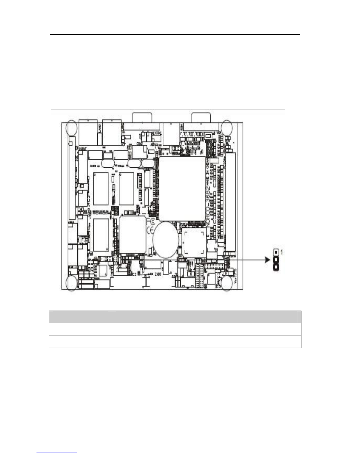
2.2.1CMOS Content Clearance / Hold Setting(JCC)
Board contains a CMOS RAM, where the instored CMOS data is maintained by an
Page 13
EMB-3682 AMD LX700, support VGA+LVDS or TTL
- 5
-
external battery. If you want to reset the CMOS data, first disconnect the power
supply (10V/220V) and set J1 to 1-2 closed for just a few seconds, then move the
jumper JCC back to the default status with pin2-3 closed and power on the system
again.
Setting state
1-2 Clear CMOS (retrieve the initial set)
2-3 Normal(default)
*Do not clear CMOS when power on, otherwise the motherboard will be damaged
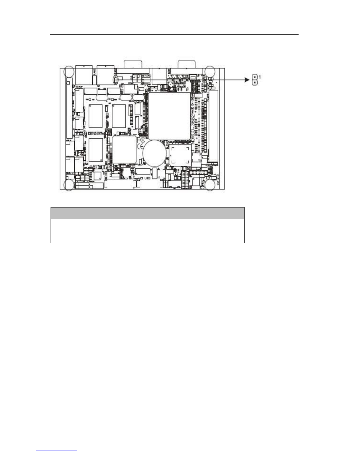
2.2.2 CF Card Function Master/Slave Selection(JCF)
The jumper is used for setting CF card’s slave or master disk. When JCF is closed,
CF card is Master device. When you remove jumper, it will be slave.
Page 14
EMB-3682 AMD LX700, support VGA+LVDS or TTL
- 6
-
Setting JCF
Close Set CF card as master(Default)
Open Set CF card as slave
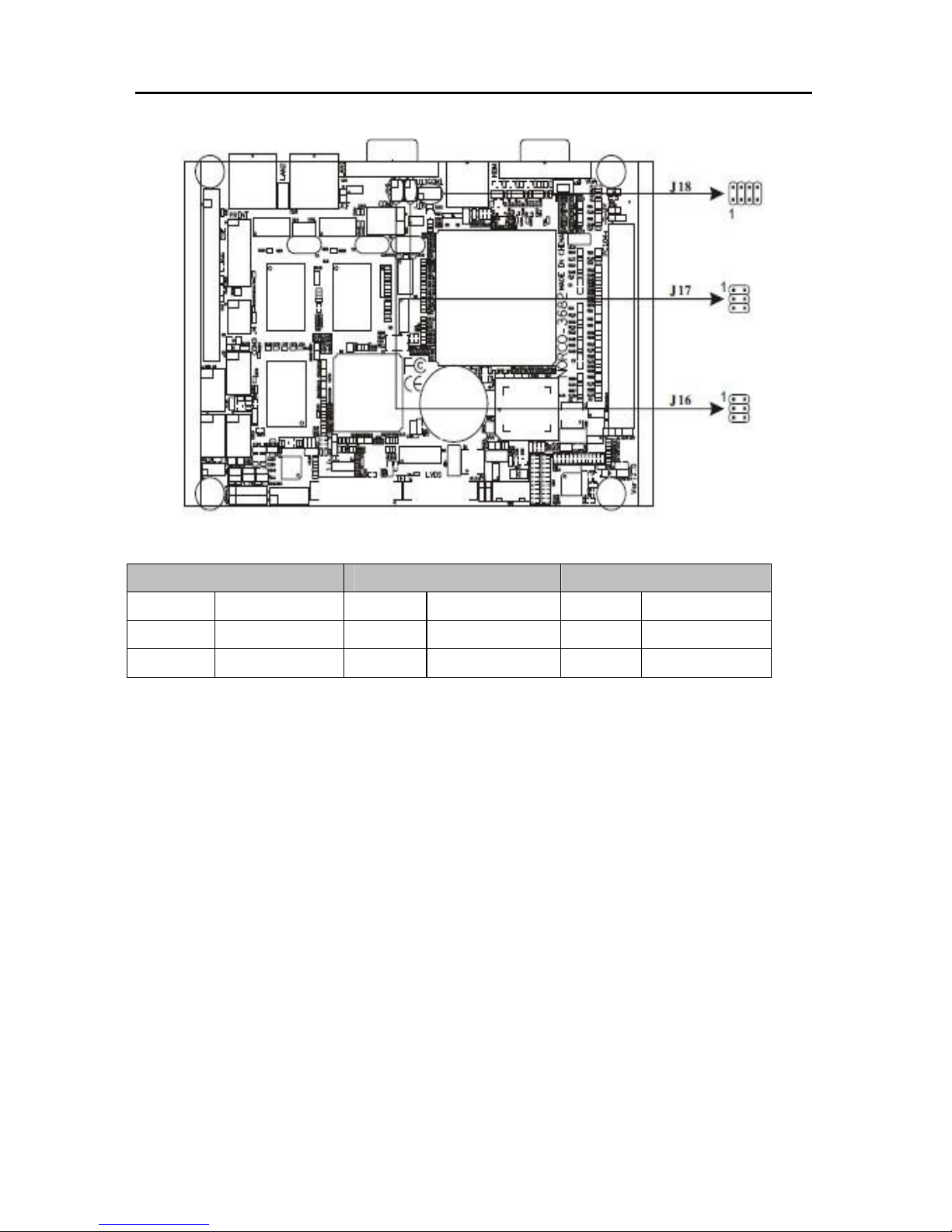
2.2.3 COM2 Jumper Setting(J16, J17, J18)
J16, J17, J18 are used to config COM2 transmission mode. COM2 supports
RS232/422/485 three transmission modes. Users can choose different configuration
according to the actual requirements. Defaut as RS232.
Page 15
EMB-3682 AMD LX700, support VGA+LVDS or TTL
- 7
-
COM2 RS232(Defaut)
COM2 RS422 COM2 RS485
J16 3-4 4-6 J16 1-3 2-4 J16 1-3 2-4
J17 3-5 4-6 J17 1-3 2-4 J17 1-3 2-4
J18 1-2 J18 3-4 J18 5-6 7-8
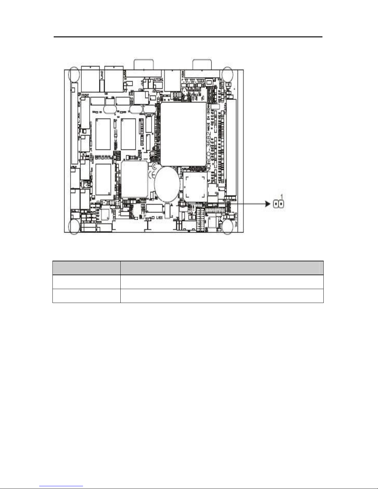
2.2.4 Anti-virus BIOS-protect Jumper Setting (JAV)
The BIOS of the board is contained in the Flash ROM. If the jumper JAV is set as
closed, you will be unable to flash the BIOS and the system BIOS is also protected
from being attacked by serious virus such as CIH virus. If you want to flash the BIOS,
please open this Jumper.
Page 16
EMB-3682 AMD LX700, support VGA+LVDS or TTL
- 8
-
JAV WRITE FLASH
close Disabled(default)
open Enabled
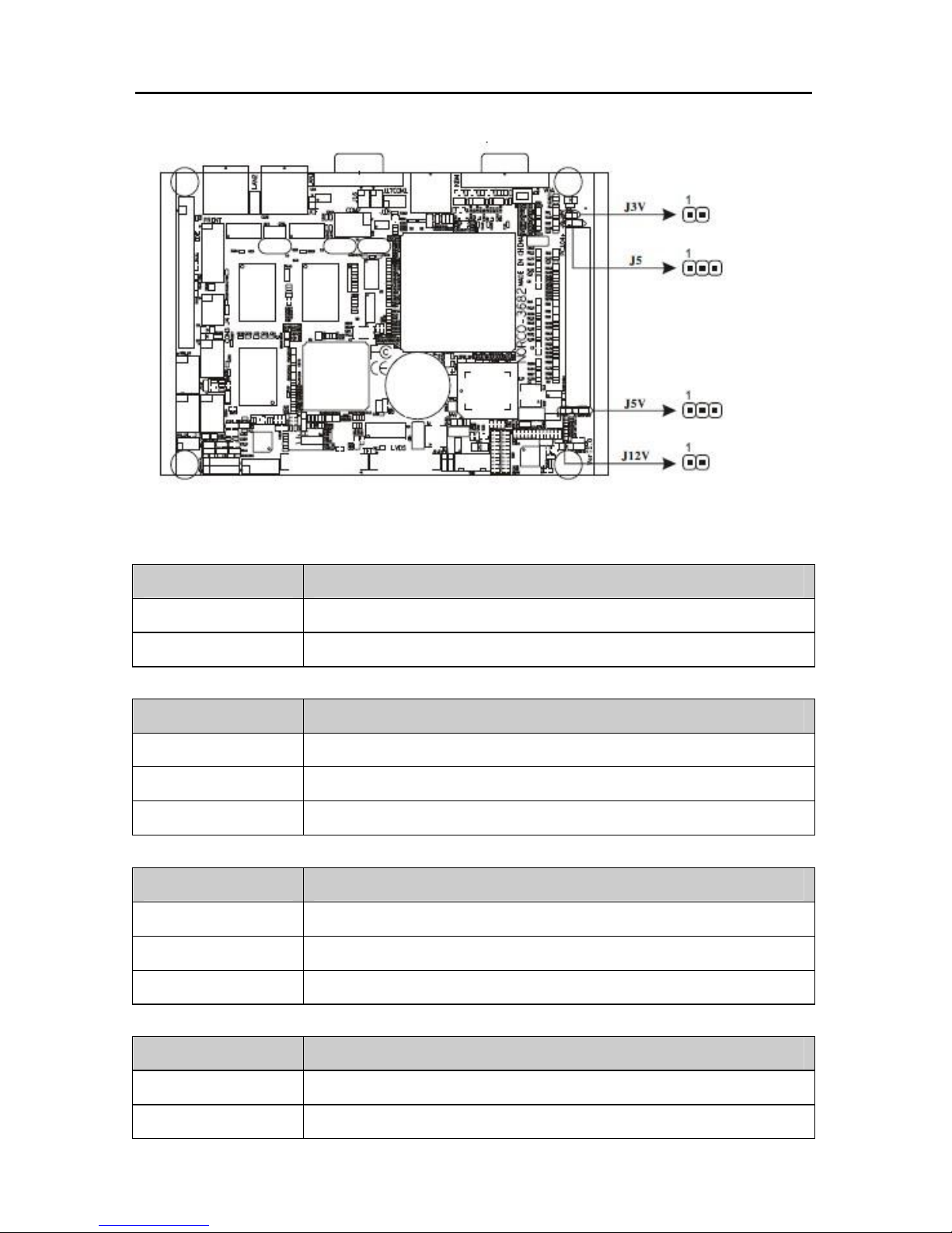
2.2.5 PC 104+ Voltage Setting(J3V, J5, J5V, J12V)
Page 17
EMB-3682 AMD LX700, support VGA+LVDS or TTL
- 9
-
J3V offers voltage supply selection for Pin VCC3 of PC104+.
J3V SETUP
Close Board offers 3V
Open Other way to offer 3V
J5 offers voltage for Pin VIO1-VIO5 of PC104+.
J5 SETUP
Open No offer(default)
1-2 3.3V
2-3 5V
J5V offers voltage supply selection for Pin VCC5 of PC104+.
J5V SETUP
Open No offer(default)
1-2 Board offers 5V
2-3 Other way to offer 5V
J12V
J12V SETUP
Close Board offers 12V
Open Other way to offer 12V
Page 18
EMB-3682 AMD LX700, support VGA+LVDS or TTL
- 10 -
Note:
When using J5V(2-3), J12V can not be closed (1-2); When J12V is closed (1-2), J5V
can not be closed(2-3). When J12V is closed (1-2), PC104+ can also provide power
for EMB-3682.
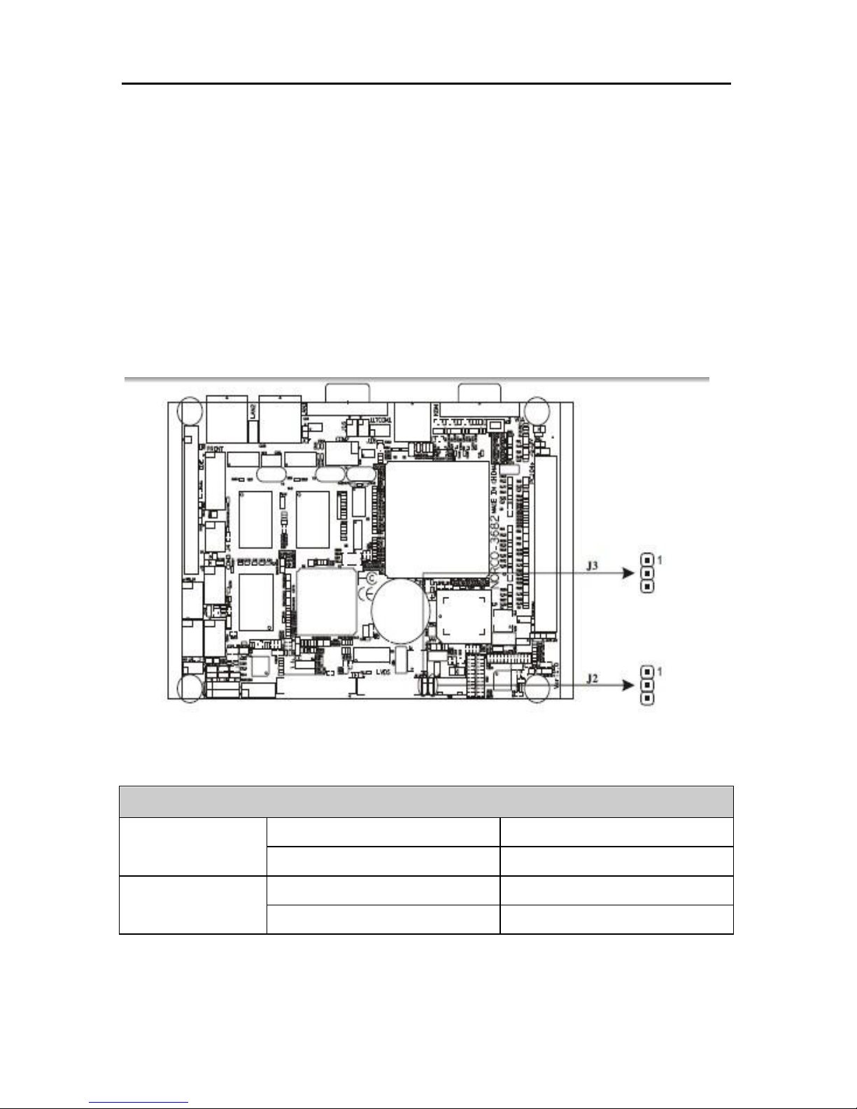
2.2.6 Panel VCC Selection Jumper Setting (J2, J3)
Before switching on LCD display, get information from LCD vendor for rated voltage,
and select its voltage by J2&J3 setting.
PANEL VCC SELECTION
1-2 5V
J3
2-3 3V
1-2 5V
J2
2-3 12V
2.3 External Interfaces
Page 19

EMB-3682 AMD LX700, support VGA+LVDS or TTL
- 11 -
2.3.1 Mini IDE (IDE)
This mini IDE connector is for 2 IDE devices. If you have two IDE hard disks in
system, the second disk must be set as slave disk by jumper setting.
DEFINE PIN#
DEFINE
Reset IDE 1 2 Ground
Host data 7 3 4 Host data 8
Host data 6 5 6 Host data 9
Host data 5 7 8 Host data 10
Host data 4 9 10 Host data 11
Host data 3 11 12 Host data 12
Host data 2 13 14 Host data 13
Host data 1 15 16 Host data 14
Host data 0 17 18 Host data 15
Ground 19 20 Key
DRQ0 21 22 Ground
Host IOW 23 24 Ground
Page 20
EMB-3682 AMD LX700, support VGA+LVDS or TTL
- 12 -
Host IOR 25 26 Ground
IOCHRDY 27 28 Host ALE
DACK0 29 30 Ground
IRQ14 31 32 No connect
Address 1 33 34 No connect
Address 0 35 36 Address 2
Chip select 0 37 38 Chip select 1
Activity 39 40 Ground
+5v(logic) 41 42 +5v (motor)
Ground 43 44 Reserved
2.3.2 CF Card Socket (Compact Flash)
Standard Compact Flash socket, 50PIN
Remark: CF Card socket adopts the same channel as IDE. IDE connector is capable of
connecting two hard disks, while CF card socket is used, IDE can be used simutaneously, but
only able to connect one IDE device.
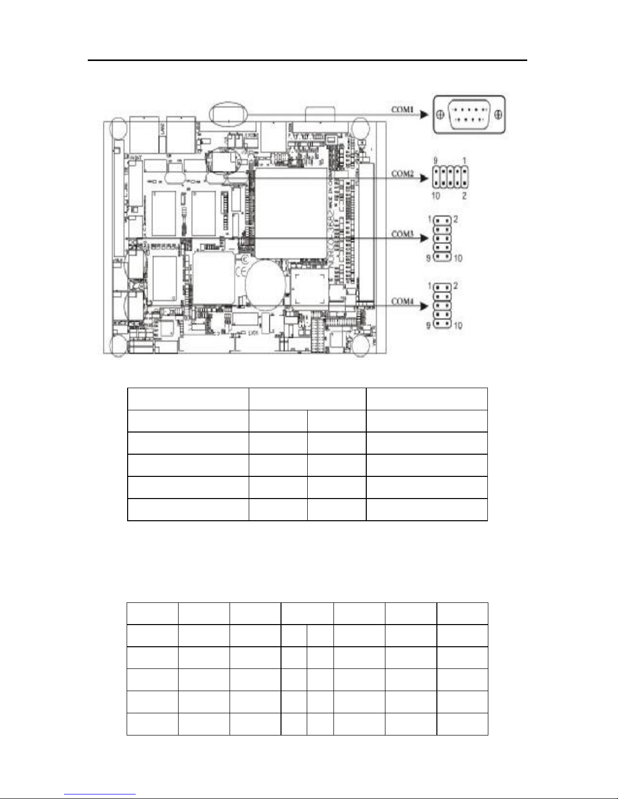
2.3.3 Serial Ports (COM1/2/3/4)
Board provides 6*serial ports. COM1 adopts DB9 interface, COM2/3/4 need convert
cable (DB10 to DB9) to connect external devices. COM1-4 support RS-232 mode,
while COM2 supports RS422/485. COM2-COM4 adopt 2x5Header interface.
Page 21
EMB-3682 AMD LX700, support VGA+LVDS or TTL
- 13 -
COM1 ->RS232:
DEFINE PIN#
DEFINE
HDCD#1
1 6
HDSR#1
HSIN#1
2 7
HRTS#1
HSOUT1
3 8
HCTS#1
HDTR#1
4 9
HRI#1
GND
5
COM2 ->RS232/422/485
COM2 can be set as RS232/RS422/RS485,Pin define as follow:
RS485 RS422 RS232
PIN# RS232 RS422 RS485
DATE-
TX- DCD 1 2
DSR NC NC
DATE+
TX+ RXD 3 4
RTS NC NC
NC RX+ TXD 5 6
CTS NC NC
NC RX- DTR 7 8
RI NC NC
GND GND GND 9 10
GND GND GND
Page 22
EMB-3682 AMD LX700, support VGA+LVDS or TTL
- 14 -
COM3/4 ->RS232
DEFINE PIN#
DEFINE
HDCD
1 2
HDSR
HSIN
3 4
HRTS
HSOUT
5 6
HCTS
HDTR
7 8
HRI
GND
9 10
GND
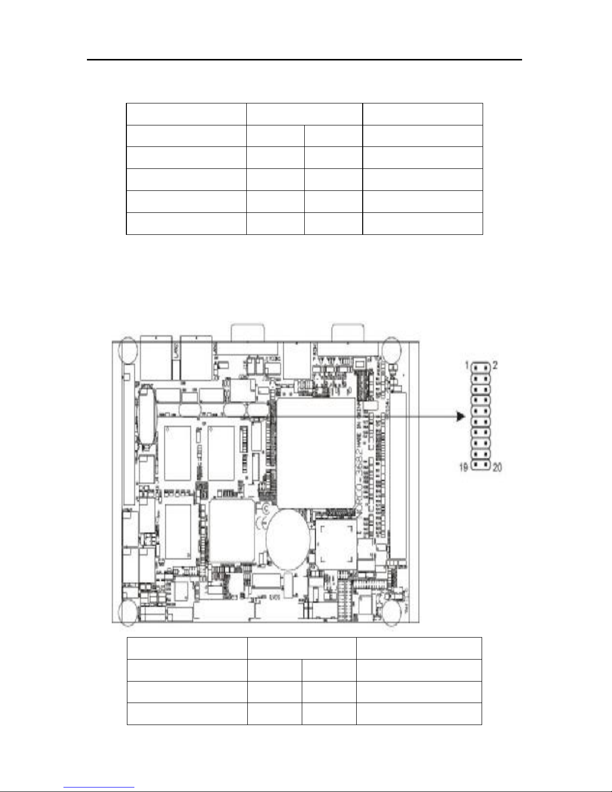
2.3.4 Parallel Port (PRINT)
Onboard one 2x10Header parallel interface to connect parallel devices, usually for
Printer
DEFINE PIN#
DEFINE
T_STB# 1 2 T_AFD#
PDQO 3 4 T_ERR#
PDQ1 5 6 T_INIT#
Page 23
EMB-3682 AMD LX700, support VGA+LVDS or TTL
- 15 -
PDQ2 7 8 T_SLIN#
PDQ3 9 10 GND
PDQ4 11 12 GND
PDQ5 13 14 GND
PDQ6 15 16 T_BUSY
PDQ7 17 18 T_PE
T_ACK# 19 20 T_SLCT
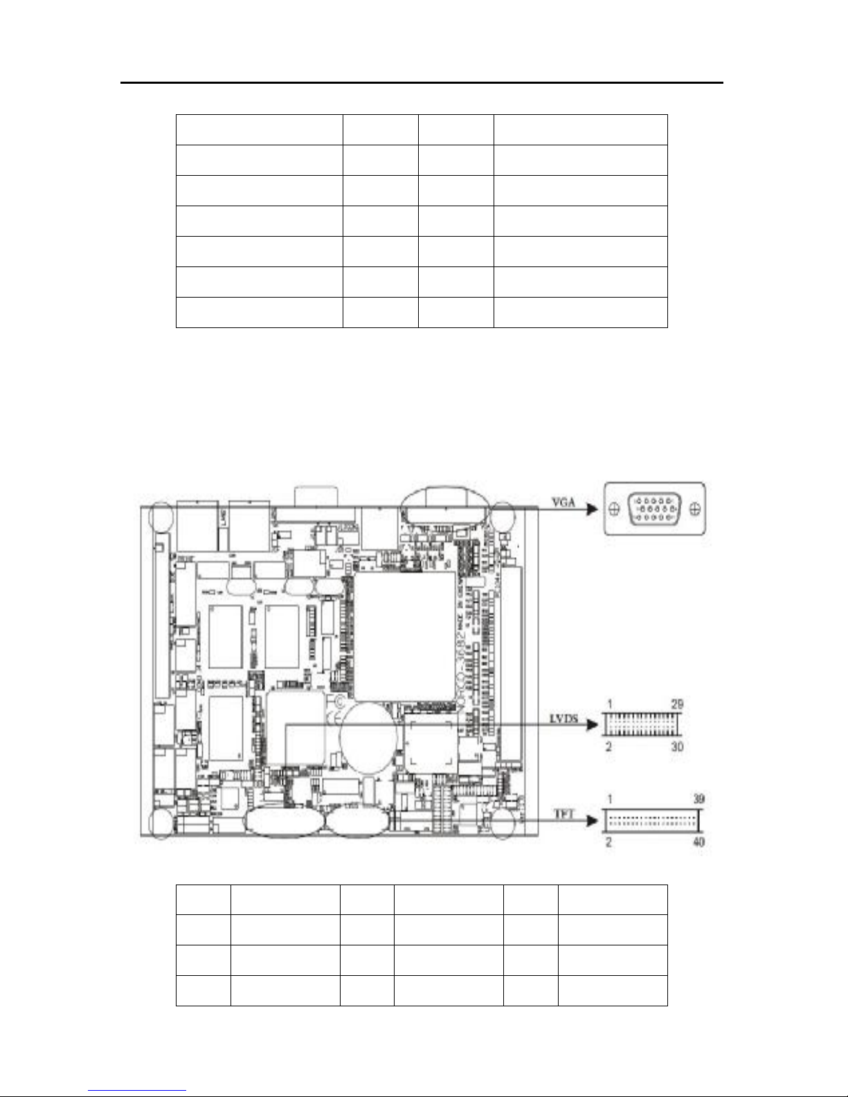
2.3.5 Display Interface (VGA, LVDS, TFT)
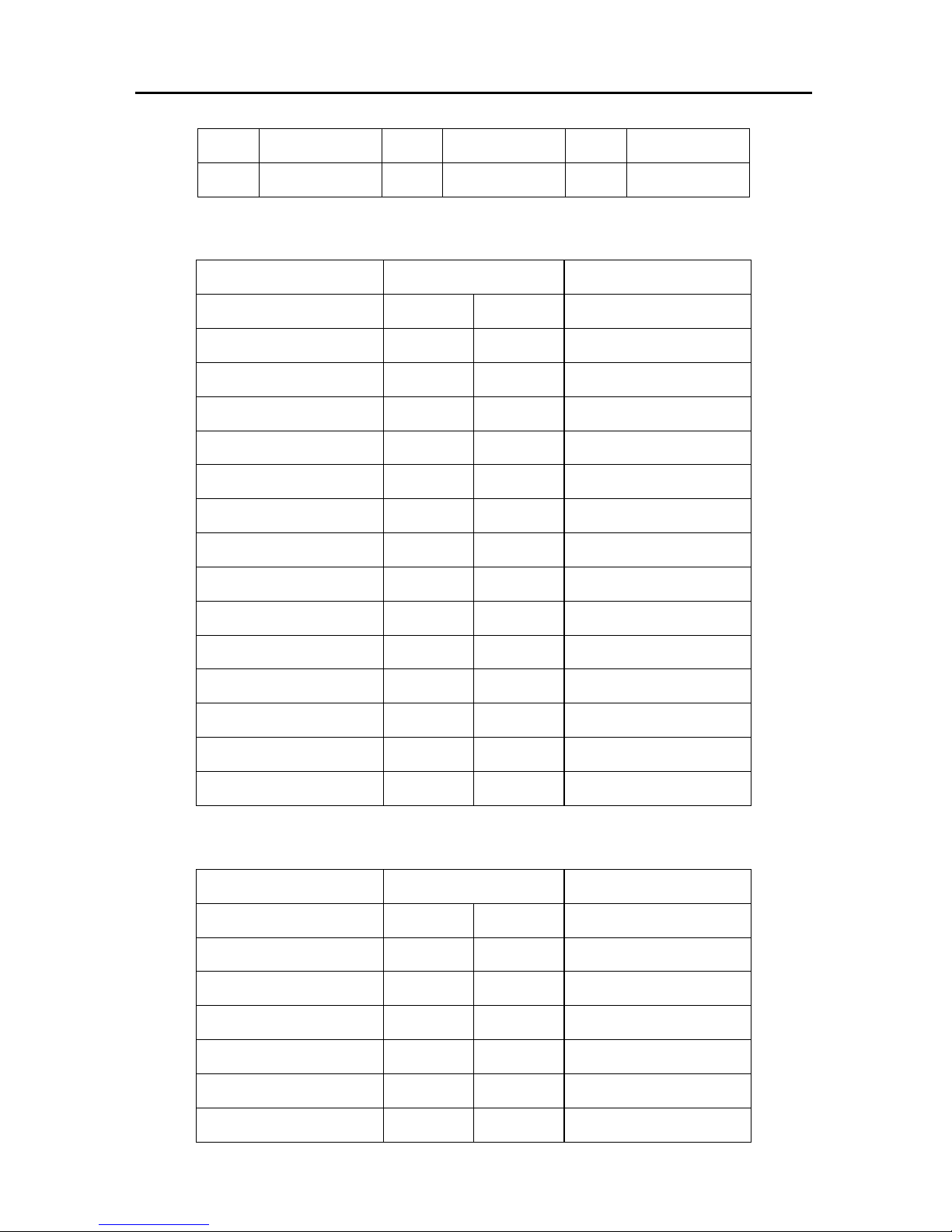
Board provides 3*display interfaces; Standard 15PIN VGA can be connected with
VGA-compatible devices, such as CRT display, etc. LVDS and TFT can be
connected to LCD display directly.
VGA:
PIN
DEFINE
PIN
DEFINE
PIN
DEFINE
1 RED 6 GND 11 NC
2 GREEN 7 GND 12 SDA
3 BLUE 8 GND 13 HSYNC
Page 24
EMB-3682 AMD LX700, support VGA+LVDS or TTL
- 16 -
4 NC 9 NC 14 VSYNC
5 GND 10 GND 15 CLK
LVDS:
DEFINE PIN#
DEFINE
VDD 1 2 VDD
GND 3 4 GND
YAM0 5 6 YBM0
YAP0 7 8 YBP0
GND 9 10 GND
YAM1 11 12 YBM1
YAP1 13 14 YBP1
GND 15 16 GND
YAM2 17 18 YBM2
YAP2 19 20 YBP2
GND 21 22 GND
CLKAM 23 24 CLKBM
CLKAP 25 26 CLKBP
GND 27 28 GND
DDCPDATA 29 30 DDCPCLK
TFT:
DEFINE PIN#
DEFINE
12V_VDD
1 2
12V_VDD
GND
3 4
GND
VCC_LCD
5 6
VCC_LCD
NC
7 8
GND
TFT_B0
9 10
TFT_B1
TFT_B2
11 12
TFT_B3
TFT_B4
13 14
TFT_B5
Page 25
EMB-3682 AMD LX700, support VGA+LVDS or TTL
- 17 -
TFT_B6
15 16
TFT_B7
TFT_G0
17 18
TFT_G1
TFT_G2
19 20
TFT_G3
TFT_G4
21 22
TFT_G5
TFT_G6
23 24
TFT_G7
TFT_R0
25 26
TFT_R1
TFT_R2
27 28
TFT_R3
TFT_R4
29 30
TFT_R5
TFT_R6
31 32
TFT_R7
GND
33 34
GND
TFTCLK
35 36
VSYNC-C
VSYNC
37 38
HSYNC-C
GND
39 40
DISPEN
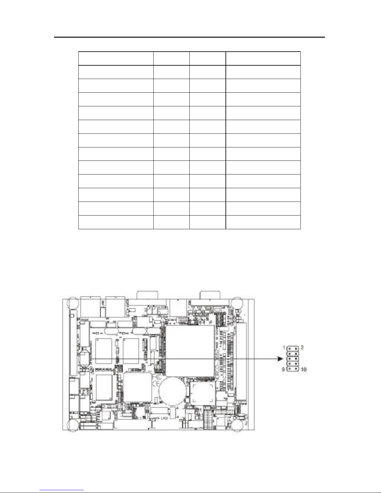
2.3.6 LCD Backlight Control (J4)
J4 is used to connect LCD devices, providing control over the backlight luminance of
LVDS and TFT via BIOS setup
Page 26
EMB-3682 AMD LX700, support VGA+LVDS or TTL
- 18 -
DEFINE PIN# DEFINE
12V 1 2 VCC_LCD
DISPEN 3 4 GP34
GND 5 6 GND
12V_LCD 7 8
FANPWM1
VCC5 9 10
FANPWM2
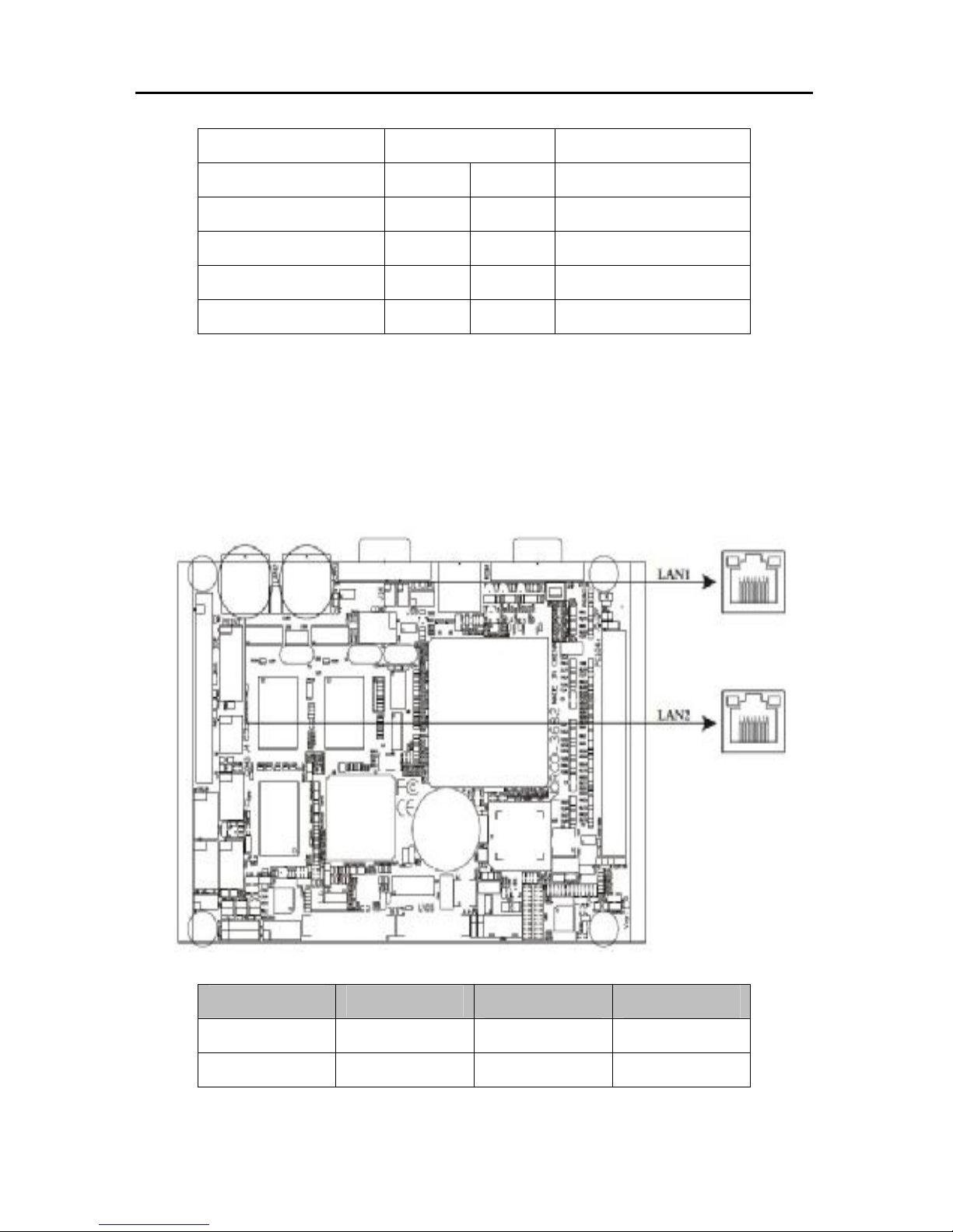
2.3.7 Ehternet Port (LAN1/2)
Board provides 2*Gigabite Ethernet Port (RJ45). Both sides of the port has one LED:
Left one represents data transfer status, while right one represents network link
status.
Link (yellow)
Network
Active Data
Light on effective Light on Yes
Light off Non-effective
Light off No
Page 27
EMB-3682 AMD LX700, support VGA+LVDS or TTL
- 19 -
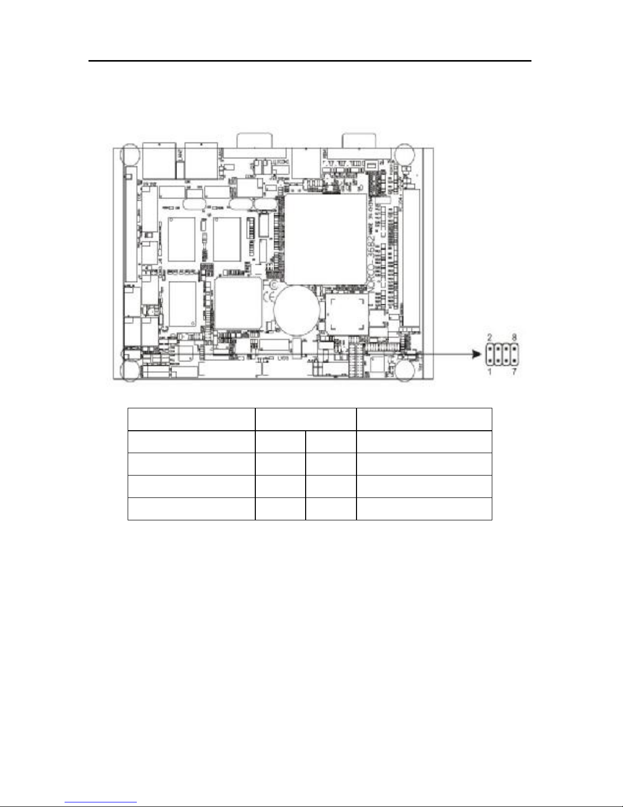
2.3.8 GPIO (JGP)
DEFINE PIN# DEFINE
GPIO 16 1 2 VCC5
GPIO 14 3 4 GPIO 15
GPIO 12 5 6 GPIO 17
GND 7 8 GPIO 23
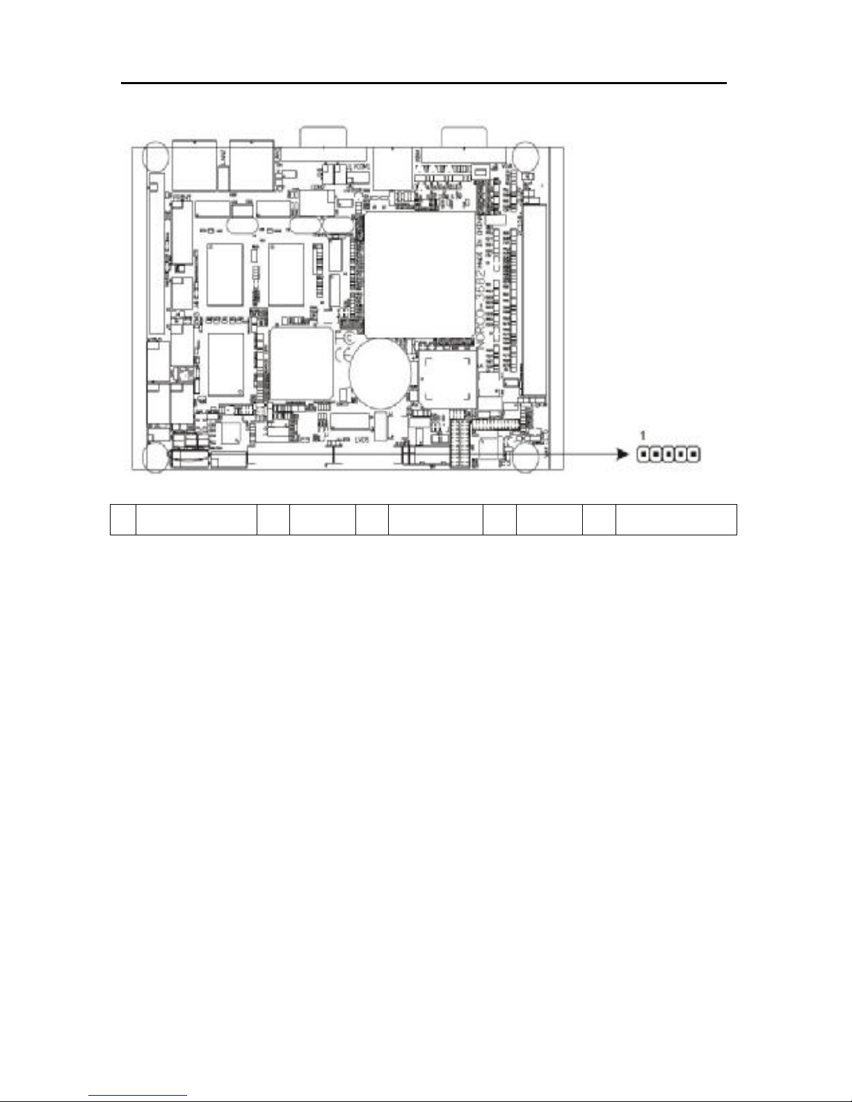
2.3.9 Audio Interface (J9)
Board provides one 5 Header Audio interface, providing Speak-out and Mic-in
Function.
Page 28
EMB-3682 AMD LX700, support VGA+LVDS or TTL
- 20 -
1 SPKOUT_L 2
GND
3
MIC_IN 4
GND
5
SPKOUT_R
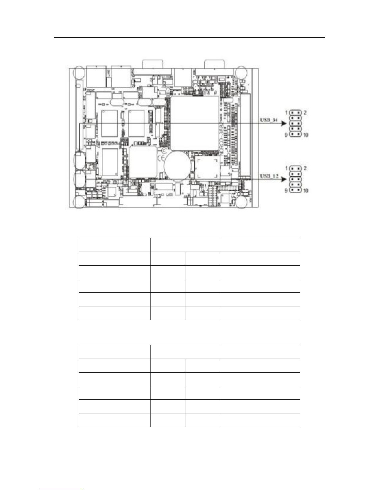
2.3.10 USB Ports (USB_12, USB_34)
Board provides 2*2x5Pin USB ports (USB_12, USB_34), All the USB ports can be
activated or closed via BIOS configuration. both need convert cable to be connected
with standard USB jack.
Page 29
EMB-3682 AMD LX700, support VGA+LVDS or TTL
- 21 -
USB_12
DEFINE PIN# DEFINE
+5V 1 2 GND
USB Data0- 3 4 GND
USB Data0+ 5 6 USB Data1+
GND 7 8 USB Data1GND 9 10 +5V
USB_34
DEFINE PIN# DEFINE
+5V 1 2 GND
USB Data2- 3 4 GND
USB Data2+ 5 6 USB Data3+
GND 7 8 USB Data3GND 9 10 +5V
Page 30
EMB-3682 AMD LX700, support VGA+LVDS or TTL
- 22 -
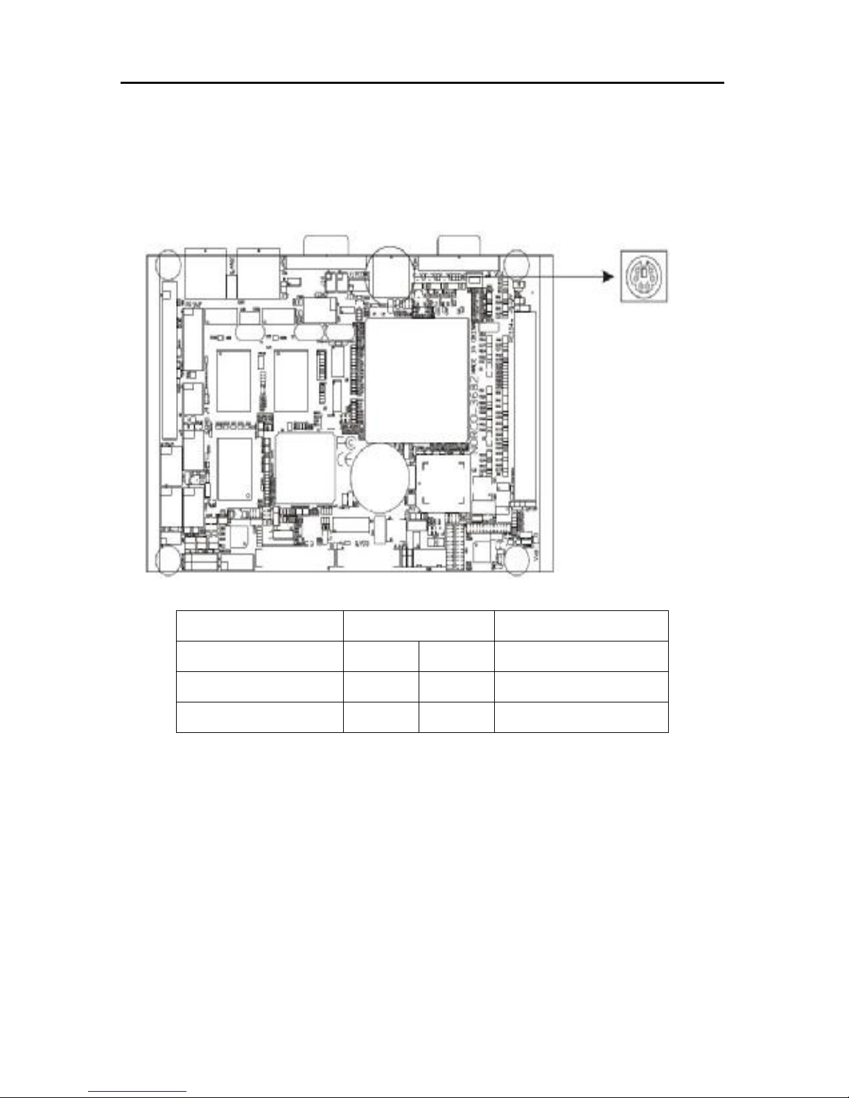
2.3.11 KB/MS Connector(KBM)
6 Pins PS/2 port for KB/MS, need to be connected by Y- shape convert cable to
connect keyboard and mouse.
DEFINE PIN#
DEFINE
KEYBOARD_DATA
1 2 MOUSE_DATA
GND 3 4 +5V
KEYBOARD_CLK 5 6 MOUSE_CLK
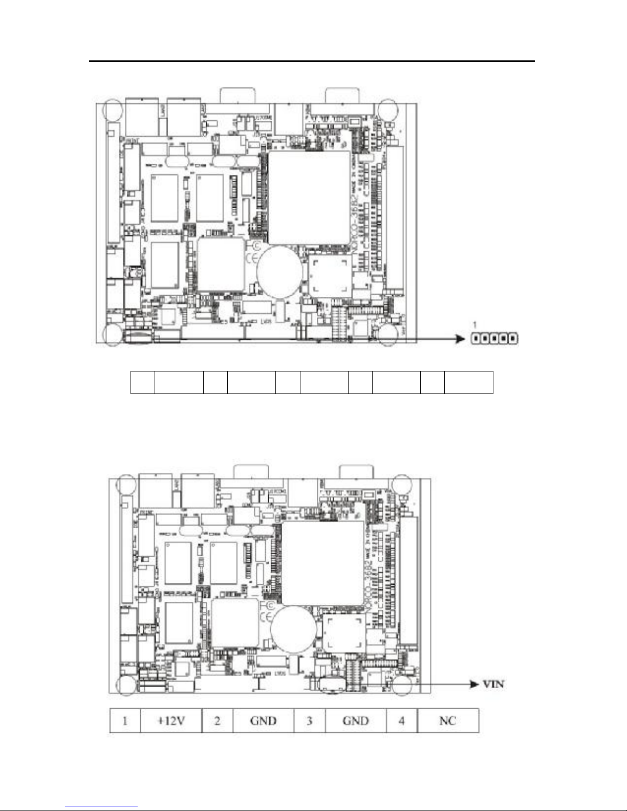
2.3.12 IrDA Interface (IrDA)
This board provides an IrDA connector, support data transmitting by infrared ray.
Page 31
EMB-3682 AMD LX700, support VGA+LVDS or TTL
- 23 -
1
+5V
2
NC 3 IRRX 4
GND
5
IRTX
2.3.13 Power Interface (VIN)
Page 32
EMB-3682 AMD LX700, support VGA+LVDS or TTL
- 24 -
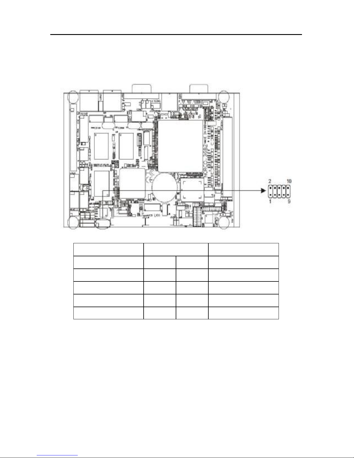
2.3.14 Front Panel Connector (J1)
J1 is used to connect the function buttons or LED on front panel.
DEFINE PIN# DEFINE
PWRBTN# 1 2 GND
HDLED 3 4 VCC3
BUZZDATA 5 6 VCC5
RST 7 8
GND
KEYLOCK 9 10 GND
1) Power LED pins (pin1, pin2 for VCC)
Connecting system power LED cable with these pins, when system power switch on,
power LED on;When system power switches off, power LED off.
2) IDE LED Pins (pin 3, pin 4 for HDD LED)
As a rule, there is a IDE LED on the panel of chassis, while IDE device(like hard Disk)
is reading or writing(no matter which IDE device), LED will flash, shows that IDE
Device is running. Connect IDE LED with these pins.
3) Buzzer Pins (pin 5, pin 6 for BUZZ)
Page 33
EMB-3682 AMD LX700, support VGA+LVDS or TTL
- 25 -
External Buzzer Pins. When system boots or system encounters malfunctions,
Buzzer will sound differently.
4) Reset Button Pins (pin7, pin 8 for RESET)
Connect this pins with RESET switch on panel of chassis with cable. When system
fails, this function can enable the system to work again without turning off the power
supply, which will also prolong the system lifecycle.
5) KEYLOCK Pins(pin9&pin10 for KEYLOCK)
Connecting keylock function-control cable with these pins, then it can carry out
keylock function.
2.3.15 Memory Socket (DDR)
Rear panel provides one 200Pin DDR SO DIMM memory socket, supporting 333/400/MHz
DDR memory, up to 1GB.
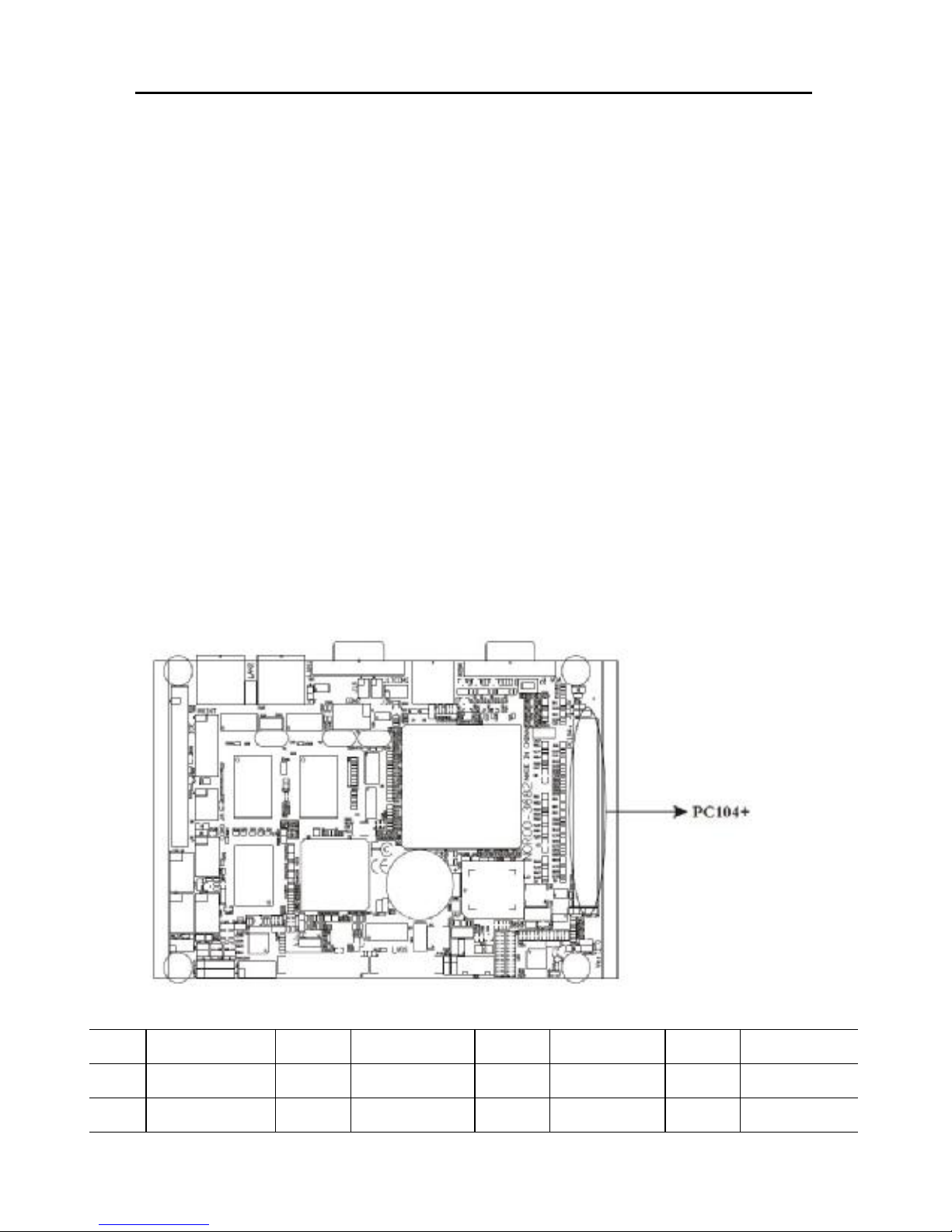
2.3.16 PC 104 Plus Socket (PC 104+)
PIN#
DEFINE PIN# DEFINE PIN# DEFINE PIN# DEFINE
A1 GND/5V B1 NC C1 +5V_4 D1 AD00
A2 VI/O_0 B2 AD02 C2 AD01 D2 +5V_7
Page 34

EMB-3682 AMD LX700, support VGA+LVDS or TTL
- 26 -
A3 AD05 B3 GND_6 C3 AD04 D3 AD03
A4 C/BE#0 B4 AD07 C4 GND_11 D4 AD06
A5 GND_0 B5 AD09 C5 AD08 D5 GND_17
A6 AD11 B6 VI/O_1 C6 AD10 D6 M66EN
A7 AD14 B7 AD13 C7 GND_12 D7 AD12
A8 +3.3V_0 B8 C/BE#1 C8 AD15 D8 +3.3V_7
A9 SERR# B9 GND_7 C9 SB#0 D9 PAR
A10
GND_1 B10 PERR# C10 +3.3V_5 D10 SDONE
A11
STOP# B11 +3.3V_3 C11 LOCK# D11 GND_18
A12
+3.3V_1 B12 TRDY# C12 GND_13 D12 DEVSEL
A13
FRAME# B13 GND_8 C13 IRDY# D13 +3.3V_8
A14
GND_2 B14 AD16 C14 +3.3V_6 D14 C/BE#2
A15
AD18 B15 +3.3V_4 C15 AD17 D15 GND_19
A16
AD21 B16 AD20 C16 GND_14 D16 AD19
A17
+3.3V_2 B17 AD23 C17 AD22 D17 +3.3V_9
A18
IDSEL0 B18 GND_9 C18 IDSEL1 D18 IDSEL2
A19
AD24 B19 C/BE#3 C19 VI/O_3 D19 IDSEL3
A20
GND_3 B20 AD26 C20 AD25 D20 GND_20
A21
AD29 B21 +5V_2 C21 AD28 D21 AD27
A22
+5V_0 B22 AD30 C22 GND_15 D22 AD31
A23
REQ#0 B23 GND_10 C23 REQ#1 D23 VI/O_4
A24
GND_4 B24 REQ#2 C24 +5V_5 D24 GNT#0
A25
GNT#1 B25 VI/O_2 C25 GNT#2 D25 GND_21
A26
+5V_1 B26 CLK0 C26 GND_16 D26 CLK1
A27
CLK2 B27 +5V_3 C27 CLK3 D27 GND_22
A28
GND_5 B28 INTD# C28 +5V_6 D28 RST#
A29
+12V B29 INTA# C29 INTB# D29 INTC#
A30
-12V B30 NC C30 NC D30 GND
Page 35

EMB-3682 AMD LX700, support VGA+LVDS or TTL
- 27 -
Chapter 3
BIOS Setup
Page 36

EMB-3682 AMD LX700, support VGA+LVDS or TTL
27
Chapter 3 BIOS Setup
3.1 BIOS Upgrading
BIOS functions as a bridge connecting hardware and operating system. Hardware
and software are upgrading all the time, so when your system goes wrong, for
example, your system can not support the newest CPU, you need to upgrade BIOS
to keep up with the latest technology.
Use boot disk to load DOS, run Afudos.exe to update the BIOS (eg. XXXX.ROM)
into the Flash IC.
Order format: A:\ Afudos XXXX.ROM
If you need to add other parameters after the order format, please add <space>/?
Remarks:
1. Upgrading BISO may cause your system crash, so please operate carefully.
2. Please use the upgrading program in the CD-ROM provided by us or download
from our website
3. Please do not power off or reboot the system when upgrading, otherwise, the
BIOS maybe be damaged.
4. Please backup your BIOS before upgrading
3.2 AMI BIOS Description
When the computer is power on, BIOS will conduct self-diagnosis (POST)to its
hardware on motherboard and configure hardware parameter, finally the operating
system will take control. BIOS is the communication bridge between hardware and
O/S. Correct configuration of BIOS is critical for maintaining system stability.
3.3 BIOS Parameter Configuration
Power on your computer. After finishing the self-diagnosis, following message
will show on the screen:
Del->SETUP please press “DEL”, then it will enter BIOS setup interface.
1. Power on or Restart computer, self-detection information will show:
Page 37
EMB-3682 AMD LX700, support VGA+LVDS or TTL
28
2. When message "Press <Del> to enter setup" shows up on screen, please press
<Del> to enter into BIOS configuration program..
3. Use the “←↑→↓”to choose the options that your want to modify, press <Enter>
and show the sub-menu.
4. Use the “←↑→↓”and <Enter> to modify the value of the options that you chosen
5. At any time, press<Esc> can back to the father-menu.
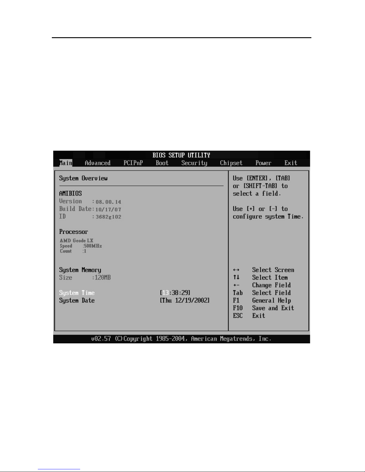
3.4 Main Menu
AMI BIOS (Read only)
BIOS information: such as Version, BIOS ID and Build Date.
Processor (Read only)
CPU information: such as processor type and speed.
System Memory (Read only)
System Memory Size
Page 38
EMB-3682 AMD LX700, support VGA+LVDS or TTL
29
System Time
Format: Hour/Minute/Second
System Date
Format: Day/Month/Date/Year ;< Day><Month><Date><Year> can be set by users.
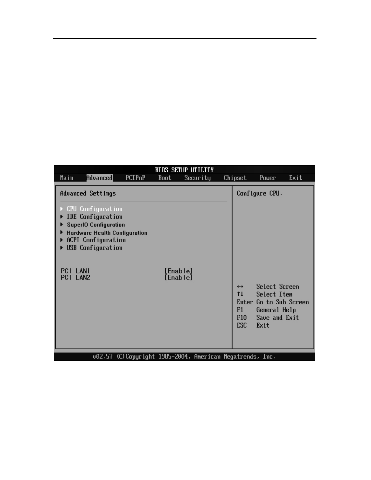
3.5 Advanced Menu
PCI LAN
[Enable]: Open onboard PCI LAN Card
[Disable]: Close onboard PCI LAN Card
Page 39
EMB-3682 AMD LX700, support VGA+LVDS or TTL
30
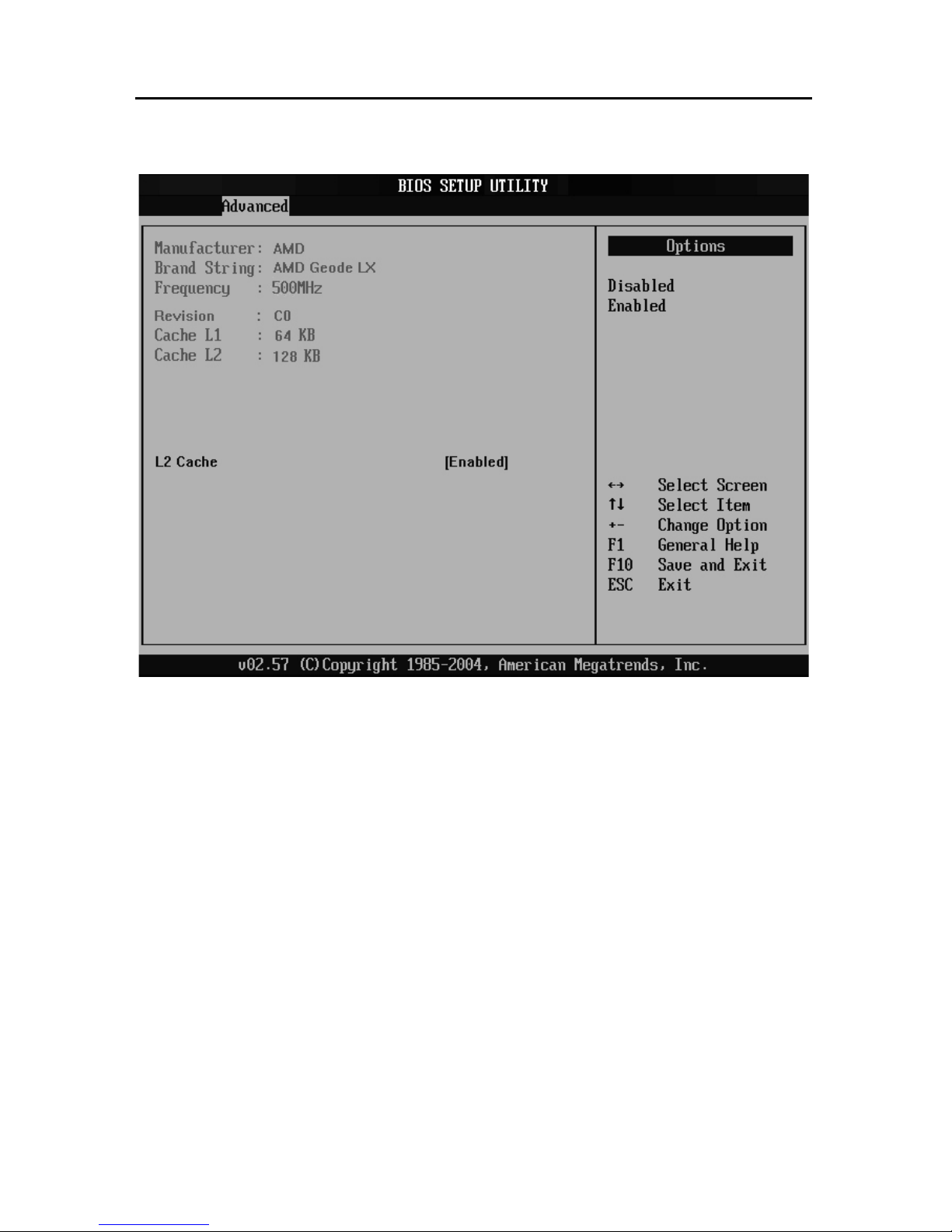
3.5.1 CPU Configuration
CPU Configuration
This option includes detailed CPU information: Vendor, Type, Frequency, L1 cache,
L2 cache…
L2 Cache
Choose whether to open L2 Cache or not, <Enabled: open>, <Disabled: close>.
Page 40
EMB-3682 AMD LX700, support VGA+LVDS or TTL
31
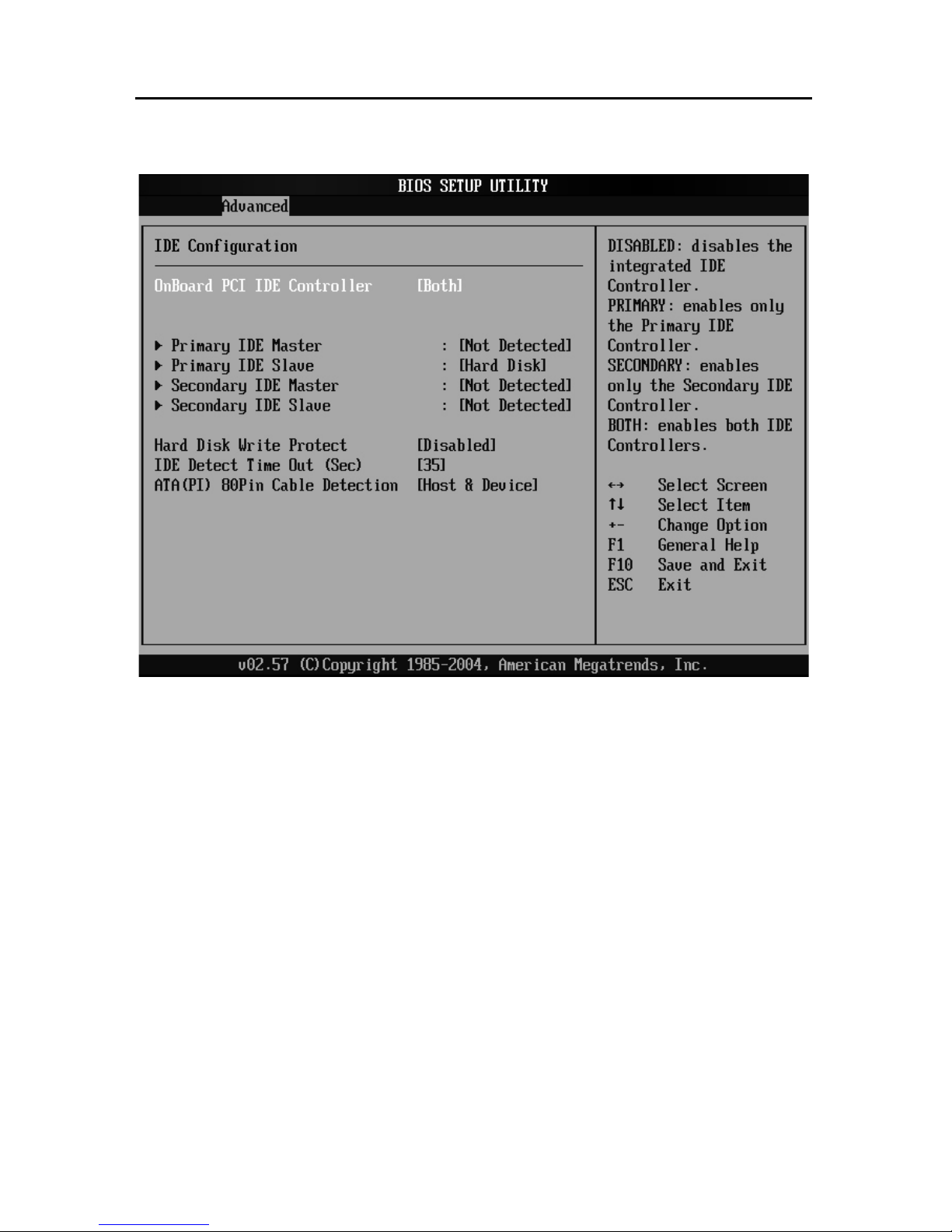
3.5.2 IDE Configuration
Onboard PCI IDE Controller
Setting IDE port as <Disabled> will close all IDE ports; <Primary> will enable the
First IDE port; <Secondary> will enable the Second IDE port; <Both> will enable
both two IDE ports.
Primary/Secondary IDE Master/Slave
These four options are used to choose the type of IDE devices, including the
following seven options “Type”, “LBA/Large Mode”, “Block (Multi-Sector Transfer)”,
“PIO Mode”, “DMA Mode”, “S.M.A.R.T.” ( Self-Monitoring, Analysis and Reporting
Technology) , “32Bit Data Transfer”. [Auto] is recommended, the system will
auto-detect the devices, if you want Config by yourself, make sure all parameters of
the HDD support this mode first.
Hard Disk Write Protect
Setup HDD Write Protect function :< Enabled> Write Protect, HDD read only:
Page 41
EMB-3682 AMD LX700, support VGA+LVDS or TTL
32
<Disabled> write protect, HDD can write or read.
IDE Detect Time Out(Sec)
Setup for BIOS searching IDE device in appointed time (by seconds).
ATA( PI) 80Pin Cable Detection
Setup to detect ATA (PI) 80pin cable: 80pin ATA cable is for Ultra ATA/66, Ultra
ATA/100 and Ultra ATA/133 .Standard cable is 40pin, which can not support high
transfer rate. These two cables is pin compatible.
<Host & Device> will consult the cable type of both IDE controller and IDE disk driver.
Also it is default value. <Host> use the cable type used by IDE controller;
<Device> use the cable type used by IDE disk driver.
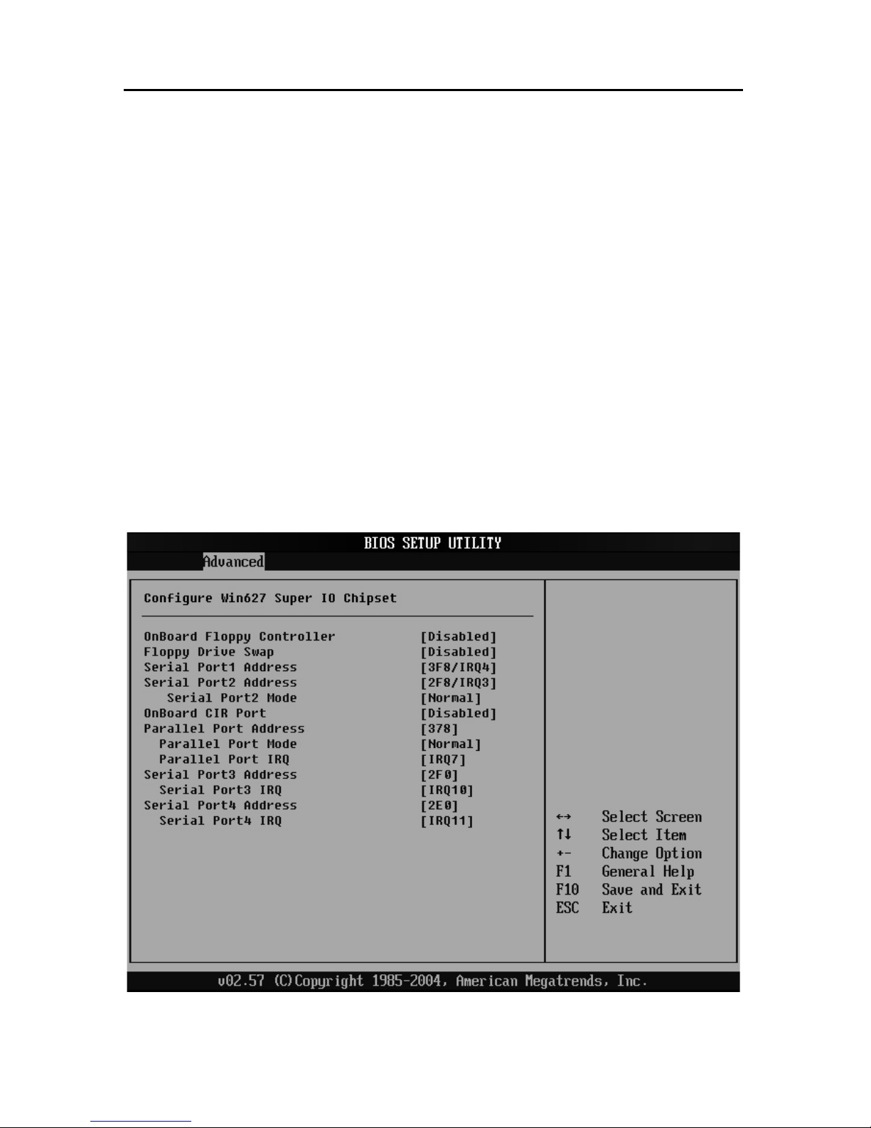
3.5.3 Supper I/O Configuration
Onboard Floppy Controller
[Enable] Open floppy drive
Page 42

EMB-3682 AMD LX700, support VGA+LVDS or TTL
33
[Disable] Close Floppy Drive
Floppy Driver Swap
Setup exchange volume label of floppy device: A and B.
<Enabled>: Exchange lvolume label in DOS mode.
<Disabled>: Disable exchange
Serial Port1 Address
This option is used to config interrupt and address of serial port 1. Default set is
recommended.
Serial Port2 Address
This option is used to config interrupt and address of serial port 2. Default set is
recommended.
Serial Port2 Mode
This option is used to configure serial port 2 mode.The optimal default set as
[Normal].
If connecting infrared communications devices, then config as IrDA or ASK IR.
Onboard CIR Port
<Enabled>: Open.
<Disabled>: Close
Parallel Port Address
Recommended default setting
Parallel Port Mode
This is used to choose Parallel Port Transmission mode
( Bi-Dir/ECP/EPP/ECP&EPP/Normal). Default as [Normal]
Parallel Port IRQ
This is used to choose Parallel Port IRQ. Recommended default setting.
Page 43
EMB-3682 AMD LX700, support VGA+LVDS or TTL
34
Serial Prot3/4 Address
This is used to config the interrupt and address of serial port 3 &4. Default set
recommended.
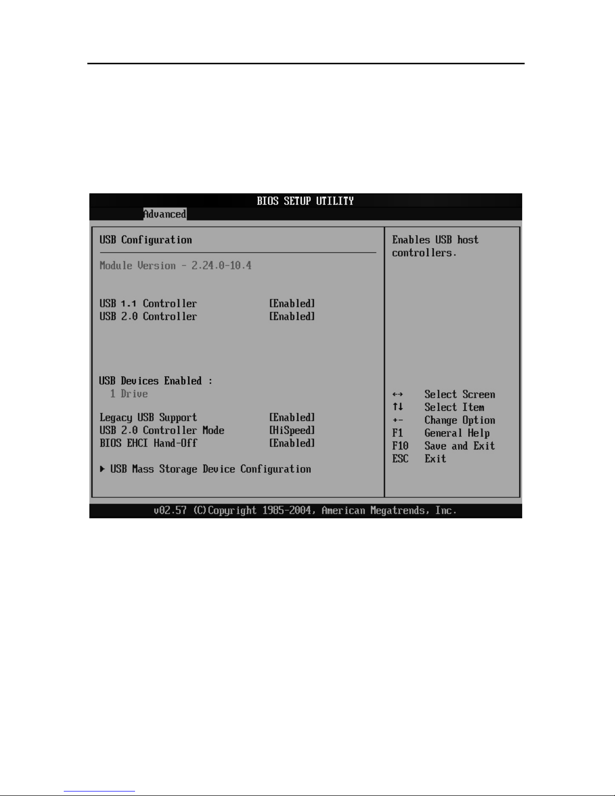
3.5.4 USB Configuration
USB 1.1 Controller
This option is used to open or close the USB1.1 port. [Enable] for open; [Disable] for
close.
USB2.0 Controller
This option is used to open or close the USB2.0 port. [Enable] for open; [Disable] for
close.
Legacy USB Support
It configures to support USB device in DOS mode: such as USB Flash Disk, USB
keyboard, ect, then select<Enabled> or<Auto>. If not , select < Disabled>.
Page 44
EMB-3682 AMD LX700, support VGA+LVDS or TTL
35
USB2.0 Controller Mode
This option is to choose USB2.0 port mode, Available after “USB2.0 Controller”
enabled
<FullSpeed>: the speed of USB2.0
<HiSpeed>: the speed of USB1.1
BIOS EHCI Hand-off
<Enabled>: When enter OS, BIOS auto close.
<Disabled>:When enter OS, BIOS closed by OS.
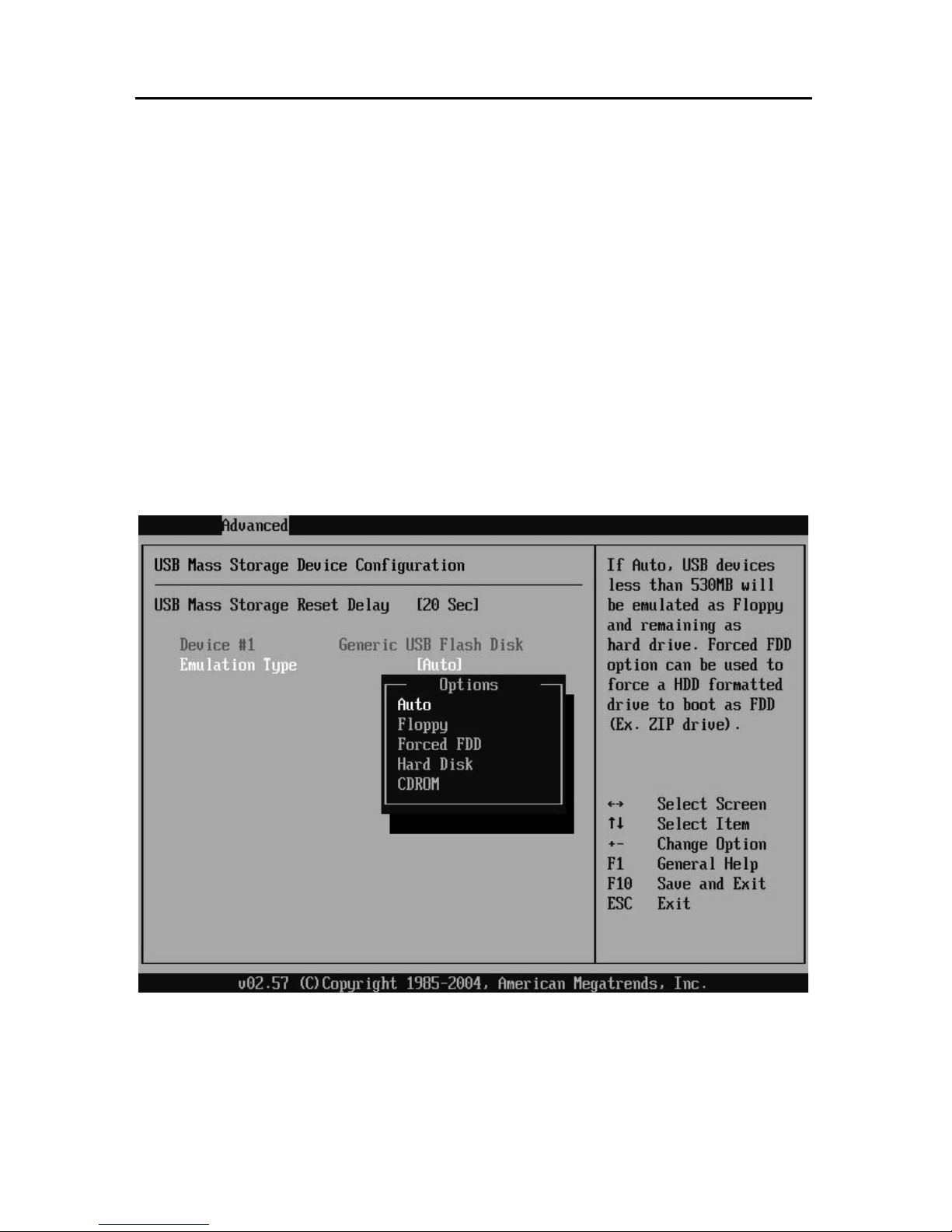
3.5.5 USB Mass Storage Device Configuration
Setup the emulation mode when use U disk to boot up system. Mode:
Auto/Floppy/Forced FDD/Hard Disk/CDROM. <AUTO> for default.
Page 45
EMB-3682 AMD LX700, support VGA+LVDS or TTL
36
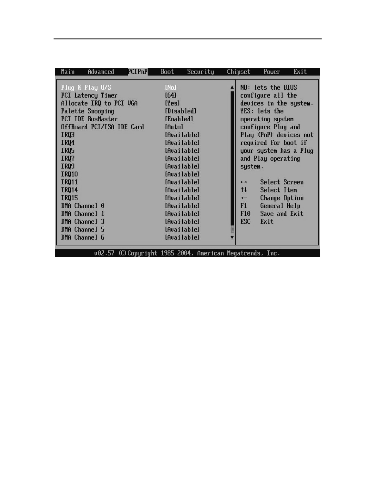
3.5.6 PCI PnP Menu
Plug & Play O/S
If the operating system supports PnP, then choose [YES], therefore, the operating
system will auto modify the setting of interrrupt, I/O and DMA. If O/S is without
PnP, then choose [NO], therefore, O/S will allocate the resources to all devices.
PCI Latency Timer
This option is to set the latency time of all PCI devices on the PCI bus.The Unit is
PCI clock cycle.
Allocate IRQ to PCI VGA
<Yes> Allocate IRQ to PCI VGA adapter
<No> PCI VGA adapter forbidden
Palette Snooping
<Yes>: Enable VGA adapter based on ISA chipset. (Before change default set,
please read the VGA card manual)
Page 46

EMB-3682 AMD LX700, support VGA+LVDS or TTL
37
<No>: Disabled.
PCI IDE BusMaster
<Enabled>: Open BusMaster function, which can accelerate PCI IDE device transfer
speed.
<Disabled>: Close BusMaster function.
OffBoard PCI/ISA IDE Card
This item is to set offboard PCI and ISA IDE card. If this item is set as [AUTO], the
system will do auto-detection. You can also assign the slot which the cards are
resided.
DMA Channel 0-7, IRQ3-15
<PCI/PnP>: When BIOS detect PnP card, will allocate IRQ/DMA from all resources
which set as PCI/PnP
<ISA/EISA>: BIOS will not auto-config
Default set as< PCI/PnP>
IRQ3-15
[Available]: Specified IRQ is available to be used by PCI/PnP devices.
[Reserved]: Specified IRQ is reserved for use by Legacy ISA devices
Page 47
EMB-3682 AMD LX700, support VGA+LVDS or TTL
38
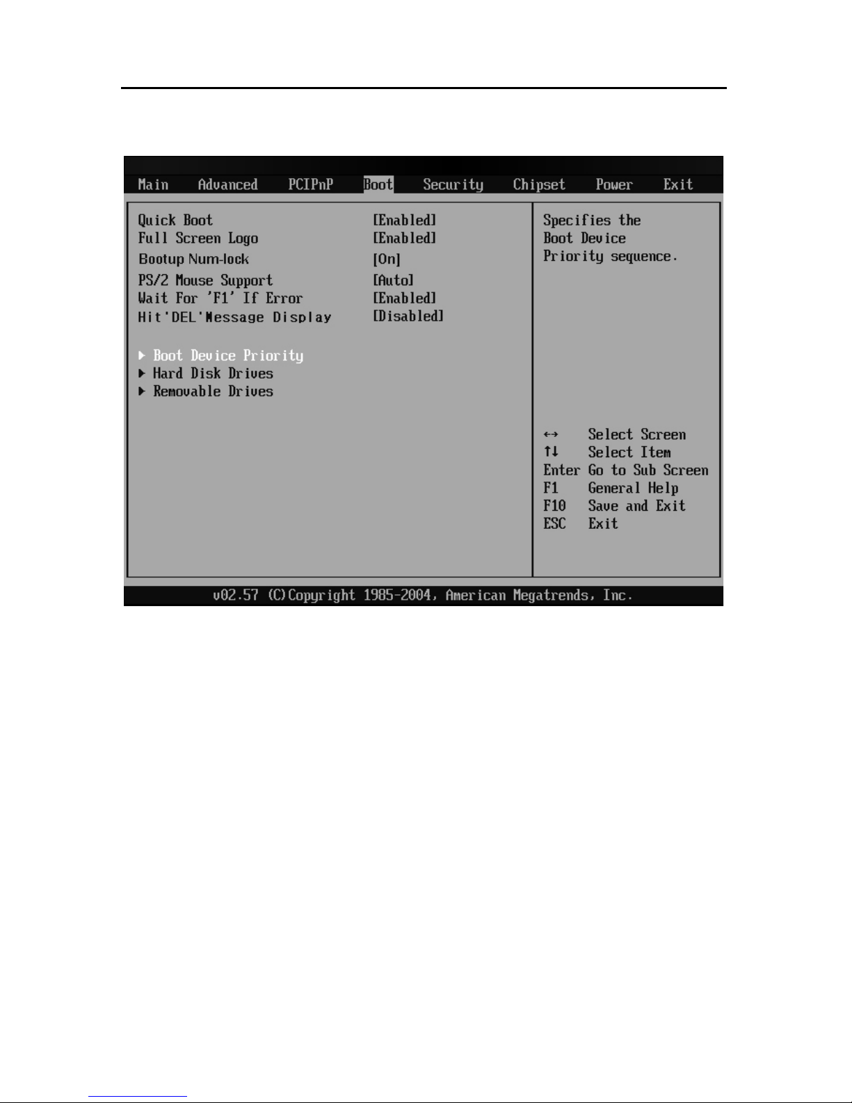
3.6 Boot Menu
Quick Boot
<Enabled>: BIOS will skip self-detection and accelerate POST
<Disabled>: After BIOS detecttion load Windows O/S.
Full Screen Logo
<Enabled>: Display LOGO by user define
<Disabled>:Display default BIOS LOGO
Boot Up Num-Lock
This item is to allow you select the Number Lock status when the system is power on.
By default, [ON] is set to allow the number lock open when system start; if [OFF], the
number pad is set as cursor controlling
PS/2 Mouse Support
This option is used to enable or disable the availability of PS/2 mouse port support.
Page 48

EMB-3682 AMD LX700, support VGA+LVDS or TTL
39
<Enabled>: PS/2 Mouser port supported
<Disabled>: PS/2 Mouser port unsupported
<Auto>: Auto detection to the system. If it has PS/2 mouse port, the function is
supported.
Wait For “F1” If Error
Definition of this function: In the case of any errors found in the system self-detection,
it is waiting for the user to press F1 key, then the system will go on operation.
<Enable>: This function is enabled and when system error occurs, the prompt
information such as “Press ‘F1’ to resume” or “Press ‘F1’ to Set up” will be displayed.
Users will wait for ‘F1’ to continue.
<Disable> System will show no prompt information and will directly load Windows
O/S.
Hit “DEL” Message Display
If set as [Enabled], the boot-up screen will show hint as Hit "Del" if you want to run
setup". If set as [Disabled], the hint will not be shown on the screen when system is
booted. In most occasions, this item is set as [Enabled].
Boot Device Priority
Press “Enter” will show following sub-menu:
1st Boot Device
2nd Boot Device
System will detect device by this priority until find an available boot device then boot
from it (Boot devices support Removable Drive or Hard Disk Drive).
Hard Disk Drives
Boot device set for HDD. If multi- HDD are connected, user must set up their priority.
The HDD of the highest priority will be displayed in “Boot Device Priority”
Removable Drives
Boot device set for Removable Device: include U Disk, CDROM, Floppy Disk.
If has mutil-device , must set up priority, The Highest Priority HDD will display in
Page 49
EMB-3682 AMD LX700, support VGA+LVDS or TTL
40
“Boot Device Priority”
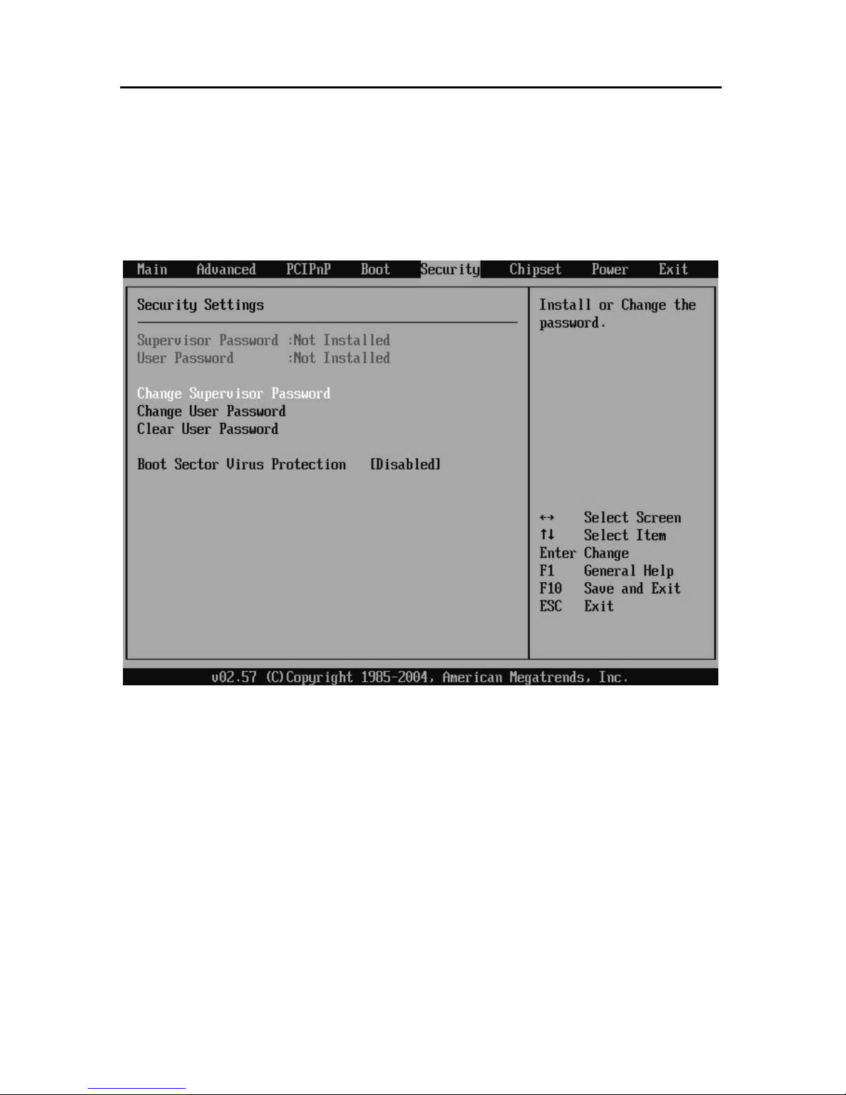
3.7 Security Menu
Supervisor Password (Read Only)
If set up supervisor password, system will display [Installed]. If not, it will display [Not
Installed].
User Password (Read Only)
If set up user password, system will display [Installed]. If not , it will display [Not
Installed].
Change Supervisor Password
Press ‘Enter ‘ under this option, then enter into the sub-menu to change the
supervisor’s password
Page 50

EMB-3682 AMD LX700, support VGA+LVDS or TTL
41
Change User Password
Press ‘Enter’ under this option and enter into the sub-menu to change the user ‘s
password.
Boot Sector Virus Protection
<Enabled>:Boot sector virus protection will be activated. When execute Disk format
or Write the Bootable section instruction, BIOS will send a warning.
Example as below:
Boot Sector Write!
Possible VIRUS: Continue (Y/N)? _
(Must press much ‘N’ and skip up)
Format!!!
Possible VIRUS: Continue (Y/N)? _
(Must press much ‘N’ and skip up)
[Disabled]: close this function.
Page 51
EMB-3682 AMD LX700, support VGA+LVDS or TTL
42
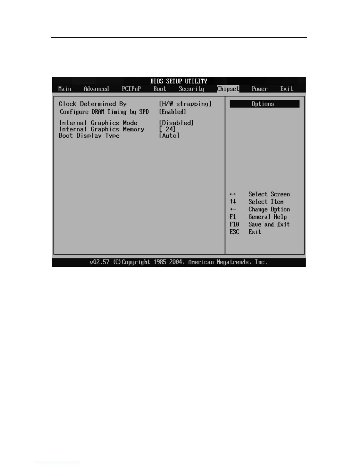
3.8 Chipset Menu
Clock Determined By
This option is used to setup CPU frequency
[H/W strapping]: BIOS automatically configures CPU and memory frequency in
accordance with the hardware settings
[Manual Setting]: Configure CPU and memory frequency Manually. If the value setup
conflicts with the motherboard due to nonmatched memory, it will lead to abnormal
boot. This is only recommended to advanced users.
Configure DRAM Timing by SPD
<Enabled>: System auto-detects memory parameter by SPD.
<Disabled>: Manual setting : Set the following sub-menus mannually:
Page 52

EMB-3682 AMD LX700, support VGA+LVDS or TTL
43
DRAM CAS# Latency: “2” for higher speed and “3” for a lower speed but high
stability
DRAM RAS# Precharge: Set DRAM RAS work cycle
DRAM RAS# to CAS# Delay: This is used to set the delay time for users to transfer
from RAS to CAS. Shorter time cycle will lead to higher performance.
DRAM Burst Length
It is used to setup DRAM burst length
Internal Graphics Mode
It is used to set Internal and External Graphics card priority.
Internal Graphics Memory
Set memory size for Internal Graphics Card
Boot Display Type
Display devices setting, such as CRT, LCD, LCD+CRT
Page 53
EMB-3682 AMD LX700, support VGA+LVDS or TTL
44
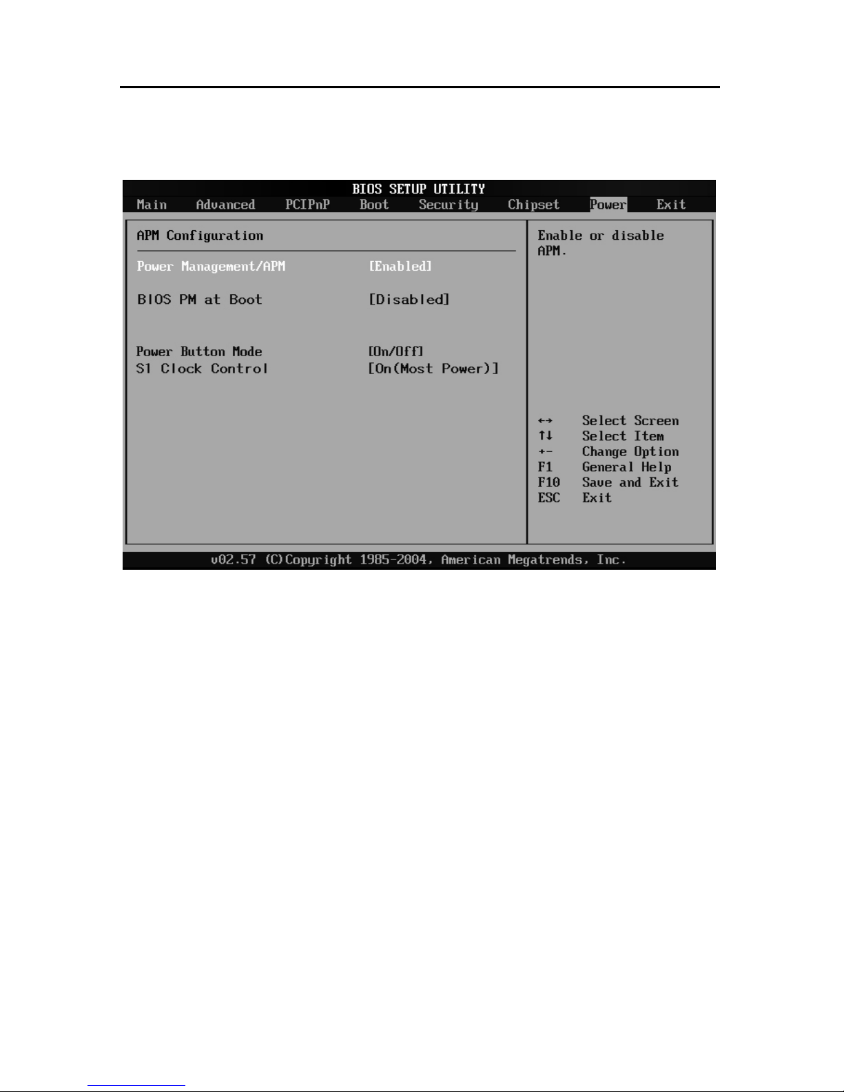
3.9 Power Menu
Power Management/APM
<Enable>: Open power saving mode
<Disable>: Close power saving mode
BIOS PM at POST
<Enable>: Open power saving mode when system executes self-detection
<Disable>: Close power saving mode when system executes self-detection
`
Power Button Mode
<Instant Off>: Press “Power “ button, system will power off
<Suspend>: Press “Power” button, system will be in Standby mode
S1 Clock Control
This option will make the system enter into S1 mode
Page 54
EMB-3682 AMD LX700, support VGA+LVDS or TTL
45
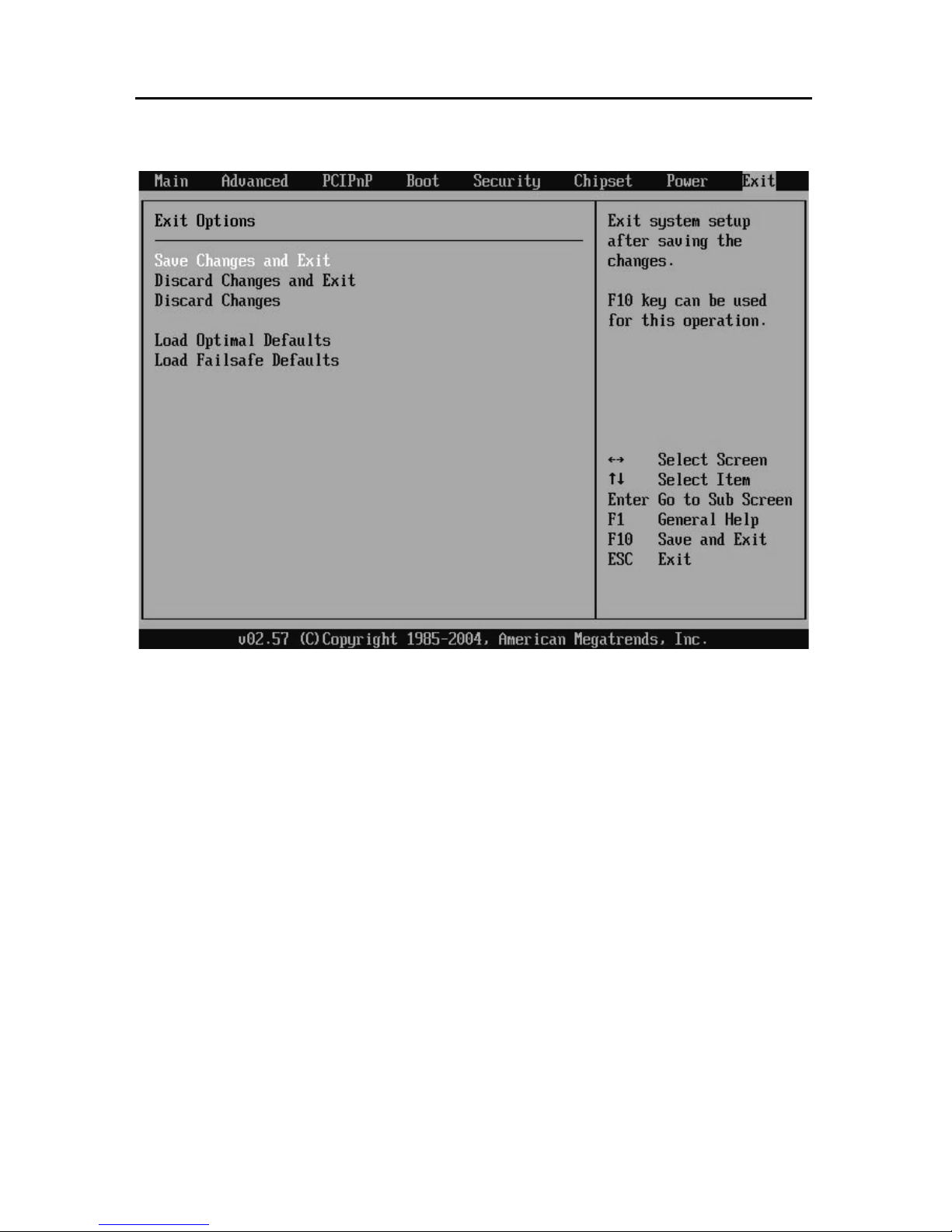
3.10 Exit Menu
Save Changes and Exit
Press <Enter> and <Enter> under this option, to save BIOS changes and exit to
reboot the computer.
Discard Changes and Exit
Press <Enter> and <Enter> under this option to discard BIOS changes and exit.
Discard Changes
Press <Enter> and <Enter> under this option to discard the BIOS changes and stay
at the setup interface.
Load Optimal Defaults
Recommend users to first select this option before config BIOS.
Load Failsafe Defaults
If System fails, recommend to load this option.
Page 55

EMB-3682 AMD LX700, support VGA+LVDS or TTL
46
Chapter 4
Driver Installation
Page 56

EMB-3682 AMD LX700, support VGA+LVDS or TTL
47
Chapter 4 Drivers Installation
4.1 Installation Steps
1.Right click the “My Computer” icon on the desktop, then a menu box will pop
up,please select “ Attributes” and enter into “System Attributes” menu;
2. Select “ Hardware” option and enter into “ Devices Manager”; Double click the
hardware devices marked with yellow”?” or “!” to enter into “Hardware Update Guide”
3. Select “install from the list or the assigned location (advanced)” to go to the next
step, then choose”search the best driver” and check the box beside the options
“ search removable devices” and “ include this in searching”;
4. Click “ view” and locate the position in “Driver\Geode” folder to find the right driver
installation file, then click “next step”
5. To install the driver according to the instructions and then restart the computer;
6. Repeat step 1 to step 5 until all the H/W drivers are installed.
Page 57

Appendix
Page 58

EMB-3862 AMD LX700, support VGA+LVDS or TTL
48
Appendix 1: Glossary
ACPI
Advanced Configuration and Power Management Interface for short. ACPI
specifications allow OS to control most power of computer and its extended devices.
Windows 98/98SE, Windows 2000 and Windows ME are all support ACPI, it provide
users a flexible system power management.
ATX:
AT extended, a motherboard layout complied with modern standard
motherboard layout replacing Baby AT. It changes disposal of many components,
and do some new high efficiency design, so it is widely used now.
BIOS
Basic input/output system. It’s a kind of software including all in/out control
code interface in PC. It will do hardware testing while system is booting, then system
runs, it provides an interface between OS and hardware. BIOS is stored in a ROM
chip.
BUS
In a computer system, it is the channels among different parts for exchanging
data; it’s also a group of hardware lines. BUS here refers to part lines inside CPU
and main components of memory.
Chipset
Integrated chips for executing one or more functions. Here “Chipset” refers to
system level chipset structured by Southbridge & Northbridge; it determines
motherboard’s structure and main functions.
CMOS
Complementary Metal-Oxide Semiconductor, a widely used semiconductor with
the characteristic of high speed but low-power-consumption. CMOS here refers to
Page 59

EMB-3862 AMD LX700, support VGA+LVDS or TTL
49
part of reserved space in on-board CMOS RAM, for saving date, time, system
information and system parameter etc.
COM
Computer-Output Microfilmer. A universal serial communication interface,
usually adopts normative DB9 connector.
DIMM
Dual-Inline-Memory-Module. It’s a small circuit board with memory chipset,
providing 64bit RAM bus width.
DRAM
Dynamic Random Access Memorizer. It’s a normal type of universal memory
often with a transistor and a capacitance to store 1 bit. With the development of the
technology, more and more types of ORAM with various specifications exist in
computer application, such as SDRAM, DDR SDRAM and RDRAM
IDE
Driver specifications for integrated circuit devices, It is widely used for
connecting HDD / CD-ROM devices.
IRDA
Infrared Data Association for short. Here it refers to infrared transmit interface,
to connect infrared transmit devices. This sort of device transmits data by infrared
light-wave without connecting any cables .It has been developed into a standard
now.
LAN
Network interface. Network grouped by correlative computers in a small area,
generally in a company or a building. Local area network is generally buildup by
sever, workstation, some communication links. Terminals can access data and
devices anywhere through cables so that many users can share costly device and
resource.
Page 60

EMB-3862 AMD LX700, support VGA+LVDS or TTL
50
LED
Light-Emitting Diode. a semiconductor device that shines when power supply is
connected, often used to denote info directly by light, for example, to denote power
on or HDD work normally.
LPT
Line print terminal, the denomination reserved by DOS, is an universal parallel
interface usually used to connect printer.
PnP
Plug-and-Play. It is a specification that allows PC to configure its external
devices automatically and can work independently without the manual operation by
its user . To achieve this function, its BIOS should be able to support PnP and a PnP
expansion card.
POST
Self-test when power on. While booting, BIOS will do an uninterrupted testing to
the system, including RAM, keyboard, hard disk driver etc. to check if all the
components are in normal situation and work well.
PS/2
A keyboard & mouse connective interface specification developed by IBM.PS/2
is a DIN interface with only 6PIN; it also can connect other devices, like modem.
USB
It is Universal Serial Bus for short. A hardware interface adapts to low speed
external devices, and is always used to connect keyboard, mouse etc. One PC can
connect maximum 127 USB devices, providing 12Mbit/s transmit bandwidth;USB
supports hot swap and multi- data stream, namely, you can plug USB devices while
system is running, system can auto-detect and makes it work on.
Page 61

EMB-3862 AMD LX700, support VGA+LVDS or TTL
51
Appendix 2:Watchdog Programming Guide
Set the port to realize watchdog function through DEBUG order, so that it can carry
out Watchdog Timer’s various functions.
Port instruction:
2EH :Address register
2FH :Data register
Example:Set Watchdog Timer for 30 Seconds, DEBUG in DOS:
----------------------------------------------------------------C:\>debug
-o 2E 87 ; Decode
-o 2E 87
-o 2E 2b Select watchdog pin
-o 2f C0
-o 2E 07 ; Choose logic devices
-o 2f 08
-o 2E 30 ; Activate logic devices
-o 2f 01
-o 2E F5
-o 2f 00 ; Set timer units as sec /(set as min: o 2f 08)
-o 2E F6
-o 2f 06 ; Set Timer Count to 6 sec. (Max support FF = 255, when it set
as 00 Watchdog function stops)
-o 2E AA
-q
C:\>
Page 62

EMB-3862 AMD LX700, support VGA+LVDS or TTL
52
Packing List
Thank you very much for choosing our products. Please check your package
according to the following item checklist first, if you find any components lost or
damaged, please contact your retailer.
■ EMB-3682 motherboard
■User’s Manual
■Drive & Manual CD-R
■ One Mini IDE
■Three 3x5pin Serial Port convert cable
■One DB9 Serial port convert cable
■One 2x10pin parallel port covert cable
■One 2x4pin USB covert cable
■One PS/2 keyboard&mouse Cable
■Jumpers
Page 63

EMB-3862 AMD LX700, support VGA+LVDS or TTL
53
Announcement
1. Contents of this manual don’t represent the promise of NORCO.
2. Our products are being updated all the time and we are not obliged to inform
you of any modifications in this manual.
3. Our company will not take on the responsibility of any damage or hidden
dangers that may be caused by incorrect configuration or usage.
4. The ownership of all trademarks involved in this manual belong to the
corresponding trademarks holders.
5. For more information about our products, please visit our website:
www.norco-group.com
Page 64

EMB-3862 AMD LX700, support VGA+LVDS or TTL
54
Safety Cautions
1. Please read this manual carefully and keep it well.
2. Please keep the board and cards dry and packed well in storage and transit.
3. Please make sure that power is off before inserting or pulling out extended cards
and other peripherals, especially the memory bank, otherwise, the mainboard and
system memory will be seriously damaged.
4. Please confirm the devices are working under rated power voltage.
5. Please protect your power line and make it not to be trampled or encounter other
suddenness which will cause power off. Don’t place objects on power line.
6. The hatch of chassis is used for ventilation, so please don’t cover or jam such
hatches.
7. Please don’t change or modify this device. If any exceptions occur, please turn to
professionals for help.
8. Please don’t place this device in the environment where temperature is higher
than 60 centigrade, otherwise, the device will be damaged.
Page 65

 Loading...