

Page 1

EMB-3531
V2.2
Page 2

SZ HQ: 0755-27331166
EMB-3531
V2.2
Beijing Office: 010-82671166
Shanghai Office: 021-61212081
Chengdu Office: 028-85259319
Shenyang Office: 024-23960846
Xi’an Office: 029-88338386
Nanjing Office: 025-58015489
Wuhan Office: 027-87858983
Tianjin Office: 022-23727100
Singapore: 65-68530809
For more information, please visit:www.norco.com.cn
Page 3

Disclaimer
Except for the accessories attached to the product as specified herein,
what is contained in this user manual does not represent the commitments
of NORCO Company. NORCO Company reserves the right to revise this
User Manual, without prior notice, and will not be held liable for any direct,
indirect, intended or unintended losses and/or hidden dangers due to
installation or improper operation.
Before ordering products, please learn about the product performance
from the distributors to see if it is in line with your needs. NORCO is a
registered trademark of Shenzhen NORCO Intelligent Technology CO., LTD.
The ownership of other trademarks involved in this manual is owned by its
respective owners.
Page 4

Safety Instructions
1. Please read the product manual carefully before using this product.
2.Put all the unused or uninstalled boards or electronic components in a static dissipative
surface or static shielding bag.
3.Always ground yourself to remove any static discharge before touching the board, to place
your hands on grounding metal object for a while or wear a anti-static wrist strap at all times.
4.When taking or fetching the boards or cards, please wear antistatic gloves and have the
habit of holding the boards by its edges.
5.Make sure that your power supply is set to the correct voltage in your area. Incorrect voltage
may cause personal injuries and damage the system.
6.To prevent electronic shock hazard or any damage to the product, please ensure that all
power cables for the devices are unplugged when adding or removing any devices or
reconfiguring the system.
7.To prevent electrical shock hazard, disconnect the power cable from the electrical outlet
before relocating the system.
8.When adding or removing devices to or from the system, ensure that all the power cables for
the devices are unplugged in advance.
9.To prevent any unnecessary damage to the products due to frequent power on/off, please
wait at least 30 seconds to restart the unit after the shutdown.
10.If system goes wrong during the operation, do not try to fix it by yourself. Contact
a qualified service technician or your retailer.
11.This product is classified as Class A product, which may cause radio interference in our
living environment. On this occasion, users need to take measures to handle the interference.
Page 5

Content
Chapter One Product Introduction
1.1 Hardware Specificattion ...................................................................................................... 1
Chapter Two Hardware Function
2.1 Interface Location and Dimensional Drawing.................................................................... 3
2.2 Installation ..............................................................................................................................3
2.3 Jumper Settings.........................................................................................................................4
2.3.1 COM1 Jumper Settings(J1,J2)
2.3.2 COM2_3 Jumper Settings(J3,J4)
2.3.3 JDOWNLOAD(JD)
2.4 Port Description......................................................................................................................... 6
2.4.1 Serial Ports(COM1,COM2_COM3,COM4_COM7)
2.4.2 USB Ports(USB2_12,USB3_12,USB3_34 ,OTG)
2.4.3 Ethernet Ports(LAN)
2.4.4 Headphone Jack(HEADPHCNE)
2.4.5 Power Amplifier Port(SPEAKER)
2.4.6 Display Ports(HDMI ,LVDS,JLVDS,J11,DP)
2.4.7 Programmable Input and Output Port(GPIO)
2.4.8 Ports(SIM、TF)
2.4.9 Power Port(PWR)
2.4.10 WIFI Port(ANT1)
2.4.11 Front Panel Port(JFP)
2.4.12 MINI PCIe Port...........................................................................................................18
2.4.13 PCIe Port.....................................................................................................................18
2.4.14 CIF_CAMERA and MIPI_CAMERA Port(CIF_CAMERA3, MIPI_CAMERA1-2)
..................................................................................................................................................18
Chapter Three Software Function
3.1 Android 7.1 System.................................................................................................................21
3.1.1 HDMI..............................................................................................................................21
3.1.2 DP...................................................................................................................................21
3.1.3 LCD................................................................................................................................21
3.1.4 USB................................................................................................................................21
..................................................................................................
......................................................................................................
............................................................................
........................................................................
....................................................................................................
.......................................
.......................................
.................................................................................................
.........................................................................
.........................................................................
...........................................
....................................................
.......................................................................................................
...................................................................................................
...................................................................................................
..........................................................................................
...................................................................................................
1
3
5
5
6
6
8
9
10
11
11
14
15
15
16
17
21
Page 6

3.1.5 COM...............................................................................................................................21
3.1.6 CAN................................................................................................................................22
3.1.7 TF Card......................................................................................................................... 22
3.1.8 WIFI................................................................................................................................22
3.1.9 BT...................................................................................................................................22
3.2.0 3/4G............................................................................................................................... 22
3.2.1 Ethernet.........................................................................................................................22
3.2.2 Sound Card...................................................................................................................22
3.2.3 DVP Camera.................................................................................................................23
3.2.4 PCIE Port...................................................................................................................... 22
Appendix
..............................................................................................................................................
Appendix one: Glossary................................................................................................................26
26
Page 7

Packing List
1pcs
Thanks for purchasing NORCO products. Please check the
accessories as per the packing list when you open the package. If you find
any components/parts defected, damaged or lost, please contact your
vendor ASAP.
■ EMB-3531 V2.2 motherboard
Page 8

Chapter
One
Product
Introdu
ction
Page 9

EMB-3531 V2.2
Chapter One
Product Introduction
1.1 Hardware Specification
Size
●Size:146mmX102mm
Processor
●CPU:RK3399 ,hexa-core (dual-core A72 2GHz + quad-core A53 1.5GHz)
System Memory
●On board Memory:on board 2G/4G DDR3
Display
●Provides 1xDP port,supporting resolution: 4Kx2K@60Hz
●Provides 1xLVDS port,supporting resolution: 1920 x1080@60Hz
●Provides 1xHDMI port, supporting resolution: 4Kx2K @60Hz
●Supports independent dual display;
Storage
●Provides1xTF card slot,memory up to 64G
●On board 16G/32G/64G EMMC
AUDIO
●Applies ES8316+NS4258T audio control chip
●Provides one 2X4 connector,support dual-channel power amplifier output and 1xMic-in
●On board power amplifier chip,support 5W dual-channel power amplifier,one on board CTIA
standard headphone jack
LAN
●On board RJ45 Ethernet port,supports 100/1000M network
1
Page 10

EMB-3531 V2.2
I/O
●Serial port:Provides 6x serial port,COM1/3->RS232/RS485/TTL;COM4-7->RS232/TTL
●USB: Provides 7xUSB ports;4xUSB3.0 and 2xUSB2.0,1xOTG port
●Provides: 1xPWM
●Provides: 1xI2C port
Expansion Port:
●1xMINI PCIe slot, supports 3G/4G /WLAN optional
●1xSIM card slot;supports NANO SIM card
●1xPCIEX4 slot,supports PCIE network card
●2xMIPI_CSI port,supports MIPI CAMERA
●1xCIF CAMERA port;
●1x2.00mm 2x6PIN JFP front panel interface
●1x2x15PIN GPIO port,including 12xGPIO(configurable SPI/I2S),1xMIPI_DSI
●Provides: 1x on board WIFI module
Power Supply
●Single supply+12V,supports hardware and software switch for system auto boot upon power
on
Watchdog
●Supports hardware reset function
Operating Environment
●Operating Temperature:0℃~60℃
●Humidity:5%~95%,RH, non-condensing
2
Page 11

Chapter
Two
Hardware
Function
Page 12
EMB-3531 V2.2
3
Chapter Two
Hardware Function
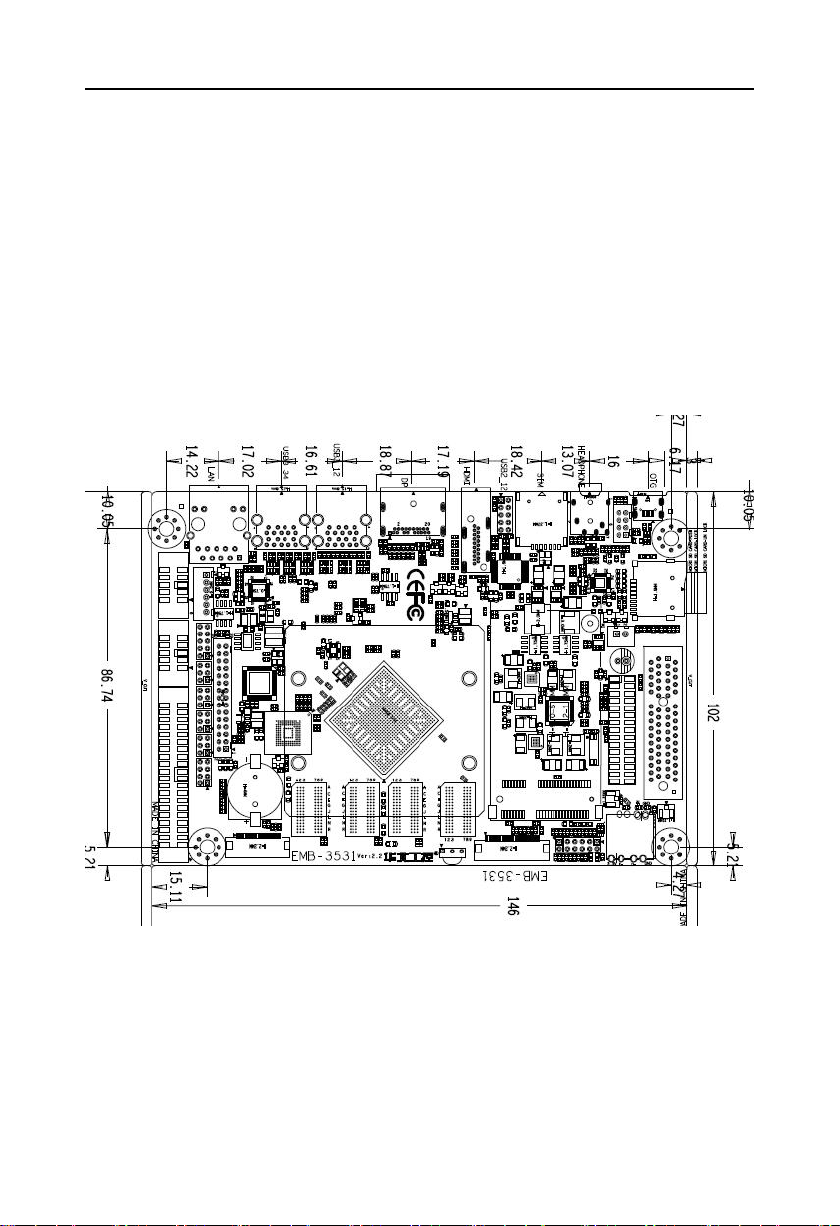
2.1 Interface Location and Dimensional Drawing
Following is the front interface location and dimensional drawing of EMB-3531
V2.2 .Please be careful during the installation. Improper installation may lead to system failure.
Note: In case of any electrostatic damage caused to some components, please wear
anti-static gloves to install the motherboard.
2.2 Installation
Please refer to following steps to assemble your computer:
1.Adjust all jumpers on board EMB-3531 V2.2 according to the user manual.
2.Install other expansion card.
Page 13

EMB-3531 V2.2
4
3.Connect all signal line, cable, ,panel control circuit, and power supplier.
Key components of this motherboard are Integrated circuit and these components
could be easily damaged by electrostatic influence. So, before installing this unit, please
always keep the following precautions in mind:
1.Hold the board by edges and don’t touch any components, plugs or socket pins.
2.Wear anti-static gloves/wrist strap while touching the integrated circuit components, such as
CPU, RAM, etc.
3.Put those unused or uninstalled components in static shielding bags or trays.
4.Please first check the power switch is off before connecting the power plug.
Before installing the computer accessories
Following the instructions below will help to prevent your computer from being
damaged, and also ensuring your personal safety.
1.Please make sure your computer is disconnected from the power supply.
2.Please always wear anti-static strap or gloves to operate the board in case that you
may touch the integrated circuit components, such as RAM.
2.3 Jumper Settings
Please refer to following instructions to do jumper settings before installing your hardware
devices.
Remark: How to identify the PIN1 of all jumpers and interfaces: Please observe the mark near
the plug and socket, which is a “1” or bold line or triangular symbol; And please look at the
back of PCB, the one in the shape of square is the PIN 1; and PIN1 for every jumper is
remarked by a white narrow near it.
Page 14

EMB-3531 V2.2
5
COM1 AS RS232 PORT
COM1 AS RS485 PORT
J1
1-2
J1
3-4 5-6
J2
1-3 2-4
J2
3-5 4-6
J1、J2
J3、J4
2.3.1 COM1 Jumper Settings(J1,J2)
J1、J2:
2.3.2 COM2_3 Jumper Settings(J3,J4)
Page 15

6
J3、J4:
COM3 AS RS232 PORT
COM3 AS RS485 PORT
J3
1-2
J3
3-4 5-6
J4
1-3 2-4
J4
3-5 4-6
JD
1-2
Down load
NC
Default
JD
2.3.3 JDOWNLOAD(JD)
EMB-3531 V2.2
JD:
2.4 Interfaces Description
of any damage to the motherboard!
2.4.1 Serial Ports(COM1,COM2_COM3,COM4_COM7)
6x serial ports , COM1/3 supports RS232/RS485/TTL mode , COM4-7 supports
Please read this manual carefully before installing any external connectors, in case
Page 16

EMB-3531 V2.2
7
Signal Name
Pin
Signal Name
DATA-
12NC
DATA+/RXD
34RTS
TXD
56CTS
NC
78NC
GND
910GND
Signal Name
Pin
Signal Name
DATA-
12DB_RXD
DATA+/RXD
34DB_TXD
TXD
56NC
NC
78NC
GND
910GND
Signal Name
Pin
Signal Name
NC
12NC
COM1
COM2_COM3
COM4_COM7
RS232/TTL mode,COM2 is debugging Port (Not Used as Common Serial Port).
COM1:
COM2_3:
COM4_7:
Page 17

EMB-3531 V2.2
8
RXD
34RTS
TXD
56CTS
NC
78NC
GND
910GND
NC
1112NC
RXD
1314RTS
TXD
1516CTS
NC
1718NC
GND
1920GND
NC
2122NC
RXD
2324RTS
TXD
2526CTS
NC
2728NC
GND
2930GND
NC
3132NC
RXD
3334RTS
TXD
3536CTS
NC
3738NC
GND
3940GND
2.4.2 USB Ports(USB2_12,USB3_12,USB3_34 ,OTG)
Provides 7xUSB ports,in which 4xUSB3.0 and 2xUSB2.0 ports. Provides 1xOTG port.
Page 18

9
USB2_12:
Signal Name
Pin
Signal Name
VCC
12GND
HUB_1-R
34GND
HUB_1+R
56HUB_2+R
GND
78HUB_2-R
GND
910VCC
USB2_12
USB3_12
USB3_34
OTG
EMB-3531 V2.2
2.4.3 Ethernet Port(LAN)
Provides 1xRJ45 Ethernet port ,the yellow one indicates data transmission status, and
the green one indicates network connection status.
Page 19

EMB-3531 V2.2
10
LILED(Green)Status
Function
ACTLED(Yellow)status
Function
ON
100/1000M link
FLASH
Data transmission
OFF
10M link or closed
OFF
Data stopped
LAN
HEADPHCNE
RJ45 LAN LED Status Description:
2.4.4 Headphone Jack(HEADPHCNE)
Provides 1xheadphone jack
Page 20

EMB-3531 V2.2
11
Signal Name
Pin
Signal Name
VCC3
12OUTPL
GND
3
4
OUTNL
MIC+
5
6
OUTNR
MIC-
7
8
OUTPR
SPEAKER
2.4.5 Power Amplifier Interface(SPEAKER)
SPEAKER:
2.4.6 Display Port(HDMI ,LVDS,JLVDS,J11,DP)
Provides 1x HDMI high definition display port,provides 1x LVDS port,provides 1x JLVDS
backlight port, and 1xDP port.
Page 21

12
HDMI:
Signal Name
Pin
Signal Name
D2+
12D2 Shield
D2-
34D1+
D1 Shield
56D1-
D0+
78D0 Shield
D0-
910CK+
CK Shield
1112CK-
CE Remote
1314NC
DDC CLK
1516DDC DATA
GND
1718+5V
HP DET
1920NC
Signal Name
Pin
Signal Name
VDD_PANEL
12VDD_PANEL
VDD_PANEL
3
4
NC
GND
5
6
GND
HDMI
JLVDS
J11
LVDS
DP
EMB-3531 V2.2
LVDS:
Page 22

13
TX0_N
7
8
TX0_P
TX1_N
910TX1_P
TX2_N
1112TX2_P
GND
1314GND
CLK1_N
1516CLK1_P
TX3_N
17
18
TX3_P
TX4_N
19
20
TX4_P
TX5_N
21
22
TX5_P
TX6_N
2324TX6_P
GND
2526GND
CLK2_N
2728CLK2_P
TX7_N
2930TX7_P
J11:
Signal Name
Pin
Signal Name
VCC3
12VCC3
VDD_PANEL
3
4
VDD_PANEL
VCC5
5
6
VCC5
VDD_PANEL
7
8
VDD_PANEL
12VDC_OUT
91012VDC_OUT
Pin
Signal Name
1
GND
2
GND
3
LCD_PWM
4
LCD_EN
EMB-3531 V2.2
JLVDS(LVDS backlight):
Page 23

EMB-3531 V2.2
14
5
12VDC_OUT
6
12VDC_OUT
Signal Name
Pin
Signal Name
3.3V
1
2
3.3V
PWM
3
4
SPI5_RX_33
I2C4_SCL
5
6
SPI5_TX_33
I2C4_SDA
7
8
SPI5_CLK_33
GPIO
910SPI5_CS_33
GND
1112GND
I2S_SDI
1314I2S_SCLK
I2S_SDO
1516I2S_LRCK_RX
I2S_CLK
1718I2S_LRCK_TX
GND
1920GND
MIPI_TX0_D0N
2122MIPI_TX0_D0P
GPIO
2.4.7 Programmable Input and Output Port(GPIO)
GPIO:
Page 24

EMB-3531 V2.2
15
MIPI_TX0_D1N
2324MIPI_TX0_D1P
MIPI_TX0_CLKN
2526MIPI_TX0_CLKP
MIPI_TX0_D2N
2728MIPI_TX0_D2P
MIPI_TX0_D3N
2930MIPI_TX0_D3P
SIM card slot
TF card port
2.4.8 Ports(SIM、TF)
Provides 1x SIM card slot and TF card port.
2.4.9 Power Port(PWR)
Provides one green European power socket and one 1x2 Pin connector.
Page 25

16
PWR:
Pin
Signal Name
1
+12V
2
GND
PWR
ANT1
EMB-3531 V2.2
2.4.10 WIFI port(ANT1)
Provide 1x WIFI port.
Page 26

EMB-3531 V2.2
17
Signal Name
Pin
Signal Name
PWR_LED
12GND
ADC0
34ADC3
ADC2
56ADC4
RESET
78GND
PWRSW
910GND
DOWN LOAD
RESET
PWRSW
JFP
2.4.11 Front Panel Port(JFP)
JFP connects power button and indicator on the front panel.
JFP:
Please connect following chart below, and pay attention to the anode (+) and cathode (-). If it is
falsely connected, it may not function well.
2)Reset Button Pins(Pin7, Pin8 for RESET BUTTON)
Connect the reset button cable to these two pins. When system fails, the reset button will
restart the system to back to work so there is no need to turn on / off power. It can extend the
Page 27

EMB-3531 V2.2
18
CIF_CAMERA 3
MIPI_CAMERA 1
service life of the system.
3)Power ON/OFF Pins(Pin9, Pin10 POWER BUTTON)
Connect these two pins to the bounce switch on the chassis to connect or disconnect the power
Supply
.
2.4.12 MINI PCIe Port
Provides 1xMINI PCIe slot,you are able to expand MINI PCIe device according to your
requirement, like 3G/4G module.
2.4.13 PCIe Port
Provides 1xPCIe port,you are able to expand PCIe device according to your requirement.
2.4.14 CIF_CAMERA and MIPI_CAMERA Port (CIF_CAMERA3,MIPI_CAMERA1-2)
Page 28

19
MIPI_CAMERA1:
Signal Name
Pin
Signal Name
GND
12RX1_D0N
RX1_D0P
34GND
RX1_CLKN
56RX1_CLKP
GND
78RX1_D1N
RX1_D1P
910GND
RX1_D2N
1112RX1_D2P
GND
1314RX1_D3N
RX1_D3P
1516GND
MCLK1
1718GND
PWDN
1920RESET
SCL_MIPICM2
2122SDA_MIPICM2
GND
2324VCC_2V8_CAM
GND
2526NC
VCCA1V8_CAM
2728VCC_1V2_CAM
VCC_2V8_CAM
2930NC
Signal Name
Pin
Signal Name
GND
12RX0_D0P
RX0_D0N
34GND
RX0_CLKN
56RX0_CLKP
MIPI_CAMERA 2
EMB-3531 V2.2
MIPI_CAMERA2:
Page 29

20
GND
78RX0_D1N
RX0_D1P
910GND
RX0_D2N
1112RX0_D2P
GND
1314RX0_D3N
RX0_D3P
1516GND
MIPI_MICLK0
1718GND
PWDN
1920RESET
SCL_MIPICM1
2122SDA_MIPICM1
GND
2324VCC_2V8_CAM
GND
2526NC
VCCA1V8_CAM
2728VCC_1V8_CAM
VCC_2V8_CAM
2930NC
CIF_CAMERA3:
Signal Name
Pin
Signal Name
NC
12NC
CIF_D2
34CIF_D1
CIF_D3
56CIF_D0
CIF_D4
78CIF_CLKI
CIF_D5
910GND
CIF_D6
1112CIF_MCLK
CIF_D7
1314VCCA1V8_CAM
VCCA1V8_CAM
1516CIF_HREF
DVP_PDN0_H
1718CIF_VSYNC
GPIO0_B3
1920SCL_CIF
VCC_2V8_CAM
2122SDA_CIF
GND
2324GPIO_B2
EMB-3531 V2.2
Page 30

Chapter
Three
Software
Function
Page 31

EMB-3531 V2.2
21
Chapter Three
Software Function
3.1 Android 7.1 System
3.1.1 HDMI
Supports HDMI output
Instruction: Use HDMI cable to connect motherboard and display, and you can see Android
interface when you turn on computer.
3.1.2 DP
Supports DP output
Instruction: Use DP cable to connect motherboard and display, and you can see Android
interface when you turn on computer.
3.1.3 LCD
Supports lvds lcd port output
Drivers need to be customized according to the actual use of LCD screen.
3.1.4 USB
Support 4xUSB3.0 2xUSB2.0(Pin)
Instruction: connect USB flash disk to USB port, and check USB flash disk device:
/mnt/media_rw/.
3.1.5 COM
Support 6xserial port
Device node:CPU self contained: /dev/ttyS0~/dev/ttyS1, expanding: ttyVIZ0-ttyVIZ3
Instructions: Install ComAssistant program, short circuit rx, tx. Select the device node above
and click Send. It will be regarded as normal if the data sent by the sender can be seen in the
receiving area. (Note that there are many serial ports, short circuit rx tx should be
correspondence accordingly)
Page 32

EMB-3531 V2.2
22
3.1.6 CAN
Nonsupport
3.1.7 TF card
Support
Instruction: Insert TF card into USB port, and check USB flash disk device: /mnt/media_rw/
3.1.8 WIFI
Support,See the Android interface for details
Instruction: In the system open setting-> Wireless & networks-> Wi-Fi, turn on Wi-Fi, and you
can see wireless router SSID on the right, connect one of them, and input router password if
needed. Enter a password if the router has a password.
3.1.9 BT
Support
Default motherboard does not support BT. If BT is to be supported, the WiFi + BT module
should be replaced with the sales communication. The software needs no modification and is
compatible.
3.2.0 3/4G
Support
Customize drive according to 3/4G module customer used.
3.2.1 Ethernet
Support,See Android interface for specific operation
Instructions for use: Open the network cable under the system - > more - > Ethernet, select
HDCP or Static IP according to actual needs.
3.2.2 Sound Card
Support,Local sound card output, HDMI sound output
Instructions:
The default sound is output from the local power amplifier. If HDMI port is needed to output
Page 33

EMB-3531 V2.2
23
sound, the system needs to be re-customized.
3.2.3 DVP Camera
Support,
Customized Driver for DVP Camera Model Based on Customer's Actual Use
3.2.4 PCIE Port
Support
Drivers should be customized according to the actual use of PCIe equipment by customers.
Page 34

Appendix
Page 35

EMB-3531 V2.2
26
Appendix
Appendix 1: Glassory
ACPI
Advanced Configuration and Power Management. ACPI specifications allow operating
system to control most power of the computer and its add-ons. Windows 98/98SE,Windows
2000 and Windows ME supports this specification.
BIOS
Basic input/output system. It is software including all in/out control code interface in PC.
The software will detect hardware when it auto boot, operate OS, and provide an interface
between OS and hardware. BIOS is stored in a ROM chip.
BUS
BUS is a channel for different devices to exchange data in computer system. It is hardware
circuit. BUS here refers to partial lines inside CPU and the main components of system
memory.
Chipset
Chipset is a Integrated set of chips for executing one or more related functions。Here it
refers to a system level chipset structured by Southbridge & Northbridge; Chipset decides the
structure and main functions of motherboard.
CMOS
Complementary Metal-Oxide Semiconductor, which is a widely used semiconductor with
the characteristics of high-speed and low-power. COMS here refer to part of space on-board
CMOS RAM for saving date, time, system information and system parameter, ect.
COM
Cluster Communication Port. A universal serial communication interface, usually adopts
Page 36

EMB-3531 V2.2
27
normative DB 9 connector.
DIMM
Dual-Inline-Memory-Modules. It is a small circuit board with memory chipset providing 64
bit memory bus width.
DRAM
Dynamic Random Access Memory. It is a general type of memory for regular computer
which usually store 1 bit with a transistor and a capacitance. With the development of the
technology, more and more types of DRAM with different specifications exist in computer
applications. For example: SDRAM/DDR SDRAM/RDRAM
LAN
Local Area Network. Network grouped by correlative computers in a small area, generally
in a company or a building. Local area network is buildup by sever, workstation, some
communications links. Terminals can access data and devices anywhere through cables,
which enables users to share costly devices and resource.
LED
Light-Emitting Diode. A semiconductor device that lighted when power supply is connected,
It is often used to indicate information directly, for example, to indicate power on or HDD
working normally.
PnP
Plug-and-Play. It is a specification that allows PC to configure its external devices
automatically and it works independently without the manual operation. To achieve this function,
BIOS should be able to support PnP and a PnP expansion card
POST
Power On Self Test. While the system is booting, BIOS will keep testing the system which
including RAM, keyboard, hard disk driver to check if all the components are connected directly
and function well.
Page 37

EMB-3531 V2.2
28
PS/2
A keyboard & mouse connective interface specification developed by IBM.PS/2 is a DIN
interface with only 6PIN; it also can connect other devices, like modem
USB
It is the Universal Serial Bus for short. A hardware interface adapts to low speed
peripherals, and is always used to connect keyboard, mouse etc. One PC can connect
maximum 127 USB devices, providing 12Mbit/s transmit bandwidth USB supports hot swap
and multi- data stream, namely, you can plug USB devices while system is running, system can
auto-detect and makes it work on.
Page 38

 Loading...