

Page 1

EMB-3501
USER' Manual V1.0
Page 2

EMB-3501
USER' Manual V1.0
SZ HQ: 0755-27331166
Beijing Office: 010-82671166
Shanghai Office: 021-61212081
Chengdu Office: 028-85259319
Shenyang Office: 024-23960846
Xi’an Office: 029-88338386
Nanjing Office: 025-58015489
Wuhan Office: 027-87858983
Tianjin Office: 022-23727100
Singapore: 65-68530809
Netherland: 31-040-2668554
For more information, please visit:www.norco.com.cn
Page 3

Disclaimer
Except for the accessories attached to the product as specified herein, what is contained in
this user manual does not represent the commitments of NORCO Company. NORCO
Company reserves the right to revise this User Manual, without prior notice, and will not be held
liable for any direct, indirect, intended or unintended losses and/or hidden dangers due to
installation or improper operation.
Before ordering products, please learn about the product performance from the distributors
to see if it is in line with your needs. NORCO is a registered trademark of Shenzhen NORCO
Intelligent Technology CO., LTD. The ownership of other trademarks involved in this manual is
owned by its respective owners.
The contents of this manual are protected by copyright law. All rights are strictly reserved.
Any form of unauthorized reproduction including but not limited to carbon copy, facsimile
transmission and electronic copy or email is prohibited.
Page 4

Safety Instructions
1. Please read the product manual carefully before using this product.
2.Put all the unused or uninstalled boards or electronic components in a static dissipative
surface or static shielding bag.
3.Always ground yourself to remove any static discharge before touching the board, to place
your hands on grounding metal object for a while or wear a anti-static wrist strap at all times.
4.When taking or fetching the boards or cards, please wear antistatic gloves and have the
habit of holding the boards by its edges.
5.Make sure that your power supply is set to the correct voltage in your area. Incorrect voltage
may cause personal injuries and damage the system.
6.To prevent electronic shock hazard or any damage to the product, please ensure that all
power cables for the devices are unplugged when adding or removing any devices or
reconfiguring the system.
7.To prevent electrical shock hazard, disconnect the power cable from the electrical outlet
before relocating the system.
8.When adding or removing devices to or from the system, ensure that all the power cables for
the devices are unplugged in advance.
9.To prevent any unnecessary damage to the products due to frequent power on/off, please
wait at least 30 seconds to restart the unit after the shutdown.
10.If system goes wrong during the operation, do not try to fix it by yourself. Contact
a qualified service technician or your retailer.
11.This product is classified as Class A product, which may cause radio interference in our
living environment. On this occasion, users need to take measures to handle the interference.
Page 5

Content
Chapter One Product Introduction ................................................. 1
1.1 Hardware Specification ............................................................................................. 1
Chapter Two Hardware Function .................................................... 3
2.1 interface location and dimensional drawing .............................................................. 3
2.2 Installation ................................................................................................................ 3
2.3 Jumper Settings ....................................................................................................... 4
2.3.1 COM2 Jumper settings(J1、J2、J3) ........................................................ 4
2.3.2 Jumper(JDOWNL OAD) ........................................................................... 5
2.3.3 Jumper(J11)............................................................................................. 6
2.4 Poprt Describtion ...................................................................................................... 6
2.4.1 Serial Ports(COM1_DB、COM2_COM5) ................................................. 6
2.4.2 SATA Ports(SATA1、SATA2) ................................................................... 8
2.4.3 SATA Power Interface(SATA_PWR1、SATA_PWR2) .............................. 9
2.4.4 USB Ports(USB12、USB34、USB5) ...................................................... 9
2.4.5 Ethernet Port(LAN) ................................................................................ 11
2.4.6 Audio Port(AUDIO) ................................................................................ 11
2.4.7 JGPIO ........................................................................................................ 13
2.4.7 Display Interface(VGA, LVDS,k HDMI, LVDS power interface J11, LVDS
backlight control pot JLVDS) ............................................................................. 13
2.4.8 (JTCH) .................................................................................................. 17
2.4.9 Power Port(PWRIN) ............................................................................... 18
2.4.10 Ports(TP) ............................................................................................. 18
2.4.11 Ports(OTG、TF、SIM) ......................................................................... 19
2.4.12 Front Panel Port(JFP) .......................................................................... 19
2.4.13 MINI PCIe Port ................................ ......................................................... 21
Chapter Three Software Function ................................................. 22
3.1 Android System ...................................................................................................... 22
3.1.1VGA Part ..................................................................................................... 22
3.1.2 HDMI Part .................................................................................................. 22
Page 6

3.1.3 LCD Part .................................................................................................... 22
3.1.4 USB Part .................................................................................................... 22
3.1.5 COM Part ................................................................ ................................ ... 22
3.1.6 TF Card Part .............................................................................................. 23
3.1.7 SATA Hardware Part ................................................................................... 23
3.1.8 WIFI Part .................................................................................................... 23
3.1.9 3G Part....................................................................................................... 23
3.1.10 Ethernet Part ............................................................................................ 23
3.1.11 Sound Card Part ....................................................................................... 23
3.2Linux System ........................................................................................................... 24
3.2.1VGA Part ..................................................................................................... 24
3.2.2 HDMI Part .................................................................................................. 24
3.2.3 LCD Part .................................................................................................... 24
3.2.4 USB Part .................................................................................................... 24
3.2.5 COM Part ................................................................ ................................ ... 24
3.2.6 TF Card Part .............................................................................................. 25
3.2.7 SAT Hardware Part..................................................................................... 25
3.2.8 WIFI Part .................................................................................................... 25
3.2.9 3G Part....................................................................................................... 25
3.2.10 Ethernet Part ............................................................................................ 25
3.2.11 Sound Card Part ....................................................................................... 26
Appendix ....................................................................... 27
Appendix one Glossary ................................................................................................ 27
Page 7

1 pcs
Packing List
Thanks for purchasing NORCO products. Please check the accessories as per the
packing list when you open the package. If you find any components/parts
defected, damaged or lost, please contact your vendor ASAP.
■ EMB-3501 V1.0 motherboard
Page 8

Chapter One
Product Introduction
Page 9

EMB-3501 V1.0 Freescale i.MX6 Platform Motherboard
Chapter One Product Introduction
1.1 Hardware Specification
Size
●Size:146mmX102mm
Processor
●CPU:IMX6Q/DL/S
System Memory
●Onboard Memory: default 1GB, supports DDRⅢ 800
Display
●Display Port:VGA,LVDS,HDMI
●VGA: 1x VGA port
●LVDS: 1x dual channel LVDS 2.0mm pin, supports 24Bit 1920×1080@60Hz
●HDMI: i.MX6 series integrated CPU, supports maximum resolution: 1920x1080@60Hz
Ethernet
●network controller: RJ45(10/100/1000Mbps) X 1
Storage
●Supports 2x standard 7Pin SATA port
●SD: supports Micro SD
●FLASH: onboard 8GB INAND
AUDIO
●Applies SGTL5000 audio control chip
●Provides 1x MIC-in pin, 1x Line-in pin, 1x Line-out pin
●Onboard power amplifier supports 2x 5W 2Ohm speaker
1
Page 10

EMB-3501 V1.0 Freescale i.MX6 Platform Motherboard
I/O
●Serial Ports: Provides 5x serial port, COM2 supports RS232/RS422/RS485; COM1,
COM3-COM5 support RS232
●USB: Provides 7x USB 2.0 port, 1x standard dual USB2.0 port, 1x 2x5 2.0mm USB2.0 pin, 1x
1x5 2.0mm connector, 1x onboard USB wifi, 1x miniPCIE USB2.0 port
Expansion Port
●1x MINI PCIe, supports WiFi、3G module
●Onboard SIM card socket, supports 3G network, and it works with MINI PCIe 3G module
●Supports 18x GPIO port
Power Support
●+12V single power supply
Watchdog
●Supports hardware reset function
Operating Environment
●Operating temperature: -20~+65℃
●Storage temperature: -40~+85℃
●Operating humidity: 5%~95%, non-condensing
●Storage humidity: 5%~95%, non-condensing
2
Page 11

Chapter Two
Hardware Functions
Page 12
3
EMB-3501 V1.0 Freescale i.MX6 Platform Motherboard
Chapter Two Hardware Functions
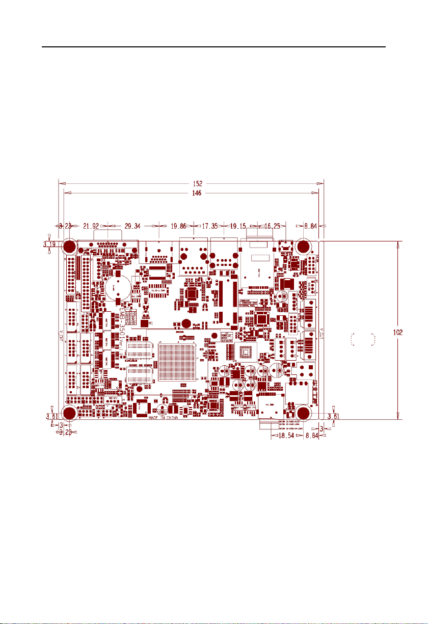
2.1 interface location and dimensional drawing
Following is the front interface location and dimensional drawing of EMB-3501 V1.0.
Please be careful during the installation. Improper installation may lead to system failure.
Note: In case of any electrostatic damage caused to some components, please wear
anti-static gloves to install the motherboard.
2.2 Installation
Please refer to following steps to assemble your computer:
1.Adjust all jumpers on board EMB-3501 V1.0 according to the user manual
2.Install other expansion card
3.Connect all signal lines, cables, control panel circuit and power supply unit
Page 13

4
EMB-3501 V1.0 Freescale i.MX6 Platform Motherboard
Key components of this motherboard are Integrated circuit and these components
could be easily damaged by electrostatic influence. So, before installing this unit, please
always keep the following precautions in mind:
1.Hold the board by edges and don’t touch any components, plugs or socket pins.
2.Wear anti-static gloves/wrist strap while touching the integrated circuit components, such as
CPU, RAM, etc.
3.Put those unused or uninstalled components in static shielding bags or trays.
4.Please first check the power switch is off before connecting the power plug.
Before installing the computer accessories
Following the instructions below will help to prevent your computer from being damaged, and
also ensuring your personal safety.
1.Please make sure your computer is disconnected from the power supply.
2.Please always wear anti-static strap or gloves to operate the board in case that you may
touch the integrated circuit components, such as RAM.
2.3 Jumper Settings
Please refer to following instructions to do jumper settings before installing your hardware
devices.
Remark: How to identify the PIN1 of all jumpers and interfaces: Please observe the mark near
the plug and socket, which is a “1” or bold line or triangular symbol; And please look at the back
of PCB, the one in the shape of square is the PIN 1; and PIN1 for every jumper is remarked by
a white narrow near it.
2.3.1 COM2 Jumper Settings(J1、J2、J3)
(J1 , J2,J3) jumpers are used to set COM2 transmission mode, COM2 supports
RS232/RS422/RS485 three modes, and you can set it according to your requirement, while the
default setting is RS232.
Page 14

5
COM2 AS RS232 PORT
COM2 AS RS422 PORT
COM2 AS RS485 PORT
J1
1-3,2-4
J1
3-5,4-6
J1
3-5,4-6
J2
1-3,2-4
J2
3-5,4-6
J2
3-5,4-6
J3
1-2
J3
3-4
J3
5-6,7-8
J3
J1、J2
JDOWNLOAD
EMB-3501 V1.0 Freescale i.MX6 Platform Motherboard
J1、J2、J3:
2.3.2 Jumper(JDOWNL OAD)
JDOWNLOAD:
Page 15

6
Mode
1-2
DOWNLOAD(System Recording Mode)
NC
NORMAL(Normal Start Mode)
Mode
1-3,2-4
LVDS power supply 3.3V
3-5,4-6
LVDS power supply 5V
7-9,8-10
LVDS power supply 12V
J11
EMB-3501 V1.0 Freescale i.MX6 Platform Motherboard
2.3.3 Jumper(J11)
J11:
2.4 Interfaces Description
Please read this manual carefully before installing any external connectors, in case
of any damage to the motherboard!
2.4.1 Serial Ports(COM1_DB、COM2_COM5)
Provides 5x serial port, and COM 2 supports RS232/RS422/ RS485 modes. COM1,
Page 16

7
Signal Name
Pin
Signal Name
NC
1 2 NC
RXD
3 4 RTS
TXD
5 6 CTS
NC
7 8 NC
GND
9
10
GND
Signal Name
Pin
Signal Name
NC
1 2 NC
RXD
3 4 RTS
TXD
5 6 CTS
NC
7 8 NC
GND
9
10
GND
COM1_DB
COM2-COM5
EMB-3501 V1.0 Freescale i.MX6 Platform Motherboard
COM3_COM5 support RS232 mode.
COM_DB:
COM2_COM5:
Page 17

8
Pin
RS232(default)
RS422
RS485 1 NC
TX-
DATA- 2 NC
NC
NC
3
COM_RXD
TX+
DATA+
4
COM_RTS#
NC
NC
5
COM_TXD
RX+
NC
6
COM_CTS#
NC
NC 7 NC
RX-
NC 8 NC
NC
NC 9 GND
GND
GND
10
GND
GND
GND
Pin
Signal Name
1
GND 2 TX+
SATA1、SATA2
EMB-3501 V1.0 Freescale i.MX6 Platform Motherboard
When COM2 setting is RS232/RS422/RS485, the pins are defined as:
2.4.2 SATA Ports(SATA1、SATA2)
Provides 2x standard 7Pin SATA port.
SATA:
Page 18

9
3
TX- 4 GND 5 RX- 6 RX+ 7 GND
Pin
Signal Name
1
+3.3V
2
GND 3 +5V 4 GND
SATA_PWR1
SATA_PWR2
EMB-3501 V1.0 Freescale i.MX6 Platform Motherboard
2.4.3 SATA Power Port(SATA_PWR1、SATA_PWR2)
SATA_PWR1、SATA_PWR2:
2.4.4 USB Port (USB12、USB34、USB5)
Provides 5x USB 2.0 port, 2x standard USB2.0 port, 3x USB2.0mm pin.
Page 19

10
Pin
Signal Name
1、2
+5V
3、4
DATA-
5、6
DATA+
7、8
GND
Signal Name
Pin
Signal Name
+5V
1 2 GND
DATA-
3 4 GND
DATA+
5 6 DATA+
GND
7 8 DATA-
GND
9
10
+5V
Pin
Signal Name
1
+5V
2
DATA-
3
DATA+
4
GND
5
GND
USB12
USB34
USB5
EMB-3501 V1.0 Freescale i.MX6 Platform Motherboard
USB12:
USB34:
USB5:
Page 20

11
LILED(Green) Status
Function
ACTLED(Yellow)
Function
ON
100/1000M link
Flash
Data transferring
OFF
10M link or closed
Off
Data stopped
LAN
EMB-3501 V1.0 Freescale i.MX6 Platform Motherboard
2.4.5 Ethernet Port(LAN)
Provides 1x RJ45 Ethernet port, and yellow is on data transmission, and green is network
connected.
RJ45 LAN LED Status Description
2.4.6 Audio Port(AUDIO,SPEAKER)
EMB-3501 V1.0 applies SGTL5000-XNAA3 audio control chip.
Page 21

12
Signal Name
Pin
Signal Name
GND
1 2 MIC1
LIN_L
3 4 LIN_R
GND
5 6 GND
NC
7 8 HeadPh_R
NC
9
10
HeadPh_L
Pin
Signal Name
1
OUTPL
2
OUTNL
3
OUTNR
4
OUTPR
AUDIO
SPEAKER
EMB-3501 V1.0 Freescale i.MX6 Platform Motherboard
AUDIO:
SPEAKER:
Page 22

13
Signal Name
Pin
Signal Name
GND
1 2 3.3V
GPIO1
3 4 GPIO18
GPIO2
5 6 GPIO17
GPIO3
7 8 GPIO16
GPIO4
9
10
GPIO15
GPIO5
11
12
GPIO14
GPIO6
13
14
GPIO13
GPIO7
15
16
GPIO12
GPIO8
17
18
GPIO11
GPIO9
19
20
GPIO10
JGPIO
EMB-3501 V1.0 Freescale i.MX6 Platform Motherboard
2.4.7 JGPIO
JGPIO:
2.4.7 Display Port (VGA、LVDS、HDMI、LVDS power port J11、LVDS backlight
control port JLVDS)
Provides 1x VGA port, 1x dual channel LVDS port, 1 HDMI high definition display port.
Page 23

14
Pin
Signal Name
Pin
Signal Name
Pin
Signal Name
1
RED 6 GND
11
NC
HDMI
LVDS
VGA
J11
JLVDS
EMB-3501 V1.0 Freescale i.MX6 Platform Motherboard
VGA:
Page 24

15
2
GREEN
7
GND
12
SDA
3
BLUE
8
GND
13
HSYNC
4
NC 9 +5V
14
VSYNC
5
GND
10
GND
15
SCL
Signal Name
Pin
Signal Name
VDD
1 2 VDD
VDD
3 4 NC
GND
5 6 GND
LVDS0_TX0_N
7 8 LVDS0_TX0_P
LVDS0_TX1_N
9
10
LVDS0_TX1_P
LVDS0_TX2_N
11
12
LVDS0_TX2_P
GND
13
14
GND
LVDS0_CLK_N
15
16
LVDS0_CLK_P
LVDS0_TX3_N
17
18
LVDS0_TX3_P
LVDS1_TX0_N
19
20
LVDS1_TX0_P
LVDS1_TX1_N
21
22
LVDS1_TX1_P
LVDS1_TX2_N
23
24
LVDS1_TX2_P
GND
25
26
GND
LVDS1_CLK_N
27
28
LVDS1_CLK_P
LVDS1_TX3_N
29
30
LVDS1_TX3_P
Signal Name
Pin
Signal Name
D2+
1
2 D2 Shield
D2-
3
4 D1+
D1 Shield
5
6 D1- D0+
7
8 D0 Shield
D0-
9
10 CK+
CK Shield
11
12 CK-
CE Remote
13
14 NC
DDC CLK
15
16
DDC DATA
GND
17
18
+5V
EMB-3501 V1.0 Freescale i.MX6 Platform Motherboard
LVDS:
HDMI:
Page 25

16
HP DET
19
20 NC
Signal Name
Pin
Signal Name
+3.3V
1 2 +3.3V
VDD
3 4 VDD
+5V
5 6 +5V
VDD
7 8 VDD
+12V
9
10
+12V
Pin
Signal Name
1
+12V
2
+12V
3
LCD_EN
4
LCD_PWM
5
GND
6
GND
EMB-3501 V1.0 Freescale i.MX6 Platform Motherboard
LVDS power supply port J11:
JLVDS (Backlight power and control):
Page 26

17
Signal Name
Pin
Signal Name
+3.3V
1 2 GND
LVDS1_SCL
3 4 LVDS0_SCL
LVDS1_SDA
5 6 LVDS0_SDA
EIM_CS1
7 8 EIM_D23
JTCH
EMB-3501 V1.0 Freescale i.MX6 Platform Motherboard
2.4.8 (JTCH)
JTCH:
Page 27

18
Pin
Signal Name
1
GND
2
GND
3
+12V
4
+12V
TP
PWRIN
EMB-3501 V1.0 Freescale i.MX6 Platform Motherboard
2.4.9 Power Port(PWRIN)
PWRIN:
2.4.10 Ports(TP)
Page 28

19
Pin
Signal Name
1
X+
2
Y+
3
X- 4 Y-
OTG
TF
SIM
EMB-3501 V1.0 Freescale i.MX6 Platform Motherboard
TP:
2.4.11 Ports (OTG、TF、SIM)
Provides 1x standard OTG port and 1x TF card port, 1x SIM card port
2.4.12 Front Panel Port(JFP)
JFP is used to connect power button and indicator on the front panel
Page 29

20
Signal Name
Pin
Signal Name
LED+
1 2 LED-
RST+
3 4 RST-
PWRSW+
5 6 PWRSW-
POWER LED
RESET SW
PWR SW
JFP
EMB-3501 V1.0 Freescale i.MX6 Platform Motherboard
JFP:
Please connect following chart below, and pay attention to the anode (+) and cathode (-). If it is
falsely connected, it may not function well.
1) System power LED pins (pin1, pin2 for PWLED)
Connect system power LED cable with these pins.(pin 1 is LED anode)When system is power
on, power LED is on;when system is power off, power LED is off.
2)Reset Button Pins(Pin 3, Pin4 for RESET BUTTON)
Connect the reset button cable to these two pins. When system fails, the reset button will
restart the system to back to work so there is no need to turn on / off power.
Page 30

21
EMB-3501 V1.0 Freescale i.MX6 Platform Motherboard
3)Power ON/OFF Pins(Pin 5, Pin6 for POWER BUTTON)
Connect these two pins to the bounce switch on the chassis to connect or disconnect the power
supply.
2.4.13 MINI PCIe Port
Provides 1x MINI PCIe slot, you are able to expand MINI PCIe device according to your
requirement and status of WLAN card will be displayed according to the network when you use
PCIe WLAN card.
Page 31

Chapter Three
Software Functions
Page 32

EMB-3501 V1.0 Freescale i.MX6 Platform Motherboard
Chapter Three Software Functions
3.1 Android System
3.1.1VGA Part
Supports vga output
Instruction: System supports VGA+HDMI dual-screen display, Connect the board to display
with a VGA cable, and you can see Android display when you turn on the computer.
3.1.2 HDMI Part
Support HDMI output
Instruction: System supports VGA+HDMI dual-screen display. Connect the board to display
with a HDMI cable, and you can see Android display when you turn on the computer.
3.1.3 LCD Part
Support lvds lcd port output, and customize drive according to LCD screen customer used.
3.1.4 USB Part
USB flash disk auto mounted directory: /mnt/udisk/
Instruction: Insert USB flash disk in to USB port, and open file browser to go to /mnt/udisk
directory then you can check files in USB flash disk
3.1.5 COM Part
Serial port operation node: /dev/ttymxc0~/dev/ttymxc4
Instruction:
Connect serial port 2~5 to the circuit
busybox cp -rf com_arm/ /data/
cd /data/com_arm/
input ./c_android.sh
Input Baud rate and testing time
Display testing result after the program stops running
22
Page 33

EMB-3501 V1.0 Freescale i.MX6 Platform Motherboard
3.1.6 TF Card Part
Tf card auto mounted directory:/dev/extsd/
Instruction: Insert TF card into TF port, and open file browser to enter /mnt/extsd directory and
then you can check files in TF card.
3.1.7 SATA Hardware Part
Customize mounted directory according to customer requirement, and supports 2x SATA auto
mount as default setting
Instruction: Connect SATA hard disk to board SATA port when computer is power on, and open
file browser to enter /mnt/satadisk1 or /mnt/satadisk2 directory then you can check files in SATA
hard disk.
3.1.8 WIFI Part
Supported, specific operation refers to android interface
Instruction: In the system open setting-> Wireless & networks-> Wi-Fi, turn on Wi-Fi, and you
can see wireless router SSID on the right, connect one of them, and input router password if
needed.
3.1.9 3G Part
Customize drive according to the 3G module customers used, compatible with: HUAWEI
MU609, MU709, MC509, ZTE MC2716 and Long UNG U8300C.
3.1.10 Ethernet Part
Supported, specific operation refers to android interface
Instruction: In the system open setting-> Wireless & networks-> Ethernet configuration, check
Ethernet, and click on Ethernet configuration, for Ethernet Devices, select etho for first WLAN
card and select eth1 for second WLAN card, select HDCP or Static IP as Connection Type
according to your requirement.
3.1.11 Sound Card Part
Supported, local sound card outputs android to switch
Instruction: HDMI plays audio or video files. Test sound output with earphone and other
sound equipments.
23
Page 34

EMB-3501 V1.0 Freescale i.MX6 Platform Motherboard
Local sound card: alsa_aplay xx.wav
3.2Linux System
3.2.1VGA Part
Supported
Instruction: system supports VGA+HDMI dual-screen display by default. Connect motherboard
to display with a VGA cable, and you can see Linux interface when you turn on computer.
3.2.2 HDMI Part
Supports HDMI output
Instruction: Supports VGA+HDMI dual-screen display by default. Connect motherboard to
display with HDMI cable, and you can see Linux display when you turn on compueter.
3.2.3 LCD Part
Supports lvds lcd port output, and customize LCD screen according to customer requirement.
3.2.4 USB Part
Supported
Instruction: Insert USB flash disk to USB port, and check USB flash disk device: fdisk –l
Mount the USB flash disk under the system: mount /dev/sdX1 /mnt (sdX1 is the device name
of the USB flash disk)
Enter USB flash disk directory to operate files in USB flash disk: cd /mnt
3.2.5 COM Part
Device node: /dev/ttymxc0~/dev/ttymxc4
Instruction: Connect serial port 2~5 to the circuit
busybox cp -rf com_arm/ /data/
cd /data/com_arm/
Input ./c_linux.sh
Input Baud rate and testing time
Display testing result after the program stops running
24
Page 35

EMB-3501 V1.0 Freescale i.MX6 Platform Motherboard
3.2.6 TF Card Part
Supported, and it needs to be mounted and tested
Instruction: Insert TF card into USB port, and check USB flash disk device: fdisk –l
Mount TF card under system: mount /dev/mmcblk1p1 /mnt
Enter TF card directory and operate on files in TF card: cd /mnt
3.2.7 SATA Hardware Part
Supported, and it needs to be mounted and tested
Instruction: Connect hard disk to SATA port when power off, and check hardware device: fdisk
–l
Mount SATA hard disk under system: mount /dev/sdX1 /mnt (sdX1 is SATA hard disk device)
Enter SATA hard disk directory and operate on files in hard disk
3.2.8 WIFI Part
Supported, and it needs to be iwlist iwconfig tested
Instruction:
Acquire every applicable AP: iwlist wlan0 scan
Connect wireless AP: iwconfig wlan0 essid xxxx
Set wlan0 IP address: iwconfig wlan0 xx.xx.xx.xx
ping route: ping xx.xx.xx.xx
3.2.9 3G Part
Customize drive according to 3G module customer used.
3.2.10 Ethernet Part
Supported, and it needs to be tested with ifconfig dhcp ping
Instruction:
Check WLAN card device: ifconfig -a
Allocate WLAN card static IP address ifconfig ethX X.X.X.X or use dynamic allocation:
dhclient ethX
Ping route:ping xx.xx.xx.xx
25
Page 36

EMB-3501 V1.0 Freescale i.MX6 Platform Motherboard
3.2.11 Sound Card Part
Supported, it needs to be tested with alsa-untis tool
Instruction:
Check sound card device: aplay -l
Run alsamixer, and turon HeardPhone and PCM to maximum, and play audio files: aplay
XX.wav
Designated to use HDMI audio: aplay -D hw:2,0 XX.wav
26
Page 37

Appendix
Page 38

EMB-3501 V1.0 Freescale i.MX6 Platform Motherboard
Appendix
Appendix: Glassory
ACPI
Advanced Configuration and Power Management. ACPI specifications allow operating
system to control most power of the computer and its add-ons. Windows 98/98SE,Windows
2000 and Windows ME supports this specification.
BIOS
Basic input/output system. It is software including all in/out control code interface in PC.
The software will detect hardware when it auto boot, operate OS, and provide an interface
between OS and hardware. BIOS is stored in a ROM chip.
BUS
BUS is a channel for different devices to exchange data in computer system. It is hardware
circuit. BUS here refers to partial lines inside CPU and the main components of system
memory.
Chipset
Chipset is a Integrated set of chips for executing one or more related functions。Here it
refers to a system level chipset structured by Southbridge & Northbridge; Chipset decides the
structure and main functions of motherboard.。。
CMOS
Complementary Metal-Oxide Semiconductor, which is a widely used semiconductor with
the characteristics of high-speed and low-power. COMS here refer to part of space on-board
CMOS RAM for saving date, time, system information and system parameter, ect.
COM
Computer-Output Microfilmer. A universal serial communication interface, usually adopts
normative DB 9 connector.
DIMM
Dual-Inline-Memory-Modules. It is a small circuit board with memory chipset providing 64
bit memory bus width.
DRAM
Dynamic Random Access Memorizer. It’s a general type of memory for regular computer
27
Page 39

EMB-3501 V1.0 Freescale i.MX6 Platform Motherboard
which usually store 1 bit with a transistor and a capacitance. With the development of the
technology, more and more types of DRAM with different specifications exist in computer
applications. For example: SDRAM/DDR SDRAM/RDRAM.
LAN
Network interface. Network grouped by correlative computers in a small area, generally in
a company or a building. Local area network is buildup by sever, workstation, some
communications links. Terminals can access data and devices anywhere through cables, which
enables users to share costly devices and resource.
LED
Light-Emitting Diode. A semiconductor device that lighted when power supply is connected,
It is often used to indicate information directly, for example, to indicate power on or HDD
working normally.
PnP
Plug-and-Play. It is a specification that allows PC to configure its external devices
automatically and it works independently without the manual operation. To achieve this function,
BIOS should be able to support PnP and a PnP expansion card
POST
Self-test when power on. While the system is booting, BIOS will keep testing the system which
including RAM, keyboard, hard disk driver to check if all the components are connected directly
and function well.
PS/2
A keyboard & mouse connective interface specification developed by IBM.PS/2 is a DIN
interface with only 6PIN; it also can connect other devices, like modem
USB
It is the Universal Serial Bus for short. A hardware interface adapts to low speed
peripherals, and is always used to connect keyboard, mouse etc. One PC can connect
maximum 127 USB devices, providing 12Mbit/s transmit bandwidth USB supports hot swap
and multi- data stream, namely, you can plug USB devices while system is running, system can
auto-detect and makes it work on.
28
Page 40

 Loading...