


BIS-6660C
USER Manual V1.0

Shenzhen Headquarters: 0755-27331166
Beijing: 010-82671166
Shanghai: 021-61212081
Chengdu: 028-85259319
Shenyang: 024-23960846
Xi’an 029-88338386
Nanjing: 025-58015489
Wuhan: 027-87858983
Tianjin: 022-23727100
Singapore: 65-68530809
For more information, please visit www.norco-group.com
BIS-6660C
USER Manual V1.0

Place/Date: HONG KONG/2011
Shenzhen NORCO Intelligent Technology Co.,Ltd.
Shenzhen NORCO Intelligent Technology Co.,Ltd.
BIS-6660C Network Digital Signage Platform

Date: 2014
Trade Name:Shenzhen NORCO Intelligent Technology Co.,Ltd.
Model Name:BIS-6660C
Responsible Party:Shenzhen NORCO Intelligent Technology Co., Ltd.
Equipment Classification:FCC Class B Subassembly
Type of Product:BIS-6660C
Network Digital Signage Platform
Manufacturer:Shenzhen NORCO Intelligent Technology Co.,Ltd.

Disclaimer
Except for the accessories attached to the product as specified herein, what
is contained in this user manual does not represent the commitments of
NORCO Company. NORCO Company reserves the right to revise this User
Manual, without prior notice, and will not be held liable for any direct, indirect,
intended or unintended losses and/or hidden dangers due to installation or
improper operation.
Before ordering products, please learn about the product performance from
the distributors to see if it is in line with your needs. NORCO is a registered
trademark of Shenzhen NORCO Intelligent Technology CO.,LTD. The
ownership of other trademarks involved in this manual is owned by its
respective owners.
The contents of this manual are protected by copyright law. All rights are
strictly reserved. Any form of unauthorized reproduction including but not
limited to carbon copy, facsimile transmission and electronic copy or email is
prohibited.

Safety Instructions
1. Please read this manual carefully before using the product.
2. To prevent electronic shock hazard or any damage to the product, please
ensure that all power cables for the devices are unplugged when adding or
removing devices or reconfiguring the system.
3. To prevent electrical shock hazard, disconnect the power cable from the
electrical outlet before relocating the system.
4. When adding or removing devices to or from the system, ensure that all
the power cables for the devices are unplugged in advance.
5. To prevent any unnecessary damage to the products due to frequent
power on/off, please wait at least 30 seconds to restart the unit after the
shutdown.
6. Please use cross screwdriver to operate the unit and a consolidated one
with magnetism is better, to avoid leaving screws inside the chassis. Never
leave any tools or parts inside the chassis.
7. Ensures system good cooling and ventilation.
8. If system goes wrong, do not try to fix it by yourself. Seek help from a
qualified service technician or contact your retailer.

Table of Contents
Chapter 1 Product Introduction .................................................................................................. 1
1.1Overview ........................................................................................................................ 1
1.2 Specification .................................................................................................................. 1
Chapter 2 Installation Instructions .............................................................................................. 3
Safety Precautions .............................................................................................................. 3
2.1Remove the Computer Cover ........................................................................................ 5
2.2 Install Motherboard ....................................................................................................... 5
2.2.1 Install Thermal Pad ............................................................................................. 5
2.2.2 Dismount Rear Panel .......................................................................................... 6
2.2.3 Install the Motherboard ....................................................................................... 6
2.2.4 Mount Rear Panel ............................................................................................... 7
2.3 Install RAM .................................................................................................................... 7
2.4 Install MINI PCIE Devices ............................................................................................. 8
2.5 Install Hard Disk ............................................................................................................ 9
2.6 Mount the Top Cover ................................................................................................... 10
2.8 Rack Dimension .......................................................................................................... 11
Chapter 3 Hardware Functions ................................................................................................ 13
3.1 External Interfaces Location ....................................................................................... 13
3.3.1 Serial Ports(COM1, COM2) ......................................................................... 13
3.3.2 USB Ports(USB12, USB34, USB56) ............................................................ 14
3.3.3 Ethernet Ports(LAN1, LAN2) ........................................................................ 15
3.3.4 Audio(Line-out, Line-in, MIC-in) ................................................................... 15
3.3.5 Display Ports(VGA, DVI-D, HDMI) ............................................................... 16
3.3.6 PS/2 .................................................................................................................. 17
3.2.1 CMOS Clear/Hold Jumper Setting(JCC) ...................................................... 17
3.2.2 Auto Boot upon Power Up(JAT) ................................................................... 19
3.3 Inner Interfaces ........................................................................................................... 19
3.3.1 SATA Port(SATA) .......................................................................................... 19
3.3.3 Power Interface(DC_JACK) ......................................................................... 21
3.3.4 Front Panel Interface(JFP) ........................................................................... 21
3.3.5 SO-DIMM Slot ................................................................................................... 23

3.3.6 MINI PCIe Socket(MINI PCIe1, MINI PCIe2, J10, J11) ............................... 23
Chapter 4 BIOS SETUP ........................................................................................................... 24
AMI BIOS FLASH ...................................................................................................... 24
AMI BIOS Description ................................................................................................ 24
BIOS Setting .............................................................................................................. 24
3.1 Main Menu .................................................................................................................. 25
3.2 Advanced .................................................................................................................... 26
3.2.1 ACPI Configuration ........................................................................................... 27
3.2.2 Supper IO Configuration ................................................................................... 28
3.2.3 H/W Monitor ...................................................................................................... 31
3.2.4 APM Configuration ............................................................................................ 32
3.2.5 Serial Port Console Redirection ........................................................................ 33
3.2.6 CPU Configuration ............................................................................................ 35
3.2.7 PPM Configuration ............................................................................................ 38
3.2.8 SATA Configuration ........................................................................................... 39
3.2.9 LPCC&SCC Configuration ................................................................................ 40
3.2.10 Network Stack Configuration .......................................................................... 41
3.2.11 CSM Configuration .......................................................................................... 42
3.2.12 USB Configuration .......................................................................................... 43
3.3 Chipset Menu .............................................................................................................. 45
3.3.1 North Bridge ...................................................................................................... 46
3.3.2 South Bridge ..................................................................................................... 47
3.4 Boot Menu ................................................................................................................... 48
3.5 Security Menu ............................................................................................................. 49
3.6 Save & Exit Menu ....................................................................................................... 50
Appendix .................................................................................................................................. 51
Appendix 1: Install Driver .................................................................................................. 51
Appendix 2:Watchdog Programming Guide ................................................................... 52
Appendix 3: Glossary ........................................................................................................ 53

Packing List
Thanks for purchasing NORCO products. Please check your package
carefully according to the checklist below. If you find any components lost or
damaged, please contact your retailer.
■
BIS-6660C
■
DC12V 5A Power Adapter
■Original Power Cord
■Drivers and Utilities (CD)
.
1pcs
1pcs
1pcs
1pcs

Chapter 1. Product
Introduction

BIS-6660C User Manual
1
Chapter 1 Product Introduction
1.1Overview
The BIS-6660C is NORCO’s newest generation “ICEFIN” low power embedded industrial
computer based on Intel’s Bay Trail platform. The Intel Bay Trail platform utilizes Intel’s latest
SOC technology, significantly improving processing ability and cutting power consumption in
half. Additionally, the Bay Trail processors increase HD performance with some applications
running 15 simultaneous 1080p streams with no issues. The processors also increase security
with Intel Advanced Encryption Standard (AES) New Instructions (NI) while also increasing
ECC performance with advanced architecture for quality of services delivery.
There are an unlimited number of applications this system is suitable for including, energy
control, digital signage, general warehouse control computer, industrial automation, science
testing equipment, and many more.
1.2 Specification
Model No. BIS-6660C
Platform Intel
Chassis
Color Black
Dimension 280 x 62 x 219 mm
Structure ICEFIN Fan less Enclosure
Material Aluminum alloy
Motherboard
Model BPC-
7940
SOC Intel Bay trail-I/M/D
Memory
2x SO-DIMM support DDR3L
1333MHZ, up to 8GB
Storage HDD 1X2.5 Hard Disk
System
Features
LAN
Realtek
RTL8111E,10/100/1000Mbps,2XLA

BIS-6660C User Manual
2
N
USB 6XUSB2.0
COM 2XRS232(DB9),
Display 1XVGA, 1XDVI-D, 1XHDMI
Cooling Fan less , “ICEFIN” Thermal Design
Audio 1XMic-in, 1XLine-out
Expansions 2XMini Pcle
LED Indicator PWR_LED, HDD_LED
System Control Power Switch
PS/2 N/A
WLAN
1x3G/WiFi SMA antenna(optional)
GPIO 2x 5 Pin GPIO
Power Supply Power Mode DC+12V Power Adapter
Reliability
Installation Desktop or wall-mounted
Operating Temperature
-20℃~60℃
Storage Temperature
-40℃~80℃
Relative Humidity
5%~95% relative humidity,
non-condensing
Operating Vibration 0.5g rms/5~500Hz/random operating
EMC CE/FCC Class B

Chapter 2. Installation
Instructions

BIS-6660C User Manual
3
Chapter 2 Installation Instructions
Safety Precautions
Electricity is used to perform many useful functions, but it can also cause personal injuries and
property damage if improperly handled. This product has been engineered and manufactured
with the highest priority on safety. However, improper use can result in electric shock and/or
fire. In order to ensure your safety and prolong the service life of the system, please observe
the following and read the following precautions when installing and handling the product.
Warning!
Always completely disconnect the power cord from your chassis whenever you work with the
hardware. Do not make connections while the power is on. Sensitive electronic components
can be damaged by sudden power surges. Only experienced electronics personnel should
open the Player chassis.
Caution!
•Always ground yourself to remove any static discharge before touching the CPU. Mode
m electronic devices are very sensitive to static electric discharges. As a safety precaut
ion, use a grounding wrist strap at all times. Place all electronic components in a static
dissipative surface or static shielding bags when they are not in the chassis.
•The product specification and pictures are subject to change without prior notice.
Safety Instruction
Electrical Safety
•If the power supply is broken, do not try to fix it by yourself. Contact a qualified service
technician or your retailer.
•When adding or removing devices to or from the system, ensure that the power cables for the
devices are unplugged before the signal cables are connected. If possible, disconnect all
power cables from the existing system before you add a device.

BIS-6660C User Manual
4
•To prevent electrical shock hazard, disconnect the power cable from the electrical outlet
before relocating the system.
•Before connecting or removing signal cables from the motherboard, ensure that all power
cables are unplugged.
•Do not damage the power cord nor place heavy objects on it, stretch it or over bend it.
Damage to the cord may result in or electric shock.
•Make sure that your power supply is set to the correct voltage in your area. Incorrect voltage
may cause personal injuries and damage the system.
Operation Safety
•Before installing the motherboard and adding devices on it, carefully read all the guides that
came with the package.
•To avoid short circuits, keep paper clips, screws, and staples away from connectors, slots,
sockets and circuitry.
•Do not use the system where there is a lot of dust, humidity is high, or where the system may
come into contact with oil or steam, as this could lead to fire.
•Ensure that the system does not come into contact with water or other fluids. Ensure that no
objects such as paper clips or pins enter the system as this could lead to electric shock.
•Do not place the system in unsafe places. Do not allow the system to receive strong shocks or
to strongly vibrate. Causing the system to fall or topple over may damage it..
•Do not use the system near heating equipment or in places where there is likelihood of high
temperature, as this may lead to generation of excessive heat and outbreak of fire.
•Do not use the system in places where it may be exposed to direct sunlight.
The product specification and pictures are subject to change without prior notice!
BIS-6660C User Manual
5
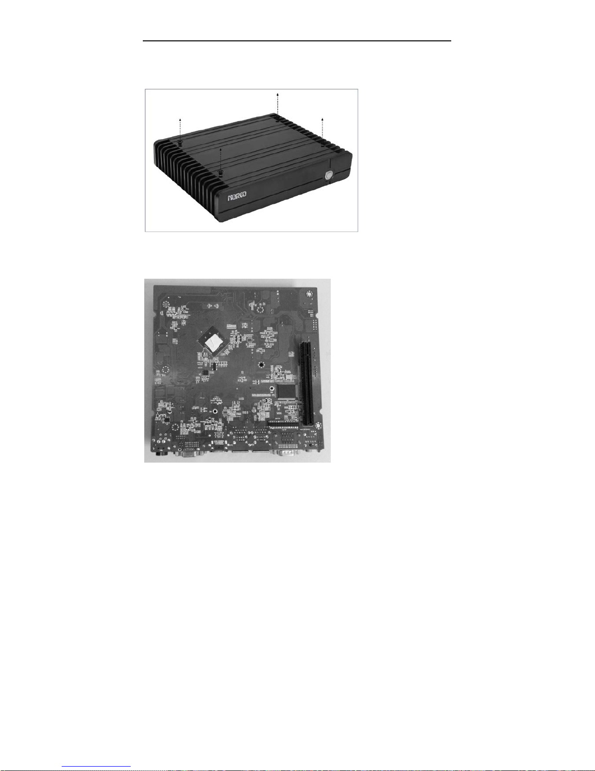
2.1Remove the Computer Cover
2.2 Install Motherboard
2.2.1 Install Thermal Pad
Remove the four
screws on cover
and dismount the
cover
The thermal pad is
tailored as per the size
of CPU and Chipset
and is pressed on to
the CPU and
Southbridge evenly
with fingers.
BIS-6660C User Manual
6
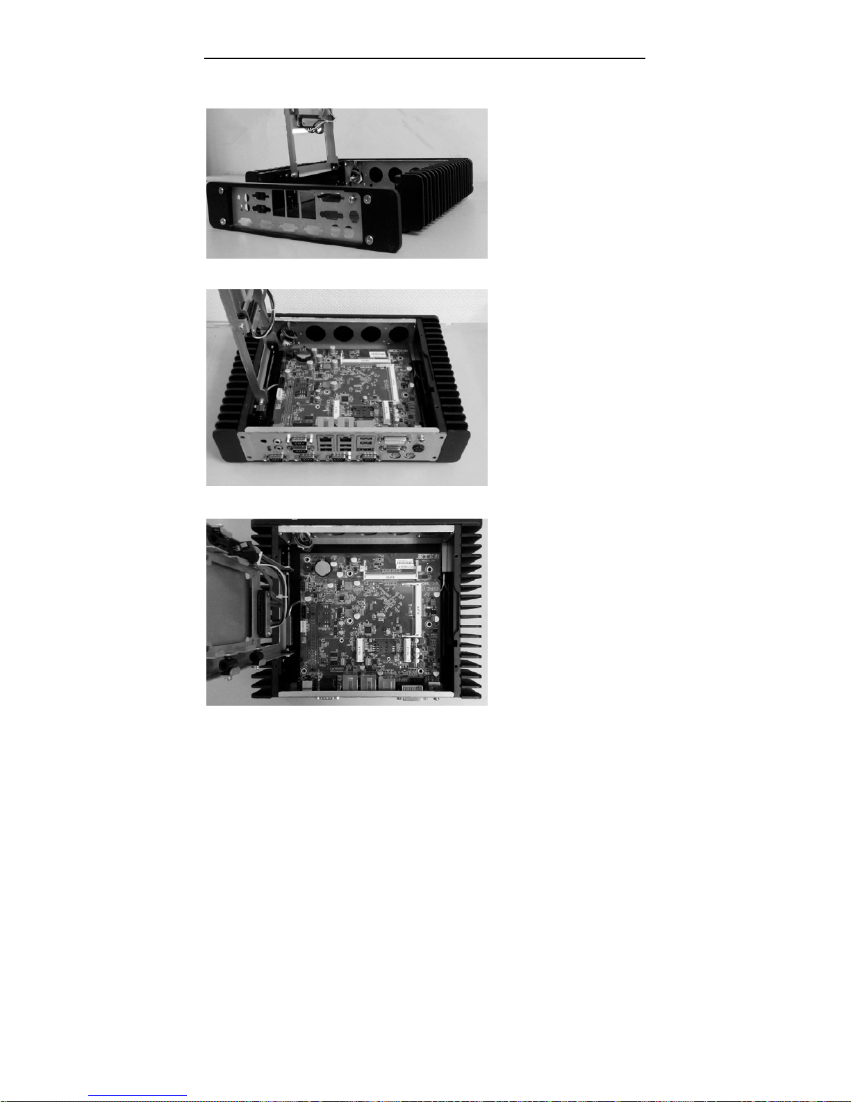
2.2.2 Dismount Rear Panel
2.2.3 Install the Motherboard
Loosen the four
screws on the side
of the rear panel and
remove the rear
panel module.
Align the semi-circle guide
holes of the motherboard
with the four guide posts on
the bracket and place the
motherboard on the bottom
cap evenly.
Tighten the 7 screws
onboard that fix the
motherboard (M3x6mm
screw x7PCS)
BIS-6660C User Manual
7
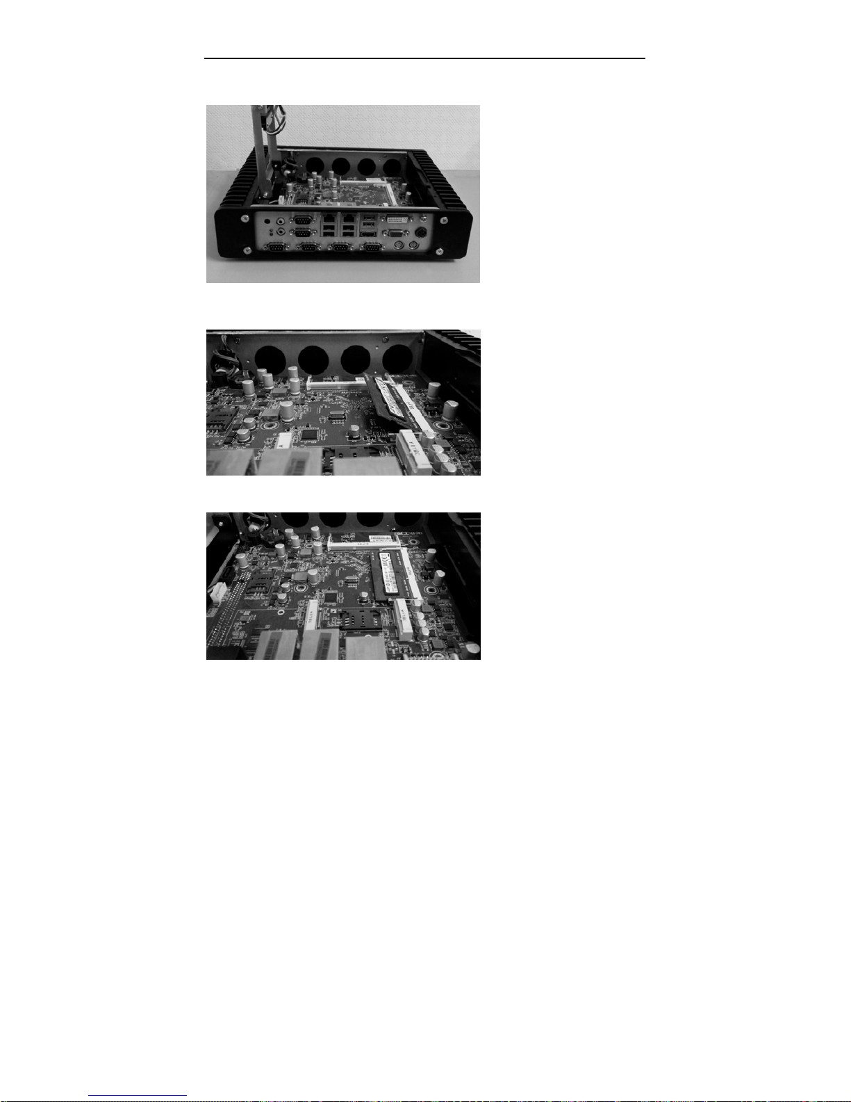
2.2.4 Mount Rear Panel
2.3 Install RAM
Mount back the rear panel
and tighten the four screws
on panel
Align the memory bank
with the memory slot in the
direction of 45 degree and
then insert the memory
into its socket.
Press the end of the
memory bank down into
the socket with fingers
until the memory bank is
fixed in the socket.
BIS-6660C User Manual
8
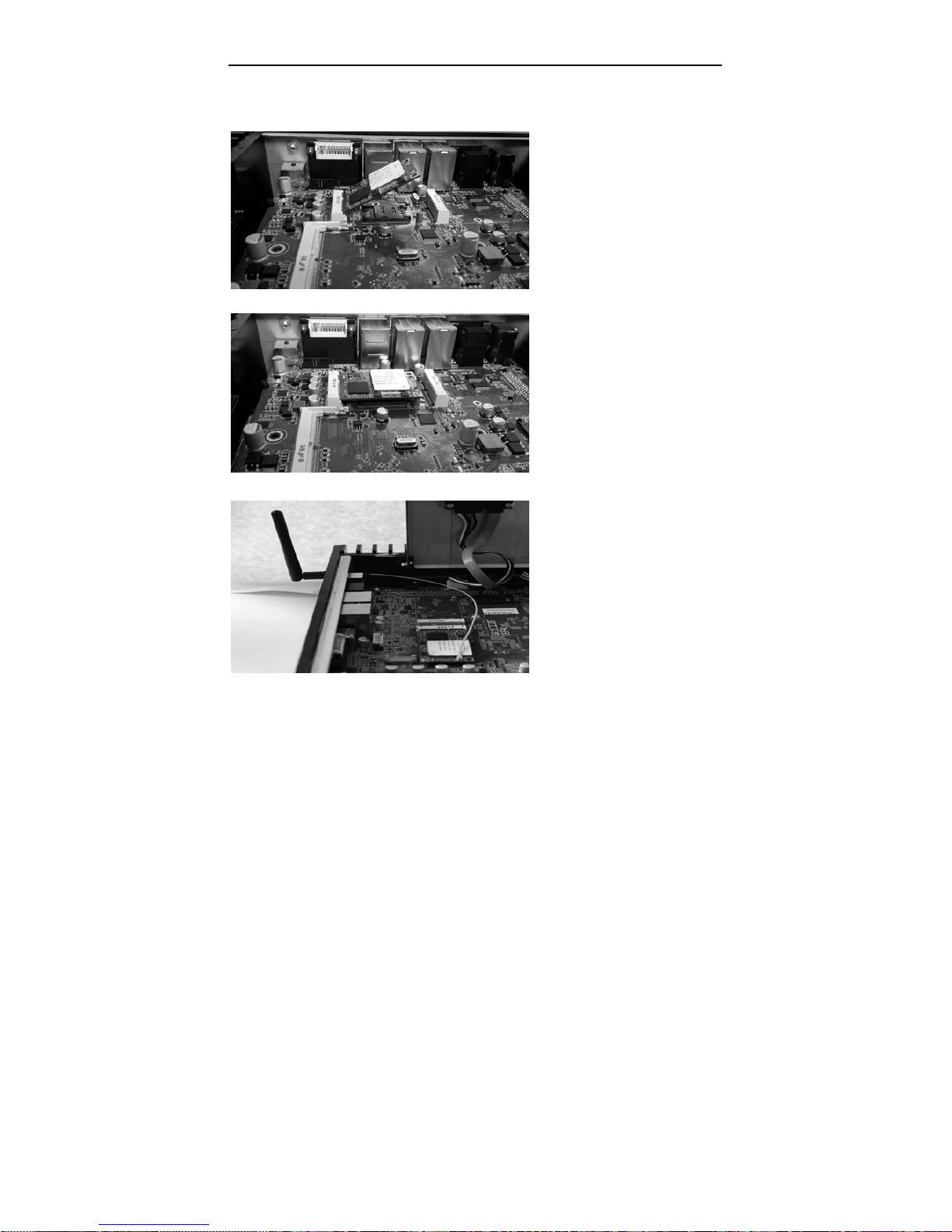
2.4 Install MINI PCIE Devices
Remove the screws onboard
for fixing the Mini PCIe
devices. Then insert the
device into the socket at a
45 degree angle.
Push against the end of the
Mini PCIe device and press
it down into the socket,
finally tighten the screws.
If the Mini PCIe device has a
WiFi antenna, please connect
the Antenna connector to the
WiFi Antenna hole on the rear
panel and then connect the
connector with Mini PCIe
device inside the chassis.
BIS-6660C User Manual
9
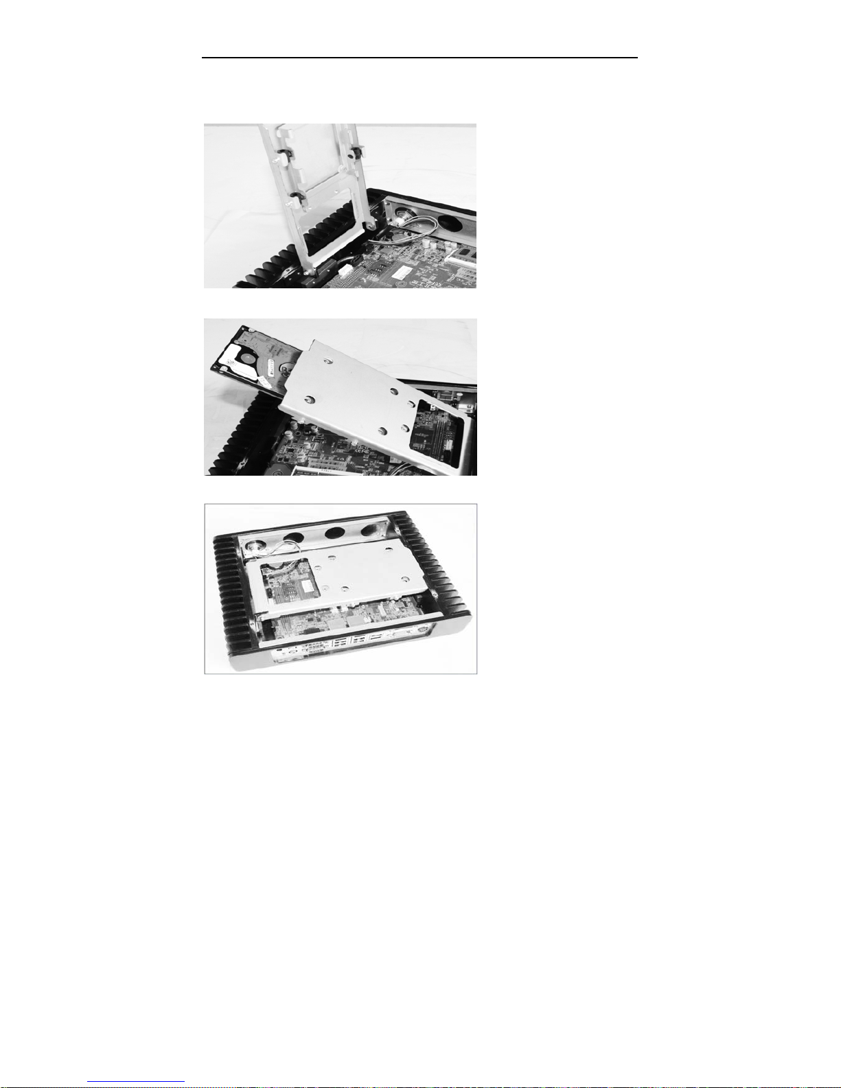
2.5 Install Hard Disk
Pull the HDD tray
upward at a 90 degree
angle.
Insert the hard disk
into the HDD tray.
Then close the HDD
tray.
BIS-6660C User Manual
10
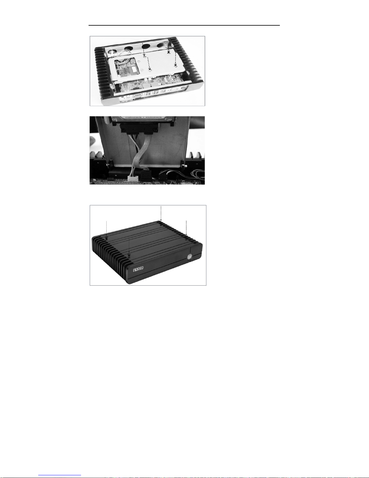
2.6 Mount the Top Cover
Use the screwdriver to
tighten the four screws on
the tray , so as to fix the
hard disk.
(M3x4mm screws x4PCS)
Connect the HDD power
cable and data cable to the
HDD port and use screws to
fix them and then connect
the other end of the cable to
the corresponding ports on
the motherboard.
Mount the computer top
cover and tighten the four
screws on the cover.

BIS-6660C User Manual
11
2.8 Rack Dimension

Chapter 3. Hardware
Functions

BIS-6660C User Manual
13
Chapter 3 Hardware Functions
3.1 External Interfaces Location
1:BIS-6660C Rear View
2:BIS-6660C Front View
3.3.1 Serial Ports(COM1, COM2)
Board provides 2x serial ports. COM1/ COM2 are standard DB9 serial ports. COM1/2 supports
RS232.

BIS-6660C User Manual
14
COM1, COM2:
Pin Signal Name
1 DCD
2 TXD
3 RXD
4 DTR
5 GND
6 DSR
7 RTS
8 CTS
9 RI
3.3.2 USB Ports(USB12, USB34, USB56)
BPC-7940 provides 4x standard double layer USB2.0 ports and one double-layer USB3.0.
(USB5 is USB2.0)
USB12,USB34, USB56:
Pin Signal Name

BIS-6660C User Manual
15
1 +5V
2 USB DATA-
3 USB DATA+
4 GND
3.3.3 Ethernet Ports(LAN1, LAN2)
BPC-7940 provides 2x RJ-45 Gigabit LAN ports. Both sides of the RJ-45 interface has one LED
lamp. The yellow one indicates data transfer status. The green one indicates network link
status.
RJ45 LAN LED Status
LILED(Green)
Function
ACTLED(Yellow)
Function
On 100/1000M link Flash Data transfer
Off 10M link/Close Off No data
3.3.4 Audio(Line-out, Line-in, MIC-in)
Motherboard BPC-7940 adopts ALC662 audio chip. The green one is Line-out. The pink one is
Mic-in. inbuilt one 1x 3Pin Line-in expansion interface.

BIS-6660C User Manual
16
3.3.5 Display Ports(VGA, DVI-D, HDMI)
Motherboard BPC-7940 provides one standard 15Pin VGA port to connect VGA display; 1x
DVI-D to connect DVI-D display and one 2x10Pin HDMI port.
VGA:
Pin Signal Name Pin Signal Name Pin Signal Name
1 RED 6 GND 11 NC
2 GREEN 7 GND 12 SDA
3 BLUE 8 GND 13 HSYNC
4 NC 9 +5V 14 VSYNC
5 GND 10 GND 15 SCL
DVI-D:
Signal Name Pin Signal Name
TDC2# 1 2 TDC2
GND 3 4 NC
NC 5 6 SC-DDC
SD-DDC 7 8 NC
TDC1# 9 10 TDC1
GND 11 12 NC
NC 13 14 VCC
GND 15 16 HP-DETECT
TDC0# 17 18 TDC0
GND 19 20 NC
NC 21 22 GND
TLC 23 24 TLC#
NC C1 C2 NC
NC C3 C4 NC

BIS-6660C User Manual
17
HDMI:
Signal Name Pin Signal Name
VCC 1 2 VCC
GND 3 4 GND
LA_DATA_N0 5 6 L_DDC_DATA
LA_DATA_P0 7 8 L_DDC_CLK
GND 9 10 GND
LA_DATA_N1 11 12 LA_CLK_N
LA_DATA_P1 13 14 LA_CLK_P
GND 15 16 GND
LA_DATA_N2 17 18 LA_DATA_N3
LA_DATA_P2 19 20 LA_DATA_P3
3.3.6 PS/2
System provides standard keyboard and mouse connector, to converted to standard PS/2
keyboard and mouse connector with an adapter cable.
KM:
Pin Signal Name
1 KB_DATA/ MS_DATA
2 NC
3 GND
4 +5V
5 KB_CLK/ MS_CLK
6 NC
3.2.1 CMOS Clear/Hold Jumper Setting(JCC)
CMOS is powered by the onboard button cell. Clear CMOS will lead to permanent elimination

BIS-6660C User Manual
18
of previous system settings and back to the original system setting (factory default).
Steps:
(1)Turn off the computer and disconnect the power supply;
(2)Use jumper cap short JCC Pin1 and Pin2 for seconds ( Pin1-2) and then restore the
default setting with Pin2-3 connected;
(3)Turn on the computer, then press “DEL” key to enter BIOS setting and reload optimal
defaults;
(4)Save and Exit.
JCC:
Setting JCC
1-2 Clear CMOS; BIOS back to factory default
2-3 Normal Status, System Default
Do not clear CMOS when the computer is still connected to power supply, otherwise, it
will cause damage to the motherboard.

BIS-6660C User Manual
19
3.2.2 Auto Boot upon Power Up(JAT)
JAT:
Setting JAT
Open Disable the auto boot function
Close Enable the auto boot function
3.3 Inner Interfaces
3.3.1 SATA Port(SATA)
The motherboard provides one standard 7Pin SATA port and one 5Pin SATA power interface.
The SATA power interface (JSATAPWR) is used to provide power supply to hard disk with an
extension cable.

BIS-6660C User Manual
20
SATA:
Pin Signal Name
1 GND
2 TX+
3 TX-
4 GND
5 RX-
6 RX+
7 GND

BIS-6660C User Manual
21
3.3.3 Power Interface(DC_JACK)
DC_JACK:
Pin Signal Name
1 +12V
2 GND
3 NC
3.3.4 Front Panel Interface(JFP)
JFP is used to connect the function buttons and LED lamps on the chassis front panel.

BIS-6660C User Manual
22
JFP:
Signal Name Pin Signal Name
POWER LED+ 1 2 POWER LED-
HD LED+ 3 4 HD LED-
VCC 5 6 BUZZDATA-
RESET SW 7 8 GND
POWER SW 9 10 GND
Please follow the table below to connect, pay attention to the anode (+) and cathode (-),
otherwise, some function cannot be realized.
POWER LED
HDD LED
BUZZ
RESET SW
PWR SW

BIS-6660C User Manual
23
1)System Power LED Pins(Pin1/2 for PWRLED)
Connect system power LED cable with these pins.(pin 1 is LED anode)When system is power
on, power LED is on;when system is power off, power LED is off.
2)HD LED Pins(Pin3/4 for HDD LED)
There is one HD LED on the case panel indicating HD status. When the hard disk reads and
writes, the LED will flash, indicating the device is working. Connect the LED cable to the LED
pins ( Pin3 is LED anode).
3)Buzzer Pins(Pin5/6 for SPEAKER)
External Speaker Pins
4)Reset Button Pins(Pin7/8 for RESET)
Connect the reset button cable to these two pins. When system fails, reset button can make the
system continue to work and no need to turn on / off the power.
5) Power Button Pins(Pin 9/10 for POWER BUTTON)
Connect these two pins to the bounce switch on the chassis to power on or power off the
machine.
3.3.5 SO-DIMM Slot
Board provides 2x dual channel SO-DIMM slots to support DDR3L 1333MHz memory up to
8GB.
3.3.6 MINI PCIe Socket(MINI PCIe1, MINI PCIe2, J10, J11)
Board provides 2x MINI PCIe slots. If you use the Mini PCIE WiFi, the status of which will be
determined by the wireless network that you choose.(MINI PCIe1 supports standard MINI PCIe
port and 3G module; MINI PCIe2 supports standard MINI PCIe port and EPC/mSATA SSD
optional(two functions alternative ). J10 is the LED for Mini PCIe1 device. J11 is the LED for
Mini PCIe2 device.

Chapter 4. BIOS SETUP

BIS-6660C User Manual
24
Chapter 4 BIOS SETUP
AMI BIOS FLASH
BIOS functions as a bridge connecting hardware and operating system. Hardware and
software are upgrading all the time, so when your system goes wrong, for example, your
system can not support the newest CPU, you need to upgrade BIOS to keep up with the latest
technology.
FPT64.EFI is the FLASH IC read-write program to load motherboard BIOS, which needs to be
run under Shell.
Press F11 when the computer starting up, select UEFI: Built-in EFI Shell to enter Shell, then
enter the device that stores BIOS (e.g. fs0 :). Then use FPT64.EFI to upgrade the BIOS(e.g.
write****.ROM into FLASH IC).
Operational Commands:
A:\ FPT64.EFI -f ****.bin
Note:
1. BIOS Flash is only executed when it is necessary
2. Please use the BIOS SETUP Utility in the CD-ROM provided by us or download the latest
version on related websites
3. Please do not power off or reboot the system when flash BIOS, otherwise, the BIOS may be
damaged or system may not be able to boot again.
4. After finishing BIOS Flash, load the optimal defaults manually
5. To prevent any unexpected problems, please backup your BIOS in advance.
AMI BIOS Description
When the computer is power on, BIOS will conduct self-diagnosis to its hardware on
motherboard and configure hardware parameter; finally the operating system will take control.
BIOS is the communication bridge between hardware and O/S. Correct configuration of BIOS
is critical for maintaining system stability and its optimized performance.
BIOS Setting
1. Power on or restart the system, self-detection message will display on the screen.

BIS-6660C User Manual
25
2. When system pops out the prompt "Press <Del> to enter setup, <F11> to Popup menu”,
please press <Del> key to enter BIOS setup interface.
3. Use the “←↑→↓”to select the option which your want to modify, press <Enter> to go to the
sub-menu.
4. Use the “←↑→↓”and <Enter> to modify the value; press”Enter” to modify BIOS options that
you choose.
5. At any time, press<Esc> can go back to the father-menu.
3.1 Main Menu
BIOS Vendor :BIOS Vendor information, American Megatrends
BIOS Version :7940I101
Build Date and Time :BIOS build date and time 04/11/2014 13:35:11
CPU Information :CPU information including CPU vendor, model, etc
Memory Information : Memory information including memory size, frequency, etc

BIS-6660C User Manual
26
System Date
System date format: Month (Jan.-Dec.)/Date (01-31)/Year (up to 2099)/Week (Mon.~Sun.).
System Time
System time format: Hour (00-23)/Minute (00-59)/Second (00-59).
3.2 Advanced
Launch LAN1/2 PXE OpROM
Enable or disable Boot Option for Legacy Network Devices.
ACPI Settings: ACPI sleep mode setting: S1/ S3.
Super IO Configuration: Super IO configuration including COM IRQ and addresses setting.
H/W Monitor: hardware health monitoring.
APM Configuration: RTC setting.
Serial Port Console Redirection: Serial port redirection.
CPU Configuration: CPU parameters setting
PPM Configuration: CPU Power Management

BIS-6660C User Manual
27
SATA Configuration: Hard disk mode setting and other info.
LPSS&SCC Configuration: OS options.
Network Stack Configuration: Load onboard UEFI LAN card boot code or not.
CSM Configuration: Compatibility support module control options.
USB Configuration: USB information and setting
3.2.1 ACPI Configuration
ACPI Sleep State
Select highest APCI sleep state the system will enter when the SUSPEND button is pressed.
Different modes will have different power consumption.
[Suspend Disabled]: shut off the system and sleep;
[S3]: Only Suspend to Ram.

BIS-6660C User Manual
28
3.2.2 Supper IO Configuration
Serial Port 1 Configuration
Serial Port 2 Configuration
Serial Port 3 Configuration
Serial Port 4 Configuration
Serial Port 5 Configuration
Serial Port 6 Configuration
Serial Port 7 Configuration
Serial Port 8 Configuration
Serial Port 9 Configuration
Serial Port 10 Configuration
Watch Dog Configuration

BIS-6660C User Manual
29
Serial Port 1 Configuration
1)Serial Port
Enable or disable the serial port function.
2)Device Setting(Read Only)
This option shows the serial port IRQ and addresses.
3)Change Setting
Set serial port IRQ and Address.
Serial Port 2-10 Configuration
Serial Port 2-10 Configuration is the same as the above.

BIS-6660C User Manual
30
WDT Timeout Mode
WDT Timeout Mode Select: Minute or Second and it will show the submenu WDT Timeout
Value (0-255). System defaults [Disabled].

BIS-6660C User Manual
31
3.2.3 H/W Monitor
PC Health Status
PC Health Status Detect. BIOS will display current system temperature, CPU temperature,
FAN rotate speed, and related voltage value.

BIS-6660C User Manual
32
3.2.4 APM Configuration
RTC Power On Function
Enable or Disable System wake on alarm event. When enabled, System will wake on the
hr::min::sec specified.
RTC Power On Hour
To set system wakes on the specific hour.
RTC Power On Minute
To set system wakes on the specific Minute.
RTC Power On Second
To set system wakes on the specific Second.

BIS-6660C User Manual
33
3.2.5 Serial Port Console Redirection

BIS-6660C User Manual
34
Console Redirection
Console Redirection. Board supports COM1 /COM2 console redirection. Default [Disable]. To
enable the console redirection is only need to enable COM1 or COM2 console redirection. No
need to enable EMS redirection.
General Options:
1. Console Redirection
2. Terminal Type: including VT100/VT100+/ VT-UTF8/ANSI. If the terminal console has
unreadable code, please adjust this option. System default [VT100+].
3. Bits per Second: Baud Rate setting. Default [115200].
The Emergency Management Services (EMS), available in Windows Server 2003 and
Windows Server 2008, provides “headless” support for today enterprise servers. It enables
management services without the need for a keyboard, mouse, local monitor, and video
adapter. A server administrator interacts with EMS through a Special Administration Console
(SAC) to perform management and recovery tasks, even when the system’s operational status
is questionable. There is no need to enable EMS redirection when enabling serial port console
redirection.

BIS-6660C User Manual
35
General Settings:
1. Out-of-Band Mgmt Port: serial port number setting
2. Terminal Type: Terminal types include VT100/VT100+/ VT-UTF8/ANSI. If system gets
unreadable code of the terminal console, you need to adjust this option. Default
[VT100+].
3. Bits per second: Baud Rate setting.
3.2.6 CPU Configuration
Socket 0 CPU Information
CPU Information
Active Processor Cores
To active all processor cores or not(only for the multi-core processors)
Limit CPUID Maximum

BIS-6660C User Manual
36
The CPUID instruction of some newer CPUs will return a value greater than 3. The default is
disabled because this problem does not exist in the Windows series operating systems. If you
are using an operating system other than Windows, this problem may occur. To avoid this
problem, please enable this field to limit the return value to 3 or lesser than 3. Default
[Disabled].
Execute Disabled Bit
Execute Disable Bit (EDB) is a hardware-based security feature that introduced to its new
generation CPU by Intel, which can help reduce system exposure to viruses and malicious
code. EDB allows the processor to classify areas in memory where application code can or
cannot execute. To use Execute Disable Bit you must have Windows XP SP2 operating system
to support this function.
Hardware Prefetcher
Whether the processor allows the Intel hardware prefetcher to fetch streams of data and
instruction from memory into the unified second-level cache when necessary. This can be one
of the following:
Disabled—The hardware prefetcher is not used.
Enabled—The processor uses the hardware prefetcher when cache issues are detected.。
Adjacent Cache Line Prefetch
Whether the processor fetches cache lines in even/odd pairs instead of fetching just the
required line. This can be one of the following:
Disabled—The processor only fetches the required line.
Enabled— The processor fetches both the required line and its paired.
Intel Virtualization Technology
Intel virtualization technology enables to run multiple O/S of the same kind or different kind by
using the same physical platform so as to realize the management and allocation of computer
resources, maximizing the resource utilization.
Power Technology
Power Management

BIS-6660C User Manual
37
The read only option contains detailed information of CPU, including CPU manufacturer,
model, frequency, L1 Cache, L2 Cache, etc.

BIS-6660C User Manual
38
3.2.7 PPM Configuration
EIST
Enhanced Intel Speed Step Technology (EIST) is a power and thermal management
technology developed by Intel. Enhanced Intel Speed Step Technology allows the system to
dynamically adjust processor voltage and core frequency, which can result in decreased
average power consumption and decreased average heat production. Ensure it is set to
"Enabled."
CPU C state Report
Enable or disable the CPU C-states.

BIS-6660C User Manual
39
3.2.8 SATA Configuration
Serial-ATA Controller(S)
Enable or disable the Serial-ATA Controllers. Setting options: [Disabled], [Enhanced],
[Compatible].
SATA Speed Support
Supported SATA speed
SATA Mode
Select SATA mode
Serial-ATA Port 0
Enable or disable SATA Port0
SATA Port 0 Hotplug
Enable or disable SATA Port0 hot plug

BIS-6660C User Manual
40
Serial-ATA Port 1
Enable or disable SATA Port1
SATA Port 1 Hotplug
Enable or disable SATA Port1 hot plug
3.2.9 LPCC&SCC Configuration
OS Selection:
Select OS to install.

BIS-6660C User Manual
41
3.2.10 Network Stack Configuration
UEFI LAN1/2 PXE OpROM
Enable or disable UEFI LAN1/2 PXE OpROM. System default [Disable].
Ipv4 PXE Support
PXE supports IPV4
Ipv6 PXE Support
PXE supports IPV6
PXE boot wait time
PXE boot wait time

BIS-6660C User Manual
42
3.2.11 CSM Configuration
CSM Support
CSM is short for Compatibility Support Module, which is a special module of UEFI, offering
compatible support for those systems that unsupport UEFI.
GateA20 Active
Activate GateA20
Option ROM Messages
Optional ROM Messages
INT19 Trap Response
INT19 Trap Response
Boot opdtion fildter

BIS-6660C User Manual
43
Boot opdtion fildter
Network
Network Boot Setting
Storage
Storage Select
Video
Display Setting
Other PCI devices
Other PCI devices
3.2.12 USB Configuration
Legacy USB Support
To support USB device in DOS mode: such as USB Flash Disk, USB keyboard, please select

BIS-6660C User Manual
44
<Enabled> or<Auto>.
If not, please select < Disabled>.
XHCI Support
USB3.0 Controller mode select. [Smart Auto]/[Auto] :system is able to auto shift to USB2.0 or
USB3.0. [Enable] only support USB3.0. [Disable] will close USB3.0 controller, but unable to
shift to USB2.0. Install USB3.0 driver under WIN7, XHCI Mode should be set as [Enable]. XP
has no USB3.0 driver. Win8 self-provide USB3.0 driver.
USB 2.0 (EHCI) Support
Enable or Disable the USB EHCI (USB 2.0) functions. One EHCI controller must always be
enabled.
[Enabled]: Enable USB EHCI (USB 2.0) functions, maximum transmission rate up to 480Mpbs
[Disabled]: Disable USB2.0 function. The transmission rate is 12Mpbs.
USB3.0 Support
Enable or disable USB3.0 support
XHCI Hand-off
This option is default [Enabled].
EHCI Hand-off
This option is default [Disabled]. System runs at USB1.1 compatible mode before entering OS.
USB Mass Storage Driver Support
Enable or disable USB mass storage driver support.
USB Transfer time-out
USB Transfer time-out: set control, batch and interrupt transmission timeout. Default
[20seconds].
Device reset time-out
Device reset time-out: Set Mass USB disk boot command timeout. Default [20seconds].

BIS-6660C User Manual
45
Device Power-up Delay
Device Power-up Delay: Set the maximum delay time that USB device takes to report to the
master controller.
USB Mass Storage Device
Set the types of the connected USB devices. [Auto], [floppy], [Forced FDD], [HDD] or CD-ROM.
System defaults as [Auto].
3.3 Chipset Menu
North Bridge
North Bridge Configuration
South Bridge

BIS-6660C User Manual
46
South Bridge Configuration
3.3.1 North Bridge
Integrated Graphics Device
Enable: Enable Integrated Graphics Device (IGO) when selected as the Primary video Adaptor.
Disable: Always disable IGO
Primary Display
The primary Display device when system boots.
DVMT pre-AIIocated
Dynamic video memory size
DVMT Total Gfx Mem
Total dynamic memory size

BIS-6660C User Manual
47
3.3.2 South Bridge
Audio Controller
Enable or disable the onboard audio controller.
Azalia HDMI Codec
Enable or disable Azalia HDMI Codec.
LAN 1/2 Controller
Enable or disable onboard LAN1/2 Controller.
Restore AC Power Loss
This option is to setup the system status while connecting the power again after the AC Power
Loss
<Power Off>:System remains the status of power off. Users need to press the power button to
start the computer.
<Power On>: System will reboot automatically when connecting to power supply.
<Last State>: Remain the same state as that before the power loss.

BIS-6660C User Manual
48
3.4 Boot Menu
Setup Prompt Timeout
Number of seconds to wait for setup activation key. 60s is the max seconds of timeout. If don’t
press Setup activation key within the preset time, system will contiune to start.
Bootup Numlock State
This function allows users to activate Numlock function when boot up.
[ON]:Numlock is activated when system boots up
[OFF]: Numlock under cursor control.
Show Full Logo
[Enabled]: Computer boot screen will show supplier’s LOGO.
[Disabled]: Self-detect info will show when system boots.
Boot Option Priorities

BIS-6660C User Manual
49
System will detect devices according to the preset sequence until to find a boot device. Option
#1 is the prior boot device.
Hard Drive BBS Priorities
This option contains HDD that can be used as boot device. If multiple HDDs in this option,
priority should set for these HDDs, then the prior one will show in Boot Option #1.
3.5 Security Menu
The password length: Min: 1 character, Maximum: 20 characters.
Administrator Password
Set administrator password.
User Password
Set user password.

BIS-6660C User Manual
50
3.6 Save & Exit Menu
Load Defaults
Restore/Load Default values for all the BIOS setup options.
Save Changes and Exit
Press [Enter] to select this option and press [Enter] to confirm to save all BIOS changes and
Exit.
Discard Changes and Exit
Press [Enter] to select this option and press [Enter] to confirm to discard all changes and exit.
Boot Override
This option list all boot options. Users can select one option and press <Enter>, then system
will boot from this option.

Appendix

BIS-6660C User Manual
51
Appendix
Appendix 1: Install Driver
Please install the driver as per the following steps:
Insert the programmed disk into CD-ROM, so installation of the driver can be made either
automatically or manually. Now manually installation instructions are given as below:
1) A variety of options are available regarding manually installation, which you can check from
Device Manager.
2) Right click “my computer ", select "management", and go to “Device Manager"
3) Right click "display controller” in the menu of graphic card, select “Properties ", click “Driver",
select “update driver".
4) Select “Show the list of all drivers which are designated locations so that choices can be
made from it ", select "next."
5) Select the location of display driver, click “ok"
6) Complete the installation, restart the system.
Proceed with the installation of other drivers after restarting the system, till all installations are
completed. Then user can check from the device manager that it says device is working.

BIS-6660C User Manual
52
Appendix 2:Watchdog Programming Guide
watchdog reference code(C)
Write data to corresponding ports in C language to realize different functions of Watchdog
Time r.
Port Instruction:
void main()
{
int indexp = 0x4e,datap = 0x4f;
unsigned char temp;
Outportb(indexp,0x87);
Outportb(indexp,0x87); //unlock
Outportb(indexp,0x2d);
temp = (unsigned char) inportb (datap);
temp &= 0xfe;
Outportb(indexp,0x2d);
Outportb(datap,temp); //set pin for watchdog
Outportb(indexp,0x07);
Outportb(datap,0x08);
Outportb(indexp,0x30);
Outportb(datap,0x01); //enable logical device
Outportb(indexp,0xf5);
Outportb(datap,0x00); //set second
Outportb(indexp,0xf6);
Outportb(datap,0x05); //set 5seconds
Outportb(indexp,0xf7);
Outportb(datap,0x00);
Outportb(indexp,0xaa); //lock
}
If the system crashes, Watchdog enables system to auto reboot.

BIS-6660C User Manual
53
Appendix 3: Glossary
ACPI
Advanced Configuration and Power Management. ACPI specifications allow O/S to control
most power of the computer and its add-ons
BIOS
Basic input/output system. It is a kind of software including all in/out control code interface in
PC. It will do hardware testing while system is booting, and then the O/S runs. BIOS provides a
interface between O/S and hardware and is stored in a ROM chip.
BUS
In a computer system, it is the channel among different parts for exchanging data; it is also a
set of hardware lines. BUS here refers to part lines inside CPU and the main components of
system memory.
Chipset
Chipset is a Integrated set of chips for executing one or more related functions。Here it refers to
a system level chipset structured by Southbridge & Northbridge; It decides the structure and
main functions of motherboard.
CMOS
Complementary Metal-Oxide Semiconductor, which is a widely used semiconductor with the
characteristics of high-speed and low-power. COMS here refers to part of space on-board
CMOS RAM for saving date, time, system information and system parameter, ect.
COM
Computer-Output Microfilmer. A universal serial communication interface, usually adopts
normative OB 9 connector.
DIMM
Dual-Inline-Memory-Modules. It is a small circuit board with memory chipset providing 64 bit

BIS-6660C User Manual
54
memory bus width.
DRAM
Dynamic Random Access Memorizer. It is a normal type of memory often with a transistor and
a capacitance to store 1 bit. With the development of the technology, more and more types of
DRAM with different specifications exist in computer applications. For example: SDRAM/DDR
SDRAM/RDRAM.
LAN
Network interface. Network grouped by correlative computers in a small area, generally in a
company or a building. Local area network is buildup by sever, workstation, some
communications links. Terminals can access data and devices anywhere through cables,
which enables users to share costly devices and resource.
LED
Light-Emitting Diode.A semiconductor device that shines when power supply is connected, It is
often used to denote information directly, for example, to denote power on or HDD working
normally.
PnP
Plug-and-Play. It is a specification that allows PC to configure its external devices automatically
and can work independently without the manual operation by its user . To achieve this function,
its BIOS should be able to support PnP and a PnP expansion card.
POST
Self-test when power on. While the system is booting, BIOS will do an uninterrupted testing to
the system, including RAM, keyboard, hard disk drive etc. to check if all the components are in
normal situation and work well.
PS/2
A keyboard & mouse connective interface specification developed by IBM.PS/2 is a DIN
interface with only 6PIN; it also can connect other devices, like modem.

BIS-6660C User Manual
55
USB
It is the Universal Serial Bus for short. A hardware interface adapts to low speed peripherals,
and is always used to connect keyboard, mouse etc. One PC can connect maximum 127
USB devices, providing 12Mbit/s transmit bandwidth USB supports hot swap and multi- data
stream, namely, you can plug USB devices while system is running, system can auto-detect
and makes it work on.

 Loading...