

Norco BIS-6620 User Manual

BIS-6620
Mini PC
USER' Manual V1.0

SZ HQ: 0755-27331166
BIS-6620
Mini PC
USER' Manual V1.0
Beijing Office: 010-82671166
Shanghai Office: 021-61212081
Chengdu Office: 028-85259319
Shenyang Office: 024-23960846
Xi’an Office: 029-88338386
Nanjing Office: 025-58015489
Wuhan Office: 027-87858983
Tianjin Office: 022-23727100
Singapore: 65-68530809
For more information, please visit:www.norco.com.cn

Disclaimer
Except for the accessories attached to the product as specified herein,
what is contained in this user manual does not represent the commitments
of NORCO Company. NORCO Company reserves the right to revise this
User Manual, without prior notice, and will not be held liable for any direct,
indirect, intended or unintended losses and/or hidden dangers due to
installation or improper operation.
Before ordering products, please learn about the product performance
from the distributors to see if it is in line with your needs. NORCO is a
registered trademark of Shenzhen NORCO Intelligent Technology CO., LTD.
The ownership of other trademarks involved in this manual is owned by its
respective owners.

Safety Instructions
1. Please read the product manual carefully before using this product.
2.Put all the unused or uninstalled boards or electronic components in a
static dissipative surface or static shielding bag.
3. Always ground yourself to remove any static discharge before touching
the board, to place your hands on grounding metal object for a while or wear
an anti-static wrist strap at all times.
4 . When taking or fetching the boards or cards, please wear anti-static
gloves and have the habit of holding the boards by its edges.
5. Make sure that your power supply is set to the correct voltage in your
area. Incorrect voltage may cause personal injuries and damage the system.
6.To prevent electronic shock hazard or any damage to the product, please
ensure that all power cables for the devices are unplugged when adding or
removing any devices or reconfiguring the system.
7.To prevent electrical shock hazard, disconnect the power cable from the
electrical outlet before relocating the system.
8.When adding or removing devices to or from the system, ensure that all
the power cables for the devices are unplugged in advance.
9 . To prevent any unnecessary damage to the products due to frequent
power on/off, please wait at least 30 seconds to restart the unit after the
shutdown.
10.If system goes wrong during the operation, do not try to fix it by yourself.
Contact a qualified service technician or your retailer.
11. This product is classified as Class A product, which may cause radio
interference in our living environment. On this occasion, users need to take
measures to handle the interference.

Content
Chapter One Product Introduction
1.1 Product Introduction..................................................................................................................1
1.2 Feature........................................................................................................................................1
1.3 Hardware Specificattion........................................................................................................... 2
1.4 Product Dimension....................................................................................................................3
Chapter Two Hardware Function
2.1 External Interface Indicator Diagram......................................................................................4
2.2 Jumper Settings.........................................................................................................................5
2.2.1 CMOS Clear/Hold Jumper Setting(JCC)
2.3 Interface Specification.............................................................................................................. 5
2.3.1 CF Card Slot(CF)
2.3.2 SD Card Slot(SD)
2.3.3 USB Port(USB1,USB2,USB3)
2.3.4 Audio Port(Line-out,Mic-in)
2.3.5 Ethernet Interface(LAN)
2.3.6 Keyboard and Mouse Interfaces(Ms/Kb)
2.3.7 Power Interface(DC +12V)
2.4 BIS-6620III Expansion Board Interface................................................................................. 7
2.4.1 VGA Port(VGA)
2.4.2 Serial Port(COM)
2.5 BIS-6620IV Expansion Board Interface.................................................................................9
2.5.1 HDMI Port(HDMI)
2.5.2 SATA Port(SATA)
Chapter Three Hardware Installation
3.1 Remove Host Cover................................................................................................................11
3.2 Hardware Installation.............................................................................................................. 11
3.2.1Memory Module Replacement/Installation................................................................11
3.2.2 Hard Disk Replacement/Installation..........................................................................12
3.3 Wall Mounted / Display Installation...................................................................................... 13
3.4 Power Connection...................................................................................................................14
Chapter Four BIOS Setup
................................................................................................................
.................................................................................................
.................................................................................................
..............................................................
......................................................................................................
.....................................................................................................
..........................................................................
...................................................................................
...........................................................................................
..............................................................
......................................................................................
.........................................................................................................
......................................................................................................
.....................................................................................................
......................................................................................................
..........................................................................................
1
4
5
5
5
5
6
6
7
7
7
8
9
9
11
15

4.1 Main Menu................................................................................................................................17
4.2 Advanced Menu.......................................................................................................................18
4.2.1 CPU Configuration.......................................................................................................19
4.2.2 Super IO Configuration...............................................................................................21
4.2.3 Hardware Health Configuration................................................................................. 23
4.2.4 ACPI Configuration......................................................................................................24
4.2.5 MPS Configuration...................................................................................................... 28
4.2.6 Smbios Configuration..................................................................................................29
4.2.7 Remote Access Configuration................................................................................... 30
4.2.8 USB Configuration.......................................................................................................31
4.2.9 Onboard LAN Option ROM........................................................................................33
4.3 PCI PnP Menu.........................................................................................................................34
4.4 Boot Menu................................................................................................................................ 36
4.5 Security Menu..........................................................................................................................39
4.6 Chipset Menu...........................................................................................................................40
4.6.1 North Bridge Configuration.........................................................................................40
4.6.2 South Bridge Configuration........................................................................................43
4.7 Exit Menu..................................................................................................................................44
Appendix
................................................................................................................................................
Appendix 1:Driver Installation
...................................................................................................
Appendix 2:Embedding SATA Hard Drive into Windows XP Installation Disk
Appendix 3:Watchdog Programming Guide
Appendix 4:Glossary
..................................................................................................................
...........................................................................
..................
43
43
44
45
47

Chapter
One
Product
Introdu
ction

BIS-6620 Based on Menlow Platform Mini PC
1
Chapter One Product Introduction
1.1 Introduction
BIS-6620 is a compact and easy-to-use thin client,with the most popular Menlow platform
of Intel, the whole machine has powerful logic operation ability, the maximum power
consumption is only 5.5W, noise-free design, and multi-storage means of SATA, SD and CF
cards. The diversity of display terminals provides more choices for customers. Customized
expansion slots can improve the flexibility of peripheral expansion. BIS-6620 can be widely
used in high-definition media broadcasting, advertising machines, LCD large screen, set-top
box, medical care, finance, education and other terminal market and industrial occasions.
1.2 Feature
●Miniature shape, ultra-low noise, fuselage heat dissipation
BIS-6620 adopts fanless heat dissipation design; the whole machine only produces 30 dB
ultra-low noises when running. Exterior size is only120mm × 120mm × 40mm. It can be
applied to all kinds of narrow spaces.
●On board Intel Atom Processor
On-board low power consumption and high performance Intel Atom Z5XX series
processor,power consumption is only 2.5W,with Poulsbo SCH high speed chipsets constitute
the best solution for embedded platform.
●Rich interfaces
BIS-6620 has a lot of I/O interface on its backplane,including:Line-out jack、microphone
jack、USB2.0、RJ-45 network port. In addition, BIS-6620 also provides flexible expansion card
selection options, with the expansion card can have VGA+4xCOM output or HDMI+3xUSB
output.
●Various Installation Methods
BIS-6620 meets VESA MOUNT MIS-D standard. It can be mounted on the back of a
device such as a liquid crystal display or placed on a desktop.
BIS-6620 Based on Menlow Platform Mini PC
2
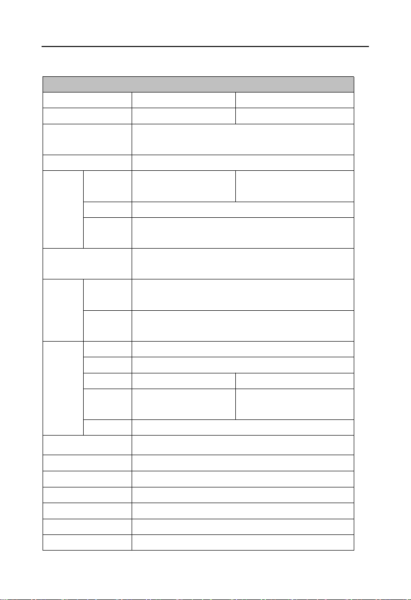
System
Model
BIS-6620III
BIS-6620IV
Motherboard
BPC-7652+AFC-341V
BPC-7652+AFC-450H
Processor
Intel Atom Z510(1.1GHz FSB400MHz)/Z530(1.6GHz
FSB533MHz)
Chipset
Intel Poulsbo SCH
Display
Display
Port
VGA
HDMI
Controller
Intel Poulsbo Integrate GMA500
Video
Memory
Dynamic sharing 256 MB system memory as display memory
System Memory
Provide 1xSO-DIMM,support DDR2(400/533MHz), memory
up to 1GB
Storage
SSD
1x card slot (panel interface),support Type II Compact
Flash,1xmultifunctional SD card reader
HDD
Built-in 1x1.8” hard disk bay, support Ultra DMA 100/66/33
and SATA II HDD
System
I/0
I/O Chip
Winbond W83627DHG
PS/2
1x Mouse and Keyboard
COM
4x COM(4 in 1)
--
USB
3xUSB2.0(2x preposition,
1x Built-in)
6x USB2.0(2x preposition,3x
postposition,1x Built-in)
Audio
1x Mic-in,,1x Line-out
Ethernet
Realtek RTL8111C,10/100/1000Mbps,1x RJ45
Expansion Interface
--
System Control
ON/OFF
LED Indicator Light
Power supply and hard disk indicator light
Power Supply
DC +12V
Cooling Fan
Fanless
OS
Windows Vista/XP/CE/XPE,Linux
1.3 Hardware Specification
BIS-6620 Based on Menlow Platform Mini PC
3
Environment-Physical Characteristics
Operating Temperature
-10℃~50℃
Storage Temperature
-40℃~60℃
Relative Humidity
5%~95%,non-condensing
Vibration Test
0.5g rms/5~500Hz/ Random
EMC
CE/FCC Class B
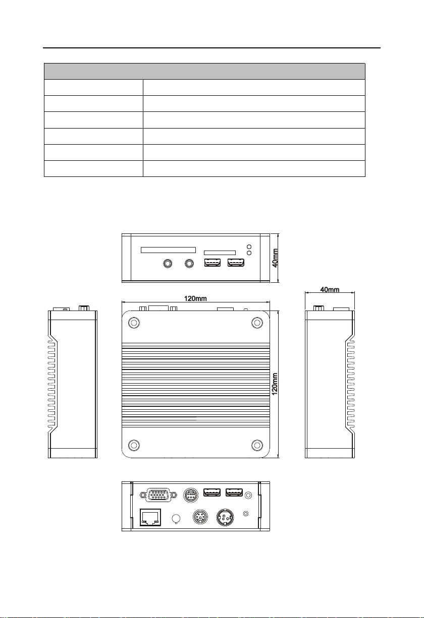
Dimension
120mm×120mm×40mm (L x W x H)
1.4 Product Dimension
Dimension:120mm x 120mm x 40mm(L x W x H)

Chapter
Two
Hardware
Function
BIS-6620 Based on Menlow Platform Mini PC
Chapter Two Hardware Function
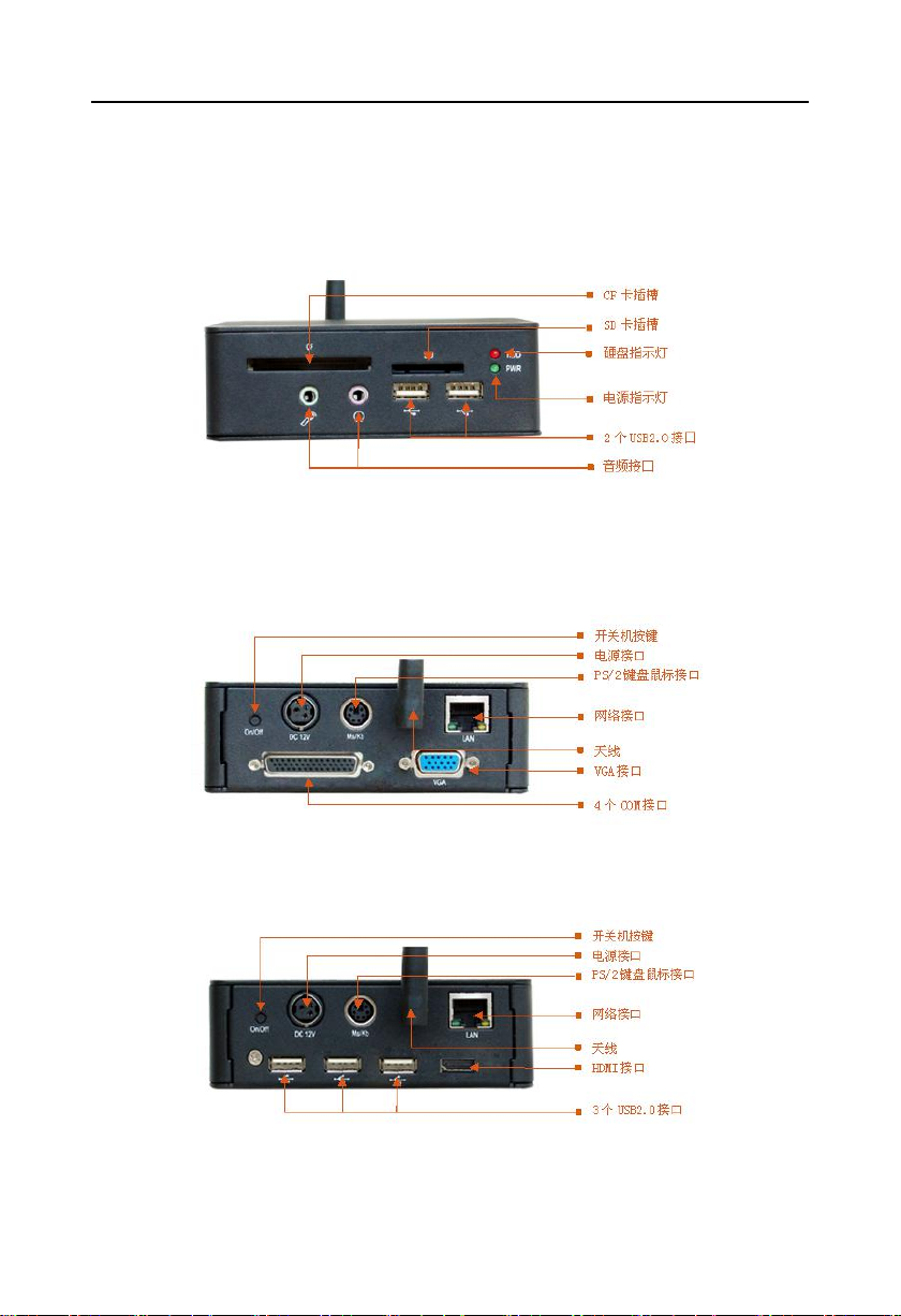
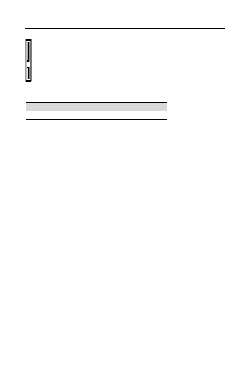
2.1 External Interface Indicator Diagram
1:BIS-6620 Front view
2:BIS-6620 Rear view
BIS-6620III:
BIS-6620IV:
4
BIS-6620 Based on Menlow Platform Mini PC
Setting
JCC
1-2
Clear CMOS Data, all BIOS setting back to factory
2-3
Normal working state, default setting(general)
2.2 Jumper Setting
Please refer to following instructions to do jumper settings before installing your hardware
devices.
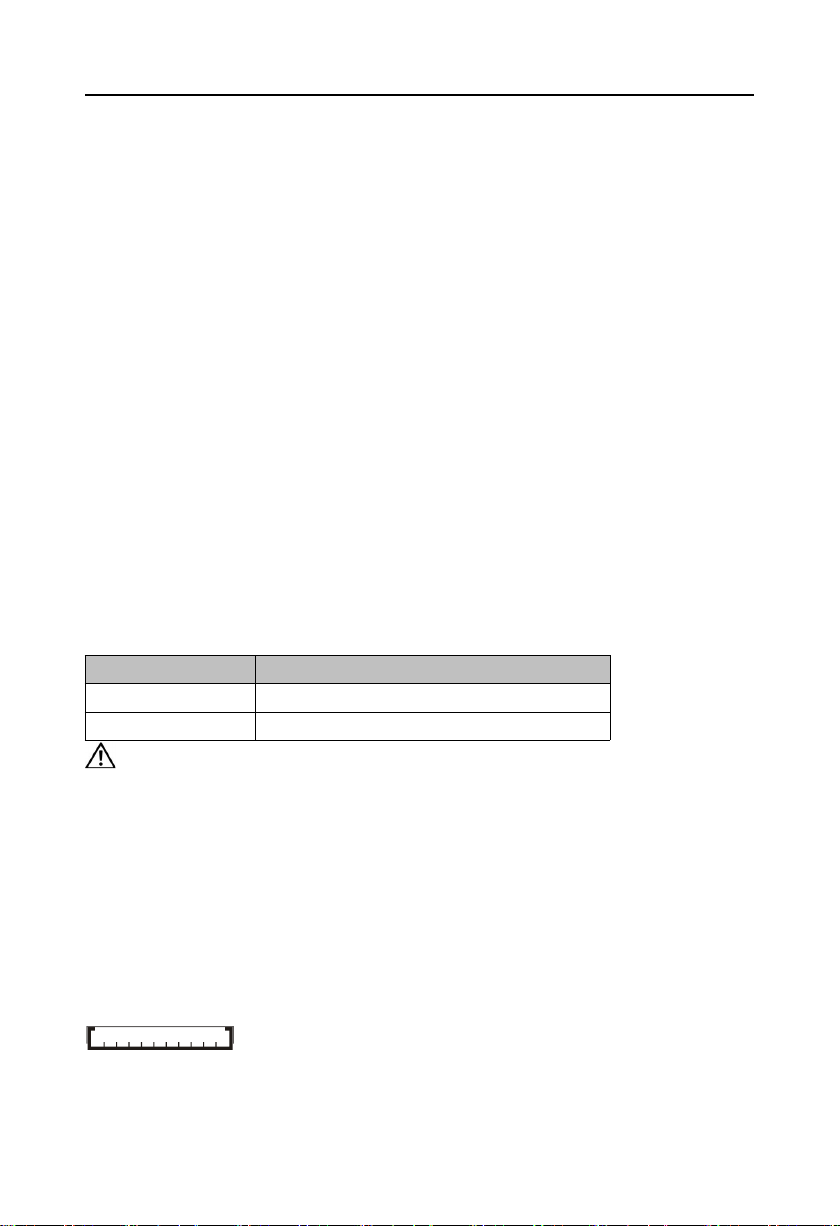
Remark: How to identify the PIN1 of all jumpers and interfaces: Please observe the mark near
the plug and socket, which is a “1” or bold line or triangular symbol; And please look at the back
of PCB, the one in the shape of square is the PIN 1; and PIN1 for every jumper is remarked by
a white narrow near it.
2.2.1 CMOS Clear/Hold Jumper Setting(JCC)
CMOS is powered by the onboard button cell. Clear CMOS will lead to permanent
elimination of previous system settings(factory default).
Steps:(1)Turn off the computer, disconnect power supply;
(2)Use jumper cap to connect JCC pins 1 and 2 for a few seconds (expressed as 1-2),
then restore to default setting 2-3;
( 3 ) Start the computer, then press “Del” to enter BIOS setting and reload optimal
defaults;
(4)Save and Exit.
Do not clear CMOS when the computer is powered on, otherwise, Damage will be
caused to the motherboard!
2.3 Motherboard Interface Description
2.3.1 CF card slot(CF)
BIS-6620III/IV provides 1x50Pin standard CF card slot,can support TypeⅠ/ⅡCF card.
2.3.2 SD card slot(SD)
BIS-6620III/IV provides 1x SD card slot,can support standard SD/MMC card.
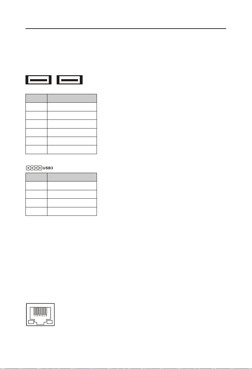
2.3.3 USB Port(USB1,USB2,USB3)
Motherboard provides 2x standard USB port(USB1,2)and one 4Pin USB port(USB3),
5
BIS-6620 Based on Menlow Platform Mini PC
Pin
Signal Name
1
VCC
2
USB_D-
3
USB_D+
4
GND
5
GND
6
GND
Pin
Signal Name
1
VCC
2
USB3-
3
USB3+
4
GND
compatible USB2.0 specification,support Plug and Play for standard USB devices. If you don't
want to use this port, you can disable the USB port in BIOS. 4Pin USB3 port is used to connect
optional WIFI wireless network card. USB3 port of 4Pin for connecting optional WIFI wireless
network card.
USB1,2:
2.3.4 Audio Port(Line-out,Mic-in)
BIS-6620III/IV adopt ALC888 audio decoder chip,on board with 1xLine-out and 1xMic-in
jack.
2.3.5 Ethernet interface(LAN)
BIS-6620III/IV adopt Realtek RTL8111C/D network chip,provide 1xRJ-45 Gigabit Ethernet
interface, LILED and ACTLED are the green and yellow LED on both sides of the Ethernet
interface, which shows the LAN's active state.
RJ45 LAN LED state descriptions:
6
BIS-6620 Based on Menlow Platform Mini PC
LILED(Green)
Function
ACTLED(Yellow)
Function
ON
100/1000M link
FLASH
Data transmission
OFF
10M link or closed
OFF
Transmission
Pin
Signal Name
1
KB_DATA
2
MS_DATA
3
GND
4
VCC
5
KB_CLK
6
MS_CLK
Pin
Signal Name
1
+12V
2
GND
3
NC
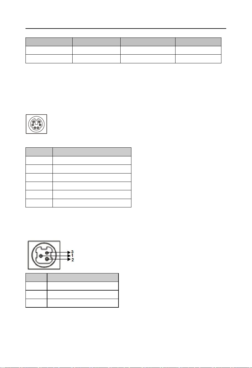
2.3.6 Keyboard and Mouse Port(Ms/Kb)
BIS-6620III/IV provides 1x PS/2 keyboard and mouse port. It is necessary to use PS/2Y
keyboard and mouse line attached randomly to connect to a separate keyboard interface and
mouse interface.
Ms/Kb:
2.3.7 Power Port(DC +12V)
BIS-6620Ⅰ/Ⅱ with single-supply+12V input.
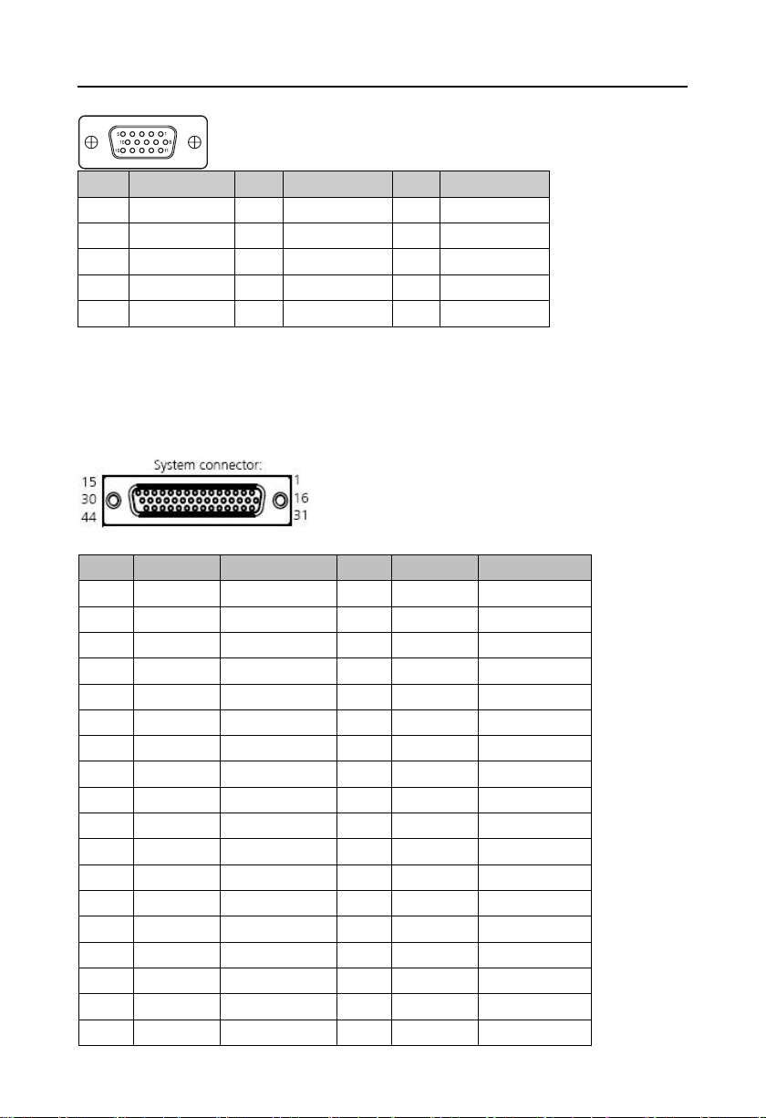
2.4 BIS-6620III Expansion Board Interface
2.4.1 VGA port(VGA)
Standard 15Pin VGA port,can connect to all standard VGA interfaces display.
7
BIS-6620 Based on Menlow Platform Mini PC
Pin
Signal Name
Pin
Signal Name
Pin
Signal Name
1
Red6GND11NC
2
Green7GND12SDA
3
Blue8GND
13
HSYNC
4NC9
+5V14VSYNC
5
GND10GND15SLC
Pin
Controller
Definition
Pin
Controller
Definition
1
A-1
DCD3
23
C-3
TXD5
2
A-2
RXD3
24
C-4
DTR5
3
A-3
TXD3
25
C-5
GND
4
A-4
DTR3
26
C-6
DSR5
5
A-5
GND
27
C-7
RTS5
6
A-6
DSR3
28
C-8
CTS5
7
A-7
RTS3
29
C-9
RI5
8
A-8
CTS3
30NCGND
9
A-9
RI331D-1
DCD6
10NCGND
32
D-2
RXD6
11
B-1
DCD4
33
D-3
TXD6
12
B-2
RXD4
34
D-4
DTR6
13
B-3
TXD4
35
D-5
GND
14
B-4
DTR4
36
D-6
DSR6
15
B-5
GND
37
D-7
RTS6
16
B-6
DSR4
38
D-8
CTS6
17
B-7
RTS4
39
D-9
RI6
18
B-8
CTS4
40NCGND
2.4.2 Serial Port(COM)
Expansion board provides 1xDB44 1 to 4 COM port,When using, it is necessary to use the
1 to 4 COM line in the fittings box to transfer to the standard DB9 COM port.
8
BIS-6620 Based on Menlow Platform Mini PC
19
B-9
RI441NC
20NCGND42NC
21
C-1
DCD543NC
22
C-2
RXD544NC
Signal Name
Pin
Signal Name
D2+
12GND
D2-
34D1+
GND
56D1-
D0+
78GND
D0-
910CK+
GND
1112CK-
NC
1314NC
DDC CLK
1516DDC DATA
GND
1718+5V
HP DET
1920GND
GND
2122GND
GND
2324GND
GND
2526GND
GND
2728GND
GND
2930GND
GND
31
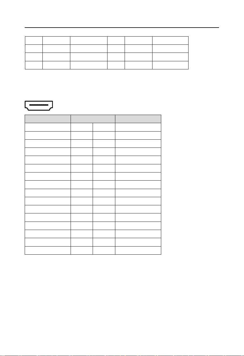
2.5 BIS-6620IV Expansion Board Interface
2.5.1 HDMI Port(HDMI)
BIS-6620IV provide 1xHDMI port to connect LCD.
2.5.2 SATA Port(SATA)
transmission rate up to 300MB/s.
AFC-341V and AFC-450H adaptor plates are both provide with 1x7+15Pin Serial ATA port,
9
BIS-6620 Based on Menlow Platform Mini PC
Pin
Signal Name
Pin
Signal Name
1
GND
P2
+3.3V
2
TX+
P3
GND
3
TX-P4GND
4
GNDP5NC
5
RX-P6NC
6
RX+P7NC
7
GNDP8NC
P1
+3.3V
P9
NC
10

Chapter
Three
Hardware
Installa
tion

BIS-6620 Based on Menlow Platform Mini PC
11
Chapter Three Hardware Installation
Before installing computer accessories
Following the following security principles can help prevent potential damage to
your computer and help ensure your personal safety.
1:Make sure your computer is not connected to the power supply.
2 : When contacting IC components (such as RAM, etc.), it is better to wear
anti-static bracelets/gloves.
3:Prepare a small cross screwdriver
3.1 Remove Host Cover
1:Use cross screwdriver to unscrew four screws at the bottom of BIS-6620.
2:Grasp both sides of the main cover by hand, lift it up and remove it.
3.2 Hardware Installation
3.2.1 Memory module replacement/installation
BIS-6620 provide 1x 200Pin DDRⅡ SO-DIMM slot , support DDRⅡ400 / 533MHz,
memory up to 1GB. You can choose from 512MB to 1GB conforming memory strips for
installation.,detailed installation should follow the following steps:
 Loading...