

Norco BIS-6592LC User Manual

Thanks for purchasing our computer for LED display system. We attach great importance to the
manual.The more you understand the manual, the more easily you can install it The
instructions in this manual will facilitate your operation of this LED control system
About this manual
This manual contains a general description of BIS-6592LC and the detailed description of its
functions, features, installation and dismounting instructions, BIOS settings, etc., which helps
you to use this product in a right way.
Symbols
This represents the important information to facilitate your use of this product
This symbol to make you notice that it may cause damage or data loss, and tell you how
to advoid such problems.
This symbol indicates that operation may lead to property loss or bodily injury.
Safety Information
This information can help you to use the product safely.Please strickly follow the labeled
warnings and intructions given.We focus on the customer’s safety. The products we develop
base on safety and availability.However, Power lines and other parts that the motherboard
contained may cause a potential risk in the case of improper installing.They may result in bodily
injury or property loss. Please follow the manual step by step to avoid these hazards.
Validity
The ceaseless upgrading of computer structure, components and accessories guarantees the
superiority and superb quality of the computer, therefore, you may find some features of your
NORCO computers is not in accord with the description in this manual. NORCO reserves the
right to make changes, without prior notice,
Disclaimer
Except for the accessories attached to the product as specified herein, what is contained in this
user manual does not represent the commitments of NORCO Compay. NORCO Company
reverves the right to revise this User Manual,without prior notice,and will not be held liable for
any direct ,indirect,intended or unintended losses and/or hidden dangers due to installation or
improper operation.

Content
Chapter 1 Product Introduction.............................................................................1
1.1 Overview...........................................................................................................................1
1.2 Product Specification........................................................................................................1
1.3 Product Indicator Diagram................................................................................................2
Chapter 2 Motherboard Description......................................................................4
2.1 Interface Location and Dimension...................................................................................4
2.2 Installation Steps...............................................................................................................4
2.3 Install CPU........................................................................................................................5
2.4 Install SO-DIMM...............................................................................................................6
2.5 Jumper Settings................................................................................................................6
2.5.1 CMOS Clear/Hold Jumper Setting (JCC) ........................................................6
2.5.2 COM2 Jumper Setting(J7, J8, J9) ....................................................................7
2.5.3 LVDS Rated Voltage Select Jumper(J2)...........................................................8
2.6 Interfaces Description.......................................................................................................9
2.6.1 SATA and SATA Power Interface(SATA1, SATA2, J6) .....................................9
2.6.2 CF Card Socket(Compact Flash)....................................................................10
2.6.3 Serial Ports(COM1, COM2, COM3-6) ............................................................11
2.6.4 Display Interfaces(VGA, TV-OUT, HDMI, DVI, LVDS) ...................................13
2.6.5 LVDS Backlight Control and Voltage Select(J1).............................................15
2.6.6 USB & LAN Ports(USB_LAN1,USB_LAN2,USB_1,USB_2) .........................16
2.6.7 Keyboard & Mouse Connector(PS/2) .............................................................18
2.6.8 Infrared Transmission Interface(IRDA)...........................................................19
2.6.9 General Purpose Input/Output(GPIO) ............................................................19
2.6.10 Power Interface (PWR)......................................................................................20
2.6.11 FAN Connector(GMCHFAN, CPUFAN) ........................................................21
2.6.12 Audio Interface(AUDIO).....................................................................................22
2.6.13 Front Panel Connector(JFP) .........................................................................22
2.6.14 SO-DIMM(DIMM1, DIMM2) ..........................................................................24
2.6.15 PCIE Slot............................................................................................................24
2.6.16 Mini PCIE(MINI_PCIE1, MINI_PCIE2,J3,J4) ...............................................24
Chapter 3 Computer Installation and Use.............................................................25

3.1 Install Computer Peripheral Accessories.......................................................................25
3.1.1 DVI Interface Connection.....................................................................................25
3.1.2 COM Device Connection.....................................................................................25
3.1.3 PS/2 Keyboard and Mouse Connection..............................................................25
3.1.4 Power Cable Connection.....................................................................................26
3.2 Install Computer Software..............................................................................................26
3.2.1 Install Operating System.............................................................................................26
3.2.2 Install Driver..........................................................................................................26
3.3 BIS-6592LC BIOS Setup................................................................................................26
AMI BIOS Flash....................................................................................................................26
AMI BIOS Description...........................................................................................................27
BIOS Settings........................................................................................................................27
3.1 Main Menu......................................................................................................................28
3.2 Advanced Menu..............................................................................................................29
3.2.1 CPU Configuration...............................................................................................30
3.2.2 IDE Configuration.................................................................................................31
3.2.3 Supper IO Configuration......................................................................................33
3.2.4 Hardware Health Configuration...........................................................................34
3.2.5 ACPI Configuration...............................................................................................35
3.2.6 AHCI Configuration..............................................................................................37
3.2.7 ASF Configuration................................................................................................39
3.2.8 ME BIOS Extension Configuration......................................................................39
3.2.9 Intel VT-d Configuration.......................................................................................41
3.2.10 MPS Configuration.............................................................................................42
3.2.11 APM Configuration..............................................................................................42
3.2.12 USB Configuration.............................................................................................44
3.2.13 On board LAN Option ROM...............................................................................46
3.3 PCI PnP Menu................................................................................................................47
3.4 Boot Menu.......................................................................................................................49
3.4.1 Boot Setting Configuration...................................................................................50
3.4.2 Boot Device Priority..............................................................................................52
3.4.3 Hard Disk Drives..................................................................................................53
3.5 Security Menu.................................................................................................................54

3.6 Chipset Menu..................................................................................................................55
3.6.1 North Bridge Configuration..................................................................................56
3.6.2 South Bridge Chipset Configuration....................................................................58
3.7 Exit Menu........................................................................................................................60
Chapter 4 Install & Replace Components.............................................................62
4.1 Remove Computer Cover...............................................................................................63
4.2 Replace DIMM................................................................................................................64
4.3 Install CF Card................................................................................................................64
4.4 Mounting Bracket............................................................................................................65
Appendix............................................................................................................66
Appendix 1: Driver Installation..............................................................................................66
Appendix 2: Watchdog Programming Guide.......................................................................67
Appendix 3: GPIO Instruction...............................................................................................69
Appendix 4: Glossary............................................................................................................70

Packing List
Thanks for purchasing NORCO products. Please check your
packagecarefully according to the checklist below. If you find any
components lost or damaged, please contact your retailer.
■ BIS-6592LC
■ User Manual
■Drive Disk
■DVI Cable
■Power Adaptor
■Wall-Mount Kit
■Screw
1pcs
1pcs
1pcs
1pcs
1set
1set
1bag

Chapter 1 Product Introduction
BIS-6592LC LED Screen Control Hardware Platform supporting 1080P HD Display
1
Chapter 1 Product Introduction
1.1 Overview
BIS-6592LC is Intel GM45 based fanless solution specially designed for digital signage
applications. “ICEFIN” enclosure, compact and slim, utilizing Intel Penryn/Core 2 Duo
/Celercon M processors. It offers high performance with industrial-grade reliability. 2x DDR3
800/1066MHz SO-DIMM, onboard memory up to 8GB. DVI, VGA and HDMI display output.
System also features rich I/O: 1x COM, 4x USB2.0, 1xCF, 1x Mini PCIe SSD, 1x 2.5” SATA,
2xLAN, 1x KB, 1x MS, 1x Mic in, 1x Line out, 1x Mini PCIe and 1x PCI LED control card reserve
location. With flexible expansion and multiple display, BIS-6592LC is widely used in such
applications as advertising, LCD Large Screen, Rail Transportation, self-service terminals,
Information Control, Video Surveillance, etc.
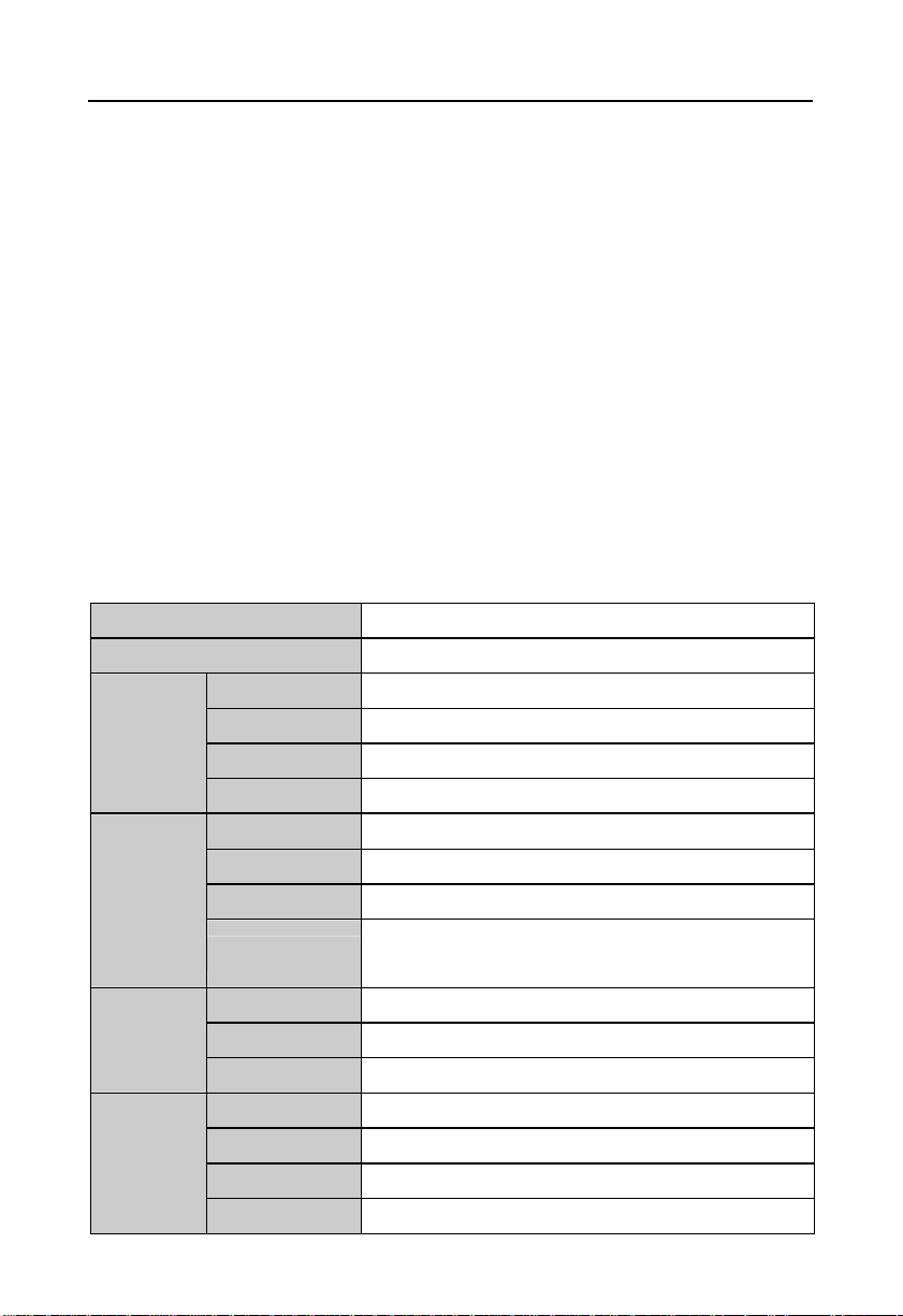
1.2 Product Specification
Model BIS-6592LC
Platform Intel
Color Black
Chassis
Motherboard
Storage
System
Features
Dimension 355mm×194mm×54.5mm(W×D×H)
Structure ICEFIN fanless enclosure
Material Aluminium alloy
Model MITX- 6892
Processor Socket P Intel Penryn/Core 2 Duo/Celeron M
Chipset Intel GM45+ICH9BM
Memory
CF 1x CF
SSD 1x Mini PCIe SSD(optional)
HDD 1x 2.5"SATA
Network Intel 82567LM/82574L,10/100/1000Mbps,2x LAN
USB 4x USB2.0
Serial Port 1x RS232(DB9)
Display 1x VGA,1x DVI-D,1x HDMI
2x 204Pin SO-DIMM slots support DDR3
667/800/1066MHz, RAM upto 8GB
BIS-6592LC LED Screen Control Hardware Platform supporting 1080P HD Display
2
3
4
5
8 9 7
13
Cooling System 1x CPU FAN
Audio 1x Mic-in,1x Line-out
Expansions 1x PCI LED Control card reserve location
System LED N/A
System Control Power ON/OFF Switch
PS/2 1x KB,1x MS
Power Power Supply DC +12V power adaptor
Mounting Desktop or Wall Mount
Operating Temp
Storage Temp
Reliability
Relative Humidity
Operating
Vibration
EMC CE/FCC Class B
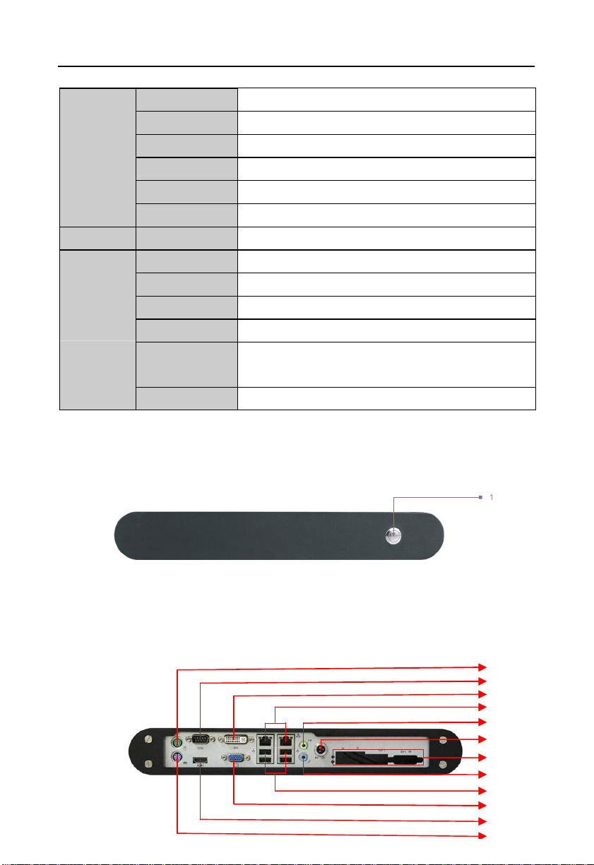
1.3 Product Indicator Diagram
1:BIS-6592LC Front View
0℃~55℃
-40℃~80℃
5%~95% relative humidity, non-condensing
0.5g rms/5~500Hz/random operating
1. Power Button
2:BIS-6592LC Rear View
2
6
10
11
12

BIS-6592LC LED Screen Control Hardware Platform supporting 1080P HD Display
3
2:Mouse
4:DVI
6: SPEAKER-OUT
8:LED Controller
10:4x USB 2.0
12:HDMI
3: COM
5:2x LAN
7:DC 12V
9: MIC-IN
11: VGA
13:Keyboard

Chapter 2 Motherboard Description

4
BIS-6592LC LED Screen Control Hardware Platform supporting 1080PHD Display
Chapter 2 Motherboard Description
2.1 Interfaces Location & Dimension
The following picture shows the front panel interfaces location and the dimension of the board
MITX-6892 (board rear with 1 x SO-DIMM slot, 1x CF card socket and 1x MINI-PCIE slot.).
Please pay attention to the installation procedures. Improper installation of any components
will lead to system malfunction.
Note: Before installation, we must put on the anti-static gloves, in case that the static
electricity causes damage to the motherboard.
MITX-6892 Dimension
2.2 Installation Steps
Please follow the steps below to assemble your computer
1. Refer to the manual and setup all the jumpers of BIS-6592LC.
5
BIS-6592LC LED Screen Control Hardware Platform supporting 1080PHD Display
2. Install CPU
3. Install Motherboard
4. Intall other expansion cards
5. Connect all signal cable, power cable, panel control cable and power supply
6. Start the computer and complete the BIOS setting
Key components of this motherboard are integrated circuit, and these components
will be easily damaged by electrostatic influence. So, before installing the
motherboard, you should always keep the following precautions in mind:
1. Hold the board by edges, don’t touch any components or plug and socket pins
2.Wear anti-static gloves/wrist strap while touching the integrated circuit components, such as
CPU, RAM, etc.
3.Put those unused or uninstalled components in static shielding bags or trays
4.Please first check the power switch is off before connecting the power plug
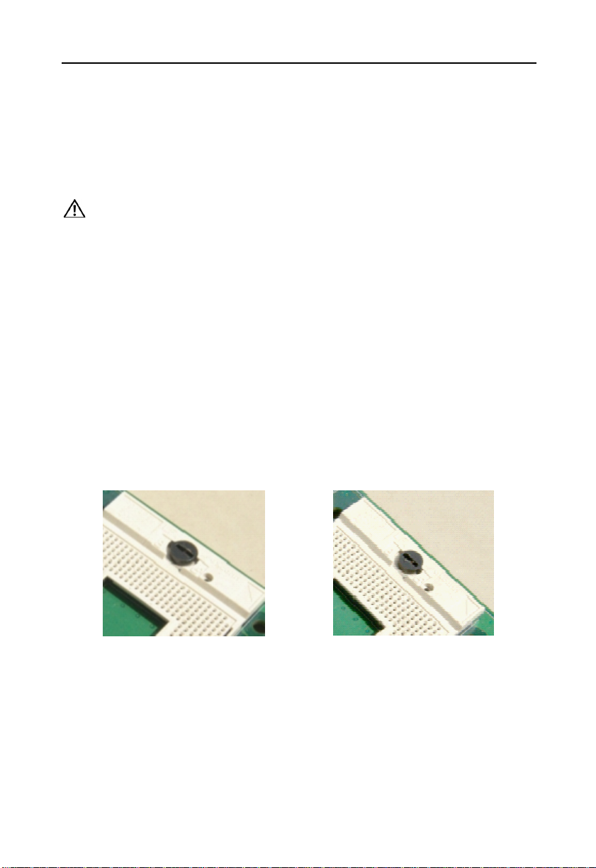
2.3 Install CPU
Please follow the steps below to install CPU:
1. Use screwdriver to unscrew the CPU, making CPU “Locked” to “ Unlock”, illustrated as
below:
2. Hold the CPU by both sides, then align the CPU Pin1 (a golden triangle mark) with the notch
on CPU socket and insert the CPU into the socket. Check the connection and then lock the
CPU by using the screwdriver.
Note: Please make sure the CPU you used matches the motherboard. After system boots up,
BIOS will auto detect the CPU type and its frequency. BIOS settings will not allow users to
adjust the CPU frequency doubling. To ensure the system works stably, we don’t recommend
you to make the CPU overlocking. Right now, most Intel CPU frequency doubling is factory
default as unchangeable.

6
BIS-6592LC LED Screen Control Hardware Platform supporting 1080PHD Display
2.4 Install SO-DIMM
Board with 2x DDRIII SO-DIMM slots. Pls keep following two points in mind to install
SO-DIMM:
1. First, please algin the notch of the memory bank with the notch on the socket and press the
memory bank slowly into the socket.
2. Please choose the proper memory bank that matches your motherboard
2.5 Jumper Settings
Please refer to following instructions to do jumper settings before installing your hardware
devices.
Remark: How to identify the PIN1 of all jumpers and interfaces: Please observe the word mark
on the side of the plug socket, which will be a “1” or bold line or triangular symbol; And please
look at the back of PCB, each with a square shape will be the PIN 1; and all the jumpers’ PIN1
have a white arrow on the side.
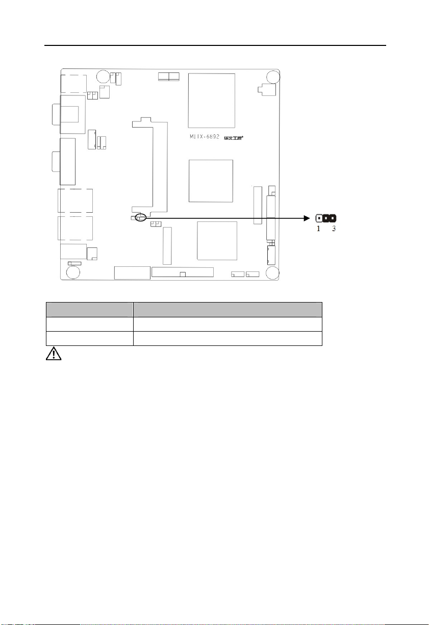
2.5.1 CMOS Clear/Hold Jumper Setting(JCC)
CMOS is powered by the onboard button cell. Clear CMOS will lead to permanent elimination
of previous system settings and back to the original system setting (factory default).
Steps:(1)Turn off the computer and disconnect the power supply
(2)Use Jumper Cap JCC Pin1-2 short for 5~6 sec. Then restore the default setting
with Pin2-3 connected
(3)Turn on the computer, then press “DEL” key to enter BIOS setting and reload
optimal defaults.
(4)Save and Exit
7
BIS-6592LC LED Screen Control Hardware Platform supporting 1080PHD Display
Setting JCC
1-2 BIOS back to intialization (factory dafault)
2-3 Normal Status, System default
Do not clear CMOS when the computor is power on, otherwise, it will cause
damage to the motherboard!
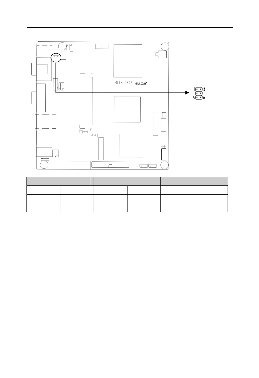
2.5.2 COM2 Jumper Setting(J7,J8,J9)
J7, J8,J9 jumpers are used to configure COM2 transmission mode. COM2 supports RS
232/RS 422/RS 485. System default RS 232 .
8
BIS-6592LC LED Screen Control Hardware Platform supporting 1080PHD Display
COM2 RS232(Default)
J7 3-5 4-6 J7 1-3 2-4 J7 1-3 2-4
J8 3-5 4-6 J8 1-3 2-4 J8 1-3 2-4
J9 1-2 J9 3-4 J9 5-6 7-8
COM2 RS422 COM2 RS485
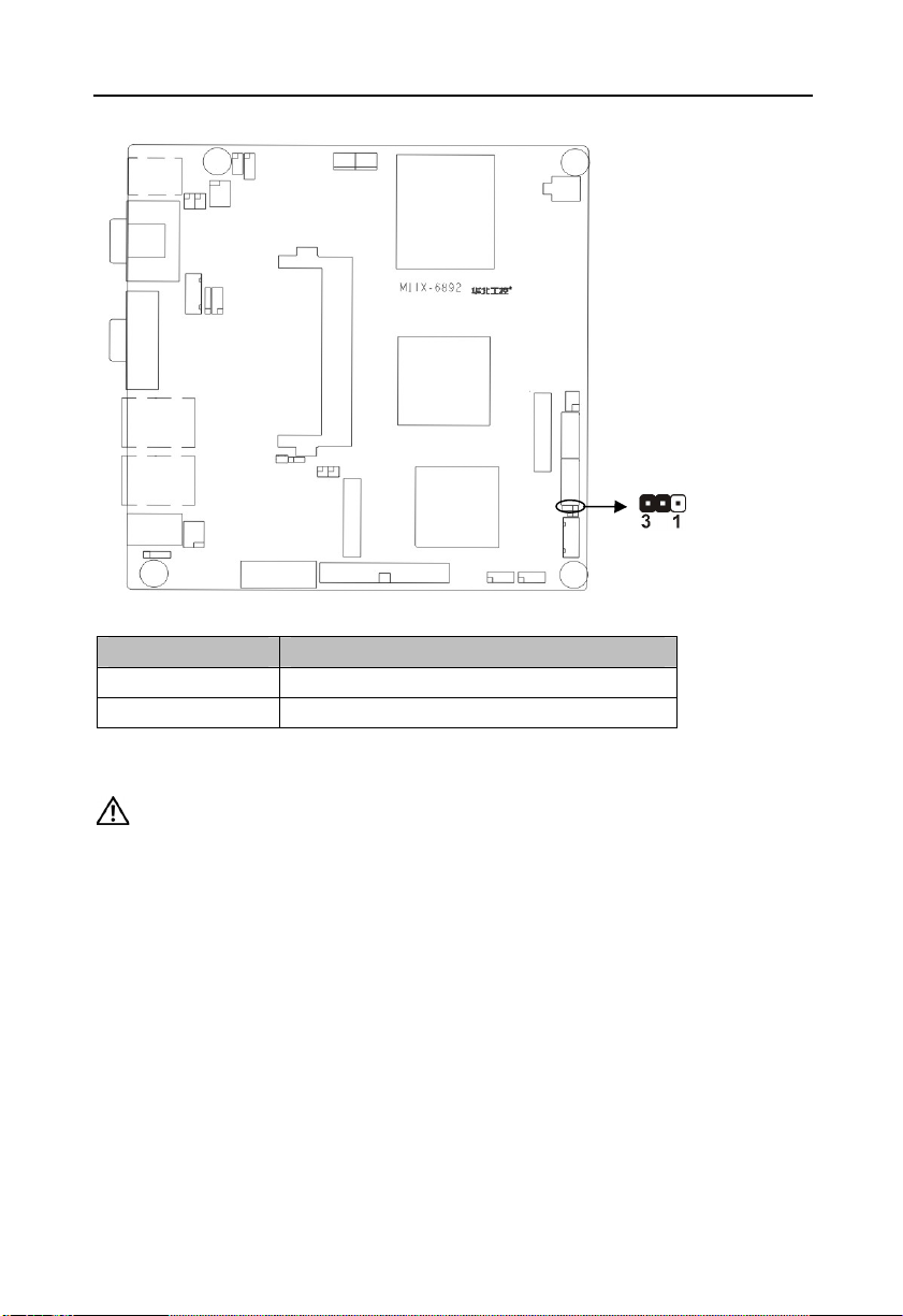
2.5.3 LVDS Rated Voltage Select Jumper(J2)
Before using the LVDS, please first check the rated operating voltage. J2 is selected by LVDS
rated voltage.
9
BIS-6592LC LED Screen Control Hardware Platform supporting 1080PHD Display
Setting J2
1-2 VCC
2-3 VCC3
2.6 Interfaces Description
Please read the following instructions carefully before you connecting the external
connectors in case of any damage caused to the motherboard.
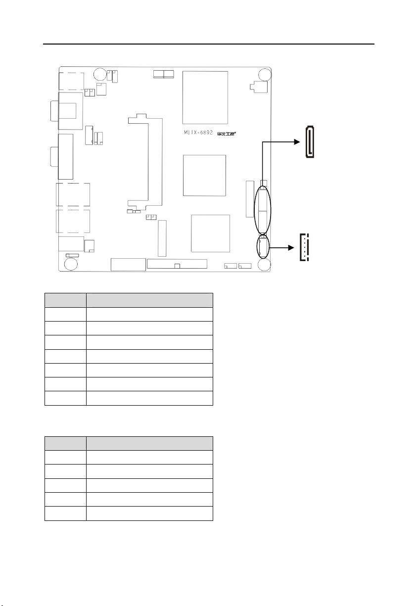
2.6.1 SATA & SATA Power Interface(SATA1, SATA2, J6)
Board provides 2x SATA ports. When using these interfaces, HDD is power-up through the
SATA power interface with an adapter cable
10
BIS-6592LC LED Screen Control Hardware Platform supporting 1080PHD Display
SATA:
Pin Signal Name
1 GND
2 TX+
3 TX4 GND
5 RX6 RX+
7 GND
J6( SATA Power Interface):
Pin Signal Name
1 +12V
2 GND
3 VCC
4 GND
5 VCC3
2.6.2 CF Card Socket(Compact Flash)
Board rear panel with one 50Pin CF Card Socket supports DMA mode.
11
BIS-6592LC LED Screen Control Hardware Platform supporting 1080PHD Display
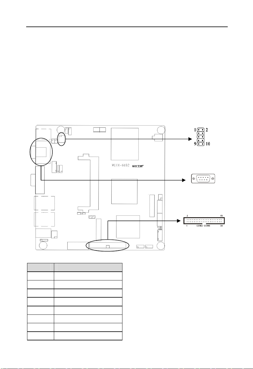
2.6.3 Serial Ports(COM1,COM2, COM3-6)
Board provides 6x serial ports. COM1 and COM2 adopt IO chip. COM3-6 adopt F81216AD.
Chip. COM1 is the DB9 interface. COM2 is the 2x 5Pin interface. COM2 needs to be
converted into standard DB9 interface to connect external devices. Users can open or close
the serial ports and select its IRQ and IO address under BIOS settings.
COM1&COM2 support RS232. COM2 also supports RS422/485. Users can select COM2
transmission mode by COM2 jumper setting. Details pls refer to Chapter 2-2.5.2 “ COM2
Jumper Setting” .
COM1:
Pin Signal Name
1 DCD
2 RXD
3 TXD
4 DTR
5 GND
6 DSR
7 RTS
8 CTS

12
BIS-6592LC LED Screen Control Hardware Platform supporting 1080PHD Display
9 RI
COM2:
Signal Name Pin Signal Name
DCD 1 2 DSR
SIN 3 4 RTS
SOUT 5 6 CTS
DTR 7 8 RI
GND 9 10 GND
COM2 configured as RS232/RS422/RS485, Pins defined as below:
RS485 RS422 RS232 Pin RS232 RS422 RS485
DATA- TX- DCD 1 2 RXD TX+ DATA+
NC RX+ TXD 3 4 DTR RX- NC
GND GND GND 5 6 DSR NC NC
NC NC RTS 7 8 CTS NC NC
NC NC RI 9
COM3-6:
Signal Name Pin Signal Name
HDCD#3 1 2 HDSR#3
HRXD3 3 4 HRTS#3
HTXD3 5 6 HCTS#3
HDTR#3 7 8 HRI#3
GND 9 10 GND
HDCD#4 11 12 HDSR#4
HRXD4 13 14 HRTS#4
HTXD4 15 16 HCTS#4
HDTR#4 17 18 HRI#4
GND 19 20 GND
HDCD#5 21 22 HDSR#5
HRXD5 23 24 HRTS#5
HTXD5 25 26 HCTS#5
HDTR#5 27 28 HRI#5
GND 29 30 GND
HDCD#6 31 32 HDSR#3
13
BIS-6592LC LED Screen Control Hardware Platform supporting 1080PHD Display
HRXD6 33 34 HRTS#6
HTXD6 35 36 HCTS#6
HDTR#6 37 38 HRI#6
GND 39 40 GND
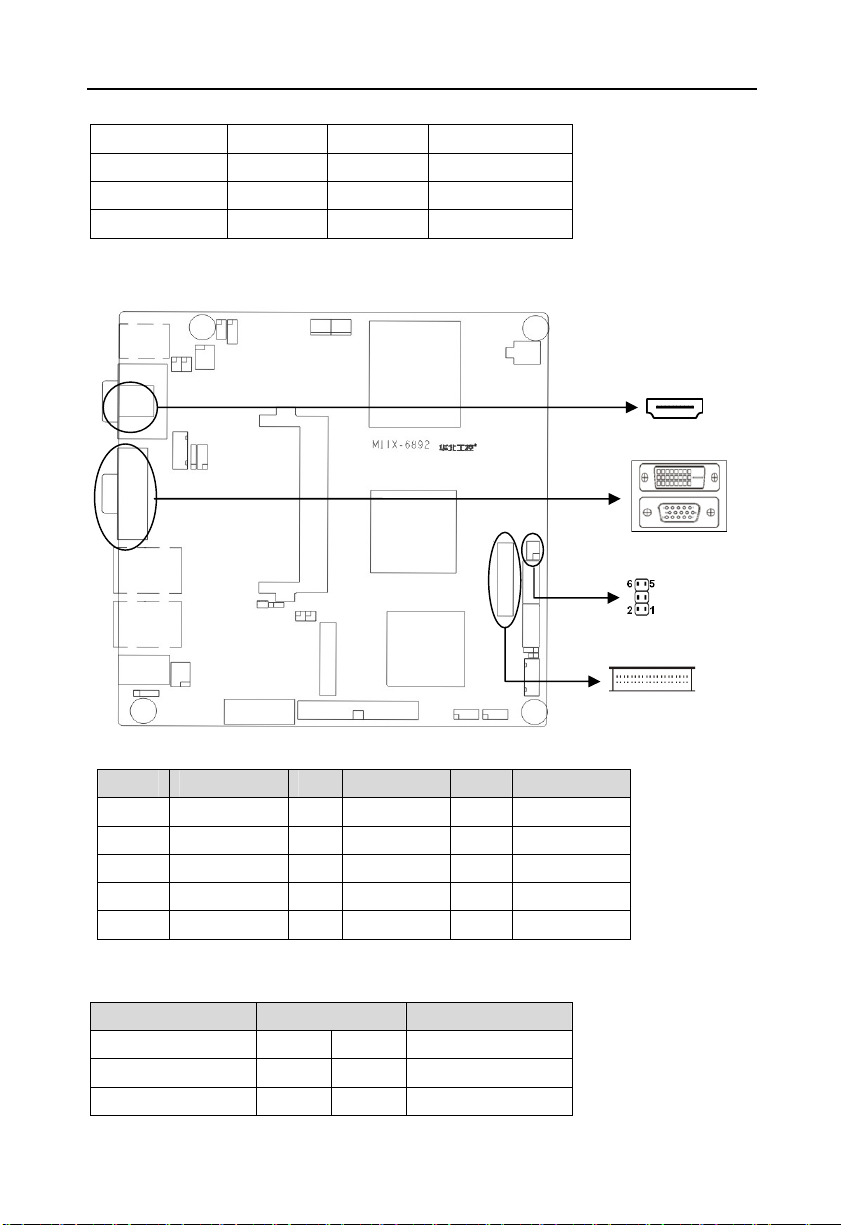
2.6.4 Display Interfaces(VGA, TV-OUT, HDMI, DVI, LVDS)
VGA:
Pin Signal Name Pin Signal Name Pin Signal Name
1 RED 6 GND 11 NC
2 GREEN 7 GND 12 SDA_R
3 BLUE 8 GND 13 HS_R
4 NC 9 VCC 14 VS_R
5 GND 10 GND 15 SCL_R
TV-OUT:
Signal Name Pin Signal Name
TV-DACA-OUT 1 2 GND
TV-DACB-OUT 3 4 GND
TV-DACC-OUT 5 6 GND
14
BIS-6592LC LED Screen Control Hardware Platform supporting 1080PHD Display
HDMI:
Signal Name Pin Signal Name
D2+ 1 2
D2- 3 4
D1 Shield
CK Shield
CE Remote 13 14
DDC CLK
SHELL11
5 6
D0+ 7 8
D0- 9 10
11 12
15 16 DDC DATA
17 18 +5V
GND
HP DET 19 20
21 22
SHELL1
SHELL3
SHELL5
SHELL7
SHELL9
23 24
25 26
27 28
29 30
31
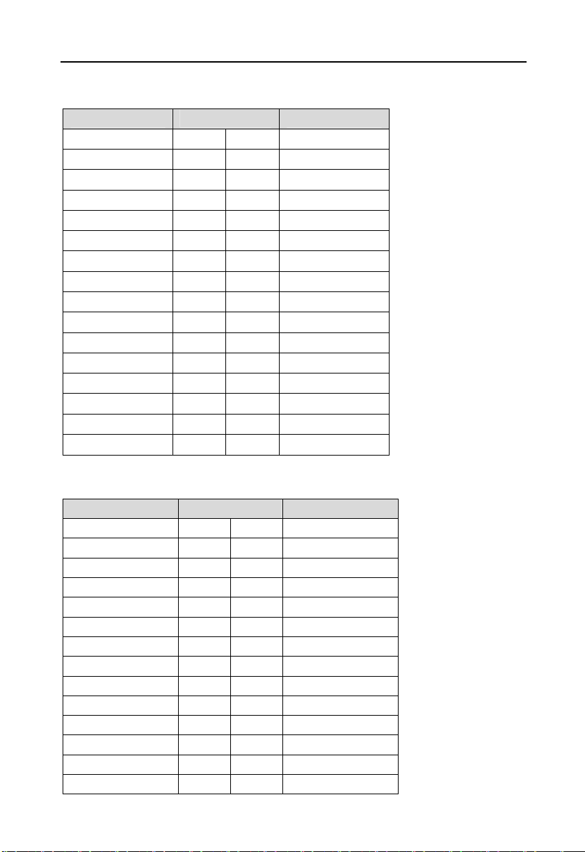
DVI(recommend to use 18bit DVI cable ):
Signal Name Pin Signal Name
TDC2# 1 2 TDC2
GND 3 4 NC
NC 5 6 SC-DDC
SD-DDC 7 8 NC
TDC1# 9 10 TDC1
GND 11 12 NC
NC 13 14 VCC
GND 15 16 HP-DETECT
TDC0# 17 18 TDC0
GND 19 20 NC
NC 21 22 GND
TLC 23 24 TLC#
GND 25 26 GND
NC 27 28 NC
D2 Shield
D0 Shield
SHELL10
D1+
D1-
CK+
CK-
NC
SHELL0
SHELL2
SHELL4
SHELL6
SHELL8

15
BIS-6592LC LED Screen Control Hardware Platform supporting 1080PHD Display
LVDS:
Signal Name Pin Signal Name
VDD_PANEL 1 2 VDD_PANEL
GND 3 4 GND
LVDSA_DATA0# 5 6 LVDSB_DATA0#
LVDSA_DATA0 7 8 LVDSB_DATA0
GND 9 10 GND
LVDSA_DATA1# 11 12 LVDSB_DATA1#
LVDSA_DATA1 13 14 LVDSB_DATA1
GND 15 16 GND
LVDSA_DATA2# 17 18 LVDSB_DATA2#
LVDSA_DATA2 19 20 LVDSB_DATA2
GND 21 22 GND
LVDSA_CLK# 23 24 LVDSB_CLK#
LVDSA_CLK 25 26 LVDSB_CLK
GND 27 28 GND
LVDS_DDV_DATA 29 30 LVDS_DDC_CLK
GND 31 32 GND
LVDSA_DATA3# 33 34 LVDSB_DATA3#
LVDSA_DATA3 35 36 LVDSB_DATA3
VCC3 37 38 GND
NC 39 40 NC
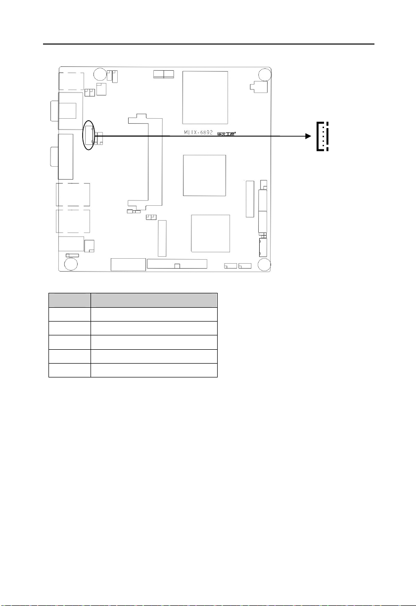
2.6.5 LVDS Backlight Control and Voltage Select(J1)
J1 is used to adjust LVDS devices backlight brightness.
16
BIS-6592LC LED Screen Control Hardware Platform supporting 1080PHD Display
J1:
Pin Signal Name
1 +12V
2 L_BKLTEN
3 GND
4 L_BKLTCTL
5 VCC
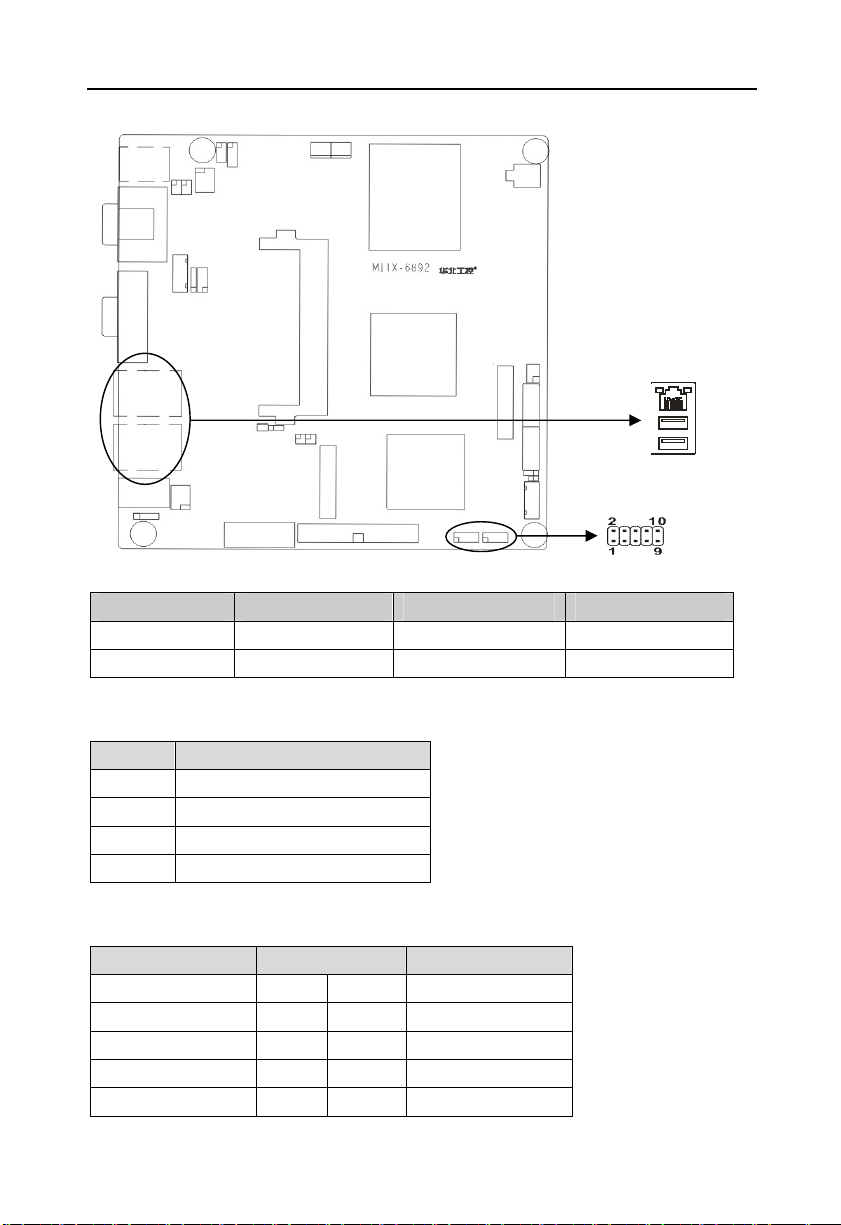
2.6.6 USB & LAN Ports(USB_LAN1,USB_LAN2,USB_1,USB_2)
Board provides 8x USB2.0 and 2x RJ-45 network interfaces. USB_LAN1 and USB_LAN2 is
the combination of 2x standard USB2.0 and 1x 10/100/1000Mb RJ45 network interface. The
2x 5Pin signal of USB_1 and USB_2 is connected to standard USB socket with an adapter
cable, upto 4x standard USB sockets. Both sides of the RJ-45 LAN port have a LED lamp. The
yellow one indicates data transmission status. The green one indicates the network link status.
17
BIS-6592LC LED Screen Control Hardware Platform supporting 1080PHD Display
RJ45 PORT LED Status:
LILED(Green) Function ACTLED(Yellow) Function
On Effective Link Flash Data transferrring
Off Ineffective Link /Off
Standard USB Ports:
Pin Signal Name
1 +5V
2 USB DATA3 USB DATA+
4 GND
USB_1, USB_2:
Signal Name Pin Signal Name
VCC 1 2 GND
USB DATA- 3 4 GND
USB DATA+ 5 6 USB DATA+
GND 7 8 USB DATA-
GND 9 10 VCC
Off No Data
18
BIS-6592LC LED Screen Control Hardware Platform supporting 1080PHD Display
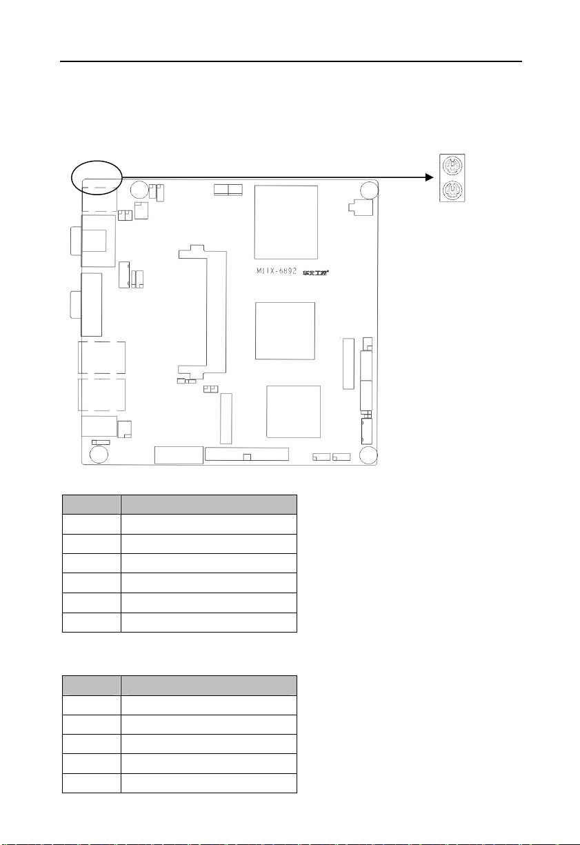
2.6.7 Keyboard & Mouse Connector(PS/2)
PS/2 is the keyboard and mouse interface on the rear panel. Users can use PS/2 to connect its
keyboard connector and mouse connector.( The green interface is the mouse connector, the
purple one is the keyboard connector)
Mouse Define:
Pin Signal Name
7 +5V
8 GND
9 NC
10 MS_DATA
11 MS_CLK
12 NC
Keyboard Define:
Pin Signal Name
1 +5V
2 GND
3 NC
4 KB_DATA
5 KB_CLK
 Loading...