

Norco BIS-6540HD User Manual
BIS-6540HD
Full HD Compact Signage Platform
USER' Manual V1.0

Shenzhen NORCO Intelligent Technology Co., Ltd.:0755-27331166
Beijing:010-82671166
Shanghai:021-61212088
Nanjing: 025-58015489
Chengdu:028-85259319
Shenyang:024-23960846
Xi’an:029-88338386
Nanjing: 025-58015489
Wuhan:027-87858983
Tianjin:022-23727100
Singapore:65-68530809
Netherlands:31-040-2668554
Web:www.norco.cn
BIS-6540HD
Full HD Compact Signage Platform
USER' Manual V1.0

Place/Data: HONG KONG/2009
Shenzhen NORCO Intelligent Technology Co.,Ltd.
Shenzhen NORCO Intelligent Technology Co.,Ltd.
BIS-6540HD Full HD Compact Signage Platform
Data: 2009
Trade Name:Shenzhen NORCO Intelligent Technology Co.,Ltd.
Model Name:BIS-6540HD
Responsible Party:Shenzhen NORCO Intelligent Technology Co.,Ltd.
Equipment Classification:FCC Class B Subassembly
Type of Product:BIS-6540HD
Full HD Compact Signage Platform
Manufacturer:Shenzhen NORCO Intelligent Technology Co.,Ltd.

Copyright
With the exception of showing the accessories of product configuration,
this manual do not create any commitment of our company. We retained the
rights to change it without prior notice. We will not be responsible for any
installation, the result of improper use of direct, indirect, intentional or
unintentional damage or hidden dangers.
Before buying products, please learn about product performance from
the seller to see if it is in line with your needs. NORCO is a registered
trademark of Shenzhen NORCO Intelligent Technology CO.,Ltd. Other
trademarks involved in this manual, their ownership are owned by its
respective owners. The contents of this manual are protected by copyright
law. All rights are strictly reserved. Any form of unauthorized reproduction
including but not limited to carbon copy, facsimile transmission and
electronic copy or email should be destroyed immediately.

Safety Instructions
1:Please read these safety instructions carefully。
2:Before inserting or removing expansion cards, re-assembling or
re-configuring, disconnect the computer and peripherals from their power
sources to prevent electric shock or system board damage。
3:Before attempting to move the product, the system must be
powered-down and the power cord must be disconnected from the power
source。
4:Before connecting or disconnecting any signal line, first turn off all power
resources and disconnect the power cord from power source。
5:To help avoid possible damage to system boards, wait at least 30
seconds after turning off the computer before re-turning on the computer。
6:Use cross head screwdriver to operate. A magnetic screwdriver is
recommended (magnet to collect screws).Do not leave any tools or
components inside the chassis.
7:Assure abundant cooling and streamline ventilation。
8:If anything unexpected exists during Equipment used, please contact the
professionals.

Contents
Chapter General Information....................................................................................... 1
1.1 Introduction ................................................................................................................. 1
1.2 Features...................................................................................................................... 1
1.3 Hardware Specification............................................................................................... 2
1.4 Dimensions Diagram .................................................................................................. 4
Chapter2 Hardware Functionality.............................................................................. 5
2.1 External I/O Connectors ............................................................................................. 5
2.2 Internal Structure ........................................................................................................6
2.3 Back Panel I/O Connectors ........................................................................................ 7
2.3.1 Serial Port(COM1,COM2) ................................................................................... 7
2.3.2 USB Port(USB) ................................................................................................... 7
2.3.3 Ethernet connector(LAN) .................................................................................... 8
2.3.4 PS2 Keyboard/Mouse Connector(MS,KB) ....................................................... 9
2.3.5 Audio Jack(LINE-OUT,MIC-IN) ........................................................................ 9
2.3.6 VGA Connector(VGA)....................................................................................... 10
2.3.7 DVI Connector(DVI).......................................................................................... 10
2.3.8 Power input connector(POWER)...................................................................... 11
2.4 Inside connectors...................................................................................................... 12
2.4.1 IDE Connector(IDE1) ........................................................................................ 12
2.4.2 SATA Connector&SATA Power Connector(SATA0,SATA1,S_PWR)............ 13
2.4.3 Parallel Por(LPT) .............................................................................................. 15
2.4.4 Onboard USB Ports(USB12,USB34,USB56) .............................................. 16
2.4.5 Expandsion Serial Ports(COM3-6,COM7-10) ................................................ 17
2.4.6 IRDA interface(IRDA)........................................................................................ 19
2.4.7 GPIO(J10) ......................................................................................................... 19
2.4.8 ATX PowerSupply Connector(ATX)................................................................... 21
2.4.9 Front Panel connector
(J4) ................................................................................ 22
Chapter3 Hardware Installation................................................................................ 24

3.1 Setting Jumpers........................................................................................................ 24
3.1.1 Clear CMOS(JCC) ............................................................................................ 24
3.1.2 COM2 setting(J5,J6,J7) ............................................................................... 25
3.1.3 CF Card Master/Slave Selection(JCF).............................................................. 27
3.2 Installing the DDR SDRAM Memory Module ............................................................ 27
3.3 Installing the 2.5" Hard Disk Drive (HDD) ................................................................. 28
3.4 CF Card Installation .................................................................................................. 29
3.5 Installing Wall-Mount ................................................................................................ 30
3.6 Connecting Power .................................................................................................... 30
Chapter4 BIOS Setup..................................................................................................... 29
4.1 Standard CMOS Setup ............................................................................................. 30
4.2 Advanced BIOS Features ......................................................................................... 33
4.2.1 CPU Feature.......................................................................................................... 33
4.2.2 Removable Device Priority .................................................................................... 35
4.2.3 Hard Disk Boot Priority .......................................................................................... 35
4.2.4 CD-ROM Boot Priority ........................................................................................... 36
4.3 Advanced Chipset Features...................................................................................... 39
4.4 Integrated peripherals............................................................................................... 42
4.4.1 OnChip IDE Device................................................................................................ 43
4.4.2 Onboard Device..................................................................................................... 44
4.4.3 Super IO Device .................................................................................................... 45
4.4.4 F81216D[COM3-COM10] ...................................................................................... 48
4.4.5 USB Device Setting ............................................................................................... 50
4.5 Power Management Setup .......................................................................................51
4.6 PnP/PCI Configurations............................................................................................ 54
4.7 PC Health Status ......................................................................................................55
4.8 Frequency/Voltage Control ....................................................................................... 57
4.9 Load Fail-Safe Defaults ............................................................................................ 57
4.10 Load Optimized Defaults ........................................................................................ 58
4.11 Set Supervisor Password........................................................................................ 59
4.12 Set User Password ................................................................................................. 59
4.13 Save&Exit Setup..................................................................................................... 60

4.14 Exit Without Saving................................................................................................. 61
Appendix.............................................................................................................................. 63
Appendix 1: Driver Installation ........................................................................................ 63
Appendix 2:Watchdog programmer guide.................................................................... 64
Appendix3:GPIO Instruction......................................................................................... 66
Appendix 4: Glossary...................................................................................................... 67

Packing List
Thank you very much for choosing our products. Please check your
package completely as the following item checklist first, if you find any
components lost or damaged, please contact your retailer.
■ BIS-6540HD
■User’s Manual
■Drive Disk
■Power cord
■Power adapter
■Wall-Mount
■Screw
1pcs
1pcs
1pcs
1pcs
1set
1set
9pcs

Chapter 1
General Information

BIS-6540HD
Based on Intel Atom Processor Full HD Compact Signage Platform
1
Chapter1 General Information
1.1 Introduction
BIS-6540HD, a high performance full HD 1080p blu-ray capable Intel N270 Atom
processor based platform. It based on NORCO's signature fanless enclosure-ICE FIN, with
high efficient heatpipe design. It has a built-in ultra low power HD AVC/VC-1/MPEG-2 hardware
decoder, capable of full HD real-time decoding of H.264, VC-1 media contents at up to 40Mbps.
The BIS-6540HD is capable to playback full HD 1080p blu-ray content and uses less than 30%
of the 2.5W Atom N270 CPU. That is over eight times more efficient in term of CPU usage
when playing back the same contents of using an Intel T7300 Core 2 Duo processor. The
power consumption of the complete loaded system when playing blu-ray less than 20W. Using
this compact and easy-to-use network device, the users can control, manage and program the
transmission of the multi-media contents through Ethernet.In the applications that can’t provide
wired connection of ethernet
1.2 Features
●Compact & Robust Form Factor
It based on NORCO’s signature fanless enclosure-ICE FIN, with high efficient heatpipe
design.The small foot-print and low-profile case design of BIS-6550 series was designed to
facilitate different types of mounting and installation.
●Onboard Intel Atom Processor
Onboard low-consume 、 high performance Intel
®
Atom N270 1.6G processor, Power
consumption is only 2.5W.With a high-speed Intel 945GSE chipset embedded platform
constitutes the best solution.
●Easy mounting with Plasma or LCD panel
Provide DVI and VGA Ports, Can connect a variety of different display devices.VGA+DVI
can support dual independent display
●Support High-Definition Multimedia Play
Built-in High-Definition hardware decoder chip(Mini PCIE Slot),support H.264/AVC、VC-1、
MPEG-2 1080p hardware decoder, Can easily achieve high-definition 1080p video play.

BIS-6540HD
Based on Intel Atom Processor Full HD Compact Signage Platform
2
1.3 Hardware Specification
Processor System
●CPU:Onboard Intel
®
Atom N270 1.6G processor,Power consumption is only 2.5W.Support
FSB for 533MHz
●Chipshet:Intel
®
945GSE+ICH7M
●BIOS: 8M SPI BIOS supports Plug & Play, APM 1.2
●System memory:1x 200Pin DDR Ⅱ SO-DIMM socket,support ECC DDR SDRAM Up to 2GB,
DDRⅡ400/533MHz DRAM
Display
●Chipset:Integrated graphics built-in Intel
®
GMA950
●Memory:Dynamic share 224MB system memory for graphic memory(BIOS Setup)
●Display Interface:VGA,DVI
●VGA:standard DB15 interface(Rear),Support for CRT resolutions up to SXGA+(2048x1536)
●DVI:SDVO signal convert DVI signal,Support resolution up to 1600x1200
●Dual Independent Display:VGA+DVI can support dual independent display
Ethernet
●Ethernet Controller:REALTEK 8111C Network chip
●Speed:1000Mbps
●Support Wake on Lan(WOL)
Storage
●Supports a drive bay space for 2.5’ HDD Tray
●Supports a Compact Flash socket for Type I/II Compact Flash disk
AUDIO
●Chip:ALC888 Audio control chip
●Jack:Line-out, MIC-IN
●Feature:Support HD 7.1 CH
I/O
●I/O Chipset:Winbond W83627HG

BIS-6540HD
Based on Intel Atom Processor Full HD Compact Signage Platform
3
●Serial Port: 2x DB9 Serial port(Rear ),COM1 Support RS232 mode,COM2 support
RS232/422/485 mode
●USB:1x Dual-USB ports(2x USB2.0 ports)
●KB/Mouse:support PS/2 Mouse and PS/2 Keyboard(Rear)
Power Supply
●Single power +12V input
Watchdog
●255 levels hardware reset function
Mechanical
●Construction: Metal housing (NORCO Proprietary: ICE FIN housing)
●Mounting:Desktop or wall-mount installation, LCD or CRT devices to connect
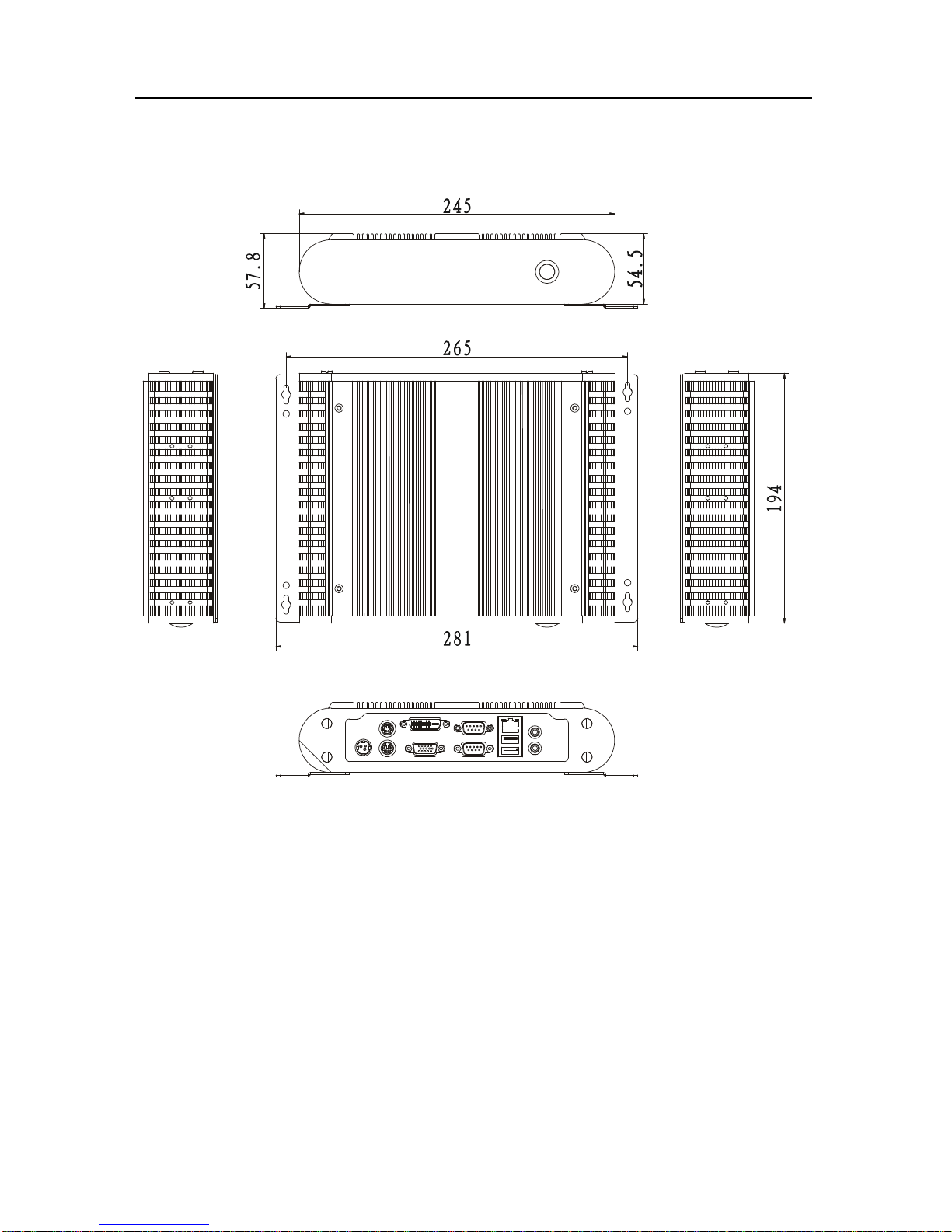
●Dimension:245mm(W)x194mm(H)x54.5mm(D)(9.65” x7.64” x 2.15”)
●Weight:3.5Kg±0.5Kg
Environment Specifications
●Operating Temperature: 0 ~60℃℃
●Operating Humidity:5%~90%,No Condensation
BIS-6540HD
Based on Intel Atom Processor Full HD Compact Signage Platform
4
1.4 Dimensions Diagram
Dimension:245mm(W)x194mm(H)x54.5mm(D)(9.65” x7.64” x 2.15”)

Chapter 2
Hardware Functionality
BIS-6540HD Based on Intel Atom Processor Full HD Compact Signage Platform
5
Chapter2 Hardware Functionality
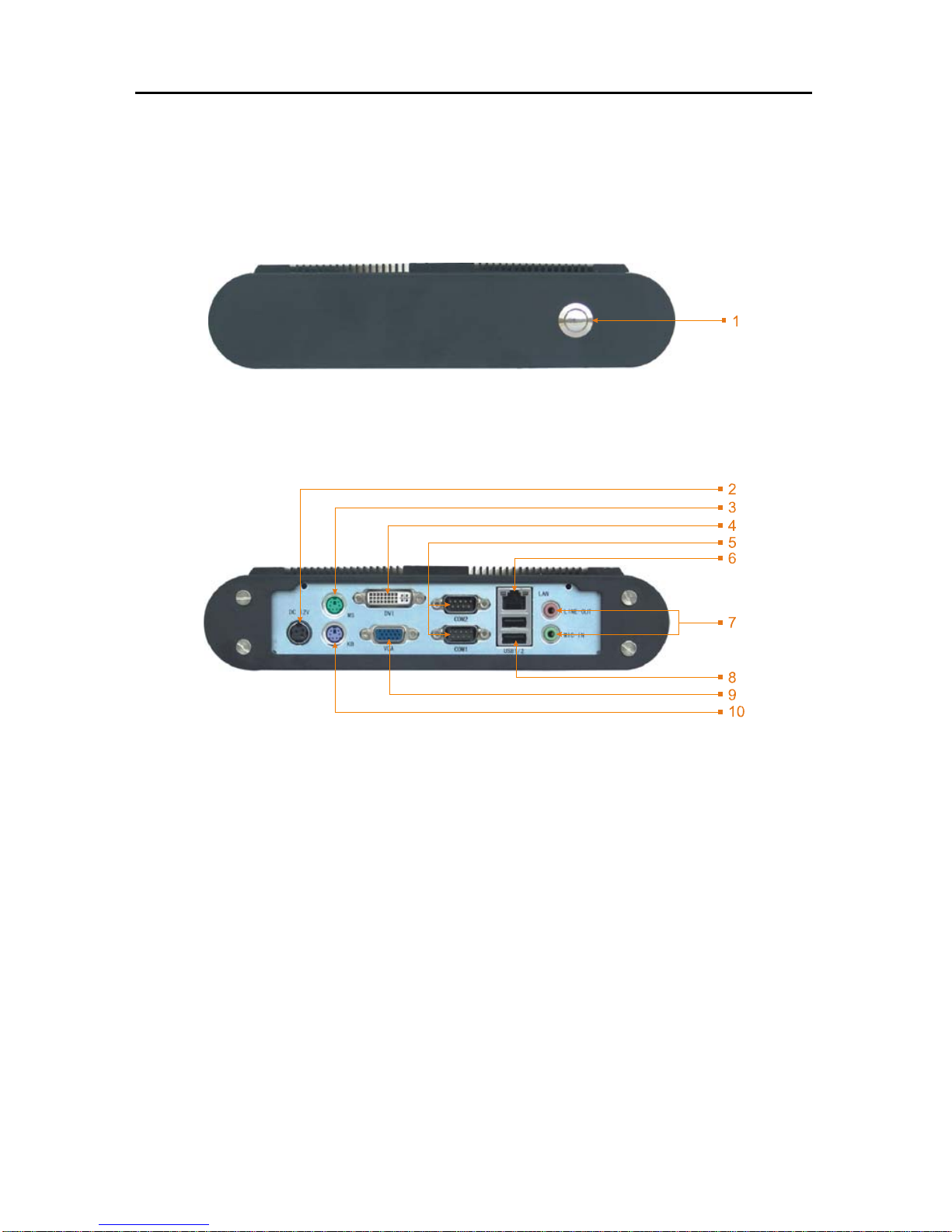
2.1 External I/O Connectors
1:BIS-6540HD Front Panel Diagram
1:Power Switch Button
2:BIS-6540HD Rear Diagram
2:Single Power Interface 3:PS/2 Mouse Connector
4:DVI Connector 5:Serial Ports
6:Ethernet Interface 7:Audio Ports(Pink for Line-out,Green for MIC-in)
8:USB Port 9:VGA Connector
10:PS/2 Keyboard Connector
BIS-6540HD Based on Intel Atom Processor Full HD Compact Signage Platform
6
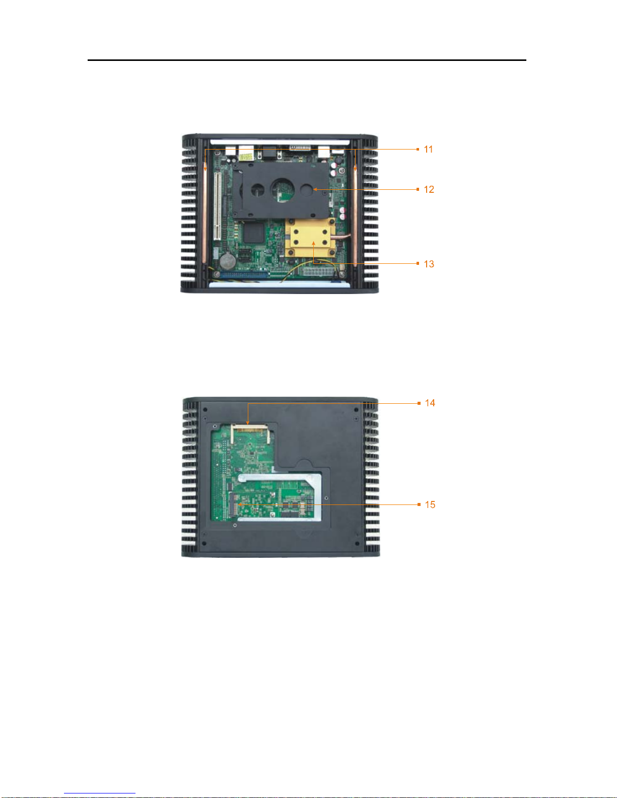
2.2 Internal Structure
Internal 1:
11:Heat Pipe 12:2.5”HDD Bay
13:Heatsink
Internal 2:
14:CF Socket 15:Mini PCI Socket
BIS-6540HD Based on Intel Atom Processor Full HD Compact Signage Platform
7
2.3 Back Panel I/O Connectors
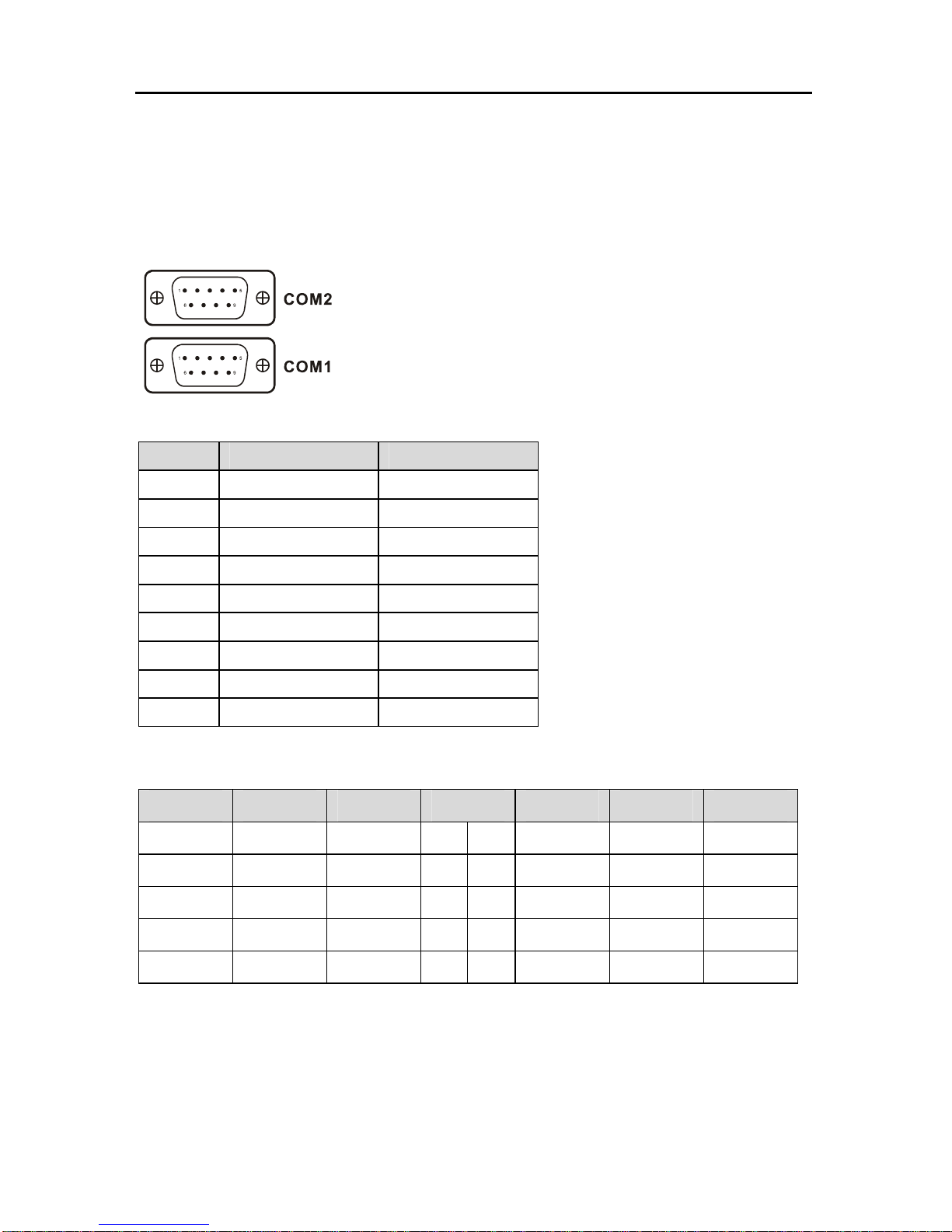
2.3.1 Serial Port(COM1,COM2)
The BIS-6540HD provides a D-sub 9-pin connector (COM1, COM2), COM1 Support
RS232 mode, COM2 support RS232/422/485 mode.
COM1:
Pin Definition Signel description
1 DCD Data Carrier Detect
2 RXD Receive Data
3 TXD Transmit Data
4 DTR Data Terminal Ready
5 GND Ground
6 DSR Data Set Send
7 RTS Request To Send
8 CTS Clear To Send
9 RI Ring Indicator
When COM2 is set as RS232/RS422/RS485, pins define as following:
RS485 RS422 RS232 Pin RS232 RS422 RS485
DATA- TX- DCD 1 2 RXD TX+ DATA+
NC RX+ TXD 3 4 DTR RX- NC
GND GND GND 5 6 DSR NC NC
NC NC RTS 7 8 CTS NC NC
NC NC RI 9
2.3.2 USB Port(USB)
The BIS-6540HD provides 2 connectors for USB interface, which gives complete Plug &
Play and hot swapping for up to 127 external devices. The USB interface complies with USB
UHCI, Rev. 2.0 compliant. The USB interface can be disabled in the system BIOS setup.The
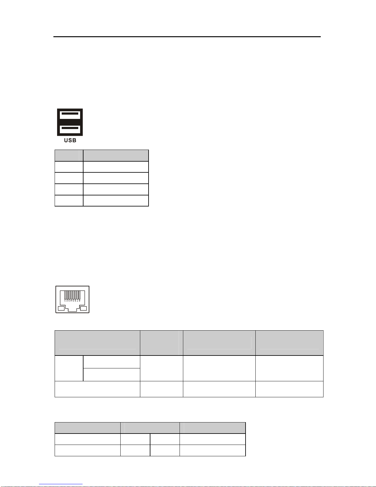
BIS-6540HD Based on Intel Atom Processor Full HD Compact Signage Platform
8
USB connector is used for connecting any device that conforms to the USB interface.Many
recent digital devices conform to this standard. The USB interface supports Plug and Play,
which enables you to connect or disconnect a device whenever you want, without turning off
the computer.
Pin Definition
1 VCC
2 USB_P+
3 USB_P-
4 GND
2.3.3 Ethernet connector(LAN)
The BIS-6540HD is equipped with an REALTEK 8111C (WOL supported) Fast Ethernet
controller that is fully compliant with IEEE 802.3u 10/100Base-T CSMA/CD standards .The
Ethernet port provides a standard RJ-45 jack connector with LED indicators on the front side to
show its Active/Link status (Green LED) and Speed status (Orange LED).
RJ45 PORT LED state description:
LILED state
Network link
status
ACTLED(Yellow) state Message transfer status
Green(100Mbps)
On
Orang(1000Mbps)
effective On transfering
Off noneffective Off No message transfering
LAN definition:
Signal Name Pin Signal Name
TX+ 1 2 TX-
RX+ 3 4 NC
BIS-6540HD Based on Intel Atom Processor Full HD Compact Signage Platform
9
NC 5 6 RX-
NC 7 8 NC
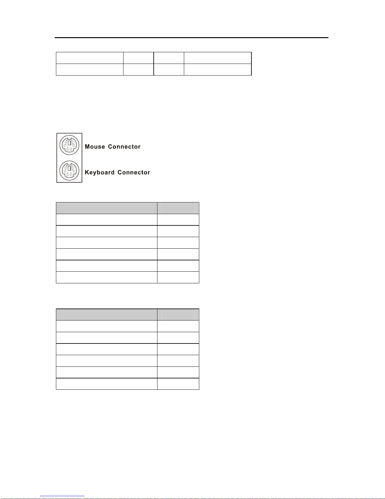
2.3.4 PS2 Keyboard/Mouse Connector(MS,KB)
The BIS-6540HD provides a PS/2 keyboard and PS/2 mouse connector. Green is the
mouse connector, purple is the keyboard connector.
MS:
Definition Pin
+5V 7
GND 8
NC 9
MS_DATA 10
MS_CLK 11
GND 12
KB:
Definition Pin
+5V 1
GND 2
NC 3
KB_DATA 4
KB_CLK 5
GND 6
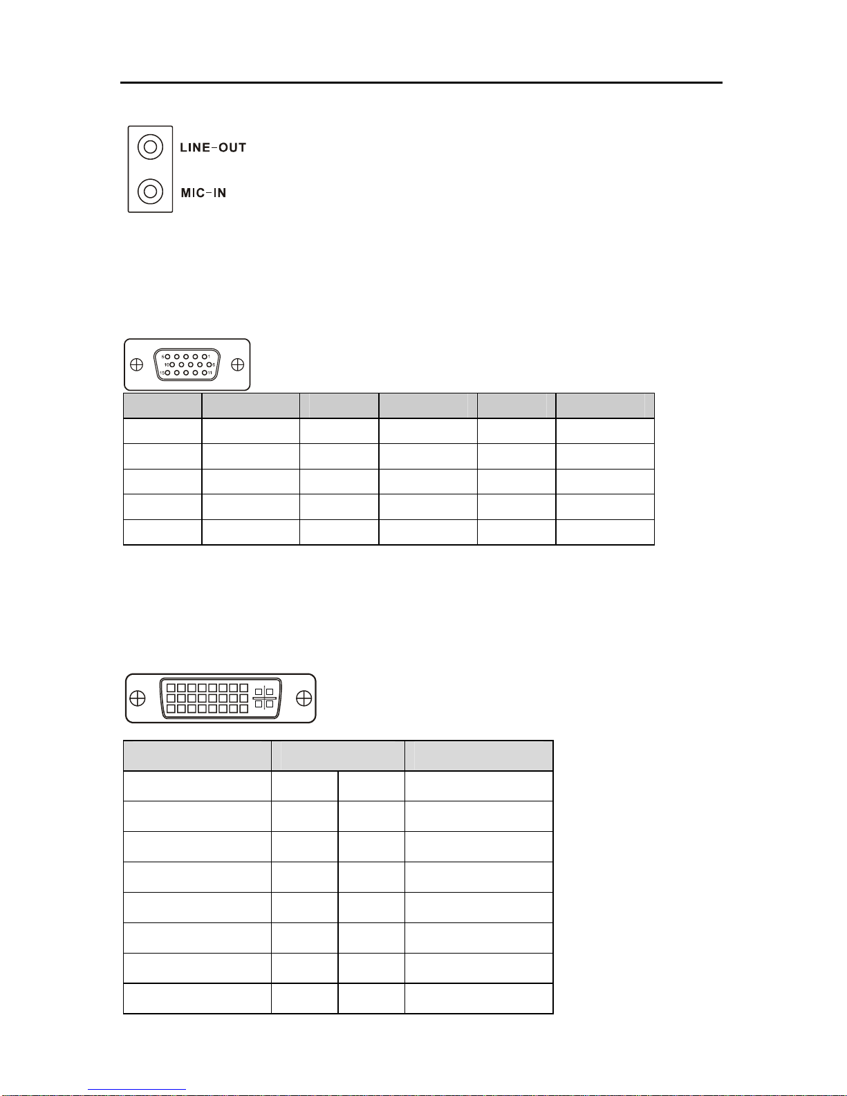
2.3.5 Audio Jack(LINE-OUT,MIC-IN)
BIS-6540HD using ALC888 audio decoder chip, support 7.1-channel, in the back panel
provides an audio output and MIC jack.
BIS-6540HD Based on Intel Atom Processor Full HD Compact Signage Platform
10
2.3.6 VGA Connector(VGA)
The BIS-6540HD provides a high resolution VGA interface by a D-sub 15-pin connector to
support a VGA CRT monitor.
Pin Signal Name Pin Signal Name Pin Signal Name
1 Red 6 GND 11 NC
2 Green 7 GND 12 SDA
3 Blue 8 GND 13 HSYNC
4 NC 9 +5V 14 VSYNC
5 GND 10 GND 15 SLC
2.3.7 DVI Connector(DVI)
The BIS-6540HD provides a high resolution DVI interface by a D-sub 28-pin connector to
support a DVI LCD monitor.
Signal Name Pin Signal Name
TDC2# 1 2 TDC2
GND 3 4 NC
NC 5 6 SC-DDC
SD-DDC 7 8 NC
TDC1# 9 10 TDC1
GND 11 12 NC
NC 13 14 VCC
GND 15 16 HP-DETECT
BIS-6540HD Based on Intel Atom Processor Full HD Compact Signage Platform
11
TDC0# 17 18 TDC0
GND 19 20 NC
NC 21 22 GND
TLC 23 24 TLC#
GND 25 26 GND
NC 27 28 NC
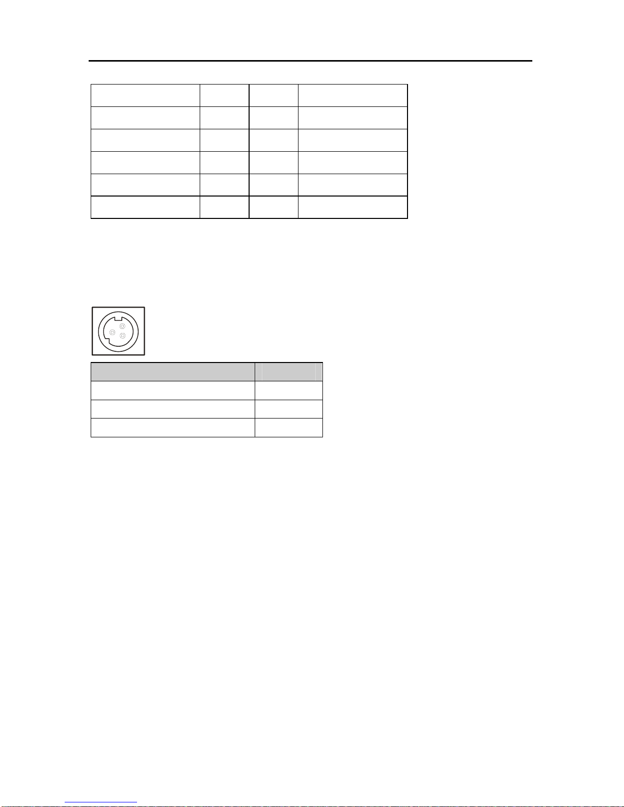
2.3.8 Power input connector(POWER)
The BIS-6540HD comes with a connector that carries +12 VDC external power input.
Signal Name Pin
+12V 1
GND 2
GND 3
BIS-6540HD Based on Intel Atom Processor Full HD Compact Signage Platform
12
2.4 Inside connectors
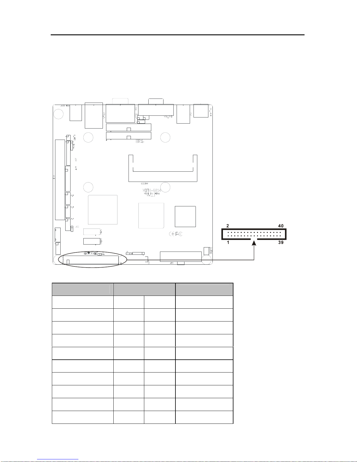
2.4.1 IDE Connector(IDE1)
This IDE connector is for 2 IDE devices. If you have two IDE hard disks in system, the
second disk must be set as slave disk by jumper setting.
IDE:
Pin Name Pin
Pin Name
IDERST# 1 2 GND
DDP 7 3 4 DDP 8
DDP 6 5 6 DDP 9
DDP 5 7 8 DDP 10
DDP 4 9 10 DDP 11
DDP 3 11 12 DDP 12
DDP 2 13 14 DDP 13
DDP 1 15 16 DDP 14
DDP 0 17 18 DDP 15
GND 19 20 VCC
BIS-6540HD Based on Intel Atom Processor Full HD Compact Signage Platform
13
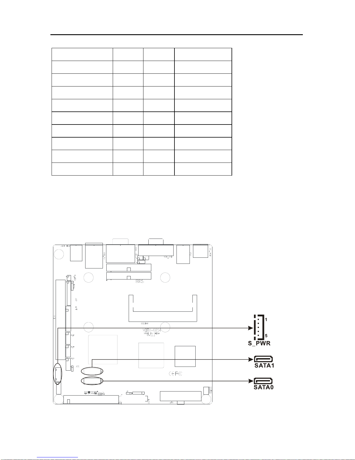
2.4.2 SATA Connector&SATA Power Connector(SATA0,SATA1,S_PWR)
BIS-6540HD supports Serial ATA via two connectors (SATA0, SATA1). Data transfer rates
up to 300 MB/s, enabling very fast data and file transfer, and independent DMA ope ration on
two ports.
SATA Port Pin define:
IDE_PDDREQ# 21 22 GND
IDE_PDIOW 23 24 GND
IDE_PDIOR 25 26 GND
IDE_PIORDY 27 28 ALE
IDE_PDDACK# 29 30 GND
INT_RQR14 31 32 NC
IDE_PDA1 33 34 P66DET#
IDE_PDA0 35 36 IDE_PDA2
IDE_PDCS1# 37 38 IDE_PDCS3
ACTP# 39 40 GND
BIS-6540HD Based on Intel Atom Processor Full HD Compact Signage Platform
14
Pin Pin Name
1 GND
2 SATA_TXP
3 SATA_TXN
4 GND
5 SATA_RXN
6 SATA_RXP
7 GND
S_PWR(SATA Power Connector):
Pin Pin Name
1 +12V
2 GND
3 VCC
4 GND
5 VCC3
 Loading...