

Norco BIS-6380F User Manual

BIS-6380F

SZ HQ: 0755-27331166
BIS-6380F
Beijing Office: 010-82671166
Shanghai Office: 021-61212081
Chengdu Office: 028-85259319
Shenyang Office: 024-23960846
Xi’an Office: 029-88338386
Nanjing Office: 025-58015489
Wuhan Office: 027-87858983
Tianjin Office: 022-23727100
Singapore: 65-68530809
For more information, please visit:www.norco.com.cn

Disclaimer
Except for the accessories attached to the product as specified herein,
what is contained in this user manual does not represent the commitments
of NORCO Company. NORCO Company reserves the right to revise this
User Manual, without prior notice, and will not be held liable for any direct,
indirect, intended or unintended losses and/or hidden dangers due to
installation or improper operation.
Before ordering products, please learn about the product performance
from the distributors to see if it is in line with your needs. NORCO is a
registered trademark of Shenzhen NORCO Intelligent Technology CO., LTD.
The ownership of other trademarks involved in this manual is owned by its
respective owners.

Safety Instructions
1. Please read the product manual carefully before using this product.
2.Put all the unused or uninstalled boards or electronic components in a static dissipative
surface or static shielding bag.
3.Always ground yourself to remove any static discharge before touching the board, to place
your hands on grounding metal object for a while or wear a anti-static wrist strap at all times.
4.When taking or fetching the boards or cards, please wear anti-static gloves and have the
habit of holding the boards by its edges.
5.Make sure that your power supply is set to the correct voltage in your area. Incorrect voltage
may cause personal injuries and damage the system.
6.To prevent electronic shock hazard or any damage to the product, please ensure that all
power cables for the devices are unplugged when adding or removing any devices or
reconfiguring the system.
7.To prevent electrical shock hazard, disconnect the power cable from the electrical outlet
before relocating the system.
8.When adding or removing devices to or from the system, ensure that all the power cables for
the devices are unplugged in advance.
9.To prevent any unnecessary damage to the products due to frequent power on/off, please
wait at least 30 seconds to restart the unit after the shutdown.
10.If system goes wrong during the operation, do not try to fix it by yourself. Contact a qualified
service technician or your retailer.
11.This product is classified as Class A product, which may cause radio interference in our
living environment. On this occasion, users need to take measures to handle the interference.

Content
Chapter One Product Introduction
1.1 Hardware Specificattion........................................................................................................... 1
Chapter Two Installation Specification
Safe Instructions
2.1 Front View Side Map of Mainframe........................................................................................6
2.2 Rear View Side Map of Mainframe.........................................................................................7
Chapter Three Hardware Function
3.1 External Interface Indicator Diagram......................................................................................3
3.1 Interface Location and Dimensional Drawing....................................................................... 6
3.2 Installation Steps....................................................................................................................... 7
3.3 Jumper Settings.........................................................................................................................8
3.3.1 COM1 Jumper(J1,J2)
3.3.2 COM2_3 Jumper(J3,J4)
3.3.3 System Programmer Jumper(JFP)
3.4 Interface Specification............................................................................................................10
3.4.1 Serial Port(COM1,COM2_COM3,COM4_COM7)
3.4.2 USB Port(USB2_12,USB3_12,USB3_34 ,OTG)
3.4.3 Ethernet Interface(LAN)
3.4.4 Headphone Jack(HEADPHCNE)
3.4.5 Power Amplifier Interface(SPEAKER)
3.4.6 Display Port(HDMI ,LVDS,JLVDS,J11,DP)
3.4.7 Programmable Input and Output Port(GPIO)
3.4.8 Port(SIM、TF)
3.4.9 Power Interface(PWR)
3.4.10 WIFI Port(ANT1)
3.4.11Front Panel Interface(JFP)
3.4.12 MINI PCIe Port...........................................................................................................20
3.4.13 PCIe Port.....................................................................................................................20
3.4.14 CIF_CAMERA and MIPI_CAMERA Port (CIF_CAMERA3,MIPI_CAMERA1-2)
..................................................................................................................................................21
Chapter Four Software Function
.............................................................................................
..................................................................
............................................................................................
....................................................................................................
............................................................................................
.......................................................................................
........................................................................
........................................................................................
.........................................................................
.................................................................
....................................................
.........................................................................................................
...........................................................................................
...................................................................................................
...................................................................................
.....................................................................................................
错误!未定义书签。
错误!未定义书签。
.......................................
.......................................
............................................
4
3
8
9
9
10
11
12
13
14
14
17
18
18
19
19
21

4.1 Android 7.1 System.................................................................................................................21
4.1.1 HDMI..............................................................................................................................21
4.1.2 DP...................................................................................................................................21
4.1.3 LCD................................................................................................................................21
4.1.4 USB................................................................................................................................21
4.1.5 COM...............................................................................................................................21
4.1.6 CAN................................................................................................................................21
4.1.7 TF Card......................................................................................................................... 22
4.1.8 WIFI................................................................................................................................22
4.1.9 BT...................................................................................................................................22
4.2.0 3/4G............................................................................................................................... 22
4.2.1 Ethernet.........................................................................................................................22
4.2.2 Sound Card...................................................................................................................22
4.2.3 DVP Camera.................................................................................................................22
4.2.4 PCIE Port...................................................................................................................... 23
Appendix
................................................................................................................................................
Appendix one: Glossary................................................................................................................26
26

Packing List
1pcs
1pcs
1pcs
1pcs
Thanks for purchasing NORCO products. Please check the
accessories as per the packing list when you open the package. If you find
any components/parts defected, damaged or lost, please contact your
vendor ASAP.
■BIS-6380F
■DC12V 5A Power Adapter
■Original Power Cord
■Drive CD

Chapter
One
Product
Introdu
ction

BIS-6380F User's Manual
Chapter One Product Introduction
1.1 Hardware Specification
Size
●Size:146mmX102mm
Processor
●CPU:RK3399 ,hexa-core (dual core A72 2GHz + quad core A53 1.5GHz)
System Memory
●On board memory:2G/4G DDR3
Display
●1xDP,supporting resolution: 4Kx2K@60Hz
●1xLVDS,supporting resolution: 1920 x1080@60Hz
●1xHDMI, supporting resolution: 4Kx2K @60Hz
●Supporting independent dual display;
Storage
●1xTF card slot,memory up to 64G
●On board 16G/32G/64G EMMC
AUDIO
●Adopt ES8316+NS4258T audio control chip
●One 2X4 connector,supporting dual channel amplifier output and 1x MIC audio input.
●On-board power amplifier chip , support 5W dual-channel power amplifier , provide an
on-board CTIA standard headphone jack.
LAN
●On board RJ45 network port ,support 100/1000M network
I/O
1

BIS-6380F User's Manual
●Serial port : Provides 6xserial port , in which COM1/3->RS232/RS485/TTL ;
COM4-7->RS232/TTL
●USB: 7xUSB port;in which 4xUSB3.0 and 2xUSB2.0,1xOTG port
●1xPWM
●1xI2C port
Expansion Port:
●1xMINI PCIe slot,support 3G/4G /wireless network card optional
●1xSIM card slot;support NANO SIM card
●1xPCIEX4 slot,support PCIE network card
●2xMIPI_CSI port,support MIPI CAMERA
●1xCIF CAMERA port;
●1x2.00mm 2x6PIN JFP front panel interface
●One 2x15PIN GPIO port,including 12bit GPIO(configurable SPI/I2S),1x MIPI_DSI
●1xon board WIFI module
Power Supply
●Single power supply + 12V,supports hardware and software switch for system auto boot upon
power on
Watchdog
●Supports hardware reset
Operating Environment
●Operating Temperature:0℃~60℃
●Operating Humidity:5%~95%,non condensing
2

Chapter
Two
Install
ation
Specifi
cation
BIS-6380F User's Manual
3

BIS-6380F User's Manual
Chapter Two
Installation Specification
Safety Instructions
Current can be used to achieve many useful functions, but it can also cause personal injury and
property loss due to improper use. In the design and manufacture of this product, "safety" is
considered as the first condition. However, electric shock and fire caused by improper use are
not excluded. Therefore, in order to ensure the safety of your personal and property and
prolong the service life of the product, please read in detail and follow the following product
safety instructions for installation and use.
Safety warning!
At any time, before operating the equipment, be sure to disconnect the power supply of the
chassis to prevent electric shock. Do not connect any original on CPU card or other card when
power is connected. Please disconnect the power supply before changing any configuration, so
as not to damage sensitive electronic components by instantaneous surge when connecting
jumpers or installing cards.
Attention!
• Before touching the CPU, be sure to place your hand on a grounded metal object for a while
to release static electricity from your body and hands. Modern electronic equipment is very
sensitive to static electricity. In order to be safe, anti-static bracelets must be worn at all times
when operating equipment. Place unused or uninstalled electronic components on the surface
of electrostatic dissipation objects or in antistatic protection bags.
• The data and pictures listed in this article are for illustration purposes only and are subject to
change without notice.
Safety instructions
4

BIS-6380F User's Manual
Electrical safety
·If the power supply is damaged, please do not repair it by yourself. You need to find a
professional to deal with it or contact your distributor.
·When you connect or unplug any device, make sure that the power cord of all devices is
unplugged beforehand before the signal cable is connected.
·To avoid the danger of electric shock, the AC power supply should be switched off or the AC
power line should be removed from the power socket every time the system is unplugged or
reconfigured.
· Before connecting and disconnecting the signal cables on the motherboard, make sure that
all the power cables of the equipment have been unplugged beforehand.
·Do not pull, bend or place heavy objects on the power line or cause any damage to the power
line, otherwise fire or electric shock may occur.
·Make sure to set the correct power supply voltage, otherwise it may cause personal injury or
system damage.
Note:
Current can be used to achieve many useful functions, but it can also cause personal injury and
property loss due to improper use. In the design and manufacture of this product, "safety" is
considered as the first condition. However, electric shock and fire caused by improper use are
not excluded. Therefore, in order to ensure the safety of your personal and property and
prolong the service life of the product, please read and follow the following products in detail.
Operational safety
·Before installing the motherboard or connecting equipment, please read the safety
instructions attached to the product packaging carefully.
·In order to avoid short circuit of the system, please keep the clip, screw, stapler and other
items away from connectors/interfaces, slots, sockets and circuits.
·Do not use equipment in damp and dusty environments or in environments where systems or
equipment are easily exposed to oil, steam, etc. Otherwise, fire accidents may occur.
·Make sure that the equipment is not exposed to water or other forms of liquid, and check
whether there are other objects left in the system, such as paper clips, pins, etc. Otherwise, it
may cause electric shock to the human body.
5
BIS-6380F User's Manual
Remove the four bolts on
the product and remove the
top cover.
·Avoid causing damage to the system or equipment. Do not place the equipment on unsafe
surfaces or let the equipment or system fall or overturn due to strong impact or shock.
·Do not use equipment or system near heat dissipation equipment or in high temperature
environment, which may cause system overheating and fire.
·Never expose the equipment to direct sunlight.
The data and pictures listed in this article are for illustration only. If there are any changes, no
further notice will be given.
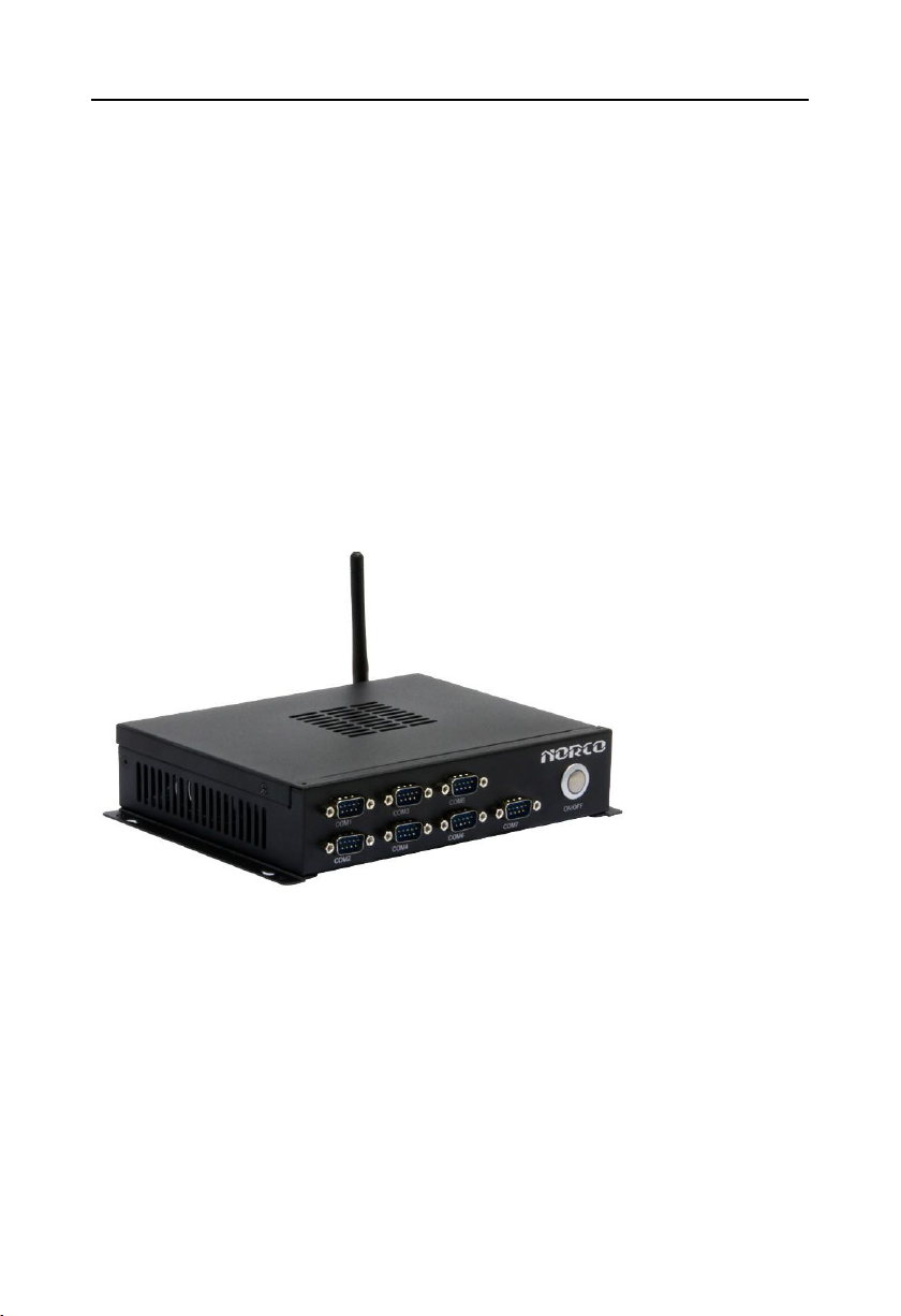
2.1 Front View Side Map of Host
6
 Loading...