

Norco BIS-6330A User Manual

BIS-6330A
Digital Signage Player
USER' Manual V1.0

Shenzhen HQ:0755-27331166
Beijing: 010-82671166
Shanghai: 021-61212081
Chengdu: 028-85259319
Shenyang: 024-23960846
Xi’an: 029-88338386
Nanjing: 025-58015489
Wuhan: 027-87858983
Tianjin: 022-23727100
Singapore: 65-68530809
For more product information, please visit www.norco.com.cn
BIS-6330A
Digital Signage Player
USER' Manual V1.0

Shenzhen NORCO Intelligent Technology Co.,Ltd.
Shenzhen NORCO Intelligent Technology Co.,Ltd.
BIS-6330A Network Digital Signage Platform
Place/Date: HONG KONG/2011
Trade Name:Shenzhen NORCO Intelligent Technology Co.,Ltd.
Model Name:BIS-6330A
Responsible Party:Shenzhen NORCO Intelligent Technology Co., Ltd.
Equipment Classification:FCC Class B Subassembly
Type of Product:BIS-6330A Network Digital Signage Platform
Manufacturer:
Shenzhen NORCO Intelligent Technology Co.,Ltd.
Date: 2011

Disclaimer
Except for the accessories attached to the product as specified herein, what
is contained in this user manual does not represent the commitments of
NORCO Company. NORCO Company reserves the right to revise this User
Manual, without prior notice, and will not be held liable for any direct, indirect,
intended or unintended losses and/or hidden dangers due to installation or
improper operation.
Before ordering products, please learn about the product performance from
the distributors to see if it is in line with your needs. NORCO is a registered
trademark of Shenzhen NORCO Intelligent Technology CO.,LTD. The
ownership of other trademarks involved in this manual is owned by its
respective owners.
The contents of this manual are protected by copyright law. All rights are
strictly reserved. Any form of unauthorized reproduction including but not
limited to carbon copy, facsimile transmission and electronic copy or email is
prohibited.

Safety Instructions
1. Please read this manual carefully before using the product.
2.To prevent electronic shock hazard or any damage to the product, please
ensure that all power cables for the devices are unplugged when adding or
removing devices or reconfiguring the system.
To prevent electrical shock hazard, disconnect the power cable from the
3.
electrical outlet before relocating the system.
When adding or removing devices to or from the system, ensure that all
4.
the power cables for the devices are unplugged in advance.
5. To prevent any unnecessary damage to the products due to frequent
power on/off, please wait at least 30 seconds to restart the unit after the
shutdown.
6. Use cross screwdriver to operate the device. Magnetic screwdriver would
be better to avoid leaving any screws inside the case. Do not leave any
tools or screws inside the case.
7. Keep the system good cooling or ventilation.
8. If system goes wrong during the operation, do not try to fix it by yourself.
Contact a qualified service technician or your retailer.

Table of Contents
Chapter 1 Product Introduction .................................................................................................. 1
1.1 Overview ....................................................................................................................... 1
1.2 Specifications ................................................................................................................ 1
Chapter 2 Product Features ....................................................................................................... 4
2.1 External Interfaces Location ......................................................................................... 4
2.2 Front Panel I/O .............................................................................................................. 4
2.2.1 Audio(Speak-out, Mic-in) ................................................................................ 4
2.2.2 LED ..................................................................................................................... 4
2.2.3 USB3.0(USB1/2) ........................................................................................... 5
2.2.4 Ethernet(LAN) ................................................................................................ 5
2.2.5 HDMI ................................................................................................................... 5
2.3 Inner Interfaces ............................................................................................................. 6
2.3.1 SATA Port(SATA1) .......................................................................................... 6
2.3.2 Display Interfaces(HDMI1,Display Port) ........................................................ 8
2.3.3 JBAT ................................................................................................................... 9
2.3.4 FAN Interface(CPUFAN) .............................................................................. 10
2.5.5 MINI PCIe(MINI PCIe) ................................................................................. 10
2.3.6 Serial Port(COM1) ........................................................................................ 11
Chapter 3 Installation Instructions ............................................................................................ 12
3.1 Jumper Setting ............................................................................................................ 12
3.1.1 CMOS Clear/Hold Jumper Setting(JCC) ..................................................... 12
3.1.2 Pins for System Auto Boot upon Restore AC Power(JAT) ........................... 14
3.2 Install Memory ............................................................................................................. 14
3.3 Install HDD ................................................................................................................. 15
3.4 Product Dimension Diagram ....................................................................................... 15
Chapter 4 BIOS SETUP ........................................................................................................... 16
AMI BIOS Flash ......................................................................................................... 16
AMI BIOS Description ................................................................................................ 16
BIOS Settings ............................................................................................................ 16
3.1 Main Menu .................................................................................................................. 17
3.2 Advanced .................................................................................................................... 18

3.2.1 ACPI Configuration ........................................................................................... 20
3.2.2 APM Configuration ............................................................................................ 21
3.2.3 CPU Configuration ............................................................................................ 22
3.2.4 SATA Configuration ........................................................................................... 25
3.2.5 Intel(R) Rapid Start Technology ........................................................................ 26
3.2.6 USB Configuration ............................................................................................ 27
3.2.7 Supper IO Configuration ................................................................................... 29
3.2.8 H/W Monitor ...................................................................................................... 32
3.2.9 CPU PPM Configuration ................................................................................... 36
3.3 Chipset Menu .............................................................................................................. 38
3.3.1 North Bridge ...................................................................................................... 39
3.3.2 South Bridge ..................................................................................................... 40
3.4 Boot Menu ................................................................................................................... 41
3.5 Security Menu ............................................................................................................. 43
3.6 Save&Exit Menu ......................................................................................................... 44
Appendix .................................................................................................................................. 45
Appendix 1: Watchdog Programming Guide ..................................................................... 45
Appendix 2: Glossary ........................................................................................................ 46
Appendix 3: Install Driver .................................................................................................. 49

Packing List
Thanks for purchasing NORCO products. Please check the accessories as
per the packing list when you open its package. If you find any defect
components or anything damaged or lost, please contact your vendor ASAP.
■BIS-6330A
■Drivers and Utilities
■Screws
1 Unit
1 pcs
4pcs

Chapter 1. Product
Introduction

BIS-6330A Digital Signage Player
Chapter 1 Product Introduction
1.1 Overview
Taking advantage of Intel’s new OPS standard, the BIS-6330A combines compact size and
cutting-edge Technology to provide for greater scalability for digital signage applications.
The BIS-6330A Intel 2nd/3rd Generation Core i3/i5 capable OPS module is built to last under
dusty extreme temperature environments with a rugged fully-enclosed solid state design. In
addition, the system pushes for eco-friendliness with low power consumption. The draw-out
type module design enables easy data upgrading. This embedded OPS module is rich with
I/O’s including two USB 2.0, one Gigabit Ethernet, Two HDMI video with up to 1920x1200
resolution, expandability of 1x SATA I/II/III drives and one Mini PCIe / one PCIe for antennas for
wireless communication. The BIS-6330A hopes to bring functional as well as environmentally
conscious solutions to the embedded market.
This eco-friendly and cost effective digital signage solution can be deployed in most venues
such as restaurants, hotels, vehicles, flights, hospital, shopping mall, cinema, museum, etc.
1.2 Specifications
Processor
●CPU: Ivy Bridge Gen3 /Sandy Bridge Gen2 i3/i5
Chipset
●Chipset: HM76 Mobile
System Memory
●System Memory: 1x single channel SO-DIMM slot supports DDRIII 1066/1333/1600MHZ, up
to 4GB. Non-ECC.
1

BIS-6330A Digital Signage Player
Display
●Display Interface: 2x HDMI, 1x Display Port
●HDMI: Maximum resolution:1920x1200@60Hz, one is extended via OPS and one on the rear
panel.
●Display Port: Maximum resolution: 2560x1600@60HZ
Ethernet
●LAN Controller: PCIe LAN chip: RTL8111E
●Rate: 10/100/1000MBps
●Support Wake-on-LAN(WOL)
Storage
●Provide one 7+15 Pin SATA port
●Support SATAI/SATAII/SATAIII
AUDIO
● Adopt ALC887 audio controller chip; OPS connector supports Side Surround output. Rear
panel supports dual channel stereo output.
●Interface: Provide two single-jack sockets: MIC-in (pink); Speak-out(green)
I/O
●I/O Chip: W82627DHG
●Serial Port: OPS connector provides COM1 supporting RS232 mode.
USB
●Rear panel provides one double-layer USB3.0 socket. OPS connector provides 2x USB2.0,1x
USB3.0
Expansion Interface
●1x standard mini PCIe supports WiFi module
OPS Connector
2

BIS-6330A Digital Signage Player
●Standard OPS connector: including 1x HDMI, 1x Display Port, 1x COM, 2x USB2.0, 1x
USB3.0.
Power Supply
● Power supplied via OPS Interface
●Support 12V~19V power input
Watchdog
●Trigger system reset when the timer overflows
BIOS
●BIOS: 8MB SPI FLASH,AMI EFI BIOS
OS
●Support WIN XP, WIN7, WIN8
●Support WIN XPE, WIN7E
●Support LINUX
Operating Environment
●Operating Temperature: 0℃~40℃
●Storage Temperature: -20~80℃
●Operating Humidity: 5%~95%, non-condensing
3

Chapter 2. Product
Features
BIS-6330A Digital Signage Player
Chapter 2 Product Features
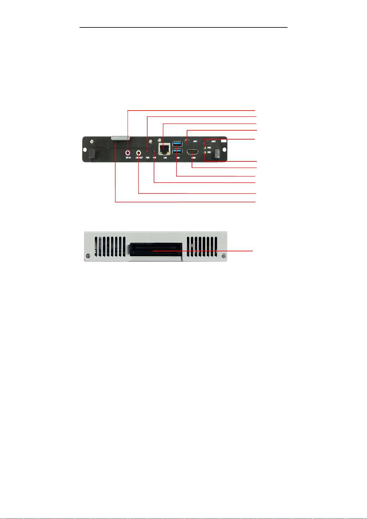
2.1 External Interfaces Location
1:BIS-6330A Front View
Mic-in
PWR
LAN
Antenna
PWR_LED
2:BIS-6330A Rear View
HDD_LED
HDMI
USB
Reset
Speak-out
SATA HDD
OPS Slot
2.2 Front Panel I/O
2.2.1 Audio(Speak-out, Mic-in)
BIS-6330A adopts ALC887 audio controller chip. The green one is Speak-out; the pink one is
the Mic-in.
2.2.2 LED
PWR_LED is on the upper layer. The LED beneath is the HDD_LED.
4
5 USB3
BIS-6330A Digital Signage Player
2.2.3 USB3.0(USB1/2)
BIS-6330A provides 2x USB3.0, compatible with USB2.0, PnP support.
Pin Signal Name
1 VCC_USB1
2 USBD_N0
3 USBD_P0
4 GND
RX1 R DN
6 USB3_RX1_R_DP
7 GND
8 USB3_TX1_R_DN
9 USB3_TX1_R_DP
10 VCC_USB1
11 USBD_N1
12 USBD_P1
13 GND
14 USB3_RX2_R_DN
15 USB3_RX2_R_DP
16 GND
17 USB3_TX2_R_DN
18 USB3_TX2_R_DP
2.2.4 Ethernet(LAN)
BIS-6330A provides 1x RJ-45 Gigabit Ethernet LAN Port with its pins defined as below. LILED
& ACTLED are the green LED and Yellow LED on both sides of the port, indicating the status of
the LAN port.
RJ45 LAN LED Status:
LILED(GREEN)
Flash Effective link On Data transfer
Function
ACTLED
(YELLOW)
Function
Off Non-effective link/Close Off No data
2.2.5 HDMI
BIS-6330A provides 1x HDMI port to transfer uncompressed audio signal and HD video signal
5

BIS-6330A Digital Signage Player
and no analog to digital / digital to analog conversion before transferring signal, securing high
quality signal transfer. HDMI supports 1x 1080P video signal and 1x 8CH audio signal.
Signal Name Pin Signal Name
D2+ 1 2 D2 Shield
D2- 3 4 D1+
D1 Shield
CK Shield
CE Remote 13 14 NC
DDC CLK
HP DET 19 20 SHELL0
SHELL1
SHELL3 23 24 SHELL4
SHELL5 25 26 SHELL6
SHELL7 27 28 SHELL8
SHELL9 29 30 SHELL10
SHELL11 31
D0+ 7 8 D0 Shield
D0- 9 10 CK+
GND
5 6 D1-
11 12 CK-
15 16 DDC DATA
17 18 +5V
21 22 SHELL2
2.3 Inner Interfaces
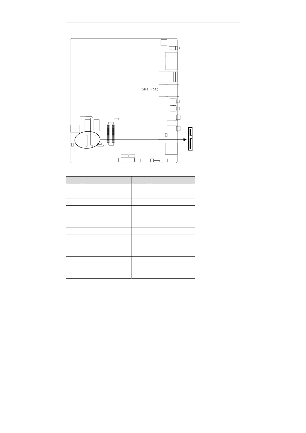
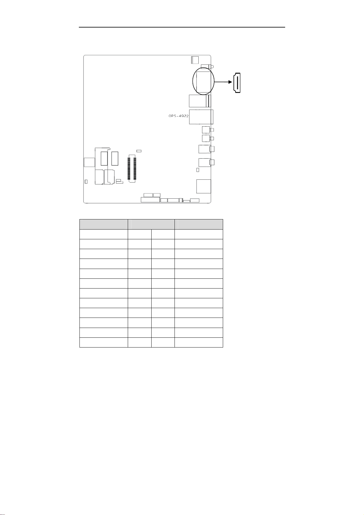
2.3.1 SATA Port(SATA1)
System provides one standard 7+15Pin SATA Port.
6
BIS-6330A Digital Signage Player
SATA1:
Pin Signal Name Pin Signal Name
1 GND P4 GND
2 TX+ P5 GND
3 TX- P6 GND
4 GND P7 VCC
5 RX- P8 VCC
6 RX+ P9 VCC
7 GND P10 GND
8 NC P11 GND
9 GND P12 GND
10 NC P13 +12V
P1 VCC3 P14 +12V
P2 VCC3 P15 +12V
P3 VCC3
7
BIS-6330A Digital Signage Player
2.3.2 Display Interface(HDMI1, Display Port)
HDMI1
HDMI1:
Signal Name Pin Signal Name
D2+ 1 2 D2 Shield
D2- 3 4 D1+
D1 Shield
CK Shield
CE Remote 13 14 NC
DDC CLK
HP DET 19 20 SHELL0
SHELL1
SHELL3 23 24 SHELL4
D0+ 7 8 D0 Shield
D0- 9 10 CK+
GND
5 6 D1-
11 12 CK-
15 16 DDC DATA
17 18 +5V
21 22 SHELL2
8
BIS-6330A Digital Signage Player
SHELL5 25 26 SHELL6
SHELL7 27 28 SHELL8
SHELL9 29 30 SHELL10
SHELL11 31
HDMI2, Display Port is provided via OPS connector
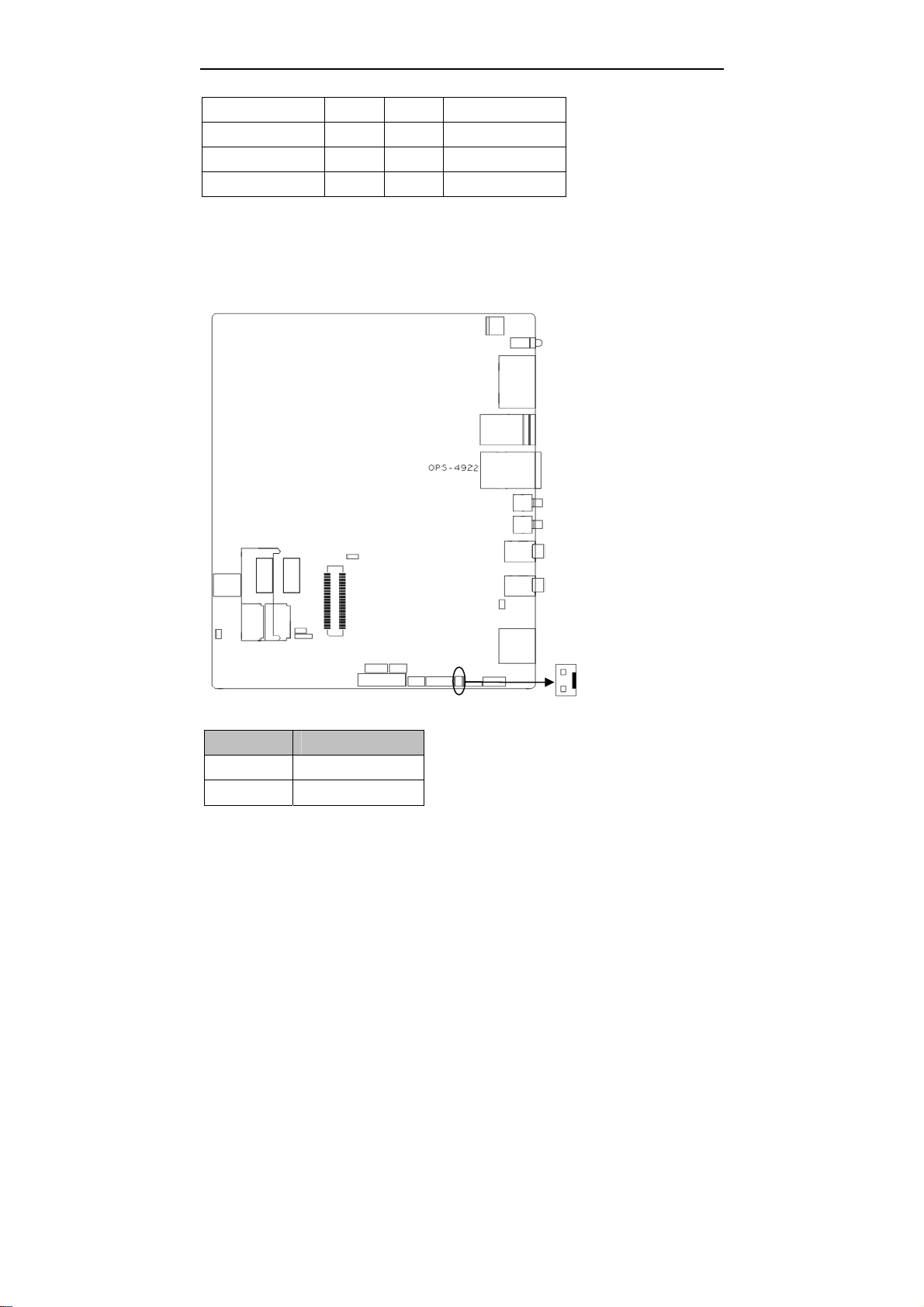
2.3.3 JBAT
JBAT:
Pin Signal Name
1 BAT+
2 GND
9
 Loading...