

Norco ATX-6991 User Manual

ATX-6991
Ver: V1.1

SZ HQ: 0755-27331166
ATX-6991
Ver: V1.1
Beijing Office: 010-82671166
Shanghai Office: 021-61212081
Chengdu Office: 028-85259319
Shenyang Office: 024-23960846
Xi’an Office: 029-88338386
Nanjing Office: 025-58015489
Wuhan Office: 027-87858983
Tianjin Office: 022-23727100
Singapore: 65-68530809
For more information, please visit www.norco-group.com

Disclaimer
Except for the accessories attached to the product as specified herein,
what is contained in this user manual does not represent the commitments
of NORCO Company. NORCO Company reserves the right to revise this
User Manual, without prior notice, and will not be held liable for any direct,
indirect, intended or unintended losses and/or hidden dangers due to
installation or improper operation.
Before ordering products, please learn about the product performance
from the distributors to see if it is in line with your needs. NORCO is a
registered trademark of Shenzhen NORCO Intelligent Technology CO., LTD.
The ownership of other trademarks involved in this manual is owned by its
respective owners.
The contents of this manual are protected by copyright law. All rights
are strictly reserved. Any form of unauthorized reproduction including but
not limited to carbon copy, facsimile transmission and electronic copy or
email is prohibited.

Safety Instructions
1. Please read the product manual carefully before using this product.
2 . Put all the unused or uninstalled boards or electronic components in a static dissipative
surface or static shielding bag.
3.Always ground yourself to remove any static discharge before touching the board, to place
your hands on grounding metal object for a while or wear a anti-static wrist strap at all times.
4. When taking or fetching the boards or cards, please wear antistatic gloves and have the
habit of holding the boards by its edges.
5.Make sure that your power supply is set to the correct voltage in your area. Incorrect voltage
may cause personal injuries and damage the system.
6.To prevent electronic shock hazard or any damage to the product, please ensure that all
power cables for the devices are unplugged when adding or removing any devices or
reconfiguring the system.
7. To prevent electrical shock hazard, disconnect the power cable from the electrical outlet
before relocating the system.
8.When adding or removing devices to or from the system, ensure that all the power cables for
the devices are unplugged in advance.
9. To prevent any unnecessary damage to the products due to frequent power on/off, please
wait at least 30 seconds to restart the unit after the shutdown.
10.If system goes wrong during the operation, do not try to fix it by yourself. Contact a qualified
service technician or your retailer.
11.This product is classified as Class A product, which may cause radio interference in our
living environment. On this occasion, users need to take measures to handle the interference.

Content
Chapter 1 Product Introduction
1.1 Product Introduction..................................................................................................................1
1.2 Hardware Specification............................................................................................................ 1
Chapter 2 Hardware Function
2.1 Interfaces Location & Dimension............................................................................................4
2.2 Installation Steps....................................................................................................................... 5
2.3 Memory Installation...................................................................................................................5
2.4 Jumpers Setting.........................................................................................................................6
2.4.1 CMOS Clear/Hold Jumper Setting(JCC)
2.4.2 Auto Boot upon Restore AC Power(JAT)
2.4.3 ME Function Setting(JME)
2.4.4 COM2 Jumpers Setting(J1,J2,J3)
2.5 Interface Specification............................................................................................................ 10
2.5.1 Serial Port(COM1,COM2,COM3-COM6,J9)
2.5.2 SATAPort(SATA1-SATA6)
2.5.3 USB and LAN Port(HDMI_USB12,USB34_LAN1,USB56_LAN2,USB56,
USB78,USB1112,USB1314,)
2.5.4 Keyboard and Mouse Interface(KM)
2.5.5 Audio Port(AUDIO,FP_AUDIO,J_SPDIFO,CD_IN)
2.5.6 Disdplay Port(VGA_DVI,HDMI_USB12,JDP)
2.5.7 Programmable Input and Output Port(JGP)
2.5.8 Power Interface(PWR,J12V)
2.5.9 Fan Interface(CPU_ FAN,SYS_ FAN)
2.5.10 Parallel Interface (LPT).............................................................................................23
2.5.11 LPC Bus Interface(JLPC)
2.5.12 Front Panel Interface(JFP)
2.5.13 Memory Slot............................................................................................................... 26
2.5.14 Expansion Port...........................................................................................................26
Chapter 3 BIOS Setup
AMI BIOS Refresh................................................................................................................. 24
AMI BIOS Description...........................................................................................................24
.........................................................................................................................
.........................................................................................................
............................................................................................................
..............................................................
..............................................................
......................................................................................
....................................................................
..............................................
....................................................................................
......................................................................................
...................................................................
..................................
..............................................
.......................................................
..............................................................................
..............................................................
....................................................................................
.................................................................................
1
4
6
8
9
9
10
12
13
15
15
17
19
20
21
24
25
24

BIOS Setup.............................................................................................................................24
3.1 Main Menu...............................................................................................................................25
3.2 Advanced Menu......................................................................................................................27
3.2.1 CPU Configuration......................................................................................................28
3.2.2 Power & Performance.................................................................................................31
3.2.3 ACPI Settings............................................................................................................... 36
3.2.4 F81866 Supper IO Configuration.............................................................................. 37
3.2.5 Hardware Monitor........................................................................................................ 42
3.2.6 Serial Port Console Redirection................................................................................ 43
3.2.7 USB Configuration.......................................................................................................45
3.2.8 CSM Configuration...................................................................................................... 46
3.3 Chipset Menu..........................................................................................................................48
3.3.1 System Agent(SA)Configuration
..........................................................................
3.3.2 PCH-IO Configuration................................................................................................. 52
3.3.3 SATAAnd RST Configuration.................................................................................... 54
3.4 Security Menu.........................................................................................................................55
3.5 Boot Menu................................................................................................................................57
3.6 Save & Exit Menu...................................................................................................................58
Appendix
................................................................................................................................................
Appendix 1:Watchdog Programming Guide
Appendix 2:Glossary
Appendix 3:Driver Installation
..................................................................................................................
...................................................................................................
...........................................................................
49
47
47
48
51

Packing List
1pcs
1pcs
1pack
Several
Thanks for purchasing NORCO products. Please check the
accessories as per the packing list when you open its package. If you find
any components/parts defected, damaged or lost, please contact your
vendor ASAP.
■ ATX-6991
■Drive CD
■Jumper cap
■Wires

Chapter
One
Product
Introdu
ction

ATX-6991 User's Manual
Chapter One Product Introduction
1.1 Product Introduction
ATX-6991 ATX motherboard is based on Intel 8thgeneration Coffee lake-S desktop
platform; Adopt Intel® 300 Series chipset ; Support 8th Gen Intel® Core i7/i5/i3 CPU, etc.
Provide 6xserial ports,14xUSB (4x USB3.0、10x USB2.0),6xSATA,1xLPT,1xKM ,Line out
+ MIC in+ Line in+ S/PDIF,8BitsGPIO,VGA+DVI+HDMI+DP,2xRJ45 network interface,
support Wake On LAN(WOL),2xPCI,2x PCIe 16X Slots,3xPCIe 1X Slots. It can meet the
needs of most professional customers in the current market. Mainly used in the field of multi
serial port, industrial automation, POS terminal, multi display and other industries.
1.2 Hardware Specification
Size
●Size: 305mmx 244mm
Processor
●CPU:Intel® Core™i7/i5/i3 CPU, etc.
Chipset
●Chipset:300 Series
System Memory
●System memory:4xdual channel DIMM memory slot,support DDRIV 2666/2400MHz,whole
board up to 64GB.
Display
●Display port:VGA、DVI、HDMI、JDP
●VGA:1x standard DB15 VGA port,support resolution up to: 1920X1200@60Hz
●DVI:1x DVI-D port,support resolution up to: 1920x1200 @60Hz
●HDMI:1xHDMI port,support resolution up to: 2560X1600@60Hz
●DP:1xDP port,support resolution up to: 4096X2304@60Hz
1

ATX-6991 User's Manual
Ethernet
●Network controller:Using PCIe interface chip,model:I211/I210(Can be selected according
to needs)
●Rate:10/100/1000Mbps self-adaption
●2xRJ45 network interface
●Support Wake On LAN(WOL)
Storage
●Provide 6xstandard 7Pin SATA3.0 port
Audio
●Adopt ALC662 audio control chip,support dual channel,stereo
●Port: 2x tip jacks( Green for Line-out,Pink for MIC-in),support Line out + MIC in+ Line
in+S/PDIF
I/O
●I/O chip:NCT6106D
●Serial port:Provide 6x serial ports,2xDB9 port,4x2*5P black 2.54mm spacing Box header
connector port(in which COM1-COM6 support RS232,COM2 also support RS422/485)
●USB:Provide 14xUSB ports,4x USB3.0、10x USB2.0 ports
●KBMS:Provide 1xKM pin
●LPT:Provide 1xLPT pin
Expansion port
●JFP:Provide one 2x5PIN 2.54mm dual pin header JFP
●LPC:Provide one 2X12PIN 2.0mm spacing dual female header LPC expansion port
●PCIe:Provide 7xPCIe slot,2xPCI,2xPCIe 16X Slots,3xPCIe 1XSlots
Power supply
●Standard ATX 24Pin + 4Pin power supply
Watchdog
●Supports hardware switch for system auto boot upon power on
2

ATX-6991 User's Manual
BIOS
●BIOS:AMI EFI
Operating Environment
●Operating Temperature:0℃~60℃
●Storage Temperature:-40~85℃
●Operating Humidity:5%~95%,non-condensing
●Storage Humidity:5%~95%,non-condensing
3

Chapter
Two
Hardware
Function
ATX-6991 User's Manual
4
Chapter Two Hardware Function
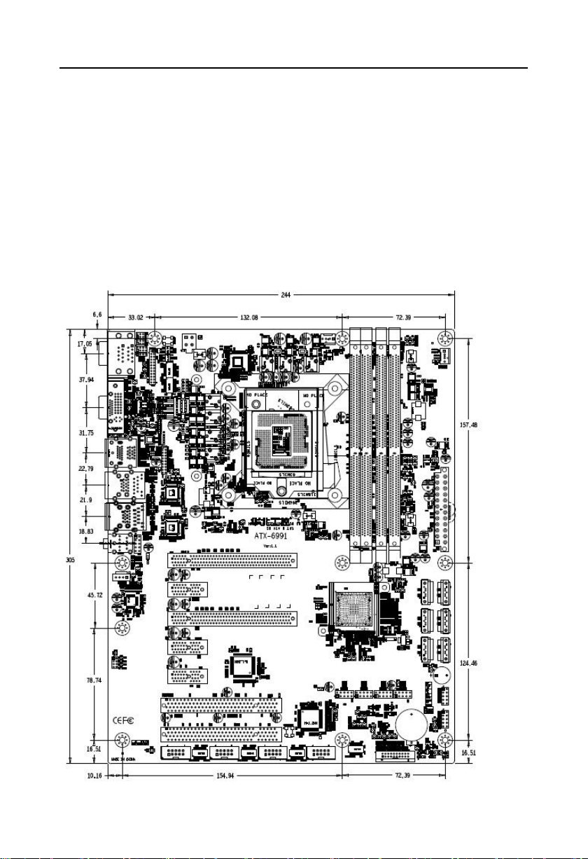
2.1 Interfaces Location & Dimension
Following picture illustrates the interfaces location and dimension of ATX-6991. Please
take care of some components during the installation. Improper installation may lead to
system failure.
Note: In case of any electrostatic damage caused to some components, please wear
anti-static gloves to install the motherboard.

ATX-6991 User's Manual
5
2.2 Installation Steps
Please refer to following steps to assemble your computer:
1.Adjust all jumpers on board ATX-6991 according to the user manual.
2.Install CPU and CPU fan
3.Install memory
4.Install other expansion cards
5.Connect all signal lines, cables, control panel circuit and power supply unit.
6.Start the computer and complete BIOS settings.
Key components of this motherboard are Integrated circuit and these components
could be easily damaged by electrostatic influence. So, before installing this unit, please
always keep the following precautions in mind:
1.Hold the board by edges and don’t touch any components, plugs or socket pins.
2.Wear anti-static gloves/wrist strap while touching the integrated circuit components, such as
CPU, RAM, etc.
3.Put those unused or uninstalled components in static shielding bags or trays.
4.Please first check the power switch is off before connecting the power plug.
2.3 Install Memory
ATX-6991 provides 4x dual channel DIMM memory slot,support DDRIV 2666/2400Mhz,
single slot up to 16G,whole board memory up to 64GB,please follow the steps below for
detailed installation:
1.During installation, align the notch of the memory module with the notch of the socket, and
then firmly insert it.
2. When selecting a memory module, you must select a memory module that supports this
motherboard specification.
Before installing the computer accessories
Following the instructions below will help to prevent your computer from being damaged,
and also ensuring your personal safety.
1.Please make sure your computer is disconnected from the power supply.
2.Please always wear anti-static strap or gloves to operate the board in case that you may
touch the integrated circuit components, such as RAM.

ATX-6991 User's Manual
6
2.4 Jumper Settings
Please refer to following instructions to do jumper settings before installing your hardware
devices.
Remark: How to identify the PIN1 of all jumpers and interfaces: Please observe the word
mark on the side of the plug socket, which will be a “1” or bold line or triangular symbol; And
please look at the back of PCB, each with a square shape will be the PIN 1; and all the jumpers’
PIN1 have a white arrow on the side.
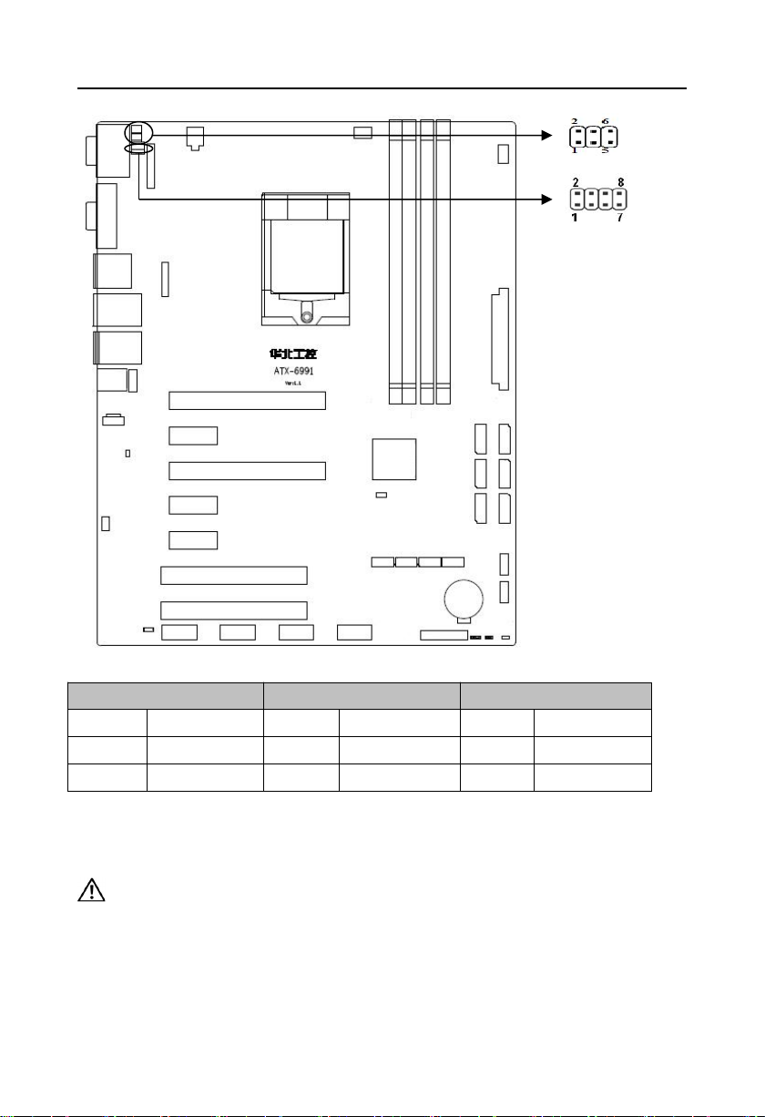
2.4.1 CMOS Clear/Hold Jumper Setting(JCC)
CMOS is powered by the onboard button cell. Clear CMOS will lead to permanent
elimination of previous system settings(factory default).
Steps:(1)Turn off the computer, disconnect power supply;
( 2 )Use jumper Cap JCC Pin1-3 short for 5~10 seconds, then restore the default
setting with Pin3-5 connected;
(3)Start the computer, then press “Del” to enter BIOS setting and reload optimal
defaults;
(4)Save and Exit.
ATX-6991 User's Manual
7
Setting
JCC
1-2
CLEAR
2-3
NORMAL
JCC
JCC:
Do not clear CMOS when the computer is power on, otherwise, it will cause damage to
the motherboard!
ATX-6991 User's Manual
8
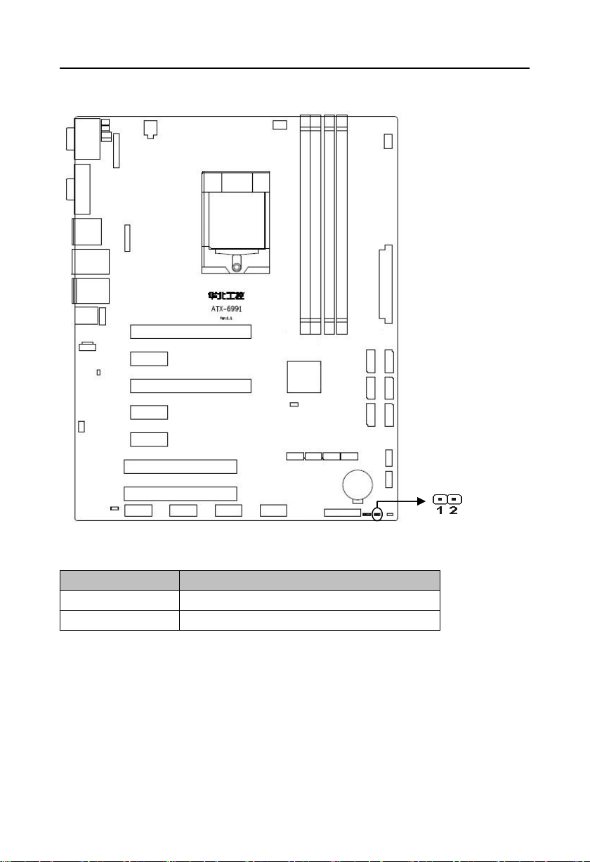
Setting
JAT
Open
Disable Auto Boot
Close
Enable Auto Boot
JAT
2.4.2 Hardware Switch for System Auto Boot upon Power On(JAT)
JAT:
ATX-6991 User's Manual
9
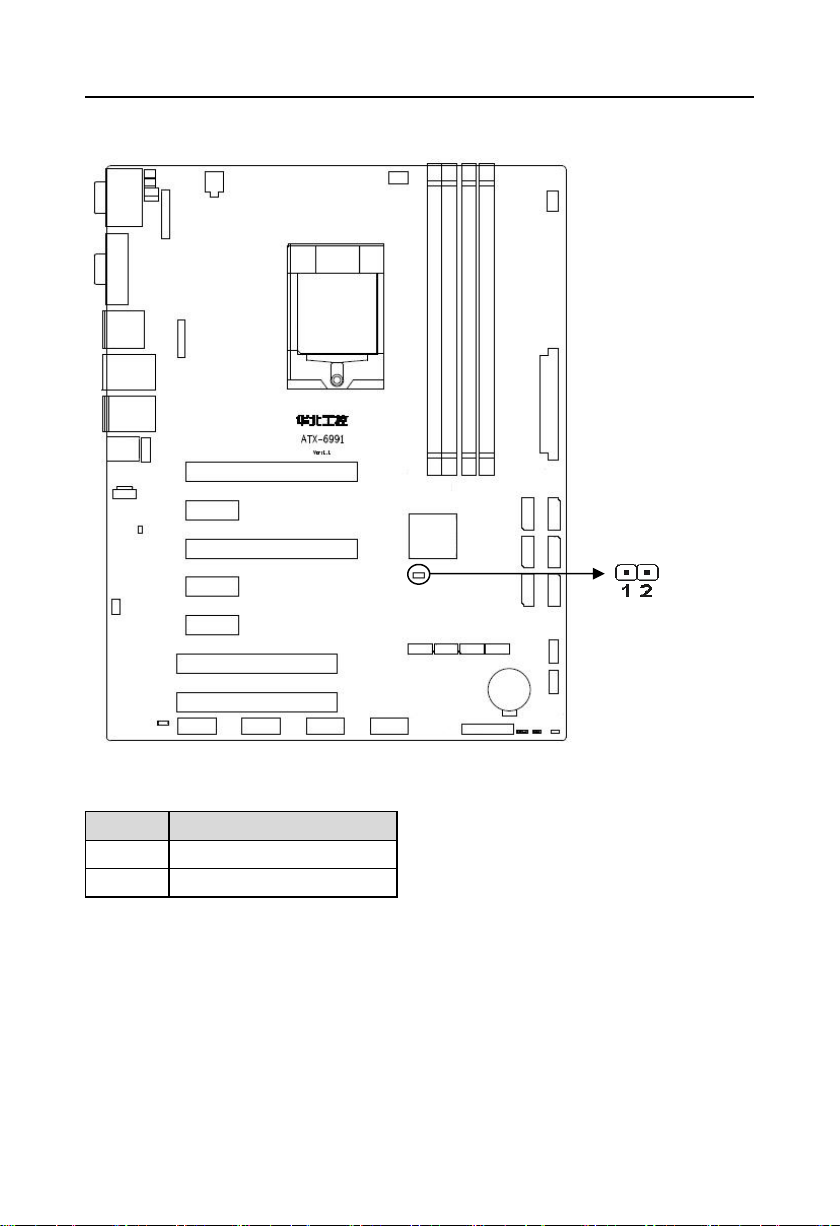
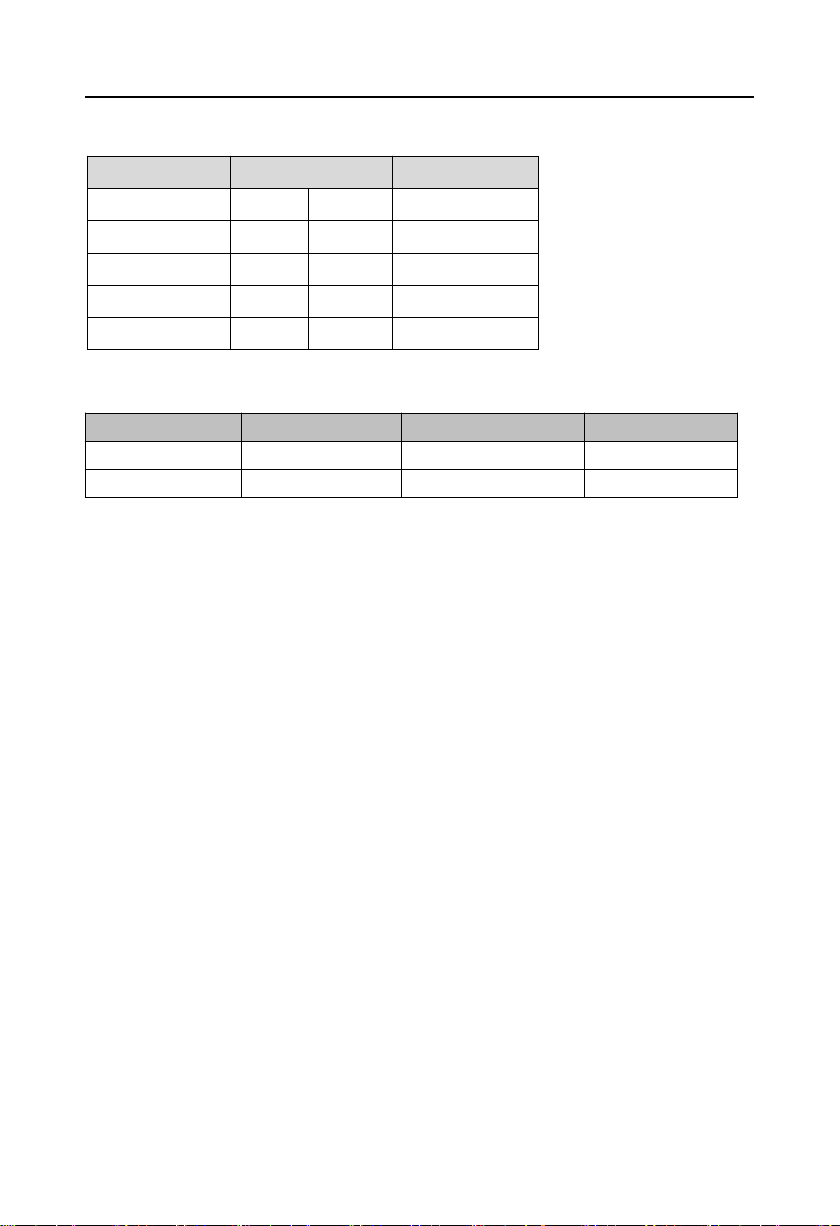
Pin
Signal Name
1
+DVDDIO_AUDIO
2
AZA_SDO
JME
2.4.3 ME Setting(JME)
JME:
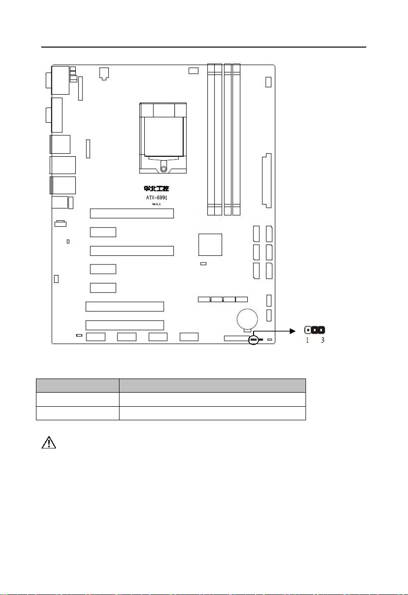
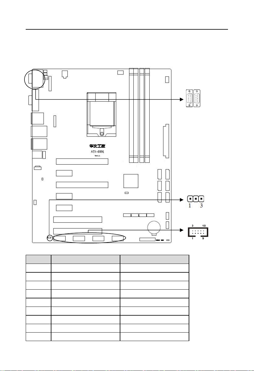
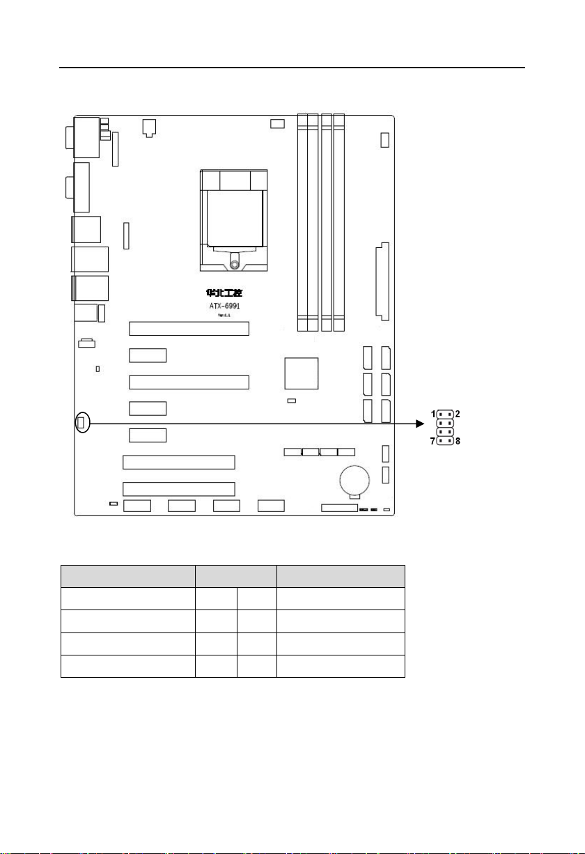
2.4.4 COM2 Jumper Setting(J1,J2,J3)
J1,2,J3 jumper is to set COM2 transmission mode,COM2 support RS232/RS422/RS485
transmission mode.
ATX-6991 User's Manual
10
COM2 AS RS232 PORT
COM2 AS RS422 PORT
COM2 AS RS485 PORT
J1
1-3 2-4
J1
3-5 4-6
J1
3-5 4-6
J2
1-3 2-4
J2
3-5 4-6
J2
3-5 4-6
J3
1-2J33-4
J3
5-6 7-8
J1、J2
J3
J1、J2、J3:
2.5 Interface specification
Please read this manual carefully before installing any external connectors, in case
of any damage to the motherboard!
2.5.1 Serial Ports(COM1,COM2,COM3-COM6,J9)
Provide 6x serial ports,COM1、COM2 are standard DB9 port,COM3-COM6 are 2.54mm
2*5 box header connector,COM1-2 support RS232/RS422/RS485 model,1x 3Pin COM port
ATX-6991 User's Manual
11
Pin
COM1
COM2
1
DCD#
DATA-
2
SIN
DATA+
3
SOUT
HSOUT2RX+
4
DTR#
HDTR#2RX
5
GND
GND
6
DSR#
DSR#
7
RTS#
RTS#
8
CTS#
CTS#
9
RI
RI
COM3-COM6
COM1、COM2
J9
power supply pin,when in use, special adapter cable is needed to supply power for COM
through COM port power supply (J9) interface.
COM1、COM2:
ATX-6991 User's Manual
12
Signal Name
Pin
Signal Name
DCD#
12DSR#
SIN
34RTS#
SOUT
56CTS#
DTR#
78RI#
GND
910COM_PIN10
Pin
Signal Name
1
+5V
2
COM_PIN10
3
+12V
SATA1-3-5
SATA2-4-6
COM3-COM6:
J9:
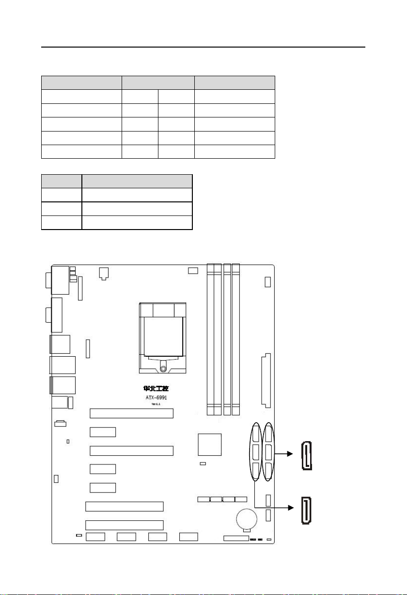
2.5.2 SATA Port(SATA1-SATA6)
Provide 6x standard 7Pin SATA port.
ATX-6991 User's Manual
13
Pin
Signal Name
1
GND
2
TX+
3
TX-
4
GND
5
RX-
6
RX+
7
GND
USB56、USB78
USB1112、USB1314
USB56_LAN2
USB34_LAN1
SATA1-SATA6:
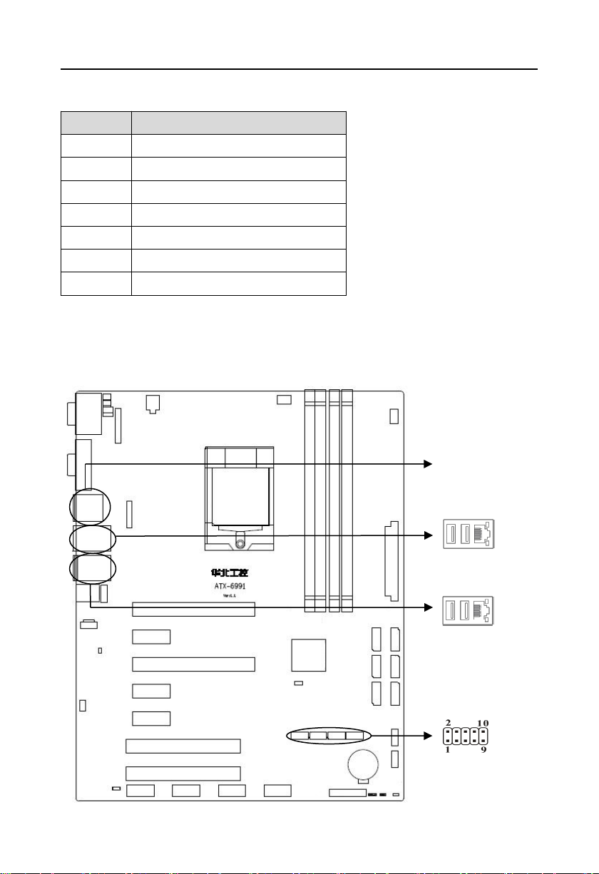
2.5.3 USB and LAN Port(HDMI_USB12,USB34_LAN1,USB56_LAN2,USB56,
USB78,USB1112,USB1314,)
Provide 14xUSB port, HDMI_USB12 、USB34_LAN1 、 USB56_LAN2 are double layer
USB3.0 port;USB56、USB78、USB1112、USB1314 port are 2×5Pin USB2.0 pin interface.
ATX-6991 User's Manual
14
Signal Name
Pin
Signal Name
VCC
12GND
USBD_N
34GND
USBD_P
56USBD_P
GND
78USBD_N
GND
910VCC
LILED(Green)
Function
ACTLED(Yellow)
Function
ON
100/1000M link
FLASH
Data transfer
OFF
10M link or close
OFF
Data stop
USB56、USB78、USB1112、USB1314:
RJ45 LAN LED status description:
ATX-6991 User's Manual
15
Signal Name
Pin
Signal Name
VCC_KM
12MS_CLK_R
GND
34MS_DATA_R
MS_DATA_R
56GND
KB_CLK_R
78VCC_KM
KM
2.5.4 Keyboard & Mouse Interface(KM)
KM:
2.5.5 Audio Interface(AUDIO,FP_AUDIO,J_SPDIFO,CD_IN)
Adopt ALC662 audio control chip,Green for audio output interface(Line-out),Pink for
microphone input interface(MIC-in).
 Loading...