

Page 1
LT2720/LT2740
Page 2
1
TABLE OF CONTENTS
INSTALLATION .......................................................................................... 1
FOR YOUR SAFETY ........................................................................ 2
IMPORTANT SAFETY INSTRUCTUONS .................................. .. 3-4
PREPARATION ............................................................................ 5-6
OPERATING INSTRUCTIONS................................................................... 7
USE OF THE REMOTE CONTROL .................................................. 7
USING THE MENUS......................................................................... 8
MAIN MENU...................................................................................... 8
CONNECT PERIPHERAL EQUIPMENT .................................................... 16
FRONT PANEL CONTROL KNOBS ................................................. 16
PREPARATION ................................................................................ 16
VIDEO RECORDER ......................................................................... 17
CAMERA, CAMCORDER, VIDEO GAME SET ................................. 18
DVD PLAYER ................................................................................... 18
DIGITAL SET TOP BOX ................................................................... 19
HEADPHONE ................................................................................... 19
TIPS .................................................................................................. 20
PRODUCT SPECIFICATION...................................................................... 22
BEFORE CALLING SERVICE.................................................................... 24
GLOSSARY ...................................................................................... 25
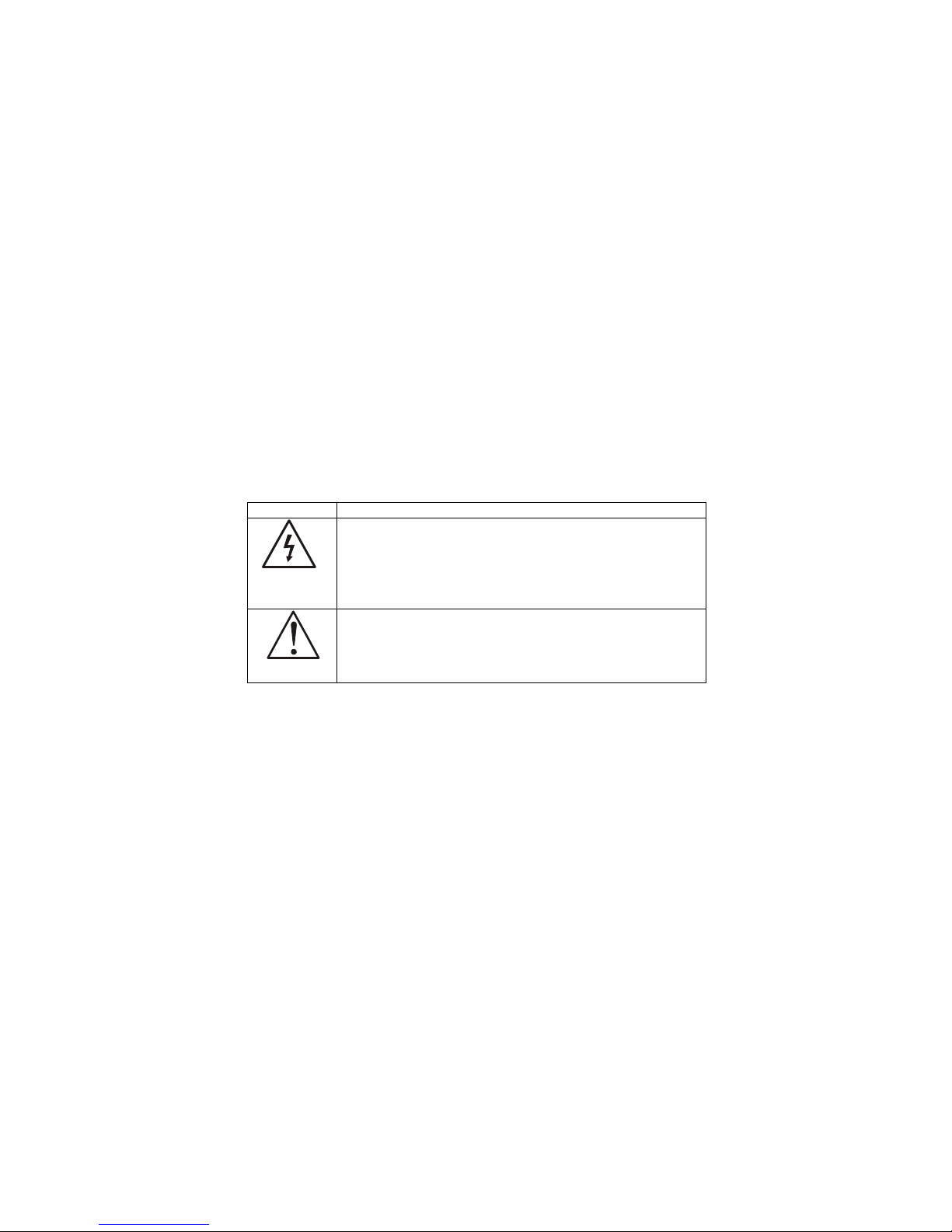
SYMBOL SYMBOL DEFINITION
SA 1965
DANGEROUS VOLTAGE: The lightning flash with
arrowhead symbol,within an equilateral triangle,is intended
to alert the user to the presence of uninsulated “dangerous
voltage”within the product’s enclosure that may be of
sufficient magnitude to constitute a risk of electrical shock to
persons.
SA 1966
INSTRUCTIONS: The exclamation point within on
equilateral triangle to alert the User to the presence of
important operating and maintenance (servicing)instruction
In the literature accompanying the appliance.
Apparatus shall not be exposed to dripping or splashing and no objects
filled with liquids, Such as vases, Shall be placed on the apparatus.
Page 3
2
FOR YOUR SAFETY
Before operating the TV please read this manual thoroughly. This manual
should be retained for future reference。
FCC Class B Radio Frequency Interference Statement
WARNING: (FOR FCC CERTIFIED MODELS))
NOTE: This equipment has been tested and found to comply with the limits
for a Class B digital device, pursuant to Part 15 of the FCC Rules. These
limits are designed to provide reasonable protection against harmful
interference in a residential installation. This equipment generates, uses and
can radiate radio frequency energy, and if not installed and used in
accordance with the instructions, may cause harmful interference to radio
communications. However, there is no guarantee that interference will not
occur in a particular installation. If this equipment does cause harmful
interference to radio or television reception, which can be determined by
turning the equipment off and on, the user is encouraged to try to correct the
interference by one or more of the following measures:
1. Reorient or relocate the receiving antenna.
2. Increase the separation between the equipment and receiver.
3. Connect the equipment into an outlet on a circuit different from that to
which the receiver is connected.
4. Consult the dealer or an experienced radio/TV technician for help.
NOTICE
1. The changes or modifications not expressly approved by the party
responsible for compliance could void the user's authority to operate the
equipment.
2. Shielded interface cables and AC power cord, if any, must be used in
order to comply with the emission limits.
W
To prevent fire or shock hazard, do not expose the TV to rain or moisture.
Dangerously high voltages are present inside the TV. Do not open the
cabinet. Refer servicing to qualified personnel only.
SRS, SRS and
are registered trademarks of SRS Labs, Inc.
This product is designed using SRS technology with permission from
SRS Labs, Inc.
Page 4

3
Read before operating equipment
1. Read these instructions.
2. Keep these instructions.
3. Heed all warnings.
4. Follow all instructions.
5. Do not use this apparatus near water.
6. Clean only with a dry cloth.
7. Do not block any of the ventilation openings. Install in accordance with
the manufacturers instructions.
8. Do not install near any heat sources such as radiators, heat registers,
stoves, or other apparatus (including amplifiers) that produce heat.
9. Do not defeat the safety purpose of the polarized or grounding type plug.
A polarized plug has two blades with one wider than the other. A
grounding type plug has two blades and third grounding prong. The wide
blade or third prong is provided for your safety. When the provided plug
does not fit into your outlet, consult an electrician for replacement of the
obsolete outlet.
10. Protect the power cord from being walked on or pinched particularly at
plugs, convenience receptacles, and the point where they exit from the
apparatus.
11. Only use attachments/accessories specified by the manufacturer.
12. Use only with a cart, stand, tripod, bracket, or table specified by the
manufacturer, or sold with the apparatus. When a cart is used, use
caution when moving the cart/apparatus combination to avoid injury from
tip-over.
13. The TV should be operated only from the type of power source indicated
on the label. If you are not sure of the type of power supplied to your
home, consult your dealer or local power company.
14. Unplug this apparatus during lightning storms or when unused for long
periods of time.
15. Refer all servicing to qualified service personnel. Servicing is required
when the apparatus has been damaged in any way, such as powersupply cord or plug is damaged, liquid has been spilled or objects have
fallen into apparatus, the apparatus has been exposed to rain or
moisture, does not operate normally, or has been dropped.
16. This product may contain lead or mercury. Disposal of these materials
may be regulated due to environmental considerations. For disposal or
recycling information, please contact your local authorities or the
Electronic Industries Alliance: www.eiae.org
17. Damage Requiring Service – The appliance should be serviced by
qualified service personnel when:
IMPORTANT SAFETY INSTRUCTUONS
Page 5
4
A. The power supply cord or the plug has been damaged; or
B. Objects have fallen, or liquid has been spilled into the appliance; or
C. The appliance has been exposed to rain; or
D. The appliance does not appear to operate normally or exhibits a
marked change in performance; or
E. The appliance has been dropped, or the enclosure is damaged.
18. Tilt/Stability – All televisions must comply with recommended
international global safety standards for tilt and stability properties of its
cabinets design.
Do not compromise these design standards by applying excessive pull
force to the front, or top, of the cabinet, which could ultimately overturn
the product.
Also, do not endanger yourself, or children, by placing electronic
equipment/toys on the top of the cabinet. Such items could
unsuspectingly fall from the top of the set and cause product damage
and/or personal injury.
19. Power Lines – An outdoor antenna should be located away from power
lines.
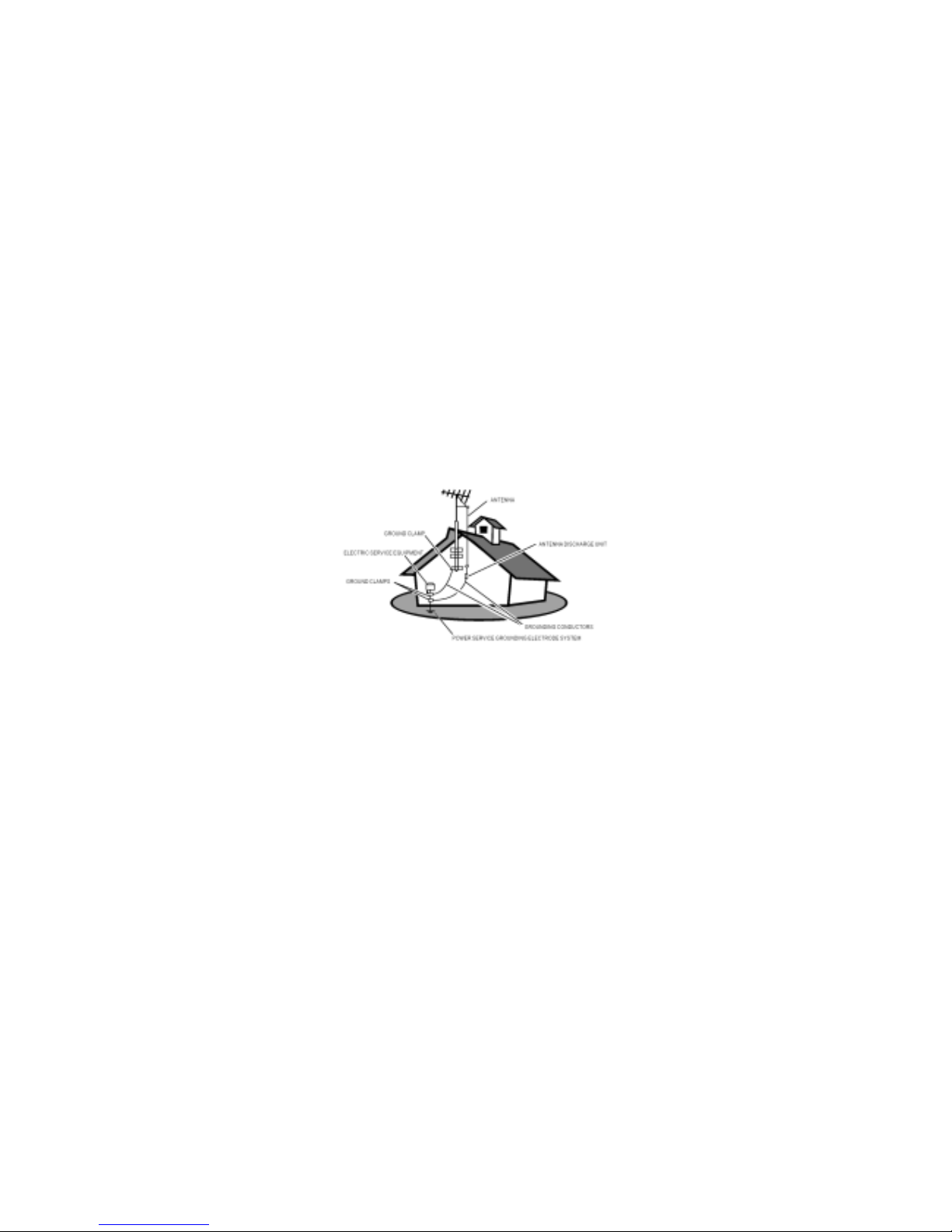
20. Outdoor Antenna Grounding – If an outside antenna is connected to
the receiver, be sure the antenna system is grounded so as to provide
some protection against voltage surges and built up static charges.
Section 810 of the National Electric Cord, ANSI/NFPA No. 70-1984,
provides information with respect to proper grounding of the mats and
supporting structure grounding of the lead-in wire to an antennadischarge unit, size of grounding connectors, location of antennadischarge unit, connection to grounding electrodes and requirements for
the grounding electrode. See Figure below.
EXAMPLE OF ANTENNA GROUNDING AS PER NATIONAL ELECTRICAL
CODE
Note to the CATV system installer: This reminder is provided to call the CATV
system installer’s attention to Article 820-40 of the NEC that provides
guidelines for proper grounding and, in particular, specifies that the cable
ground shall be connected to the grounding system of the building, as close
to the point of cable entry as practical.
21. Objects and Liquid Entry – Care should be taken so that objects do not
fall and liquids are not spilled into the enclosure through openings.
Page 6
5
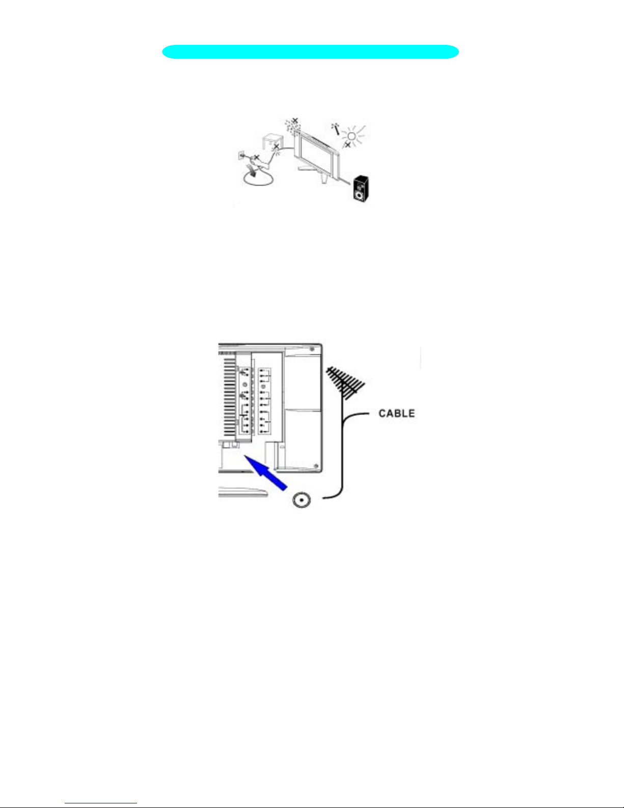
1. Place the TV on a solid surface.
Ensure that the TV is placed in a position to allow free flow of air. Do not
cover the ventilation openings on the back cover.
To prevent any unsafe situations, no naked flame sources, such as
lighted candles, should be placed on or in the vicinity.
Avoid heat, direct sunlight and exposure to rain or water. The equipment
shall not be exposed to dripping or splashing.
2. Insert the aerial plug firmly into the aerial socket ANT IN ╦ 75Ω at the
back of the TV.
PREPARATION
Page 7
6
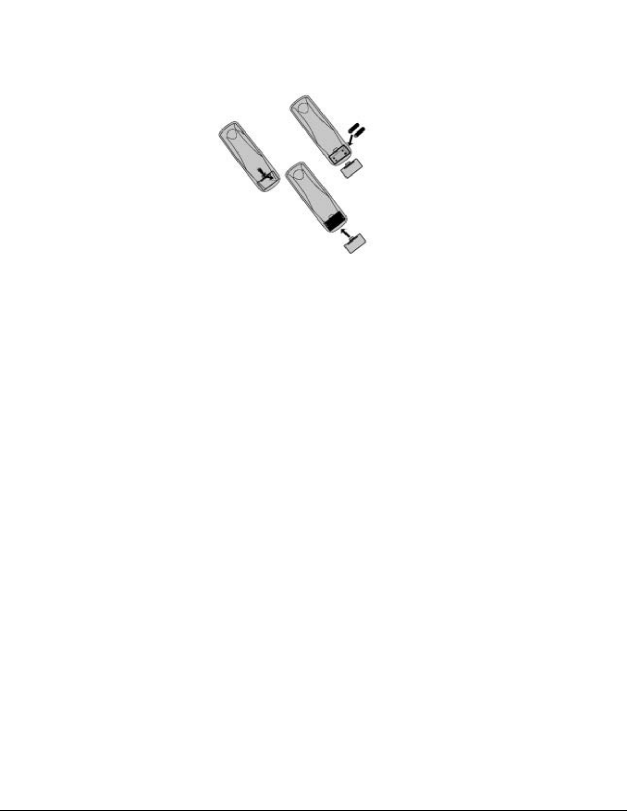
3. Remote control:
Remove the cover of the battery compartment. Insert the 2 batteries
supplied (Type AAA 1.5V).
If you intend to change the batteries on your own, please be aware of the
compatibility with the zinc carbide batteries to prevent accidents!!
4. Power:
Insert the power cord in the wall socket having an AC power supply
5. Turn the TV on:
If the TV is in power off, the indicator in front of the TV turns orange.
Press the power button at the topside of the TV to turn it on. When the
TV is ON, the indicator turns green.
Page 8
7
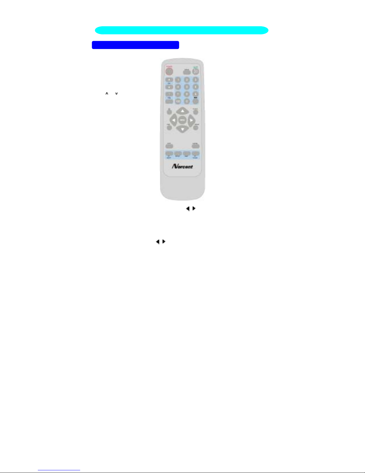
MENU, ▲, ▼, ,
These buttons are used to
display or adjust the various
functionalities.W hen the PIP
is ON but no menus are
available, use these ▲, ▼,
, to change the position
of the PIP.
USE OF THE REMOTE CONTROL
SLEEP
With this key you can set a
time period after which the
TV should switch itself to
standby. The counter runs
from 30,60,90,120 minutes.
The timer begins to count
down from the number of
minutes selected after the
display has disappeared.
POWER:
Press to turn on/off the TV.
The TV is never completely
powered off unless it is
physically unplugged.
0~9/100 Digit buttons
To select a TV channel.
TV/VIDEO
Select your input source: press
repeatedly to select TV , AV1,
AV2, S-VIDEO or
COMPONENT mode,
according to where you
connected your external
source.
AV1/AV2 for a VCR
connected to the AV
connectors of the TV.
S-VIDEO for a S-Video
VCR connected to the SVIDEO connector of the TV.
Color contrast signal and
HDTV input via Y, Pb, Pr
on the top of the DVD set.
MTS
Press this key to activate
Multichannel Television
Sound
,
Stereo or Mono
VOL
Press + or – to adjust
the volume.
MUTE
Temporarily interrupt the
sound or restore it.
CH
Press or to
browse through the
TV channels.
PRE-CH
To display the previously
selected TV channel.
SWAP
Press to swap the two
screens when PIP or
POP is work (option)
PIP
ON/OFF
Used to switch the PIP
function ON or OFF.
(option).
DISPLAY
Press this button to
Display Channel
number on the right-top
corner.
PIP/POP
Press this button to
display PC input and
other input on the
screen at same time.
(op
tion
)
.
SIZE
Display the graphic in
16:9 or 4:3 mode.
PIP
TV/VIDEO
Select the signal source:
If you are in main picture
or HDTV mode, you can
select audio1, audio2, Svideo, color contrast o
r
TV signal. Otherwise, you
can only select compute
r
graphics or HDTV.
V-CHIP
Use this button to define
the movies that this TV set
can receive.
OPERATING INSTRUCTIONS
CAPTION
Press this button to turn
Closed Caption on.
Page 9

8
OPERATIONS MENU
1. Press the MENU button to display or close the main menu.
2.
Use the cursor up/down to select a menu item.
3.
Use the cursor left/right to enter a submenu or enable/disable the
function.
4.
Press the MENU button to exit the menu.
5.
Use the instruction bar displayed under the menu to assist in the
operation of this equipment.
MAIN MENU
Press the MENU button into the main OSD (On Screen Display). Adjust item
include:
1. PICTURE PARAMETERS
2. PC PARAMETERS
3. AUDIO SETTINGS
4. PICTURE-IN-PICTURE
5. CHANNEL SETTINGS
6. PARENTAL CONTROLS
7. GENERAL SETTINGS
Page 10
9
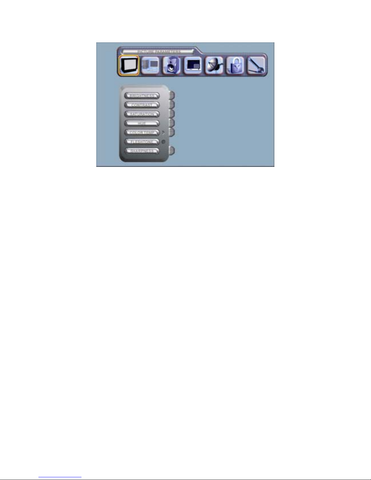
PICTURE PARAMETERS
BRIGHTNESS: Adjust the brightness of the image.
CONTRAST: Adjust the contrast of the image.
SATURATION: Adjust the depth of color of the image.
HUE: Adjust the red/green hue of the image.
COLOR TEMP:
Adjust the color temperature to your preference: 5000°,
6500°, 9300°K or select USER R, USER G,
USER B to
define your personal settings.
FLESHTONE: The flesh tone is automatically adjusted, rendering a more
natural color.
SHARPNESS: Adjust the sharpness of the video image for display
accordingly.
Page 11
10
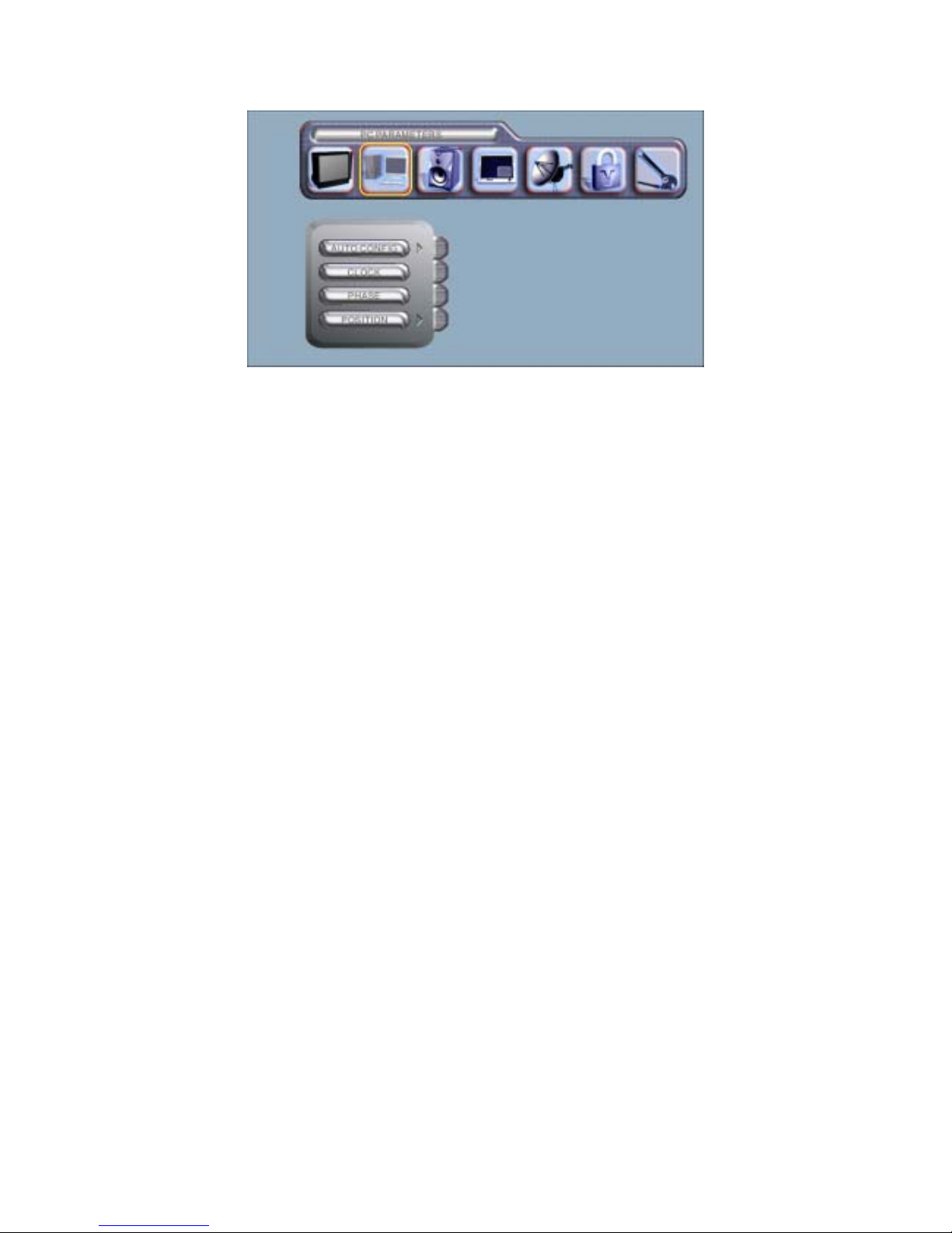
PC PARAMETERS
AUTO CONFIG: Enable the automatic configuration of the optimum size of
the graphic.
CLOCK: Adjust the time.
PHASE: Adjust the phase of the graphic.
POSITION: Adjust the position and angle of the graphic.
Page 12
11
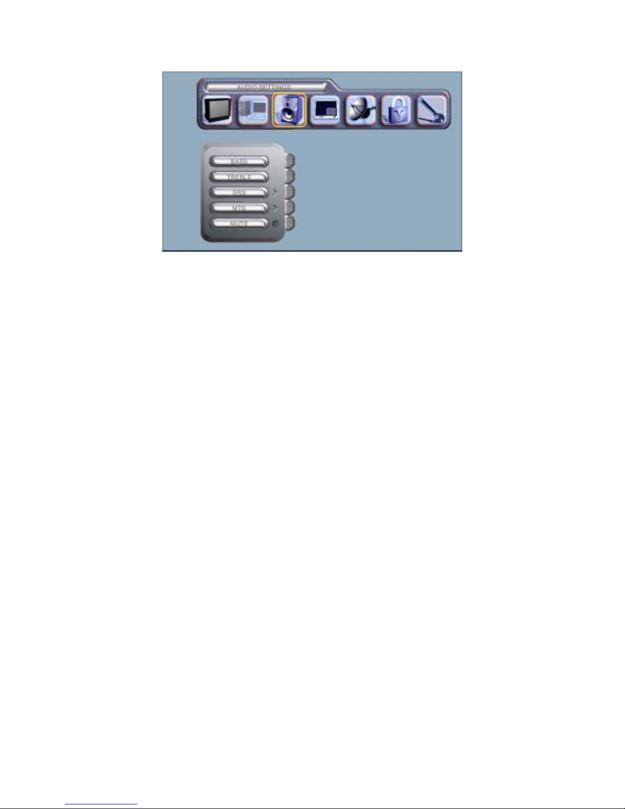
AUDIO SETTINGS
BASS: Adjust bass tone.
TREBLE: Adjust treble tone.
SRS: Switch SRS surround sound ON or OFF.
MTS: Select MONO, STEREO or SAP for bilingual setup.
MUTE: Temporarily mute the sound (can be done through remote control).
Page 13
12
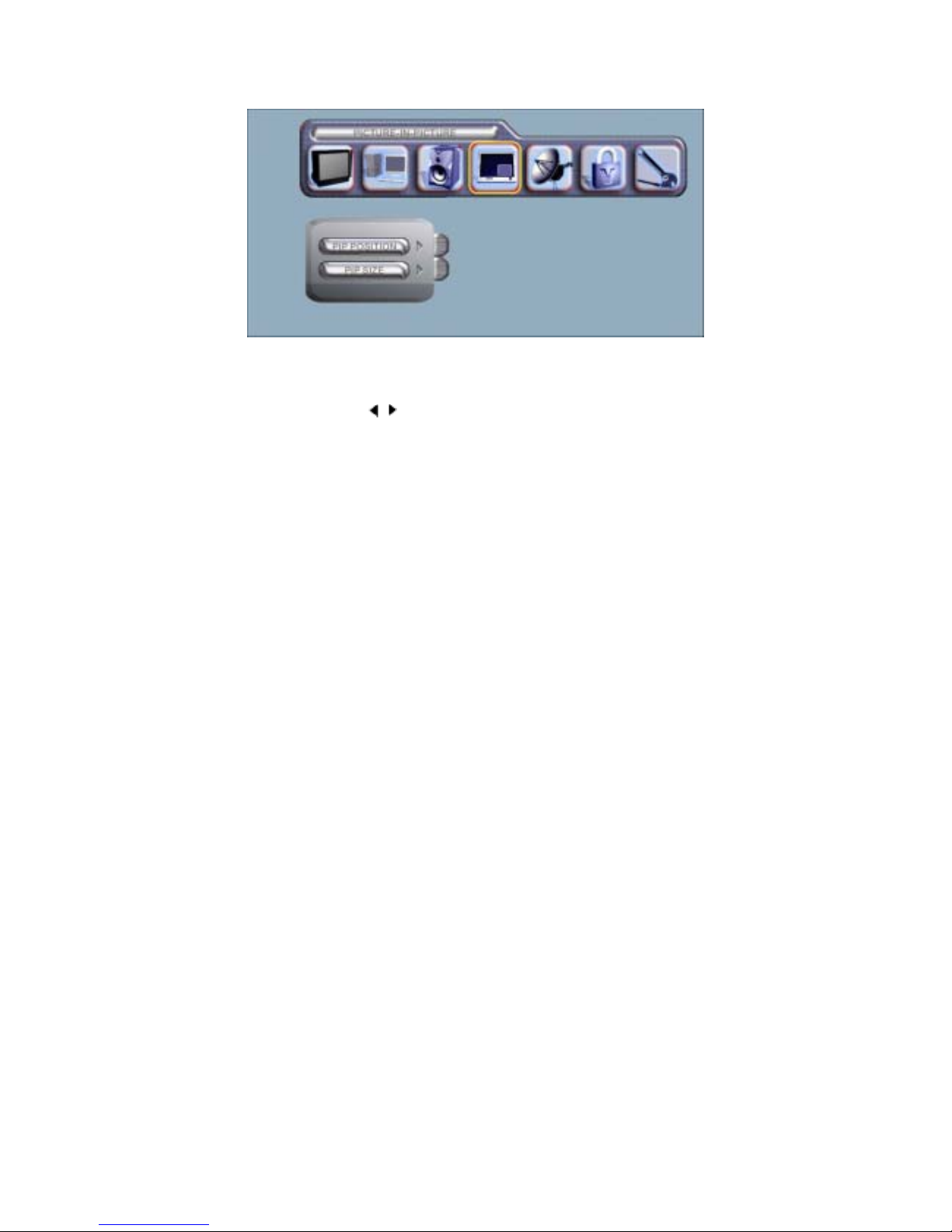
PICTURE-IN-PICTURE
PIP POSITION: The PIP can be placed in any position on the screen
according to one’s wishes. If there is no menu, use the ▲,
▼,
, buttons on the remote control to change the PIP
position.
PIP SIZE: Can be used to switch the PIP off (OFF) or select the size (SMALL,
MEDIUM, LARGE) of the PIP . Can also be used to select one of
two types (POP, PBP) of dual graphics.
Page 14
13
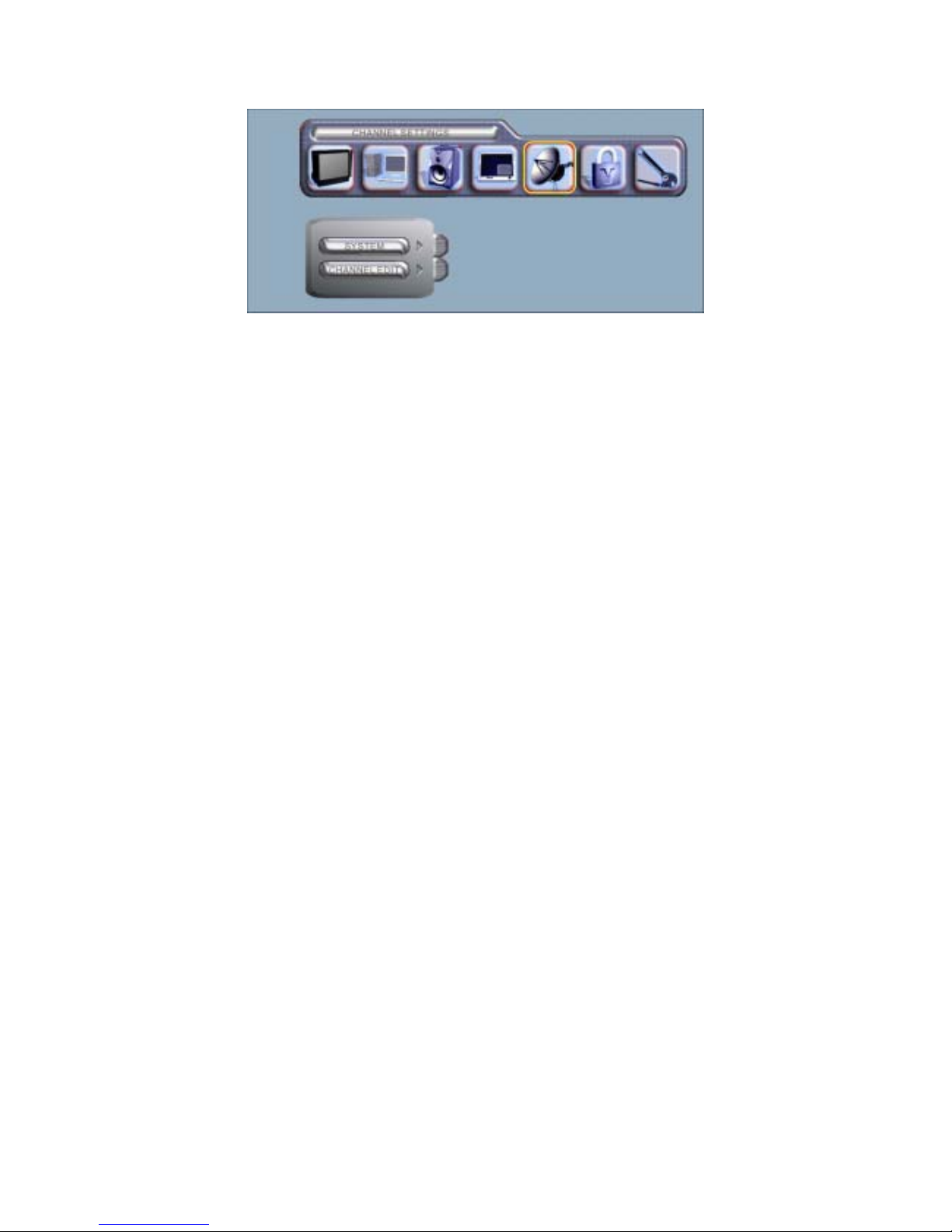
CHANNEL SETTINGS
SYSTEM: Used to choose between (ANTENNA) or (CABLE).
CHANNEL EDIT: The auto scan function searches and stores the signal of
the TV station when the YES option is selected. The ADD
or DELETE function edits the TV station signal while the
channel will be displayed if the CURRENT CH function is
selected.
Page 15
14
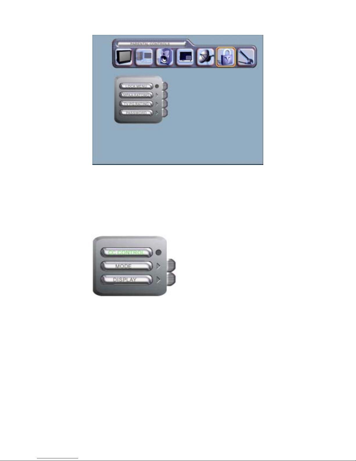
PARENTAL CONTROLS
LOCK MENU: Switch the functionality to configure ratings on or off.
MPAA RATING: Configure MPAA ratings.
TV PG RATING: Configure TVPG ratings.
PASSWORD: Change the password (default is ‘1111”). Please follow the
instructions on the screen. Once changed, please remember
your own password. If you have forgotten your password,
please do the following: “POWER (OFF) MENU V-CHIP
MUTE”to revert to the default password of 1111.
CAPTION
Press the ”CAPTION” button on
the remote to initiate the
functionality list as shown on the
left.
CC CONTROL: Switch the subtitles
function ON or
OFF.
MODE: Select mode of subtitles.
DISPLAY: S
elect display of subtitles.
Page 16
15
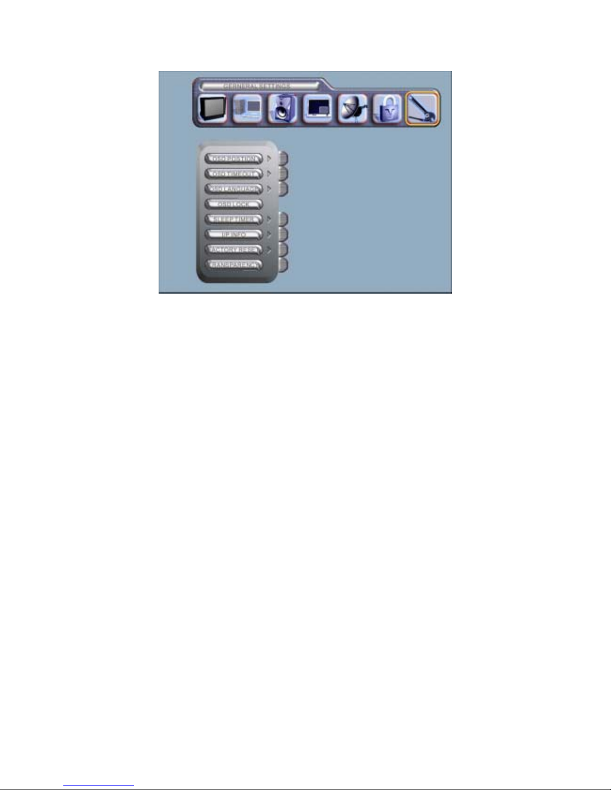
GENERAL SETTINGS
OSD POSITION: Shift the position to one’s preference.
OSD TIMEOUT: Configure the time to be displayed on screen.
OSD LANGUAGE: Configure the language (English , France or Spanish) for
the menu.
OSD LOCK: Lock the selected configurations to prevent them from being
overwritten.
SLEEP TIMER: Configure the time for sleep mode.
I/P INFO : Display the resolution and H sync, V synch for the main graphic.。
FACTORY RESET : Select YES to revert to default configurations.
TRANSPARENCY : Adjust the brightness of the background.
CONFIGURING THE TIME TO SLEEP MODE
Configure the lead time to when the television will transition to standby mode.
The timer cycle range starts from OFF→30→60→120 minutes. When the
menu disappears from the screen, the timer will start counting down from the
time set.
Note: To cancel the sleep mode, press to set the timer OFF on the SLEEP
button of the remote control. Once the television set is switched off, any
configuration that has been defined will be deleted. Please re-configure if
that happens.
Page 17
16
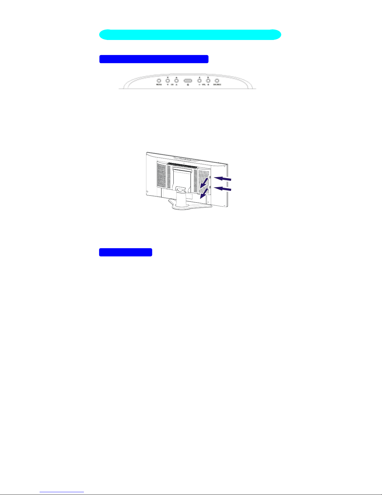
FRONT PANEL CONTROL KNOBS
Power Key: Press to turn on or off the TV.
MENU Key: Press to show the OSD menu and exit OSD menu at the TV.
Down / Up Key: Press to perform select function and channel.
- / + Key: Press to confirm your function selection and adjustment.
Source Key: Press to select your input source.
There is a wide range of video and audio equipment that can be connected to
your TV. The following connection diagrams show you how to connect them.
PREPARATION
Remove the back plate at the back of the TV as shown on the illustration
opposite.
Lay the LCD TV with the screen down on a table, as it will be easier to
connect your peripheral equipment. Please take precaution not to damage
the screen.
CONNECT PERIPHERAL EQUIPMENT
Page 18
17
VIDEO RECORDER
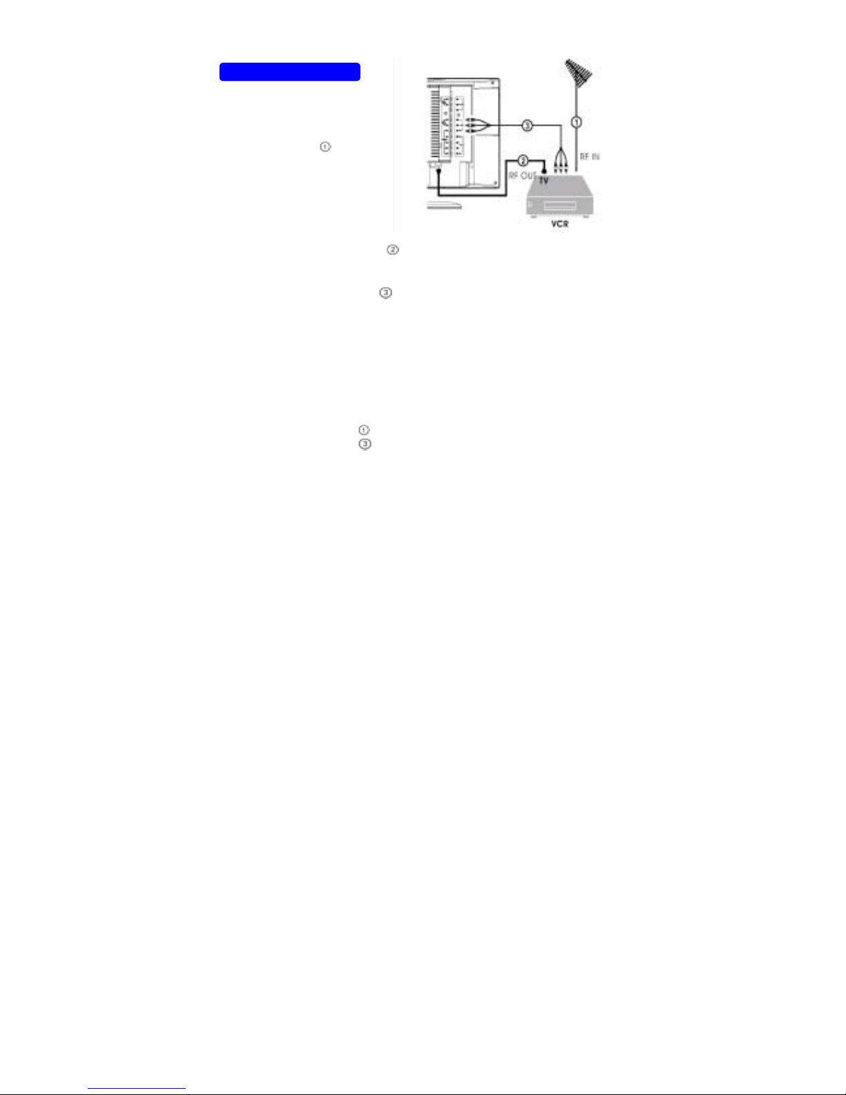
How to connect
2. Connect another RF cable
from the output RF of your VCR to the ╦
input of your TV. Better quality when playing from your VCR can be
obtained if you also connect the Video, Audio LEFT AND RIGHT (only for
stereo equipment) cables to the VIDEO, AUDIO L and R inputs AV.
If your VCR has an S-VHS video jack:
For improved picture quality, connect a S-Video cable with the S-VIDEO input
on the TV instead of connecting the VCR to the VIDEO port.
S-Video does not provide audio, audio cables must still be connected to
provide sound (AV2 and S-VIDEO use the same AUDIO INPUT).
Watching VCR
1. If you use connection
, select the TV channel 3 or 4.
2. If you use connection
, select AV1.
3. Insert videotape in the VCR and press the PLAY button.
1. Connect the supplied
antenna cable to the
RF IN port of your VCR.
Page 19
18
1. Connect the three
separate component
video cables
to the
DVD player’s Y, Pb , Pr
ports and to the Y, Pb ,
Pr ports on the TV.
CAMCORDER, VIDEO GAME SET, …
DIGITAL CAMERA
How to connect
2. For stereo equipment also connect AUDIO R
. .
S-VHS quality with an S-VHS camcorder is obtained by connecting the
S-VHS cable with the S-VIDEO input
and AUDIO input .
How to use
1. Select S-VIDEO or AV2.
2. Turn on the external AV equipment.
DVD PLAYER
How to connect
2. Connect the audio cables
to the DVD player’s AUDIO L and R ports
and to the L and R AUDIO AV ports on the TV.
How to use
1. Select COMPONENT
2. Turn on the DVD set.
1. Connect your digital
camera, camcorder,
videogame set,… to VIDEO
port
and AUDIO L for
mono equipment.
Page 20
19
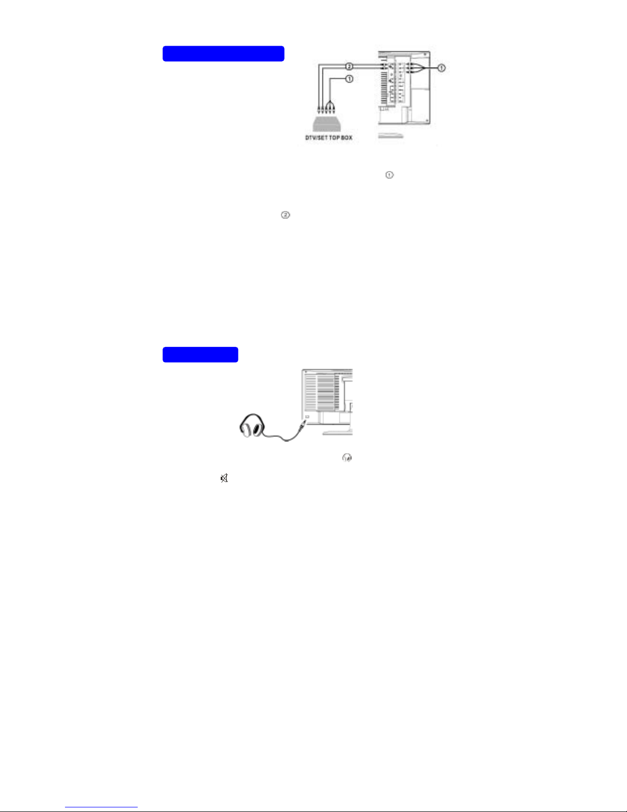
DIGITAL SET TOP BOX
How to connect
1. Connect the three separate component video cables
to the DTV/Set
Top Box’s Y, Pb , Pr ports and to the HDTV IN Y, Pb , Pr ports on the
TV.
2. Connect the audio cables
to the DTV/Set Top Box’s AUDIO L and R
ports and to the HDTV IN AUDIO L and R ports on the TV.
How to use
1. Select HDTV
2. Turn on the DTV Set Top Box set.
Warning: In case you notice scrolling images, wrong colors or no color, no
picture or even combinations of these, on your screen, check if the
connections are done in the right way. Check if the cable colors match
with the Input connector colors.
HEADPHONE
1. Insert the plug into the headphone port
, when inserting headphone
you need to block speaker audio output.
2. Press the
key on the remote control to switch off the sound from the
headphone and the internal loudspeakers of the TV.
3. Press the cursor lift/right to adjust the volume.
Note: When a TV channel or external AV source is blocked because of a
rating set via the Parental control menu, also the headphone is muted.
When you dispose of a Digital
Antenna cable connected to a
digital Set Top Box, connect the
Set Top Box to the HDTV
INPUT.
Page 21

20
TIPS
Care of the screen
Do not rub or strike the screen with anything hard as this may scratch, mar, or
damage the screen permanently.
Unplug the screen before cleaning the screen. Dust the TV by wiping the
screen and the cabinet with a soft, clean cloth. If the screen requires
additional cleaning, use a clean, damp cloth. Do not use liquid cleaners or
aerosol cleaners.
Mobile telephone warning
To avoid disturbances in picture and sound, malfunctioning of your TV or
even damage to the TV, keep away your mobile telephone from the TV.
End of life directives
We are paying a lot of attention to produce environmentally friendly in green
focal areas. Your new receiver contains materials that can be recycled and
reused.
At the end of its life specialized companies can dismantle the discarded
receiver to concentrate the reusable materials and to minimize the amount of
materials to be disposed of.
Please ensure you dispose of your old receiver according to local regulations.
Regulatory Notices – Federal Communications Commission Notice
This equipment has been tested and found to comply with the limits for a
Class B digital device, pursuant to part 15 of the FCC Rules. These limits are
designed to provide reasonable protection against harmful interference in a
residential installation. This equipment generates, uses, and can radiate radio
frequency energy and, if not installed and used in accordance with the
instructions, may cause harmful interference to radio communications.
However, there is no guarantee that interference will not occur in a particular
installation. If this equipment does cause harmful interference to radio or
television reception, which can be determined by turning the equipment off
and on, the user is encouraged to try to correct the interference by one or
more of the following measures:
Reorient or relocate the receiving antenna.
Increase the separation between the equipment and the TV.
Connect the equipment into and outlet on a circuit different from that to
which the receiver is connected.
Consult the dealer or an experienced radio or television technician for
help.
Page 22

21
Modifications –
The FCC requires the user to be notified that any changes or modifications
made to this divide that are not expressly approved by Norcent consumer
Electronics may void the user’s authority to operate the equipment.
Cables –
Connections to this device must be made with shielded cables with metallic
RF/EMI connector hoods to maintain compliance with FCC Rules and
Regulations.
Canadian notice –
This Class B digital apparatus meets all requirements of the Canadian
Interference-Causing Equipment Regulations.
Avis Canadian –
Cat apparel numerous de la classed B respected toutes les exigencies du re
glement sur le materiel brouilleur du Canada.
Page 23
22
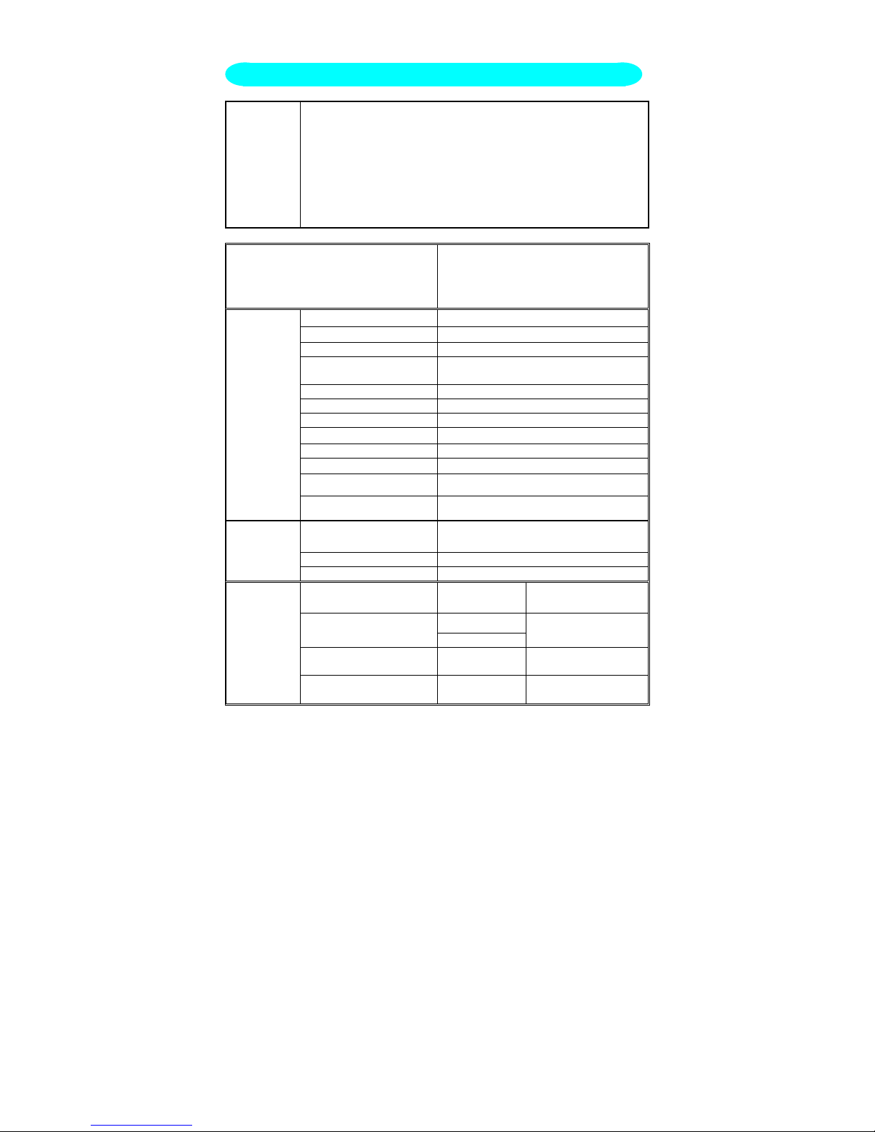
Feature 27” screen
WXGA ( 1280 x 720 ) Resolution
High Brightness ( 550 cd/m
2
)
High Contrast Ration ( 600:1 )
Wide Viewing Angle ( 170° H / 170° V )
Built-in 181 channel Tuner with MTS, SAP, Closed Caption & Vchip
PC Input
PIP/left right split window
Items
Specification
Screen Size
27” TFT-LCD Panel
Aspect Ratio
16 : 9
Resolution 1280 x 720 (WXGA)
Display Area (opening)
H x V
597.12mm x 335.88mm
Pixel Pitch 0.4665mm x 0.4665mm
Display colors 16.7 million
Contrast Ratio 600:1
Brightness
550 cd/㎡
Viewing Angle 170° (Horizontal)/ 170° (Vertical)
Response Time 16.6ms
Lamp Type/Life 14 bulb / 60000 hr
LCD Panel
Color Temperature Cool / Warm
TV Tuning System
NTSC 181 channel (PLL band)
electronic adjustment system
Sound System MTS + SAP
TV Function
Color systems NTSC
AV1 RCA x 1
Audio channel L / R
x 1
RCA x 1
AV2
S-Video x 1
Audio channelL / R
x 1(shared)
COMPONENT (color
contrast signal)
Y,Pb,Pr x 1
Audio channel L / R
x 1
Video Inputs
HDTV
(color contrast
signal)
Y,Pb,Pr x 1
Audio channel L / R
x 1
Product Specification
Page 24
23
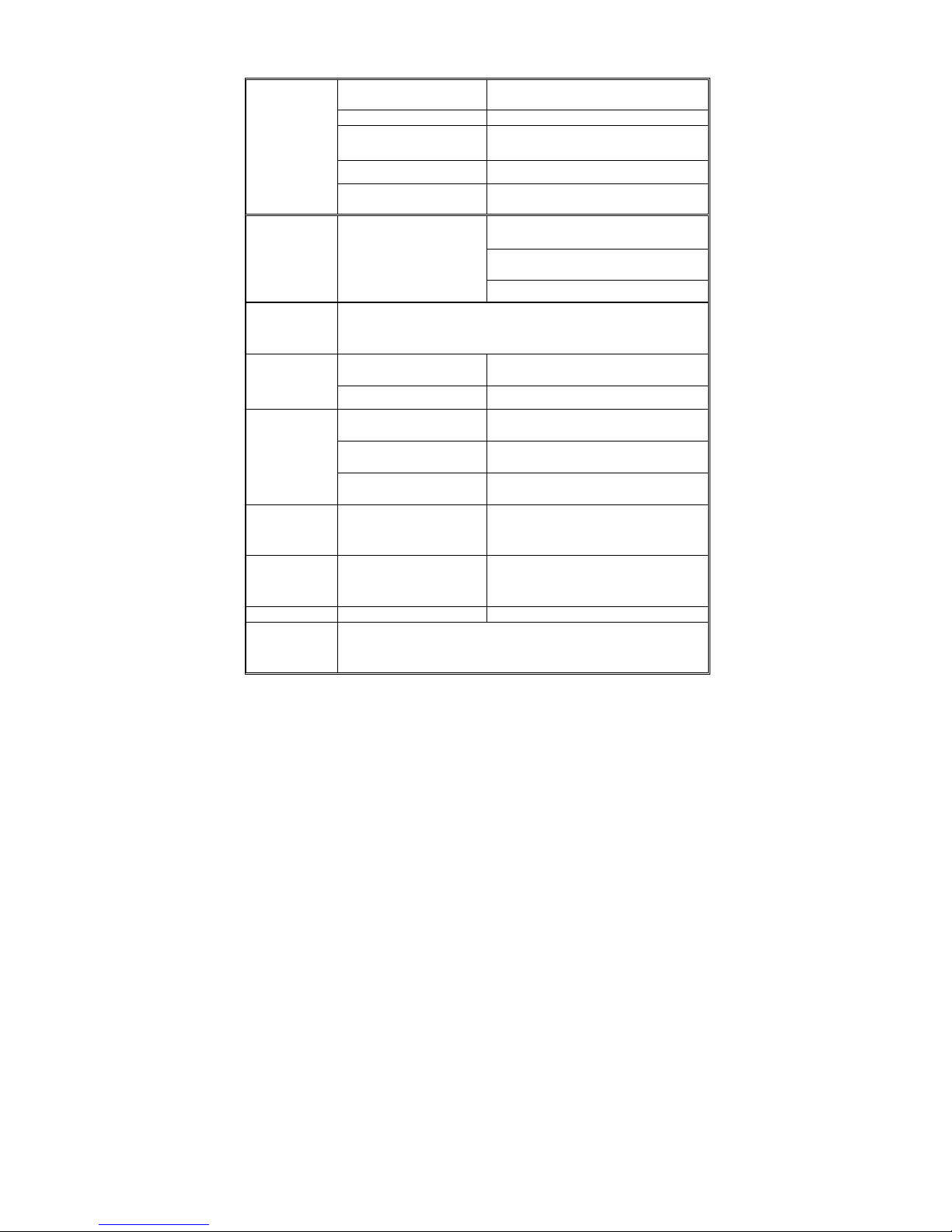
Signal Input
Analog: D-Sub 15 pin (detachable
cable)
PnP compatibility DDC / 2B
Input frequency
Analog: FH: 30KHz to 80KHz
FV: 50Hz to 75Hz
Recommended Analog:1024 x 768 (75Hz)
PC Input
Input Audio
Headphone Mini-jack for stereo
(3.5ø)
Speaker (built-in): Two 5 watt
speakers
Headphone Mini-jack for stereo
(3.5ø)
Audio Output Audio Output: L / R
Line Output (RCA L/R)
OSD language English , France or Spanish( default is English )
Power Supply AC100V~240V, 50/60Hz
Power
Power Consumption <150W
Operating temp + 0 °C ~ + 40 °C
Storage temp - 25 °C ~ + 60 °C
Environment
Operating humidity 10% ~ 85%
Panel Tilt
Forwards/Backwards/
Rotation
-5° / +20° / ±35°
Dimension W x H x D (with stand) 897.8 x 470 x 286.6 (mm)
Weight (net) Kg (w/o Accessories) 13.35 Kg
Accessories
Remote Controller, Batteries (x2), AC Power Cord, D-sub
Signal Cable, Audio line ,User’s Manual
Page 25
24
Please make these simple checks before calling for service. These tips may
save you time and money since charges for receiver installation and
adjustments of customer controls are not covered under your warranty.
Symptoms Items to Check and Actions to follow
″Ghost″ or double image *This may be caused by obstruction to
the antenna due to high rise buildings
or hills. Using a highly directional
antenna may improve the picture.
* If receiving cable TV, the weak signal
could be the result of loose cable
connections. Please contact the cable
provider to investigate.
No power *Check that the TV’s AC power cord is
plugged into the mains socket.
*Unplug the TV, wait for 60 seconds.
Then re-insert plug into the mains
socket and turn on the TV again.
No picture *Check antenna connections at the rear
of the TV to see if it is properly
connected to the TV.
*possible broadcast station trouble. Try
another channel.
*Adjust the contrast and brightness
settings.
Good picture but no sound *Increase the VOLUME.
*Check that the TV is not muted; press
the button on the remote control.
Good sound but poor color *Adjust the contrast, color and
brightness settings.
Poor picture *Sometimes, poor picture quality occurs
when having activated an A-VHS
camera or camcorder connected and
having connected another peripheral at
the same time. In this case switch off
one of the other peripherals.
Snowy picture and noise *Check the antenna connection
Horizontal dotted line *This may be caused by electrical
interference (e.g. hairdryer, nearby
neon lights, etc.)
*Turn off the equipment.
Television not responding to
remote control
*Check whether the batteries are
working. Replace if necessary
*Clean the remote control sensor lens
on the TV.
*You can still use the buttons at the front
of your TV.
Before Calling Service
Page 26

25
GLOSSARY
Audio / Video Inputs
Located on the rear and the front of the receiver these connectors (RCA
phono type plug) are used for the input of audio and video signals. Designed
for use with VCRs (or other accessories) in order to receive higher picture
resolution and offer sound connection options.
S-Video Input
Allows direct connection of high-resolution video sources, such as a Super
VHS videocassette recorder, Laser Disc player, etc. Provides improved
picture resolution, sharpness, and clarity.
COMPONENT Input
Connect directly to high resolution channels like DVD players, DTV etc
providing much improved graphics and resolution.
AUDIO OUT
Connects to external sound systems, providing audio signal output to
increase the sound quality.
Menu
An on-screen listing of feature controls shown on the TV screen that are
made available for user adjustments.
Multichannel Television sound (MTS)
The broadcast standard that allows for stereo sound to be transmitted with
the TV picture.
RF
Radio Frequency or modulated signal design used as the carrier for television
broadcasts.
Second Audio Program (SAP)
Another or additional audio channel provided for in the Multichannel
Television Sound (MTS) broadcast standard. A monaural soundtrack included
within the recorded or video signal (usually containing a second language
translation for the displayed program).
Sleep Timer
Function with which you can set a time period after which the TV should turn
itself off.
Programming
The procedure of adding or deleting channel numbers into the TV’s memory.
In this way the TV’ remembers’ only the locally available or desired channel
numbers and skips over any unwanted channel numbers.
Page 27
26
41LXXXX-815-1A
 Loading...