

Page 1
18
Alarm
Failure name Cause Corrective action
code
AL0 1 PV input failure Sensor burnout, incorrect Check the wiring.
(Over-range) wiring, incorrect PV input Set the PV input type
type setting again.
AL02 PV input failure Sensor burnout, incorrect
(Under-range) wiring, incorrect PV input
type setting
AL03 CJ failure Terminal temperature is Check the ambient
faulty (thermocouple). temperature.
PV input failure Sensor burnout, incorrect Check the wiring.
(RTD) wiring
AL 1 1 CT input failure A current exceeding the • Use a CT with the
(Over-range) upper limit of the display correct number of turns
(CT input 1 or 2, range was measured. for the display range.
or both) The number of CT turns • Reset the number of CT
or the number of CT power
turns.
wire loops is incorrectly • Reset the number of CT
set, or wiring is incorrect. power wire loops.
• Check the wiring.
AL70 A/D conversion A/D converter is faulty. Replace the unit.
failure
AL95 Parameter failure Power is shut-down while • Restart the unit.
the data is being set, or • Set the data again (set
data is corrupted by noise. data for AL95/97 and
AL96 Adjustment data Power is shut-down while
adjustment data for
failure the data is being set, or
AL96/98
.
data is corrupted by noise. • Replace the unit.
AL97 Parameter failure Data is corrupted by
(RAM area) noise.
AL98 Adjustment data Data is corrupted by
failure (RAM area) noise.
AL99 ROM failure ROM (memory) is faulty. • Reset the unit.
• Replace the unit.
Quick Reference Guide
C01 Sensor
Range
Set value
type
1K -200 to +1200°C
2K 0 to 1200°C
3K 0 to 800°C
4K 0 to 600°C
5K 0 to 400°C
6K -200 to +400°C
9J 0 to 800°C
10 J 0 to 600°C
11 J -200 to +400°C
13 E 0 to 600°C
14 T -200 to +400°C
15 R 0 to 1600°C
16 S 0 to 1600°C
17 B 0 to 1800°C
18 N 0 to 1300°C
19 PL II 0 to 1300°C
20 WRe5-26 0 to 1400°C
21 WRe5-26 0 to 2300°C
24 DIN U -200 to +400°C
25 DIN L -100 to +800°C
CP-SP-1213E
This guide offers a summary of key operations, parameter flowcharts, and settings, for
convenient reference at the operation site. This guide is made for repeated use. Dirt wipes
off easily and even notes written with an oil-based felt-tip pen can be removed with an
eraser. If more detailed information on the SDC15 is needed, refer to the user's manuals:
CP-SP-1147E for basic operation and CP-SP-1148E for installation and configuration.
The most convenient way to configure the SDC15 is with the Smart Loader Package
(model No. SLP-C35J50). Please contact Yamatake Corporation or a distributor for more
information.
[mode] key
[para] key
Lower display
Upper display
Loader connector
(bottom panel)
Mode indicators
[ ], [ ], and [ ] keys
Various indicators
Indicators during AT
PV input range table
C01 Sensor
Range
Set value
type
41 Pt100 -200 to +500°C
42 JPt100 -200 to +500°C
43 Pt100 -200 to +200°C
44 JPt100 -200 to +200°C
45 Pt100 -100 to +300°C
46 JPt100 -100 to +300°C
51 Pt100 -50.0 to +200.0°C
52 JPt100 -50.0 to +200.0°C
53 Pt100 -50.0 to +100.0°C
54 JPt100 -50.0 to +100.0°C
63 Pt100 0 to 200.0°C
64 JPt100 0 to 200.0°C
67 Pt100 0 to 500°C
68 JPt100 0 to 500°C
[Thermocouple] [RTD]
[DC voltage/DC current]
: Initial value
*1: PL II thermocouple is a range, which has been added to the units manufactured
form July, 2003.
*2: The indicated low limit for a B thermocouple is 20°C. However, if ROM version 1
of the instrument information bank (I d02) is prior to 2.04, the value is
-180°C.
*3: Thermocouple, RTD, and DC voltage/DC current are according to PV No. type.
List of alarm code
Handling precautions
• If ROM version 1 of the instrument information bank (I d02) is prior to 2.04, CT
input failure (AL 1 1) is not displayed.
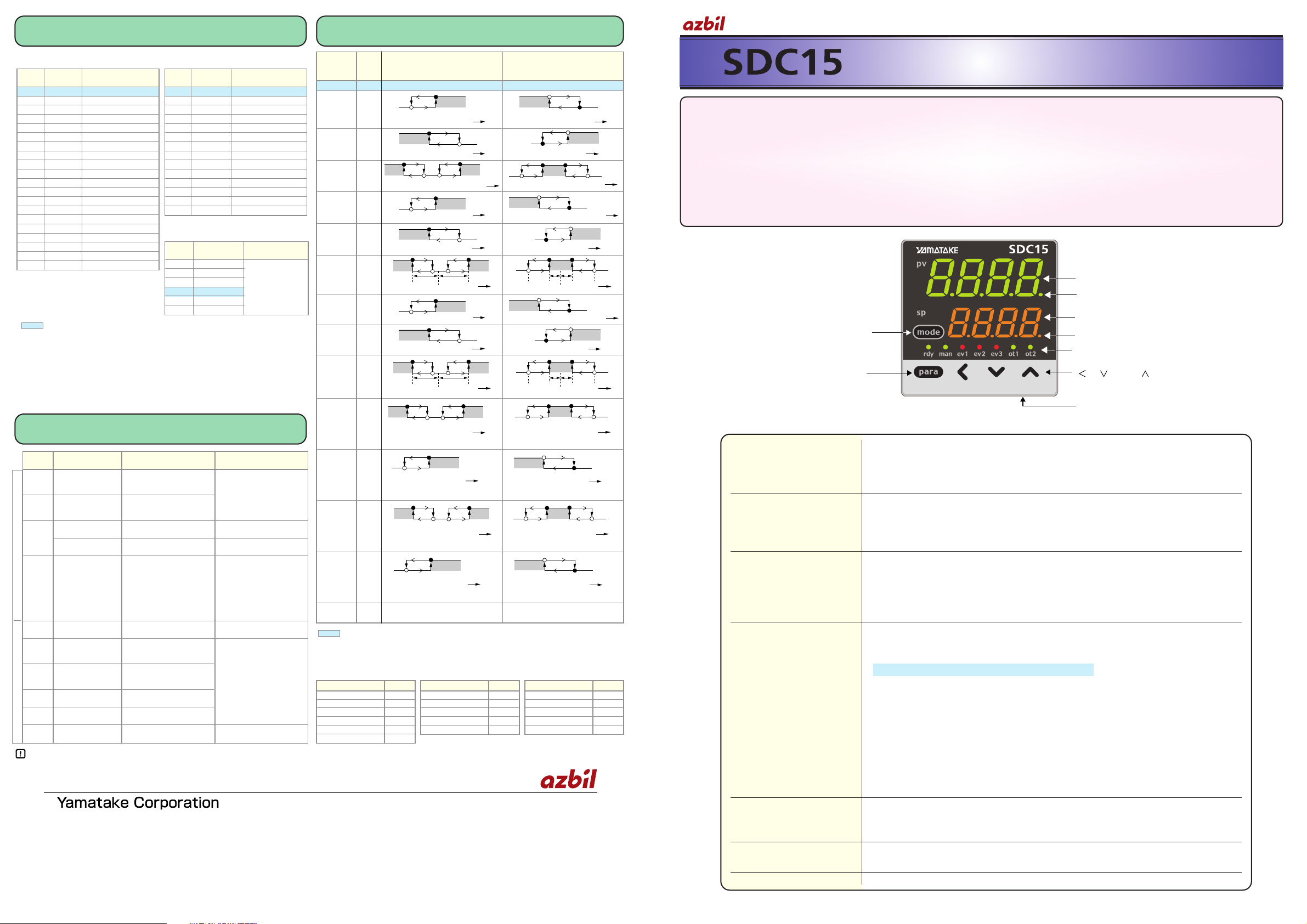
Event type
Event types other than the above:
: initial value
*: If the main setting is greater than the sub-setting, operations are performed with the main
setting and sub-setting automatically swapped.
Upper display This display shows either the PV value or the display value and set value for
each displayed item. If an alarm is triggered, the normal display and alarm
code are displayed alternately. During auto tuning (AT), the rightmost decimal
point flashes twice repeatedly.
Lower display This display shows either the SP/MV/CT or the display value and set value
for each displayed item. The rightmost decimal point lights up or flashes
to show RUN/READY mode or communications status, depending on the
setting.
Mode indicators rdy: Lights when READY (RUN mode if not lit)
man: Lights when MANUAL (AUTO mode if not lit)
ev1, ev2, ev3: Lights when event relays are ON
ot1, ot2: Lights when the control output is ON (always lit when the
current output is used)
[mode] key • When this key is pressed and held for more than 1 second in the operation
display mode, any of the following operations from 0 to 7 which have been
set previously can be executed:
0 : Mode key does not operate (Initial value)
1 : AUTO/MANUAL mode selection
2 : RUN/READY mode selection
3 : AT (Auto Tuning) start/stop selection
4 : LSP (Local SP) group selection
5 : Release all DO (Digital Output) latches
6 : Mode key does not operate
7 : ON/OFF selection of communication DI
• When pressing the [mode] key in the setup display mode, the display is
changed to the operation display
[para] key • This key is used to change the display item.
• When this key is kept pressed for 2 sec. or longer in the operation display
mode, the display is then changed to the setup display
[<], [ ], [ ] keys Theses keys are used to increase or decrease the numeric value, or to shift
the digit.
Loader connector The Smart Loader connector is on the bottom of the SDC15.
C01 Sensor
Range
Set value
type
84 0 to 1V Scaling range is
86 1 to 5V -1999 to +9999.
87 0 to 5V
88 0 to 10V
89 0 to 20mA
90 4 to 20mA
Operation type Set value
SP high limit 10
SP low limit 11
SP high/low limit 12
MV high limit 13
MV low limit 14
MV high/low limit 15
Operation type Set value
Loop diagnosis 1 20
Loop diagnosis 2 21
Loop diagnosis 3 22
READY (status) 24
MANUAL (status) 25
Operation type Set value
During AT (status) 27
During SP ramp 28
Control action (status) 29
ST setting standby (status)
30
Timer (status) 32
Specifications are subject to change without notice.
Advanced Automation Company
1-12-2 Kawana, Fujisawa
Kanagawa 251-8522 Japan
URL: http://www.azbil.com
Printed on recycled paper. (07)
Printed in Japan.
1st Edition: Issued in Mar. 2007 (W)
Operation
Set Direct action Reverse action
type
value
No event 0 Always OFF Always OFF
PV high 1
limit
PV low 2
limit
PV high/ 3
low limit
Deviation 4
high limit
Deviation 5
low limit
Deviation 6
high/low
limit
Deviation 7
high limit
(Final SP
reference)
Deviation 8
low limit
(Final SP
reference)
Deviation 9
high/low
limit
(Final SP
reference)
Heater 1 16
burnout/
Overcurrent
Heater 1 17
shortcircuit
Heater 2 18
burnout/
Overcurrent
Heater 2 19
shortcircuit
Alarm 23
ON if alarm occurs (alarm code AL01 to 99). OFF if alarm occurs (alarm code AL01 to 99).
(status)
OFF in other cases. ON in other cases.
●
shows that the ON/OFF is changed at this value.
O
shows that the ON/OFF is changed at a point that
"1U" is added to this value.
●
shows that the ON/OFF is changed at this value.
O
shows that the ON/OFF is changed at a point that
"1U" is added to this value.
Main setting
PV
ON
HYS
Main setting * Sub-setting *
PV
ON
HYS
ONHYS
Mainsetting* Sub-setting*
PV
ONHYS
HYS
ONHYS
SP + Main setting
PV
ON
HYS
SP + Main setting
PV
SP + Main setting
PV
ON
HYS
SP + Main setting
PV
ONHYS
Main setting
Sub-setting
PV
SP
ON
HYS
ONHYS
ONHYS
HYS
Main setting
Sub-setting
SP PV
ONHYS
SP + Main setting
PV
ON
HYS
SP + Main setting
PV
SP + Main setting
PV
ON
HYS
SP + Main setting
PV
ONHYS
Main setting
Sub-setting
PV
SP
ON
HYS
ONHYS
ONHYS
HYS
Main setting
Sub-setting
SP PV
Main setting *
Sub-setting *
CT1 at output ON
ON
HYS
ONHYS
OFF before measuring the CT1 current value
CT1 at output ON
ONHYS
HYS
Main setting * Sub-setting *
OFF before measuring CT1 current value
ONHYS
Main setting
PV
ON
HYS
Main setting
PV
Main setitng *
Sub-setting *
CT2 at output ON
ON
HYS
ONHYS
OFF before measuring CT2 current value
CT2 at output ON
ONHYS
HYS
Main setting *
Sub-setting *
OFF before measuirng CT2 current value
ONHYS
Main setting
CT2 at output OFF
OFF before measuring CT2 current value
ON
HYS
Main setting
CT2 at output OFF
OFF before measuring CT2 current value
ONHYS
Main setting
CT1 at output OFF
OFF before measuring CT1 current value
ON
HYS
Main setting
CT1 at output OFF
OFF before measuring CT1 current value
Main setting
PV
ONHYS
<
<
Input failureUnit failure
Page 2
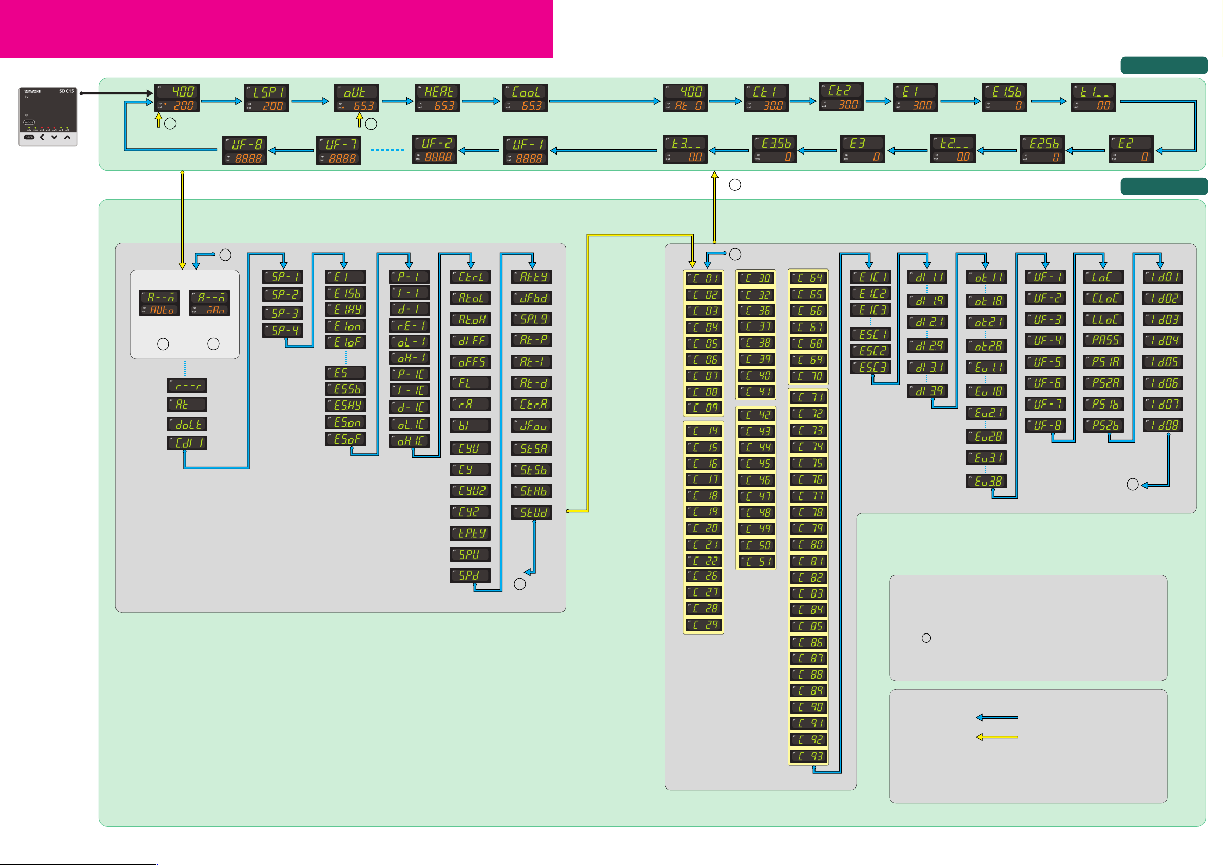
32
Flowchart of key operations and displays
[para] key
2-secondpress
+holdof
[para]key
2-second press
+ hold of
[para] key
2-second
press + hold
of [para] key
[para] key
When the power
is turned ON
[para] key
[para] key
B
[para]
key
B
1
2
A
A
2
For change
from MANUAL
to AUTO
For change
from AUTO
to MANUAL
1
2
(3)
(3)
(1)
(2)
to
to
to to
to
Upper and lower displays
remain off for 6s after
power ON. Each mode
indicator lights sequentially,
and then the operation
display appears.
PV value LSP group
number
SP value SP value
Setting value
Internal event 3
delay time
Internal event 3
sub setting
Setting value Setting value Setting value
Internal event 3
main setting
Timer remaining
time 3
Internal event 2
delay time
Timer remaining
time 2
Internal event 1
delay time
Timer remaining
time
Internal event 2
sub setting
Internal event 2
main setting
Internal event 1
main setting
Setting value
Setting value
Internal event 1
sub setting
Manipulated
variable
MV value MV value MV value AT progress
value
PV value
Current
value
CT1
Current
value
CT2
Heat manipulated
variable
Cool manipulated
variable
Analog input
SP
Notes:
(1)
The parameters and numerical values registered as user functions
UF
are displayed.
(2)
If no key is pressed for 3 minutes, the display automatically returns
to 2 , PV display.
(3)
If the [<] key is pressed while holding down the [para] key, various
displys/settings can be navigated in reverse order.
■ Explanation of arrows
[para] key :
2-second press
+ hold of :
[para] key
■ Movement through each setup menu
• [para] key Forward movement
• [para] key + [<] key Backward movement
(AUTO)
(MANUAL)
Communications
Control actions
Continuous outputs
Key operations and displays
[mode]
[SP] [
Event
][
PID
][
Parameter
][
Extended tuning
][
Setup
]
[Event configuration]
[DI assignment]
[
DO assignment
]
[User function]
[
Lock][Instrument information
]
Operation displays
Setting displays
O Some items are not displayed depending on the availability of optional functions, model number, display setup
(
C73
to
C78
) and display level (
C79
).
O Pressing [para] while changing settings has the effect of canceling and moving to the next item.
Page 3

54
Operation examples
Setup of
PV input range type
Start from the
operation display
(if necessary
press [mode] once
to get the operation display).
Press and hold
[para] for more
than 2s to get the
parameter setup
display.
a--M
is
shown on the
upper display.
Press and hold
[para] for more
than 2s again to
get the setup
setting display.
The current set
value for
C01
(PV input range
type) is displayed.
When the [<], [ ]
or [ ] key is
pressed, the rightmost digit on the
lower display
flashes. If no key
is pressed for
more than 2s after
changing to the
desired value in
the PV input range
list, the display
changes from
flashing to continuously lit, and
the displayed
value is now set.
<
<
If no sensor is connected,
an alarm for abnormal
PV input (any one from
AL01
to
AL11
) may
appear on the upper
display.
In case of ON/OFF
control,
r--r
appears
on the upper display.
Setup of
event
operation type
Start from the
operation display
(if necessary
press [mode]
once to get the
operation display).
Press and hold
[para] for more
than 2s to get the
parameter setup
display.
a--M
is
shown on the
upper display.
Press and hold
[para] for more
than 2s again to
get the setup
setting display.
The current set
value for
C01
(PV input range
type) is displayed.
Press [para]
repeatedly to get
e1.c1
on the upper
display. 0 is
displayed on the
lower display.
In this example, the event 1 operation type is set to
deviation high limit.
Similarly, use
e2.C1
to set the event 2 operation type, and
use
e3.C1
for event 3.
When the [ ] or [ ] key is pressed, the rightmost
digit on the lower display flashes. Change the
flashing digit to
4
by pressing [ ] or [ ].
If no key is pressed for more than 2s, the
displayed value is set and the display changes
from flashing to continuously lit.
<
<
<
<
4
on the lower display indicates that the event operation type is
set for deviation high limit.
0
on the lower display
indicates that the event
operation type is set to
"none."
Execution of
auto tuning
(AT)
Start from the
operation display
(if necessary
press [mode]
once to get the
operation display).
Press and hold
[para] for more
than 2s to get the
parameter setup
display.
a--M
is
shown on the
upper display.
Press [para] twice.
The upper display
says
at
and the
lower display says
at.Of
.
When [ ] or [ ] is
pressed,
at.Of
flashes.
If no key is pressed
for more than 2s,
at.ON remains steadi-
ly lit and AT begins.
During AT, the rightmost decimal point
flashes twice repeatedly. (When AT
is done, the light
goes off and the
new PID values go
into effect.)
[
Press [ ] once.
The lower display
starts to flash
at.On
.
AT forces ON/OFF of the MV a number of times (a limit
cycle) to calculate PID values.
Check that this operation does not create any problems
for the associated equipment before executing AT.
During the AT process, if the mode is changed to
READY or MANUAL, if PV input is faulty, or if a power
failure occurs, AT stops automatically without changing
the PID values.
AT can also be stopped by changing the setting from
At.ON
to
At.OF
(return to step 3 above).
<
<
<
If the control method is
ON/OFF control and if
Bit 3 (AT stop/start
display) of the mode
display setting (C73) is
set to "disabled: 0,"
nothing is displayed.
Flashing occurs only in
RUN and AUTO modes,
if there is no PV input
abnormality.
Also, if "AT stop/start" is
selected for DI assignment, the display does
not blink and no change
can be made.
Setup of
SP value
Start from the
operation display
(if necessary
press [mode] once
to get the operation display).
Check that the
operation display
is displaying the
SP.
(If not, press [para]
repeatedly until the
SP is displayed.)
When the [<], [ ]
or [ ] key is pressed, the rightmost
digit on the lower
display flashes and
the SP can be
changed to the
desired value.
In this case, the
flashing of the
numerical value
implies that it is not
yet set. A numerical
setting that is being
changed flashes
the same way.
If no key is pressed
for more than 2s,
the displayed value
is set and the
display changes
from flashing to
continuously lit.
<
<
If the [mode] key is
pressed when the
display is flashing, the
status returns to that of
step 1.
If an SP limit is in effect, the numerical
value cannot be changed to a value
above the limit. The SP limit must be
changed first.
Green letters
: Items before operation
Blue letters
: Items during operation
Start from the
operation display
(if necessary press
[mode] once to get
the operation
display).
Press and hold
[para] for more
than 2s to get the
parameter setup
display.
a--M
is
shown on the
upper display.
Press the [para]
key once. The
upper display says
r--r and the lower
display says
rdy
(or
run
).
When [ ] or [ ] is
pressed, the lower
display flashes.
If no key is pressed
for more than 2s,
the displayed value
is set and the
display changes
from flashing to
continuously lit.
When [ ] or [ ] is
pressed,
run
(or
rdy
) on the lower
display flashes.
>
>
>
>
The current mode is
indicated by
run
for
RUN mode or
rdy
for
READY mode.
In case of ON/OFF
control,
r--r
appears
on the upper display.
If the DI assignment is
set to "RUN/READY
selection," the display
does not flash and no
change can be made.
RUN/READY
mode selection
Setup of PID value
Setup of
event value
Start from the
operation display
(if necessary press
[mode] once to
get the operation
display).
Press and hold
[para] for more
than 2s to get the
parameter setup
display.
a--M
is
shown on the
upper display.
Press [para]
repeatedly to get
p-1
(for proportional band) on
the upper display.
The value set for
p-1
is displayed on
the lower display.
When [<], [ ] or
[ ] is pressed, the
rightmost digit on
the lower display
flashes, and can
be changed to the
desired value for
the proportional
band.
In this case, the
flashing of the
numerical value
implies that it is
not yet set. A
numerical setting
that is being
changed flashes
the same way.
Similarly, use
i-1
to set the integral time (0 to 9999s),
and
d-1
to set the derivative time (0 to 9999s).
>
>
If the control method is
"ON/OFF control,"
nothing is displayed.
The proportional band
can be set in a range
from 0.1 to 999.9%.
If no key is pressed for more than 2s, the
displayed value is set and the display changes
from flashing to continuously lit.
If the [mode] key is pressed when the display is flashing, the status
returns to that of step 1.
Start from the
operation display
(
if necessary press
[mode]
once to get
the operation
display).
Press and hold
[para] for more
than 2s to get the
parameter setup
display.
a--M
is
shown on the
upper display.
Press [para]
repeatedly to get
e 1
on the upper
display. The lower
display says 0.
When [<], [ ] or
[ ] is pressed, the
rightmost digit on
the lower display
flashes, and can
be changed to the
desired value for
the event.
In this case, the
flashing of the
numerical value
implies that it is
not yet set.
A numerical setting that is being
changed flashes
the same way.
To set hysteresis
as well, press
[para] once (or
twice, depending
on the settings) to
display
e 1.hy
on
the upper display.
The lower display
says 5.
When [<], [ ] or
[ ] is pressed, the
rightmost digit on
the lower display
flashes, and can
be changed to the
desired value for
hysteresis.
If no key is pressed
for more than 2s,
the displayed value
is set and the
display changes
from flashing to
continuously lit.
Similarly, use
e2
to set a value for event 2, and e3 to set
a value for event 3.
Similarly, use
e2.hy
to set a hysteresis value for event 2,
and
e3.hy
to set a hysteresis value for event 3.
>
>
<
<
0
on the lower display
indicates that the event
main set value is "zero."
5
on the lower display
indicates that the current
set value for event
hysteresis is 5.
If no key is pressed for more than 2s, the displayed
value is set and the display changes from flashing
to continuously lit.
If the [mode] key is pressed when the display is flashing, the status
returns to that of step 1.
Memo
• For step numbers indicated in red like
, the following precaution applies:
If the key lock is set, the numerical value does not flash, and the value cannot be changed.
To change a numerical value, cancel the key lock first.
Page 4

6
[Mode bank]
List of parameter
List of operation displays
List of parameter setting displays
Display Item Contents Initial value
Setting value
A--M AUTO/MANUAL AUTO: AUTO mode MAN: MANUAL mode AUTO
r--r RUN/READY RUN: RUN mode RDY: READY mode RUN
At AT stop/start At. OF: AT stop At. ON: AT start AT stop
do Lt Release all DO latches Lt. ON:
Latch continue
Lt. OF:
Latch release Latch continue
C. dI 1 Communication DI1 dI.OF: OFF dI.On: ON OFF
*1 0: Unit of "1s" 1: Fixed at 0.5s 2: Fixed at 0.2s 3: Fixed at 0.1s
*2 5 to 120s when output includes the relay output
: Essential parameters for PV measurement and control
: Basic parameters
: Required parameters when using optional functions
[Extended tuning bank]
*1 Normal = Standard control characteristics, Immediate response = Control characteristics that respond immedi-
ately to external disturbance, Stable = Control characteristics having less up/down fluctuation of PV
[Setup bank]
List of setup setting displays
Display Item Contents
Initial value
Setting value
At.ty AT type
0: Normal 1: Immediate response 2: Stable
*1 1
JF.bd ● Just-FiTTER setting band 0.00 to 10.00 0.30
SP.LG ● SP lag constant 0.0 to 999.9 0.0
At-P ●
Proportional band tuning factor at AT
0.00 to 99.99 1.00
At-I ● Integral time adjust at AT 0.00 to 99.99 1.00
At-d ● AT Derivative time adjust 0.00 to 99.99 1.00
Ctr.A Control algorithm
0: PID(Conventional PID)
0
1: Ra-PID(High-performance PID)
JF.Ov
Just-FiTTER oversheet suppression factor
0 to 100 0
St.SA ●
ST step execution resolution band
0.0 to 99.99 10.0
St.Sb ● ST step setting band 0.0 to 10.00 0.50
St.Hb ● ST hunting setting band 0.0 to 10.00 1.00
St.ud ● ST step ramp change 0:
ST is executed when the PV moves up or down.
0
1:
ST is executed only when the PV moves up.
Display Item Contents Initial value
Setting value
Upper display: PV
Lower display: SP
PV SP(Target value) SP low limit to SP high limit 0
SP
LSP 1 (
Display example
) LSP group number 1 to LSP system group (Max. 4) 1
LSP (
1st digit=the right end digit
)
PV MV (Manipulated Variable) -10.0 to +110.0% –
MV Setting is enabled in MANUAL mode
(Numeric value flashed)
HEAt
Heat MV (Manipulated Variable)
Setting is disabled. –
Numeric value -10.0 to +110.0%
COOL
Cool MV (Manipulated Variable)
–
Numeric value
PV AT progress display Setting is disabled. –
At 1 (
Display example)(1st digit=the right end digit
)
Ct 1 CT current value 1 Setting is disabled. –
Numeric value
Ct2 CT current value 2 Setting is disabled. –
Numeric value
E1
Internal Event 1 main setting
-1999 to +9999U or 0 to 9999U 0
Numeric value
E1.Sb
Internal Event 1 sub setting
Numeric value
t1.--(
Display example
) Internal Event 1 remaining Setting is disabled. –
Numeric value time " ",
is displayed at the right end digit when using
the ON delay time, and "L" , the OFF delay time.
E2
Internal Event 2 main setting
Same as Internal Event 1 main setting 0
Numeric value
E2. Sb
Internal Event 2 sub setting
Same as Internal Event 1 sub setting 0
Numeric value
t2. --(
Display example
) Internal Event 2 remaining Same as Internal Event 1 remaining time –
Numeric value time
E3
Internal Event 3 main setting
Same as Internal Event 1 main setting 0
Numeric value
E3. Sb
Internal Event 3 sub setting
Same as Internal Event 1 sub setting 0
Numeric value
t3. --(
Display example
) Internal Event 3 remaining Same as Internal Event 1 remaining time –
Numeric value time
L
[SP bank]
[Event bank]
[PID bank]
[Parameter bank]
Display Item Contents
Initial value
Setting value
CtrL Control method 0: ON/OFF control 1: Fixed PID 0 or 1
2: ST(Self-tuning)
At. OL MV low limit at AT -10.0 to +110.0% 0.0
At. OH MV high limit at AT -10.0 to +110.0% 100.0
dI FF
Differential (for ON/OFF control)
0 to 9999U 5
OFFS ●
ON/OFF control action point offset
-1999 to +9999U 0
FL PV filter 0.0 to 120.0s 0.0
rA ● PV ratio 0.001 to 9.999 1.000
bI PV bias -1999 to +9999U 0
CyU ● Time proportional cycle unit 1 0 to 3 *1 0
Cy Time proportional cycle 1 5 to 120s or 1 to 120s *2 10 or 2
CyU2 ● Time proportional cycle unit 2 0 to 3
*1 0
Cy2 Time proportional cycle 2 5 to 120s or 1 to 120s *2 10 or 2
tP.ty ● Time proportional cycle mode 0: Controllability aiming type 0 or 1
1:
Operation end service life aiming type(Only ON/
OFF operation within Time proportional cycle)
SPU ● SP up ramp
0.0 to 999.9U(No ramp when set at "0.0U")
0.0
SPd ● SP down ramp 0.0
Display Item Contents
Initial value
Setting value
SP- 1 to SP-4 SP of LSP 1 group to 4 group SP low limit to SP high limit 0
U:
Unit Maximum unit of Industrial volume in PV range (°C, Pa,L/min, etc.)
MOdE
SP
Ev
PI D
PARA
Et
StUP
Display Item Contents
Initial value
Setting value
E1to E5
Internal Event 1 to 5 main setting
-1999 to +9999 or 0 to 9999 0
E1.Sbto E5.Sb
Internal Event 1 to 5 sub setting(The decimal point position may vary so that it
meets the operation type of the internal event
)
E1.Hyto E5.Hy
Internal Event 1 to 5 hysteresis
0 to 9999 5
(
The decimal point position may vary so that it
meets the operation type of the internal event
)
E1.Onto E5.On ●
Internal Event 1 to 5 ON delay time
0.0 to 999.9 or 0 to 9999 0
E1.Ofto E5.Of ●
Internal Event 1 to 5 OFF delay time
[DO assignment bank]
Display Item Contents Initial value
Setting value
Ot 1. 1
to
Ot2. 1 ●
Operation type (Control output 1 to 2,
0: Default output 1 to 2: MV1 to 2 0
Ev 1. 1
to
Ev3. 1
Event output 1 to 3)
3 to 6: Function 1 to 4
Ot 1.2
to
Ot2.2 ●
Output assign A (Control output 1 to 2,
0: Normally opened 1: Normally closed14:
Output 1
Ev 1.2
to
Ev3.2
Event output 1 to 3)
2 to 6: Internal Event 1 to 5
15: Output 2
7 to 13: Undefined 14 to 15: MV1 to 2 2: Event 1
16 to 17: Undefined 18 to 19: DI1 to 2 3: Event 2
20 to 25: Undefined 4: Event 3
Ot 1.3
to
Ot2.3 ●
Output assign B (Control output 1 to 2,
26 to 28: Internal Contact 1 to 3 0
Ev 1.3
to
Ev3.3
Event output 1 to 3)
29 to 33: Undefined 34 to 37: DI1 to 4
38: MANUAL 39: READY 40: Undefined
Ot 1.4
to
Ot2.4 ●
Output assign C (Control output 1 to 2,
41:
AT running
42:
During SP ramp
43:
Undefined
0
Ev 1.4
to
Ev3.4
Event output 1 to 3)
44: Alarm occurs 45: PV alarm occurs
46:
Undefined
47:
Mode key pressing status
Ot 1.5
to
Ot2.5 ●
Output assign D (Control output 1 to 2,
48: Event output 1 status 0
Ev 1.5
to
Ev3.5
Event output 1 to 3)
49: Control output 1 status
Ot 1.6
to
Ot2.6 ●
Control output 1 to 2, Event output
The digits are determined to 1st, 2nd, 3rd,
Ev 1.6
to
Ev3.6
1to 3 Polarity A to D
and 4 th digit from the right end.
1st digit: Polarity A 0: Direct 1: Reverse 0
2nd digit: Polarity B 0
3rd digit: Polarity C 0
4the digit: Polarity D 0
Ot 1.7
to
Ot2.7 ●
Polarity (Control output 1 to 2,
0: Direct 1: Reverse 0
Ev 1.7
to
Ev3.7 Event output 1 to 3)
Ot 1.8
to
Ot2.8 ● Latch (Control output 1 to 2, 0: None 1: Latch (Latch at ON) 0
Ev 1.8
to
Ev3.8 Event output 1 to 3) 2: Latch (
Latch at OFF except for initialization
at power ON
)
[User function bank]
Display Item Contents Initial value
Setting value
UF- 1
to
UF-8 ●
User function 1 to 8
––
[Lock bank]
Display Item Contents Initial value
Setting value
LOC Key lock 0: All settings are possible 0
1:
Mode, event, operation display, SP, UF, lock,
manual
MV, [mode] key can be set
2: Operation display, SP, UF, lock,
manual
MV, [mode] key can be set
3:
UF, lock, manual MV, [mode] key can be set
C.LOC ● Communication lock 0:
read/write enabled
1:
read/write disabled
0
L.LOC ● Loader lock 0:
read/write enabled
1:
read/write disabled
0
PASS Password display 0 to 15(5: Password 1A to 2B display) 0
PS 1A Password 1A 0000 to FFFF (Hexadecimal value) 0000
PS2A Password 2A 0000 to FFFF (Hexadecimal value) 0000
PS 1b Password 1B 0000 to FFFF (Hexadecimal value) 0000
PS2b Password 2B 0000 to FFFF (Hexadecimal value) 0000
[Instrument information bank]
Display Item Contents Initial value
Setting value
Id01 ● ROM ID 0: SDC15
0
I d02
●
ROM Version 1 XX. XX (2 digits after decimal point)
–
I d03
●
ROM Version 2 XX. XX (2 digits after decimal point)
–
Id04
●
Loader information
–
Id05
●
EST information
–
I d06
●
Manufacturing date code Subtract 2000 from the year.
–
(year) Example: "3" means the year 2003.
I d07
●
Manufacturing date code Month + day divided by 100.
–
(month, day) Example:
"12.01" means the 1st day of December.
I d08
●
Serial No.
–
[Event configuration bank]
[DI assignment bank]
Precaution for setup
· The type of auto tuning can be changed by changing the value of At.ty (AT
type) in the extended tuning bank. Set it to match the control characteristics.
If necessary press
[mode] once to
change to the
operation display.
Next, press and
hold [para] for
more than 2s to
get the parameter
setup display. a--M
or r--r appears
on the upper display.
Press and hold
[para] for more
than 2s again to
display
c 01
on the
upper display.
Press [para]
repeatedly to
change the upper
display to c 79
(user level).
When [<], [ ] or
[ ] is pressed, the
lower display
flashes and can be
changed to the
desired numerical
value. Then, if no
key is pressed for
more than 2s, the
displayed value is
set and the display
changes from
flashing to continuously lit.
<
<
0: Simple configuration
(initial value)
1: Standard configuration
2: High function configu ration
Changing the user level
Display Item Contents Initial value
Setting value
di 1. 1 to dI 3. 1
Internal contact 1 to 3 0:
No function
1:
LSP group selection (0/+1)
0
Operation type 2: LSP group selection (0/+2)
3: LSP group selection (0/+4) 4: Invalid
5:
Invalid
6:
Invalid
7:
RUN/READY selection
8: AUTO/MANUAL selection
9: LSP/RSP selection 10: AT Stop/Start
11: ST disabled/enabled
12:
Control action direct/reverse
13: SPRamp
enabled/disabled
14: PV Hold 15: PV Maximum value hold
16:
PV Minimum value hold
17:
Timer Stop/Start
18:
Release all DO latches (Continue/Release)
19: Invalid 20: Invalid
dI 1.2 to dI 3.2
● Internal contact 1 to 3 0: Not used (Default input) 0
Input bit function 1: Function 1 ((A and B) or (C and D))
2: Function 2 ((A or B) and (C or D))
3: Function 3 (A or B or C or D)
4: Function 4 (A and B and C and D)
dI 1.3 to dI 3.3
● Internal contact 1 to 3 0: Normally opened 1: Normally closed 2:
Contact 1
Input assign A 2: DI1 3: DI2 4 to 9: Undefined 3:
Contact 2
10 to 14: Internal Event 1to 5 4:
Contact 3
dI 1.4 to dI 3.4
● Internal contact 1 to 3 15 to 17: Undefined 0
Input assign B 18 to 21: Communication DI1 to 4
dI 1.5 to dI 3.5
● Internal contact 1 to 3 22: MANUAL 23: READY 24:
Undefined
0
Input assign C 25:
AT running
26:
During SP ramp
27:
Undefined
dI 1.6 to dI 3.6
● Internal contact 1 to 3
28:
Alarm occurs
29: PV alarm occurs 0
Input assign D 30:
Undefined
31:
mode key pressing status
32:
Event output 1 status
33:
Control output 1 status
dI 1.7
to
dI 3.7 ● Internal contact 1 to 3 The digits are determined to 1st, 2nd, 3rd
Polarity A to D and 4th digit from the right end.
1st digit: Polarity A 0: Direct 1: Reverse 0
2nd digit: Polarity B 0
3rd digit: Polarity C 0
4th digit: Polarity D 0
dI 1.5 to dI 3.5●Internal contact 1 to 3 Polarity
0: Direct 1: Reverse 0
dI 1.9 to dI 3.9
● Internal contact 1 to 3 0: Every Internal Event 0
Event channel def. 1 to 5: Internal Event No.
Memo
• Items marked ● in the tables are displayed in standard and/or high function configuration.
• To change a user level, refer to in the lower right part of this page.
This controller's user level can be set to 1 of 3 types in setup
C79.
The number of possible displays and settings decreases
according to the user level: high function > standard > simple. All items are displayed when high function is selected.
EvCF
di
dO
UF
LOC
Id
Changing the user level
Display Item Contents
Initial value
Setting value
P- 1 Proportional band (PID1) 0.1 to 999.9% 5.0
I-1 Integral time (PID1)
0 to 9999s (No integration control action when set at "0")
120
d- 1 Derivative time (PID1)
0 to 9999s (No derivative control action when set at "0")
30
rE- 1 Manual reset (PID1) -10.0 to +110.0% 50.0
OL- 1 ● MV low limit (PID1) -10.0 to +110.0% 0.0
OH- 1 ● MV high limit (PID1) -10.0 to +110.0% 100.0
P- 1C
Proportional band (cool) (PID1)
0.1 to 999.9% 5.0
I-1C Integral time (cool) (PID1)
0 to 9999s (No integration control action when set at "0")
120
d- 1C Derivative time (cool) (PID1)
0 to 9999s (No derivative control action when set at "0")
30
OL. 1C ● Output low limit (cool) (PID1) -10.0 to +110.0% 0.0
OH. 1C ●
Output high limit (cool) (PID1)
-10.0 to +110.0% 100.0
Display Item Contents
Initial value
Setting value
C0 1 PV input range type
For details, refer to the PV Input Range Table
Depending on Model No.
C02 Temperature unit 0: Celsius (°C) 1: Fahrenheit (°F) 0
C03 ● Cold junction compensation 0:
Performed (internal)
1:
Not performed (external)
0
C04 Decimal point position
0:
No decimal point
1 to 3:
1 to 3 digits below decimal point
0
C05 PV input range low limit
When the PV input type is DC voltage/DC current,
0
C06 PV input range high limit -1999 to +9999U 1000
C07 ● SP low limit PV input range low limit to PV input range –
C08 ● SP high limit high limit –
C09 ●
PV square root extraction dropout
0.0 to 100.0% (PV square root extraction 0.0
is not performed when set at "0.0".)
C14
Control action (Direct/Reverse)
0: Heat control (Reverse action) 0
1: Cool control (Direct action)
C15 ● Output operation at PV alarm 0:
Control calculation is continued.
0
1:
Output at PV alarm is output.
C16 ● Output at PV alarm -10.0 to +110.0% 0.0
C17 ● Output at READY (Heat) -10.0 to +110.0% 0.0
C18 ● Output at READY (Cool) -10.0 to +110.0% 0.0
C19 ●
Output operation at changing AUTO/MANUAL
0: Bumpless transfer 1: Preset 0
C20 ● Preset MANUAL value -10.0 to +110.0% 0.0 or 50.0
C2 1 ●
Initial output type of PID control
0: Auto 1: Not initialized 2: Initialized 0
C22 ● Initial output of PID control -10.0 to +110.0% 0.0 or 50.0
C26 Heat/Cool control 0: Not used 1: Used 0
C27 ● Heat/Cool selection 0: Normal 1: Energy saving 0
C28 Heat/Cool control dead zone -100.0 to +100.0% 0.0
C29 ●
Heat/Cool control change point
-10.0 to +110.0% 50.0
C30 LSP system group 1 to 4 1
C32 ● SP ramp unit 0: 0.1U/s 1: 0.1U/min 2: 0.1U/h 1
C36 CT1 operation type 0:
Heater burnout detection
1:
Current value measurement
0
C37 CT1 output
0 to 1:
Control output 1 to 2,
2 to 4:
Event output 1 to 3
0
C38 CT1 measurement wait time 30 to 300ms 30
C39 CT2 operation type Same as CT1 0
C40 CT2 output Same as CT1 0
C4 1 CT2 measurement wait time Same as CT1 30
C42 Control output 1 range 1: 4 to 20mA 2: 0 to 20mA 1
C43 Control output 1 type 0: MV 1: Heat MV 2: Cool MV 3: PV 0
4: PV before ratio, bias, and filter
5: SP6:
Deviation
7:
CT1 current value
8:
CT2 current value
10:
SP+MV
11:
PV+MV
C44
Control output 1 scaling low limit
-1999 to +9999U 0.0
C45
Control output 1 scaling high limit
100.0
C46 Control output 1 MV
scaling
0 to 9999 (Valid when control output 1 type is 10 or 11)200
C47 Control output 2 range Same as control output 1 1
C48 Control output 2 type Same as control output 1 3
C49
Control output 2 scaling low limit
Same as control output 1 0
C50
Control output 2 scaling high limit
Same as control output 1 1000
C5 1 Control output 2 MV
scaling
Same as control output 1 200
C64 CPL/MODBUS 0: CPL 1: MODBUS (ASCII format) 0
2: MODBUS (RTU format)
C65 Station address 0 to 127 (
Communication is disabled when set at "0".
)0
C66 Transmission speed (bps) 0: 4800 1: 9600 2: 19200 3: 38400 2
C67 Data format (Data length) 0: 7 bits 1: 8 bits 1
C68 Data format (Parity) 0: Even parity 1: Odd parity 2: No parity 0
C69 Data format (Stop bit) 0: 1 bit 1: 2 bits 0
C70 ● Response time-out 1 to 250ms 3
C7 1 ● Key operation type 0: Standard type 1: Special type 0
C72 [mode] key function 0: Invalid 1: AUTO/MANUAL selection 0
2:
RUN/READY selection
3:
AT Stop/Start
4:
LSP group selection
5:
Release all DO latches
6:
Invalid
7:
Communication DI1 selection
8:
Invalid
C73 ●
MODE display setup
Bit 0:
AUTO/MANUAL display (Enabled: +1)
255
(
Sum of the weighting
) Bit 1: RUN/READY display (Enabled: +2)
Bit 3: AT Stop/Start display (Enabled: +8)
Bit 4:
Release all DO latches display (Enabled: +16)
Bit 5:
Communication DI1 ON/OFF display (Enabled: +32)
Other invalid setting, 0, +4, +64, +128
C74 ●
PV/SP display setup
Bit 0: PV display (Enabled: +1) 15
(Sum of the weighting)
Bit 1: SP display (Enabled: +2)
Bit 2:
LSP group number display (Enabled: +4)
Other invalid setting, 0, +8
C75 ● MV display setup Bit 0: MV display (Enabled: +1) 15
(
Sum of the weighting
) Bit 1:
Heat MV/cool MV display (Enabled: +2)
Bit 3: AT progress display (Enabled: +8)
Other invalid setting: 0, +4
C76 ● EV display setup 0: Not displayed 0
(Operation display) 1:
Set value of Internal event 1 is displayed
2:
Set values of Internal event 1 to 2 are displayed
3:
Set values of Internal event 1 to 3 are displayed
C77 ●
Timer remain time display setup
0: Not displayed 0
(Operation display) 1: Internal event 1 is displayed
2: Internal event 1 to 2 is displayed
3: Internal event 1 to 3 is displayed
C78 ● CT display setup 0:
Not displayed
1:
CT1 current value is displayed
1
(Operation display) 2: CT1 to 2 current values are displayed
C79 User level 0:
Simple configuration
1:
Standard configuration
0
2: High function configuration
C80 ● Communication monitor 0: Not used 0
display 1: Flashing while data is sending through
RS-485 communication.
2: Flashing while data is receiving through
RS-485 communication
3:
Logical OR of all DI statuses
4: Flashing in
READY mode
C90 ● Number of CT1 turns
0: 800 turns 1 to 40: CT turns divided by 100
8
C9 1
●
Number of CT1 power wire loops
0: 1 time 1 to 6: Number of times 1
C92
● Number of CT2 turns
0: 800 turns 1 to 40: CT turns divided by 100
8
C93
●
Number of CT2 power wire loops
0: 1 time 1 to 6: Number of times 1
7
Analog inputControl actionSPContinuous output
Communication
Key operation • display
ControlPV
Time proportional output
SP
Display Item Contents Initial value
Setting value
E1.C1to E5.C 1
Internal event 1 to 5 Configuration 1
Refer to event type (see page 8) 0
Operation type
E1.C2to E5.C2
Internal event 1 to 5 Configuration 2
The digits are determined to 1st, 2nd, 3rd,
Operation type
and 4th digit from the right end.
1st digit: Direct/Reverse 0: Direct 1: Reverse 0
2nd digit: Standby 0:
None
1:
Standby
2:
Standby + Standby at SP change
0
3rd digit:
EVENT state at READY
0: Continue 1: Forced OFF 0
4th digit: Undefined 0 0
E1.C3to E5.C3●Internal event 1 to 5 Configuration 3
The digits are determined to 1st, 2nd, 3rd,
and 4th digit from the right end.
1st digit: Controller alarm OR
0: None 1: Alarm direct + OR operation 0
2: Alarm direct + AND operation
3: Alarm reverse + OR operation
4: Alarm reverse + AND operation
2nd digit: Special OFF setup
0: As usual 0
1: When the event set value (main setting)
is 0, the event is "OFF".
3rd digit: Delay unit 0: 0.1s 1: 1s 2: 1min 0
4th digit: Undefined 0 0
 Loading...