

Page 1
N-Series
Isolation Poppet Valves
NAP
NAP-075
NAP-100
NAP-150
NAP-200
NAIP
NAIP-075
NAIP-100
NAIP-150
NAIP-200
N-Series OP-LIT 10-2011
Nor-Cal Products, Inc.
1967 South Oregon Street
Yreka, CA 96097 USA
Tel: 800-824-4166
or 530-842-4457
Fax: 530-842-9130
www.n-c.com
Page 2

N-Series Isolation Poppet Valves
Table of Contents
1.0
Introduction .............................................................................................................................................................
Safety ...................................................................................................................................................................... 3
2.0
2.1
Symbols Used.............................................................................................................................................................3
2.2
Precautions ................................................................................................................................................................
Specifications ..........................................................................................................................................................
3.0
Description of N-Series Valves ................................................................................................................................................... 6
4.0
Overview .
4.1
Theory of Operation ................................................................................................................................................... 6
4.2
4.3 Valve & Options Nomenclature ..................................................................................................................................................... 7
5.0
Installation and Use ................................................................................................................................................7
5.1
Unpacking and Detrashing .........................................................................................................................................7
5.2 Valve Installation ........................................................................................................................................................ 8
5.3 Pneumatic Hook-Up ..................................................................................................................................................8
5.4 Solenoid Pilot Valve Connection ................................................................................................................................. 8
5.5 Position indicator Electrical Connection ..................................................................................................................... 9
6.0
Troubleshooting ......................................................................................................................................................9
6.1 Valve Will Not Close and Remains Fully or Partially Open ............................................................................................ 9
6.2 Valve Will Not Open All The Way or At All ................................................................................................................10
6.3 Valve Does Not Seal Adequately As Measured Between Inlet and Outlet Ports .........................................................10
6.4 Vacuum System Will Not Pump Down To Base Pressure ............................................................................................10
6.5 Position Sensors Are Not Sending Open / Close Signals ............................................................................................ 10
6.6 Valve Makes Noise ................................................................................................................................................... 11
6.7 Air Supply Pilot Valve Is Leaking or Makes Noise .......................................................................................................11
7.0
Spare Parts & Accessories ..................................................................................................................................... 11
7.1 O-ring Seal Kits with Work Instructions .................................................................................................................... 11
7.2 Valve Rebuild Kit with Work Instructions ..................................................................................................................13
7.3 Replacement or Add-On Solenoid Valve Kit with Work Instructions .......................................................................... 13
7.4 Replacement or Add-On Position indicator Kit with Work Instructions ..................................................................... 14
8.0 Product Support & Returns
Appendix - Limited Warranty and Intellectual Property ..................................................................................................17
................................................................................................................................................................................... 6
....................................................................................................................................... 15
3
3
4
List of Tables
3.1 Environmental Specifications .......................................................................................................................................................... 4
Operational Specifications .......................................................................................................................................... 4
3.2
3.3 Certification
3.4
Pneumatic N-Series Angle Valve Dimensions ..............................................................................................................5
3.5
Pneumatic N-Series Angle In-Line Valve Dimensions ...................................................................................................5
.................................................................................................................................................................4
List of Figures
3.4.1
Valve Dimensions ....................................................................................................................................................
4.2.1
4.3.1
5.4.1 Solenoid Valve Connection .....................................................................................................................................8
5.5.1 Position indicator Electrical Connection ..................................................................................................................9
22
Cut-away Valve ...........................................................................................................................................................................7
Valve & Options Nomenclature ................................................................................................................................7
Information in this manual is subject to change without notice.
Visit our Web Site www.n-c.com
5
Page 3
N-Series Isolation Poppet Valves
1.0 - Introduction
Thank you for purchasing an N-Series isolation poppet valve from Nor-Cal Products. Before installing and operating the product, please read this manual
thoroughly as it contains critical hook-up and operating tips. In addition, this manual contains detailed information on spare parts, options and valve accessories.
If you encounter any problems, or if you have any questions, please contact Customer Service.
Nor-Cal Products, Inc.
1967 South Oregon Street
Yreka, CA 96097 USA
Phone: +1 (530) 842-4457
Toll Free: +1 (800) 824-4166
On-line: www.n-c.com
2.0 - Safety
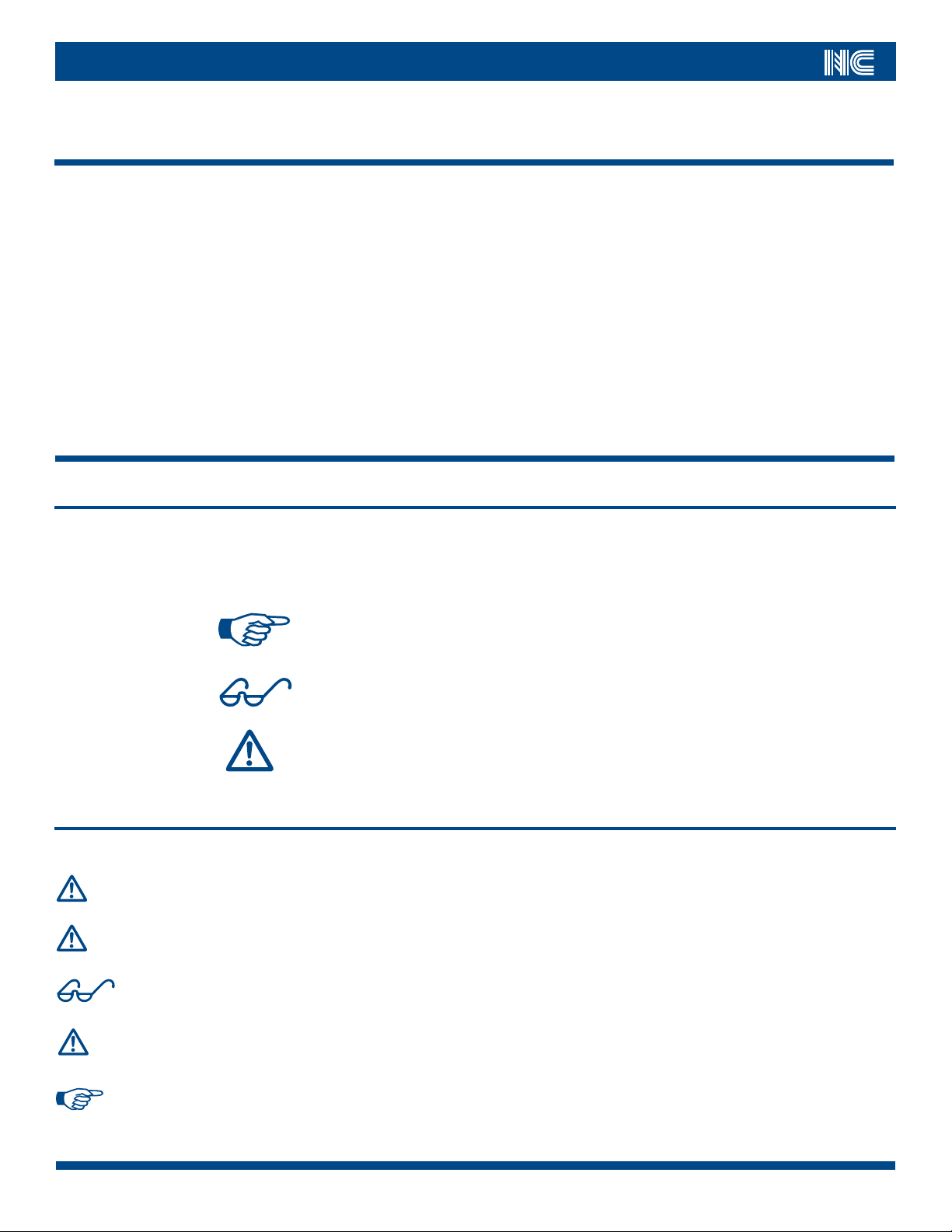
2.1 Symbols Used
Throughout this manual, information that is of particular importance to the installation, the safety of operating personnel and the protection of equipment are
highlighted by the following three symbols. The WARNING symbol is also used on the equipment wherever necessary.
NOTE: Calls attention to helpful tips about proper
installation, maintenance or use of the controller.
CAUTION: Highlights areas of concern that, if overlooked, could
result in damage to the controller or surrounding equipment.
WARNING : Alerts the installation, operating or maintenance
personnel of hazardous aspects of the controller, which, if
ignored could result in serious personal injury or death.
2.2 Precautions
When installing, using or servicing this product please adhere to the following precautions.
WARNING:
WARNING:
REPAIR & MAINTENANCE: Use only Nor-Cal replacement parts for product maintenance and repair,
and adhere strictly to rework instructions outlined in this manual.
PRODUCT ALTERATION: Do not alter or modify the product without first consulting with Nor-Cal
Products’ product management or applications engineering staff.
CAUTION:
WARNING:
NOTE:
Call toll free 800-824-4166 or 530-842-4457 • FAX 530-842-9130
MATERIAL COMPATIBILITY: Make sure to understand the compatibility between hazardous and
reactive process chemicals and the product’s materials of constructions.
OPERATION: The product’s moving parts present a severe pinching hazard. Please keep fingers,
hands or other objects away from all ports and openings.
INSTALLATION: Use proper installation hardware and mating components. In particular, make sure
that electrical connectors and pneumatic supply fittings are selected in accordance with the instructions
in this manual.
3
Page 4
N-Series Isolation Poppet Valves
3.0 - Specifications
The following figures and tables summarize specifications of the N-Series vacuum valve.
TABLE 3.1 ENVIRONMENTAL SPECIFICATIONS
FEATURE SPECIFICATION
Installation Orientation Product may be installed in any orientation, with gas flow in either direction.
Ambient Operating Temperature Range 32
Allowable Ambient Humidity 0
Process Temperature Range 0
Heating Capabilities Body can be heated up to 302o F (150o C) with optional heater kits.
Maximum internal Pressure 20 psi (138 kPa).
Maximum delta-P across poppet 30 psi (206 kPa) in open direction. 35 psi (241 kPa) in closing direction.
FEATURE SPECIFICATION
Open / Close speed 0.5 seconds to open, 0.7 seconds to close at 80 psig.
Pneumatic Supply 60
Solenoid Electrical Specifications 120 VAC: 2.5 Watt (-S11 option code)
Position Indicators Optical: Standard NPN type (-0 option code)
Reliability 3 million cycles MTBF at 90% confidence factor, clean environment
o
– 122oF (0oC – 50oC)
– 95% non-condensing
o
F – 392o F (-18o C – 200o C). Process temperatures above 302o F (150o C), may require use of seal materials other than
Viton®.
TABLE 3.2 OPERATIONAL SPECIFICATIONS
– 100 psig (414 – 689 kPa) CDA or N2.
Standard connection accepts 5/32” [4MM] OD tubing.
Thread is 10-32 [M5].
24 VDC: 1.8 Watt (-S21 option code)
240 VAC: 4.0 Watt (-S31 option code)
24 VAC: 4.0 Watt (-S41 option code)
Optical: Optional PNP type (-02 option code)
TABLE 3.3 CERTIFICATION
FEATURE SPECIFICATION
Leak Rate 1 x 10⁻⁹ atm.scc/sec He (for valves with Viton® seals)
44
Visit our Web Site www.n-c.com
Page 5
N-Series Isolation Poppet Valves
MODEL
NUMBER
NAP-075 0.75 No Flanges 1.42 (36) 3.95 (100) 4.90 (124) 1.6
NAP-075-NW 0.75 NW-16 1.57 (40) 4.10 (104) 5.05 (128) 1.7
NAP-075-CF 0.75 CF-133, Rotatable 1.91 (49) 4.73 (120) 5.68 (144) 1.9
NAP-100 1.0 No Flanges 1.82 (46) 4.35 (110) 5.30 (134) 1.6
NAP-100-NW 1.0 NW-25 1.97 (50) 4.50 (114) 5.45 (138) 1.7
NAP-100-CF 1.0 CF-212, Rotatable 2.28 (58) 4.81 (122) 5.76 (146) 1.9
NAP-150 1.5 No Flanges 2.41 (61) 4.94 (125) 5.89 (149) 1.6
NAP-150-NW 1.5 NW-40 2.56 (65) 5.09 (129) 6.04 (153) 1.7
NAP-150-CF 1.5 CF-275, Rotatable 2.62 (67) 5.15 (131) 6.09 (155) 1.9
NAP-200 1.5 No Flanges 2.61 (66) 5.14 (131) 6.09 (155) 1.6
NAP-200-NW 1.5 NW-50 2.76 (70) 5.29 (134) 6.24 (158) 1.7
NAP-200-CF 1.5 CF-338, Rotatable 2.84 (72) 5.37 (136) 6.32 (160) 1.9
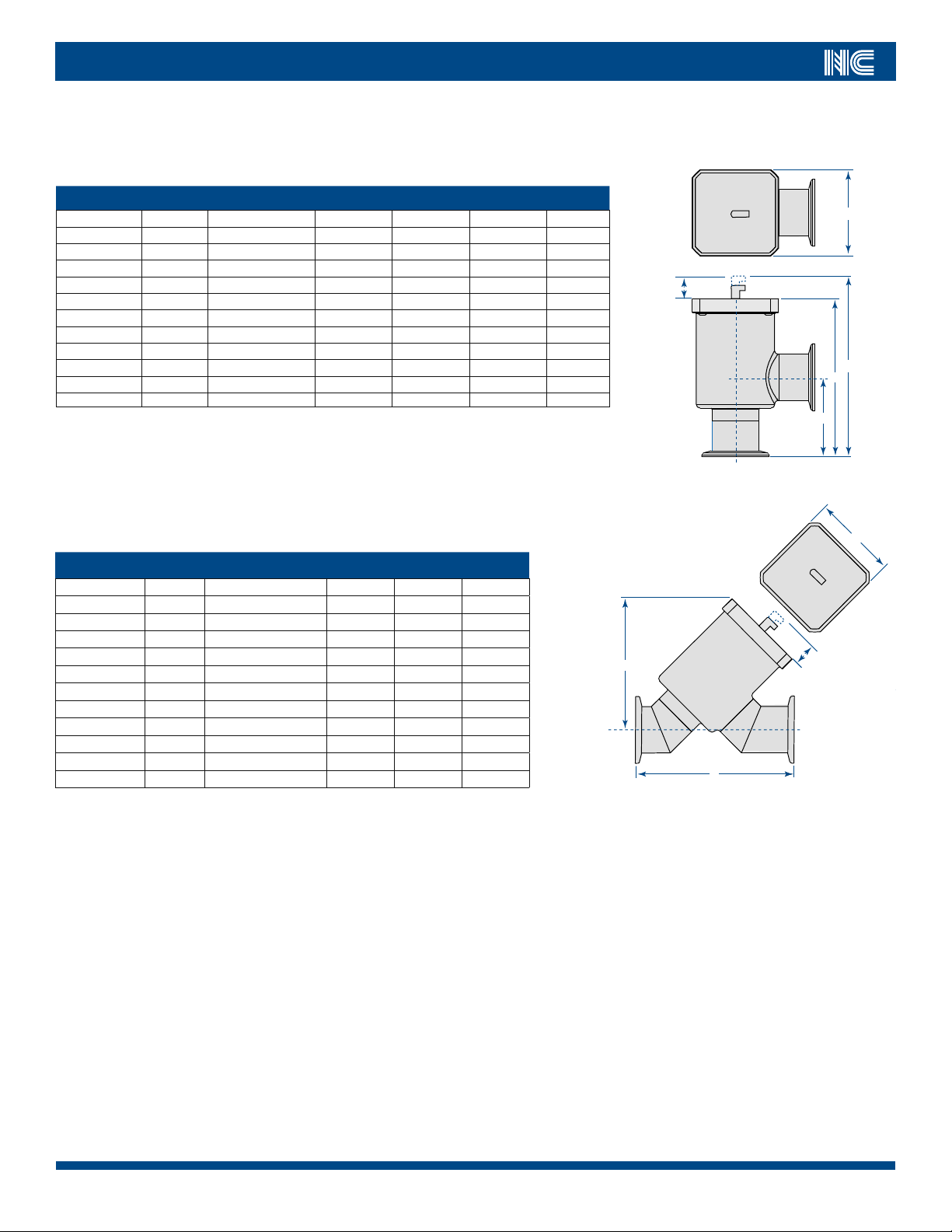
TABLE 3.4 PNEUMATIC N-SERIES ANGLE VALVE DIMENSIONS TABLE
PORT OD DESCRIPTIO N
A B C
TABLE 3.5 PNEUMATIC N-SERIES ANGLE IN-LINE VALVE DIMENSIONS TABLE
MODEL
NUMBER
PORT OD DESCRIPTI ON
A B
NAIP-075 0.75 No Flanges 3.64 (92) 4.60 (117) 1.7
NAIP-075-NW 0.75 NW-16 3.94 (100) 4.60 (117) 1.8
NAIP-075-CF 0.75 CF-133, Rotatable 4.20 (107) 4.60 (117) 2.0
NAIP-100 1.0 No Flanges 3.64 (92) 4.00 (102) 1.7
NAIP-100-NW 1.0 NW-25 3.94 (100) 4.00 (102) 1.8
NAIP-100-CF 1.0 CF-212, Rotatable 4.75 (121) 4.00 (102) 2.0
NAIP-150 1.5 No Flanges 4.82 (122) 4.37 (111) 1.7
NAIP-150-NW 1.5 NW-40 5.12 (130) 4.37 (111) 1.8
NAIP-150-CF 1.5 CF-275, Rotatable 5.24 (133) 4.37 (111) 2.0
NAIP-200 1.5 No Flanges 5.21 (132) 4.37 (111) 1.7
NAIP-200-NW 1.5 NW-50 5.51 (140) 4.37 (111) 1.8
NAIP-200-CF 1.5 CF-338, Rotatable 5.66 (144) 4.37 (111) 2.0
WEIGHT
(Lb.)
WEIGHT
(Lb.)
FIGURE 3.4.1
B
0.95 (24)
2.77 (70)
C
B
A
2.77 (70)
0.95 (24)
A
Call toll free 800-824-4166 or 530-842-4457 • FAX 530-842-9130
5
Page 6

N-Series Isolation Poppet Valves
4.0 Description of N-Series Valve
4.1 Overview
Nor-Cal Products N-Series valves are pneumatically operated bellows sealed poppet valves, designed for light weight and compact size as well as robust operation and long life. The pneumatic valve is controlled by a pneumatic cylinder located inside the top of the valve body for extra low profile and envelope size. The
valve closes by use of an internal spring. Supplying compressed air to the pneumatic cylinder opens the valve. In the event of a power or pneumatic failure the
valve closes automatically, and is therefore considered a “normally closed” or “fail close” design.
The electropolished 304 stainless steel valve body is available in a right angle or angle in-line configuration with a selection of flange types. Customer specific
flange arrangements and combinations are available upon request, as are a variety of O-ring seal types. Viton is the default elastomer material used.
Optional position indicators can be ordered with the valve, or they can easily be installed as a retrofit at the user’s site. The position indicators are mounted on a
small circuit board that resides in a molded slot in the valve top cover. No adjustment or bracket hardware is needed for the position indicator installation.
An air solenoid operated pneumatic valve may also be ordered with the valve. This valve allows electrical control of the N-Series valve while it is connected directly to the user’s pneumatic supply. The solenoid valves are available in 24 VDC as well as 24, 120 and 240 VAC varieties.
4.2 Theory of Operation
Figure 4.2.1 illustrates the components of the pneumatic N-Series valve. From its normally closed position, the valve is opened when compressed air is applied to
the pneumatic cylinder through the 10-32 [M5] female port (usually fitted with a 5.32” [4mm] quick disconnect fitting) in the valve stem). When the pneumatic
pressure in the cylinder reaches a level sufficient to overcome the force of the spring, the piston starts to rise, pulling the poppet off of the seat.
The actuator cylinder is vented to allow air from within the bellows to enter or escape as its volume changes. At the lower end of the stem, the poppet is permanently attached to the stem. The poppet includes an O-ring seal residing in a dovetail shaped O-ring groove, which contacts the seat to seal the valve port. The
bellows forms a flexible seal between the poppet and body valve housing.
As long as adequate pneumatic pressure is applied, the piston continues to travel upward, further compressing the spring, until the piston reaches the stop at the
full open position.
To close the valve, the cylinder is vented through the same 10-32 [M5] female port (usually fitted with a 5.32” [4mm] quick disconnect fitting). As the air pressure
falls below the value necessary to counter the spring force at the full open position, the piston and the poppet start to move towards the closed position. As venting continues, the poppet seat reaches the full close, sealed position.
66
Visit our Web Site www.n-c.com
Page 7

N-Series Isolation Poppet Valves
Air Cylinder
Bonnet Seal O-ring
Position Sensor Ring
Closing Springs
Piston
Side Port
Actuator Cap
Bottom Port
Activation Air Inlet
Standard with 360
Bellows
Valve Body
Poppet O-Ring
o
Swivel
Poppet
Position Sensor Board
(Optional)
Air Solenoid
(Optional)
Activation Air Inlet
Piston Seal
FIGURE 4.2.1
4.3 Valve & Options Nomenclature
FIGURE 4.3.1
N-Series Options
Please use the following part numbering
tree to add the appropriate options to a
standard N-Series valve model number.
Valve
Model Number
Example: NAP-150-NW-O- O-K79-S11-SS
Right angle N-Series valve with 1.5 inch bore, NW-40 flanges, redundant optical
position indicators, Kalrez 4079 O-rings, 120VAC air solenoid and soft start option.
Position
Indicator 1
Position
Indicator 2
O-ring
Type
Air
Solenoid
Soft
Start
5.0 Installation and Use
5.1 Unpacking and Detrashing
Unless otherwise requested, the N-Series valve is bagged and labeled according to standard clean room protocol. Outer packaging varies depending on the
number and types of valves ordered.
Before unpacking, please inspect the box thoroughly to make sure it is undamaged. Report any obvious signs of damage or tampering to the freight carrier.
Leave plastic bag intact until the product is ready to be transferred to a clean area.
NOTE: HARD COPY DOCUMENTATION: Printed operating manuals are no longer supplied in the packaging with Nor-Cal valve products. All
product documentation is available on-line at http://www.n-c.com/productdocumentation.aspx.
Call toll free 800-824-4166 or 530-842-4457 • FAX 530-842-9130
7
Page 8

N-Series Isolation Poppet Valves
5.2 Valve Installation
Every N-Series valve is packaged with plastic protective flange end-caps. Leave these caps in place until the product is ready to be installed in the piping manifold or vacuum system. Even the smallest scratch or nick on the flange sealing surface can significantly compromise the leak integrity of the vacuum system and
cause inadequate pump-down performance.
Be sure to always use the proper Nor-Cal flange connection hardware, including centering rings, O-rings, copper gaskets, clamps, nuts and bolts, etc.
CAUTION: BENDING MOMENTS: Improper installation of the N-Series valve may lead to failure of the valve to seal or permanent damage
to the valve housing body. Bending moments across the inlet and outlet flange connections should never exceed 50 ft-lb. Never
force two tube ends together with clamps or fastening hardware. Doing so will likely damage components in the line, such as a
valve. Instead, make use of flexible couplings to help join slightly misaligned sections of vacuum tubing.
5.3 Pneumatic Hook-Up
The standard N-Series valve comes equipped with a quick disconnect fitting. Use 5-32” [4mm] OD flexible tubing to supply compressed air to the valve.
Alternate tubing connections can be accommodated by replacing the quick disconnect fitting. The valve stem thread is 10-32 [M5].
5.4 Solenoid Valve Connection
Solenoid
Electrical Connection
Air Connection
(5/32”/4mm OD Tubing)
FIGURE 5.4.1
88
Visit our Web Site www.n-c.com
Page 9

N-Series Isolation Poppet Valves
5.5 Position indicator Electrical Connection
BLACK -Ground
GREEN - Closed
WHITE - Open
RED - +24 VDC
Input: +5 to +28 VDC
Output: NPN Standard
PNP Option available on request
FIGURE 5.5.1
6.0 Troubleshooting
Please refer to the following possible symptoms and root causes to troubleshoot your N-Series valve. Alternatively, you can contact Nor-Cal technical support at
800-824-4166. In many cases, the N-Series valve problem can be diagnosed and fixed in the field. Spare parts and kits can be found in Section 7 of this manual.
Should it be necessary to return a valve to Nor-Cal Products for service, then please refer to Section 8 for instructions.
CAUTION: FIELD SERVICE: Before attempting to diagnose or service a valve, please make sure that you have familiarized yourself with the
safe operation and maintenance of the valve (See Section 7). Compressed air and strong spring forces present potential hazards.
Make sure the valve is in a “safe state” before servicing by disconnecting the air supply line and /or the solenoid pilot valve power
supply.
CAUTION: FIELD SERVICE: While performing work on the N-Series valve, be certain to use only proper tools and any special fixtures or
assembly aids recommended or supplied by Nor-Cal Products.
6.1 Valve Will Not Close and Remains Fully or Partially Open
Observe the pneumatic connection on top of the valve to watch the valve stem rise and fall. A completely closed valve should show the valve stem / push-to-fitconnector interface flush with the top cap of the valve. If the valve does not appear to be closing completely, possible causes include:
• An obstruction inside the valve that prevents the poppet from seating all the way (ex. process debris).
• A broken or worn spring in the valve actuator.
• Degraded or inadequate lubrication in the pneumatic cylinder.
• A complete or partial blockage of the air vent from the pneumatic cylinder
• A faulty solenoid valve, whereby it does not cut off pneumatic supply to the valve or allow the pneumatic cylinder to vent.
Call toll free 800-824-4166 or 530-842-4457 • FAX 530-842-9130
9
Page 10

N-Series Isolation Poppet Valves
6.2 Valve Will Not Open All The Way or At All
Observe the pneumatic connection on top of the valve to watch the valve stem rise and fall. A completely open valve should show the valve stem / push-to-fitconnector interface about 0.4” (10mm) above the top cap of the valve. If the valve does not appear to be opening completely, possible causes include:
• Inadequate air supply pressure. (Minimum pressure is 60 psig [414 kPa])
• A kink or blockage in the pneumatic supply line or inlet fitting.
• A faulty solenoid valve, whereby the pressurized air is not routed to the pneumatic cylinder
• Pneumatic air cylinder piston O-ring leak. (Listen for hissing and feel for air escaping between the stem and the top cap near the air inlet fitting.)
• Piston stem seal leak causing compressed air to enter inside of bellows. (Listen for hissing and feel for air escaping between the stem and the top cap
near the air inlet fitting.) This failure mode can also lead to overpressure and failure of the bellows, in which case compressed air would enter the
vacuum system.
6.3 Valve Does Not Seal Adequately As Measured Between Inlet and Outlet Ports
This failure is most often related to the poppet O-ring seal. Consider the following possibilities:
• Poppet seal O-ring is defective, such as being cracked, chipped, process hardened, etc.
• Poppet seal O-ring is contaminated with process debris.
• Poppet valve seat is contaminated with process debris.
• Valve is not closing fully (refer to Section 6.1)
6.4 Vacuum System Will Not Pump Down To Base Pressure
This usually indicates a leak in the vacuum system or a problem with the vacuum pump. There are naturally many different possible causes for this problem, and
some may have nothing to do with the N-Series valve at all. A basic pump operation and vacuum line integrity check should be performed first to narrow the
problem down. If, by process of elimination, it is suspected that a system leak is stemming from the N-Series valve please check the following:
• If available, use a He-leak detector to determine the exact location of the leak. Verify leak integrity at the inlet and outlet flanges as well as in and
around the top cap of the valve.
• Flange leaks can occur if the flanges or O-rings were damaged during installation.
• A valve body leak could occur if the valve was subjected to severe bending moments during installation. Look for signs of deformed port protrusions
and subsequent cracking.
• If the static top cap O-ring is compromised, then ambient air will leak in to the valve body cavity and on in to the vacuum system.
• If the valve bellows is cracked or broken, then ambient air will leak in to the vacuum system through the annulus between the stem and the top cap
near the air inlet fitting.
Seal and bellows kits are available to repair a defective valve in the field. Please refer to Section 7 for spare parts ordering details.
6.5 Position Indicators Are Not Sending Open / Close Signals
The position indicators are designed to provide remote indication when the N-Series valve is either fully open or fully closed. There is a reflective ring on the valve
stem that is used to trigger the optical detection circuit used in the position sensing. If open / close signals are not received by the customer, please consider
these causes:
• The valve is not closing fully, thereby not triggering the closed indicator. (see Section 6.1)
• The valve is not opening fully, thereby not triggering the open indicator. (see Section 6.2)
• The sensor cable is not connected properly or the connector pin-out is wrong. (Refer to Section 5.5 for proper position indicator connection.)
• The position indicator is broken and needs replacement.
The N-Series valve position indicators are mounted on a printed circuit board which, in turn, is located in a preformed slot in the valve actuator cap. It is held in
place by the label on top of the valve. This label must be removed in order to access the position indicator circuit board.
1010
Visit our Web Site www.n-c.com
Page 11

N-Series Isolation Poppet Valves
6.6 Valve Makes Noise
Under normal circumstances, the N-Series valve will make a very faint sound when actuated. This sound stems from the spring compressing and coming in intentional contact with the guides inside the pneumatic cylinder housing. If the valve starts making loud scraping or vibrational noises, then a more serious problem
has developed. Please contact Nor-Cal technical support at 1-800-824-4166.
6.7 Air Supply Solenoid Valve Is Leaking or Makes Noise
The air solenoid valve is controlled by a small electromagnetic solenoid coil, which typically lasts for millions of cycles. When operating normally, this part will
not make any sounds other than a light clicking when opened or closed. If compressed air starts to leak through the valve, or if it makes a buzzing sound, it is
possible that the valve is about to fail and replacement is necessary. A leading cause of premature failure is improper voltage. Check the power supplied to the
solenoid valve and make sure it meets the specifications.
7.0 Spare Parts & Accessories
This section contains ordering information as well as service and installation instructions for O-ring seal kits, replacement bellows and actuator assemblies, in
addition to solenoid valve and position indicator upgrade or replacement options.
CAUTION: FIELD SERVICE: Before attempting to diagnose or service a valve, please make sure that you have familiarized yourself with the
safe operation and maintenance of the valve (See Section 7). Compressed air and strong spring forces present potential hazards.
Make sure the valve is in a “safe state” before servicing by disconnecting the air supply line and /or the solenoid valve power
supply.
CAUTION: FIELD SERVICE: While performing work on the N-Series valve, be certain to use only proper tools and any special fixtures or
assembly aids recommended or supplied by Nor-Cal Products.
7.1 O-Ring Seal Kits
The N-Series valve contains two serviceable O-rings which include the main poppet seal and the bonnet seal (see Figure 4.2.1). N-Series valves sized from .75” to
2” use the same set of seals. The standard O-ring compound is Viton. Other compounds are available. [Aflas
etc…].
NOTE: ORDERING REPLACEMENT SEALS: Please make sure to have the part number or serial number of the valve available when ordering seal
replacements in the event you are not sure which seal compounds were originally installed.
Common replacement seal kits include:
®
NA-075-95: Viton
NA-075-95-K79: Kalrez
NA-075-95-C13: Chemraz
NOTE: Other seal materials are available. Call for details.
To replace the O-ring seals, please see the following instructions :
poppet and bonnet replacement O-rings
®
4079 poppet and bonnet replacement O-rings
®
513 poppet and bonnet replacement O-rings
®, Buna-N®, Chemraz®, Dupra®, Kalrez®, Perlast®,
Call toll free 800-824-4166 or 530-842-4457 • FAX 530-842-9130
11
Page 12

N-Series Isolation Poppet Valves
7.1 Replacing O-Ring Seal
1
Remove air fitting, if installed.
Install vented screw with large
flat washer [supplied in kit] until
screw stops.
Do NOT overtighten.
(This partially opens the valve
allowing the bellows /actuator
assembly to be removed.)
3
Grasp actuator top and lift
bellows /actuator assembly out
of body.
2
Remove the four button head
screws securing the bellows /
actuator assembly to the body
using a 3/32” hex key.
4
Remove and discard the old
bonnet and poppet O-rings.
Avoid scratching the seal
surfaces by using a plastic O-ring
pick to remove the O-rings.
5
Using an IPA soaked cleanroom
wipe thoroughly clean the
bonnet and poppet O-ring
grooves as shown.
7
Carefully install the sub assembly
into the body. Be sure that the
body O-ring is seated into the
groove.
6
Wipe O-rings with IPA and blow
dry with CDA. Evenly apply a
light sheen of Krytox to both
O-rings.
Install the O-rings. Wipe off any
excess Krytox with an IPA soaked
cleanroom wipe.
8
Place a small amount of anti-seize
onto the button head screws.
Insert the button head screws.
When all four screws are in place
tighten down and torque to 15 in.
lbs. using a cross pattern.
Now that the screws are torqued
in place it is safe to remove the
vented screw and flat washer
from the top cap. Thread the air
fitting into the stem to complete
the valve.
1212
Visit our Web Site www.n-c.com
Page 13

N-Series Isolation Poppet Valves
7.2 Valve Rebuild Kit
All N-Series valves port size 0.75” thru 2”, use the actuator rebuild kit. The rebuild kit consists of the pneumatic / spring actuator and the bellows assembly. The
rebuild kit does NOT include the poppet and bonnet O-rings, solenoid valves or position indicators. These parts should either be reused from the original parts,
or they need to be ordered separately (refer to Sections 7.1, 7.3 and 7.4 as applicable).
The valve rebuild kit can be ordered under part number:
NA-075-99: Rebuild kit fits sizes 0.75” – 2” N-Series valves.
To rebuild the N-Series valve, please follow the same instructions as outlined in section 7.1 for replacing the O-ring seal.
7.3 Replacement or Add-On Solenoid Valve Kit
The N-Series valve can be equipped with four different solenoid (air pilot) valves, including operating voltages of 24 VDC, 120 VAC, 240 VAC and 24 VAC.
NOTE: ORDERING SOLENOID VALVES: Please make sure to have the part number or serial number of the valve available when ordering the
solenoid valve replacements in the event you are not sure which solenoid type (operating voltage) was originally installed.
The solenoid replacement kits include:
N-S11-K: 120 VAC solenoid kit
N-S21-K: 24 VDC solenoid kit
N-S31-K: 240 VAC solenoid kit
N-S41-K: 24 VAC solenoid kit
To add or replace the N-Series solenoid valve, please see the following instructions :
1
Air Fittings
Install the two air fittings
and air filter onto the
solenoid as shown.
The straight air fitting
accepts a 5/64“ or 2mm
hex key internally for easy
fastening.
Filter
3
Attach the solenoid
assembly to the bracket
using the two 4-40 x
1/2” screws supplied.
2
Install solenoid bracket
using the two 4-40 x
1/4” thread forming
screws supplied.
4
Insert the poly tubing
into the air fitting of the
valve and the air fitting
of the solenoid.
Call toll free 800-824-4166 or 530-842-4457 • FAX 530-842-9130
13
Page 14

N-Series Isolation Poppet Valves
5
Solenoid test:
Insert air supply line into the straight fitting on the solenoid.
Apply 60 to 100 psi air pressure.
Valve should not open until power is applied. Verify valve opens with power is applied and closes when
power is removed.
Alternately you can actuate the solenoid valve by pressing the manual actuation button.
Actuation
Button
7.4 Replacement or Add-On Position Indicator
The N-Series valve position indicators are mounted on a printed circuit board which, in turn, is located in a preformed slot in the top housing of the valve. It is
held in place by the label on top of the valve. This label must be removed in order to access the position indicator circuit board. As such, the position indicator
replacement or add-on kit includes a spare label to be used, since the original adhesive likely will not be adequate to be used a second time.
The position indicator kit can be ordered under part number N-O-K.
Position indicator kit includes the circuit board, connection cable and top label.
To add or replace the N-Series position indicator,
please see the following instructions :
1
Remove the air fitting if installed.
Remove the label to access the
position indicator card slot.
Replacement label is included in
the kit.
Install the sensor board with the
optics toward the stem, and the
electrical connector located at the
top of the valve facing away from
the stem.
Do Not wear latex gloves when
handling boards!!!
3
Connect position indicator cable
as shown.
Connect air line for normal valve
operation.
BLACK -Ground
GREEN - Closed
WHITE - Open
RED - +24 VDC
Input: +5 to +28 VDC
Output: NPN Standard
PNP Option available on request
2
Place label onto valve as shown
so the electrical connector is
accessible through the opening
in the label.
Reinstall the air fitting.
4
When the valve is in the open
position the “I” led should illuminate on the valve as shown.
When the valve is in the closed
position the “0” led should illuminate on the valve as shown
1414
Visit our Web Site www.n-c.com
Page 15

N-Series Isolation Poppet Valves
8.0 Product Support & Returns
Many product support documents are available for viewing and download on the Nor-Cal Products website (www.n-c.com). Look for Frequently Asked
Questions, Product Support, Operating and Service Manuals, 3D CAD models, and more. If you prefer, you may also reach Nor-Cal’s Sales and Technical Support
departments by phone at 800-824-4166.
To inquire about and schedule a product return, you may contact our RMA Coordinator directly by e-mail at RMA@n-c.com.
NOTE: RETURNING PRODUCT TO NOR-CAL: Do NOT return any parts to Nor-Cal Products without first being issued an RMA number. Any
such shipments will be returned to you immediately.
This process may also be completed on-line by accessing the necessary forms in the RMA section of the Nor-Cal website (http://www.n-c.
com/rma.aspx).
We are very concerned that we do not inadvertently expose our employees to hazardous materials as a result of handling components that
have been returned for rework or repair. In compliance with Federal OSHA Safety Standard 1910-1200, Hazard Communications “Right to
Know”, Nor-Cal Products requires that a signed RMA (Return Material Authorization) form be completed to preclude any potential health
risk or exposure to our employees that may occur during receiving, evaluating, disassembling/ assembling, cleaning, machining, welding or
handling potentially contaminated products. The RMA (Return Material Authorization) may be returned by fax, e-mail or mail prior to issuance
of an RMA (Returned Material Authorization) number.
If the products have been used, complete the PCDS (Product Contamination Data Sheet) section of the RMA form. Please provide specific
information regarding the type of process in which the parts were used, the process chemicals they were exposed to, and the residues that may
remain on the parts. Nor-Cal Products, Inc. is particularly concerned with compounds that outgas at room temperature and pressure. Strong
odors emanating from a part may significantly delay or even stop work on a returned part.
NOTE: The PCDS section of the form must be filled out completely, and signed by a person authorized to do so by the Customer.
After the PCDS has been reviewed and accepted by Nor-Cal Products, the RMA number will be issued and shipping instructions will be
forwarded to you.
Please use the following step-by-step guideline in completing this procedure:
1.
Fill out the RMA and fax or mail it to Nor-Cal Products. Use the fax number or mailing address on the header of the RMA form.
2.
Clean the part to meet DOT shipping and OSHA handling practices. If this cannot be done, contact Nor Cal Customer Service to determine a course of
action. Nor-Cal will not accept any contaminated product without written evidence of decontamination.
3.
Seal the part in a plastic bag.
4.
Package and ship the bagged part to Nor-Cal Products according to the RMA instructions.
5.
Clearly write the RMA# on the outside of the box and, if possible, also write it on the bag or attach a copy of the RMA to the bagged part.
NOTE: The RMA number must be clearly visible on the outside of the package, or included on the shipping label and the packing
slip. It is also recommended that the RMA number or a copy of the RMA be attached to the bagged part inside the package.
Packages received without an RMA number clearly visible, will promptly be returned to the sender.
Nor-Cal Products, Inc. reserves the right to refuse delivery of parts for improper or inadequate cleaning, incomplete or
inadequate PCDS or RMA information, or for any other reason that may bring into question the safety of Nor-Cal employees.
Recommended Cleaning Facilities: For additional questions:
TMPI Phone: 530-841-9184
Phone: 510-786-0680 FAX: 866-640-9012
Chemetal E-mail:
rma@n-c.com
Phone: 510-783-5050
Call toll free 800-824-4166 or 530-842-4457 • FAX 530-842-9130
15
Page 16

N-Series Isolation Poppet Valves
RMA #
www.n-c.com
1967 South Oregon Street, Yreka, California 96097
800-824-4166
•
530-842-4457 • FAX: 530-842-9130
Return Material Authorization
It is mandatory to obtain an RMA from Nor-Cal Products before returning any parts, items or materials. Complete the requested information in the Sections
below and fax this form to Nor-Cal Products, attention RMA Coordinator at fax# 866- 640-9012 or 530-842-9130.
Section A Customer Contact Information
Company Name
Contact Name
Telephone e-mail address
Original P.O.# Sales Order #
Section B Item to be returned
*NOTE: If part is NEW (never been used) and still in the original Nor-Cal packaging, check the box in the New column, skip Section C PCDS, and sign and date
Section D. If part has been removed from the original packaging, do NOT check the NEW box; continue to Sections C and D.
Part Number Serial Number Quantity New? PCDS
Reason for Return
Do you need a replacement for this part? (Include replacement P/N, if known)
Section C Product Contamination Data Sheet
Type of process
Chemical exposure history
Cleaning performed
Describe any expected residues on returned part
*NOTE: IF TWO PARTS WITH OR WITHOUT THE SAME MODEL NUMBER HAVE BEEN EXPOSED TO DIFFERENT CHEMIC ALS THEY MUST BE LISTED ON SEPARATE
SHEETS. MAKE DUPLICATE COPIES OF THIS FORM AS NEEDED.
Section D Legally Binding Declaration
I represent that the information in this declaration is correct and complete to the best of my knowledge. I, the undersigned, have sufficient knowledge
regarding the condition of the product to complete this form. I am aware of the potential liabilities for damages and undertake to be responsible for such
damages to the extent that the damages are caused by incomplete or inaccurate information on this form. I certif y that I have provided accurate information
to Nor-Cal Products or its Representatives and understand that any discrepancy between the information that I have provided and the part returned under
the RMA may cause the RMA to be revoked and the part returned to me at my expense.
Signature Date
Section E TO BE COMPLETED BY NOR-CAL PRODUCTS
Your RMA is: Your shipment is authorized Shipper &
_ _______ ____ _______ ____ ___ ____ ____ ___ _ for freight collect (Y/N) ___ ____ ___ __ account: _____ ____ ___ ____ ____ ___ ____ ____ ___ _
Date reviewed
Determination
RMA # assigned
Welding Allowed? Yes
Cleaning Allowed? IPA
Signature MSDS Review
Signature
Please return goods to: Nor-Cal Products Inc., 1967 South Oregon Street, Yreka, CA 96097
Repair Technician
Rework/Repair Instructions
o
No o Eval.
o H2O Descale Chem Clean EP
Repair Date
I have reviewed the PCDS and corresponting MSDS’s.
AND
I understand how to safely handle these parts that may contain the
following contaminants
o
Signature
Date
1616
Visit our Web Site www.n-c.com
Page 17

N-Series Isolation Poppet Valves
Appendix
Limited Warranty
Products manufactured by Nor-Cal Products, Inc. (hereinafter referred to as “Nor-Cal”) are warranted against defects in material and workmanship for a
period of twelve (12) months from the date of shipment from Nor-Cal to the buyer. Any modification to the product by the buyer or their agent voids this warranty. Liability under this warranty is expressly, limited to replacement or repair (at Nor-Cal’s option) of defective parts. Nor-Cal may at any time discharge its
warranty as to any of it products by refunding the purchase price and taking back the products. This warranty applies only to parts manufactured, and labor
provided, by Nor-Cal under valid warranty claims received by Nor-Cal within the applicable warranty period and shall be subject to the terms and conditions
hereof. Expendable items such as tubes, heaters, sources, bellows, etc., by their nature may not function for one year; if such items fail to give reasonable service
for a reasonable period of time, as determined solely by Nor-Cal, they will be repaired or replaced by Nor-Cal at its election. All warranty replacement or repair
of parts shall be limited to equipment malfunctions which, in the sole opinion of Nor-Cal,are due or traceable to defects in original materials or workmanship.
Malfunctions caused by abuse or neglect of the equipment are expressly not covered by this warranty. Nor-Cal expressly disclaims responsibility for any loss or
damage caused by the use of its products other than in accordance with proper operating and safety procedures. Reasonable care must be taken by the user to
avoid hazards. In-warranty repaired or replacement parts are warranted only for the remaining unexpired portion of the original warranty period applicable to
the parts that have been repaired or replaced. After expiration of the applicable warranty period, the buyer shall be charged at Nor-Cal’s then current prices for
parts and labor plus transportation. Except as stated herein, Nor-Cal makes no warranty, expressed or implied (either in fact or by operation of law), statutory or
otherwise: and, except as stated herein, Nor-Cal shall have no liability for special or consequential damages of any kind or from any cause arising out of the sale,
installation, or use of any of its products. Statements made by any person, including representatives of Nor-Cal, which are inconsistent or in conflict with the
terms of this warranty shall not be binding upon Nor-Cal unless reduced to writing and approved by an officer of Nor-Cal. Merchandise may be returned at the
sole discretion of Nor-Cal Products, but not more than 60 days after shipment. A fee may be charged for restocking the item. An RMA number must be obtained
from Nor-Cal before returning any merchandise.
Intellectual Property
The products described in this manual are covered under U.S. Patents.
1717
Visit our Web Site www.n-c.com
 Loading...