

Page 1
APC-OP Manual Addendum –
Tel: 800-824-4166
or 530-842-4457
Fax: 530-842-9130
www.n-c.com
1967 So. Oregon
Yreka, CA 96097 USA
Nor-Cal Products, Inc.
Section 10
LCD Front Panel Interface
8-2010
Page 2
10.0 Front Panel Interface Operation
Controller models with a part number in the form APC-x50-A have a touch screen LCD front panel interface, in addition to a Serial and Analog/TTL port. On
these models, the functionality of the Serial and Analog/TTL interfaces is identical to that previously described in sections 6.0 and 7.0 of the APC-OP Manual. This
section is dedicated to describing the use and operation of the front panel touch screen.
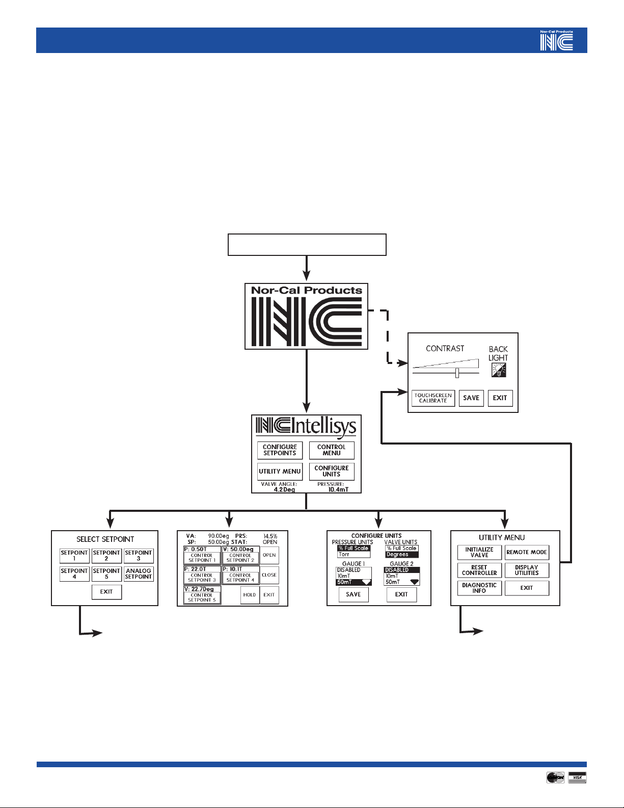
The front panel touch screen interface has been designed with ease of use in mind. Every function is accessible with only a few keystrokes, and most pages are
menu based. A top-level schematic of the interface is shown in Figure 10.1 below.
POWER ON - START
more...
Figure 10.1 – Top Level Front Panel Screen Menu Tree
2
2
Visit our Web Site www.n-c.com
more...
Page 3
10.1 Commonly Used Function Buttons
Navigating through the various menus of the front panel LCD interface, the user will find that some functions and associated buttons are used in more than one
place. This includes the SAVE, SET VALUE, BACK SPACE, CLEAR, BACK and EXIT functions.
The SAVE function is generally found on set-up type screens. This button must be pressed before exiting to another page allowing the set-up information to be
stored in NVRAM. Exiting without pressing SAVE will result in the old information being used.
The SET VALUE function is used on pages where numerical information is entered. Similar to the SAVE function, the SET VALUE button has to be pressed in
order for the new number to be stored in NVRAM.
The BACK SPACE button is also found on pages where numerical information is entered. Pressing the BACK SPACE button simply erases the last digit entered.
For example, if the numbers 1 2 3 were entered and then the BACK SPACE button was pressed, then the numbers 1 2 remain on the command line.
On a parallel path, the CLEAR function will erase the entire numerical entry on the screen. So, if the numbers 1 2 3 were entered followed by the CLEAR button
being pressed, then no numbers would be left on the command line.
The BACK button is used to go back to the previous screen.
The EXIT button is used to go all the way back to the MAIN MENU screen.
10.2 Basic Operation
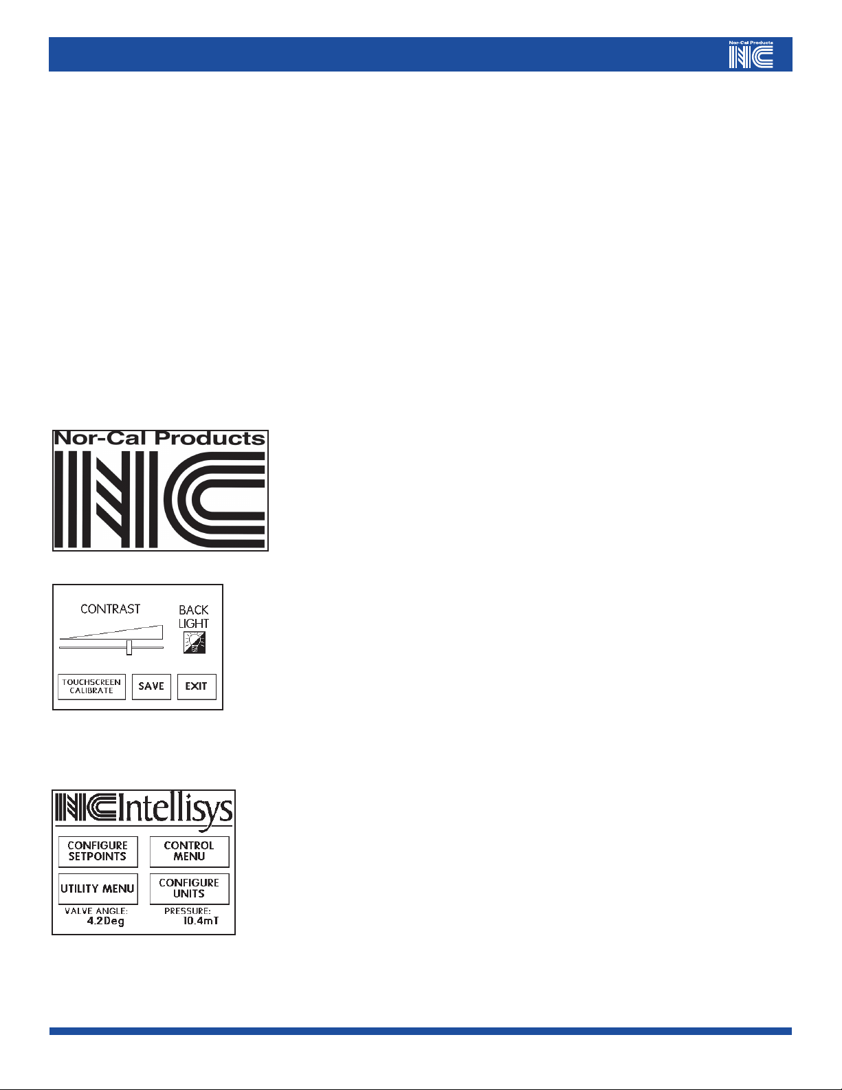
Once the APC is first powered on the NOR-CAL LOGO page will come on for approximately three seconds. At
the same time, the valve initialization routine will commence if the controller is connected to a butterfly valve.
Controllers that are connected to a gate- or pendulum valve will remain in a “safe mode” which effectively
delays the valve initialization until the operator gives a “clear to proceed” command. If the NOR-CAL LOGO
screen is touched during the first three seconds, an LCD SET-UP page will appear.
The LCD SET-UP page allows the user to:
a) change the screen contrast by sliding the CONTRAST bar left or right. Be careful not to set too little or too
much contrast, as screen legibility may be compromised to the point where no information can be seen.
b) turn on or off the BACK LIGHT. Operating the screen with the BACKLIGHT off may extend its useful life.
c) perform an LCD screen X-Y calibration, as needed. This function essentially correlates the position of graphics
information to physical position on the touch screen matrix. A calibration is done on each front panel display by
Nor-Cal Products before shipment, and recalibration by the customer may seldom or never be required.
Once all LCD screen settings are adjusted appropriately, press SAVE to store the information in memory followed by EXIT to return to the MAIN MENU page.
The MAIN MENU page simply serves as a central node used in navigation to the various sub menu pages.
From this screen, the user can access sub-menus that are used:
a) to configure set-point parameters such as value, type and certain tuning parameters
b) to perform utility functions such as valve initialization, controller reset and LCD set-up
c) to configure engineering units for pressure and valve position, and
d) in the active control mode of the controller and valve system
The MAIN MENU also displays real time values for both pressure and valve position, and is therefore
intended to be the page that is displayed whenever the controller is in normal operation mode.
Call toll free 800-824-4166 or 530-842-4457 • FAX 530-842-9130
3
Page 4

10.3 CONFIGURE SETPOINTS
CONFIGURE SETPOINTS is the first sub-menu directly accessible from the MAIN MENU screen. Figure 10.2 shows a navigation tree detailing this part of the
function software.
MAIN
MENU
More similar ones for SET
Figure 10.2 – CON FIGURE SETPOINTS Navigation Tree
The SELECT SETPOINT page allows the user to choose which set-point is to have
its parameters manipulated. All parameters of setpoints 1 to 5 can be set from this
screen. However, only the “tuning parameters” such as GAIN, PHASE and KAP can
be set for the ANALOG SETPOINT. The latter’s value and type are determined by
what input is provided on the Analog/TTL port.
4
4
GAIN, SET PHASE and SET
Visit our Web Site www.n-c.com
Page 5

The SELECT ATTRIBUTE page for each setpoint allows the user to pick which attribute(s) to program. Pressing
SETPOINT will bring up a number pad screen via which a numerical value can be given to the setpoint.
Pressing the SP TYPE button repeatedly causes the setpoint type to toggle between “valve” and “pressure” – in
other words choosing a “valve” type here means that the setpoint, when activated, will drive the valve to a prescribed
position as opposed to controlling to a particular pressure.
SET GAIN, SET PHASE and SET KAP are also functions that will bring up a number pad by which the value can be
changed. However, the user is advised that these parameters do not normally need to be adjusted beyond the factory settings, because the controller contains an advanced adaptive pressure control algorithm that will work well
under most conditions.
In all cases are the current values for SETPOINT, etc. displayed above each button. Pressing BACK or EXIT from the
SELECT ATTRIBUTE page automatically stores the SP TYPE entry in NVRAM.
The number pad, in this case shown for the “setpoint 1” value entry provides the necessary interface to key in the
desired numerical entry. Be sure to pay attention to the MIN and MAX values, as these limits provide the lower and
upper range for the value in question. Pressing SET VALUE at the end saves the information to NVRAM. Pressing
EXIT without pressing SET VALUE will return the user to the MAIN MENU without saving the entered information.
Call toll free 800-824-4166 or 530-842-4457 • FAX 530-842-9130
5
Page 6

10.4 UTILITY MENU
The UTILITY MENU is another sub-menu directly accessible from the MAIN MENU screen. Figure 10.3 shows a navigation tree detailing this part of the function
software.
MAIN
MENU
more...
Figure 10.3 – UTILITY MENU Navigation Tree
6
6
Visit our Web Site www.n-c.com
Page 7

The UTILITY MENU page simply serves as the means to reach the five functions contained under this category,
including INITIALIZE VALVE, RESET CONTROLLER, DIAGNOSTIC INFORMATION, REMOTE MODE and
DISPLAY UTILITIES.
Pressing the INITIALIZE VALVE button on the UTILITY MENU page brings up the CONFIRM VALVE
INITIALIZATION dialogue screen. By pressing YES here, the controller will initialize the valve, which means all
other functions will cease to respond until initialization is complete. This is one of the ways a gate- or pendulum
valve controller can be given the “clear to proceed” command after first being powered up. The first time that
the controller initializes a gate- or pendulum valve, it will go through a full extensive routine lasting for about one
minute. All subsequent times, a shorter initialization routine will be used. If a gate- or pendulum valve controller is used to control a different valve than it was first used to initialize, it is imperative that the controller be reset
(see below) before initializing and operating. For butterfly valve controllers, the same initialization routine will
be used at all times. Pressing NO on the CONFIRM VALVE INITIALIZATION screen will return the user to the
UTILITY MENU page.
Pressing the RESET CONTROLLER button on the UTILITY MENU will bring up the CONFIRM CONTROLLER
RESET dialogue screen. By pressing YES here, the controller will momentarily turn off power to the processor
and clear all motor initialization data stored in NVRAM (other data in NVRAM such as set-point information will
be retained). Once the processor comes back on line, the controller will initialize the valve if it is a butterfly type.
If the valve is a gate- or pendulum type, the controller will stay in “safe mode” awaiting a “clear to proceed”
command from the operator. Pressing NO on the CONFIRM CONTROLLER RESET screen will return the user to
the UTILITY MENU page.
Pressing the DIAGNOSTIC INFO button on the UTILITY MENU makes certain controller information available.
This screen will list firmware revision levels as well as the serial number of the finished product as it was produced
by Nor-Cal Products. This information can be useful in diagnosing problems if/when they occur. EXIT will return
the user to the MAIN MENU page.
The REMOTE MODE button on the UTILITY MENU page currently only serves as a display screen for valve,
pressure and setpoint information. It does NOT provide any lock-out or other safety features. With or without
the REMOTE MODE screen displayed, the controller can be commanded via any of its three user interfaces using
“whoever talks last” priority. Pressing EXIT will return the user to the MAIN MENU page.
Pushing DISPLAY UTILITIES on the UTILITY MENU brings up the LCD SET-UP page. Please refer back to
Section 10.2 for details about the functionality of this page.
Call toll free 800-824-4166 or 530-842-4457 • FAX 530-842-9130
7
Page 8

10.5 CONFIGURE DISPLAY UNITS
The ability to CONFIGURE DISPLAY UNITS is directly accessible form the MAIN MENU. This screen allows the
user to change engineering units for both pressure and valve position. Also, this page is used to set the full scale
range of each gauge used. Please make sure to press the SAVE button prior to exiting back to the MAIN MENU.
The CONTROL MENU page, also directly accessible from the MAIN MENU, is the primary screen intended for
manual operation. From this page, the push of a single button will cause the controller-and-valve system to act
on either one of five preprogrammed (by the user) setpoints or on one of three discrete valve commands, including OPEN, CLOSE and HOLD. Current values for valve position as well as pressure are displayed at the top of the
CONTROL MENU page. The value and type of each preprogrammed setpoint is also included at the top of each
button. To change the value or type of setpoint, please refer to the CONFIGURE SETPOINTS instructions in
Section 10.3. Pressing EXIT from the CONTROL MENU page will leave the controller-and-valve system control-
ling to the last instruction issued, but will return the display back to the MAIN MENU.
NOTE: The front panel interface function is a new feature on Nor-Cal Products’ controllers effective December 2003. More functions will
be added over a period of several months. Please do not hesitate to contact Intellisys Product Management at (800) 824-4166, or e-mail to
ncsales@n-c.com for questions or suggestions about this product.
8
8
Visit our Web Site www.n-c.com
Page 9

Appendix II - Limited Warranty and Intellectual Property Coverage
Products manufactured by Nor-Cal Products, Inc. (hereinafter referred to as “Nor-Cal”) are warranted against defects in material and workmanship for a
period of twelve (12) months from the date of shipment from Nor-Cal to the buyer. Any modification to the product by the buyer or their agent voids this warranty. Liability under this warranty is expressly, limited to replacement or repair (at Nor-Cal ’s option) of defective parts. Nor-Cal may at any time discharge its
warranty as to any of it products by refunding the purchase price and taking back the products. This warranty applies only to parts manufactured, and labor
provided, by Nor-Cal under valid warranty claims received by Nor-Cal within the applicable warranty period and shall be subject to the terms and conditions
hereof. Expendable items such as tubes, heaters, sources, bellows, etc., by their nature may not function for one year; if such items fail to give reasonable service
for a reasonable period of time, as determined solely by Nor-Cal, they will be repaired or replaced by Nor-Cal at its election. All warranty replacement or repair
of parts shall be limited to equipment malfunctions which, in the sole opinion of Nor-Cal,are due or traceable to defects in original materials or workmanship.
Malfunctions caused by abuse or neglect of the equipment are expressly not covered by this warranty. Nor-Cal expressly disclaims responsibility for any loss or
damage caused by the use of its products other than in accordance with proper operating and safety procedures. Reasonable care must be taken by the user to
avoid hazards. In-warranty repaired or replacement parts are warranted only for the remaining unexpired portion of the original warranty period applicable to
the parts that have been repaired or replaced. After expiration of the applicable warranty period, the buyer shall be charged at Nor-Cal’s then current prices for
parts and labor plus transportation. Except as stated herein, Nor-Cal makes no warranty, expressed or implied (either in fact or by operation of law), statutory or
otherwise: and, except as stated herein, Nor-Cal shall have no liability for special or consequential damages of any kind or from any cause arising out of the sale,
installation, or use of any of its products. Statements made by any person, including representatives of Nor-Cal, which are inconsistent or in conflict with the
terms of this warranty shall not be binding upon Nor-Cal unless reduced to writing and approved by an officer of Nor-Cal. Merchandise may be returned at the
sole discretion of Nor-Cal Products, but not more than 60 days after shipment. A fee may be charged for restocking the item. An RMA number must be obtained
from Nor-Cal before returning any merchandise.
Intellectual Property Coverage
The products described in this manual are covered under U.S. Patents. Additional patents may be pending.
Call toll free 800-824-4166 or 530-842-4457 • FAX 530-842-9130
9
 Loading...