

Page 1
Tel: 800-824-4166
or 530-842-4457
Fax: 530-842-9130
www.n-c.com
1967 So. Oregon
Yreka, CA 96097 USA
Nor-Cal Products, Inc.
Adaptive Pressure Controllers
APC-OP-LIT 1/12
100-Series
for Geared Drive
Throttling Butterfly Valves
and Universal Valve Drives
200-Series
for Direct Drive
Throttling Butterfly Valves
300-Series
for Geared Drive
Sealing Butterfly Valves
700-Series
for Throttling
SoftShut Gate Valves
800-Series
for Throttling Pendulum Valves
IQA and IQD Series
for All Throttling Valves
Page 2

IntellIsys AdAptIve pressure Controllers
Table of Contents
1.0
............Introduction ..............................................................................................................................................
2.0
............Device Specification ..................................................................................................................................
............Unpacking and Installation ........................................................................................................................
3.0
3.1
....... A/C Powered Touch-Panel Controllers Interface ........................................................................................
3.2
....... A/C Powered Buried Box Controllers Interface ...........................................................................................
3.3
....... DC Powered Controllers with Serial I/O Interface .......................................................................................
3.4
....... DC Powered Controllers with Serial and Analog/TTL I/O Interface ............................................................
3.5
....... DC Powered Contollers with Serial and DeviceNet I/O Interface ..............................................................
3.6
....... DC Powered IQA Controlled Valve with Serial and Analog/TTL I/O Interface ............................................
3.7
....... DC Powered IQD Controlled Valve with Serial and DeviceNet I/O Interface ...............................................
4.0
............Theory of Operation ................................................................................................................................
5.0
............APC Controller Module Interfaces ...........................................................................................................
6.0 ..............
7.0
............Analog/TTL Interface ...............................................................................................................................
8.0
............DeviceNet Interface .................................................................................................................................
8.1
8.2
9.0
............DeviceNet Device Profile ..........................................................................................................................
9.1
9.2
9.3
9.4
9.5
9.6
9.7
9.8
9.9
9.10
9.11
9.12
10.0
10.1
10.2
10.3
10.4
10.5
11.0
12.0
Appendix I
Appendix II - Warranty and Intellectual Property Coverage
RS-232 Serial Interface and Commands ..................................................................................................
....... Overview and Setup ................................................................................................................................
....... Establishing a DeviceNet connection .......................................................................................................
....... Identity Object ........................................................................................................................................
....... Message Router Object ...........................................................................................................................
....... DeviceNet Object ....................................................................................................................................
....... Assembly Object .....................................................................................................................................
....... I/O Assembly Instances ............................................................................................................................
....... Connection Object..................................................................................................................................
....... Discrete Input Point Object ......................................................................................................................
....... S-Device Supervisor Object ......................................................................................................................
....... S-Analog Sensor Object ..........................................................................................................................
...... S-Analog Actuator Object .......................................................................................................................
......S-Single Stage Controller Object .............................................................................................................
......Selection Object ......................................................................................................................................
..........LCD Front Panel Interface ...........................................................................................................................................................................
...... Commonly Used Function Buttons ..........................................................................................................34
..... Basic Operation.......................................................................................................................................34
.....Configure Setpoints ................................................................................................................................36
.....Utility Menu ............................................................................................................................................38
.....Configure Display Units
..........Battery Back-Up ......................................................................................................................................
..........Product Support......................................................................................................................................
- Spare Parts and Ordering Information ..................................................................................................
10
11
12
13
14
15
16
19
22
22
24
26
27
27
27
28
28
28
28
29
30
31
31
32
33
........................................................................................................................................ 40
41
42
44
.............................................................................................
45
4
5
6
7
8
9
APC-OP-LIT 1/12
22
Visit our Web Site www.n-c.com
Page 3

IntellIsys AdAptIve pressure Controllers
List of Tables
2.1
......APC Controller General Equipment Specifications ...........
2.2
.....APC Controller Analog TTL I/O ........................................
2.3
......APC Controller RS-232 Serial I/O .....................................
2.4
......APC Controller Performance ...........................................
2.5
......APC Controller Reliability ................................................
3.1.1
... (J3&J4) “APC-X50-A” Gauge Connector ........................
3.1.2
... (J1) “APC-X50-A” A/C Power Connector ........................
3.1.3
... (J5) “APC-X50-A” Valve Connector ................................
3.1.4
..(J2) “APC-X50-A” RS-232 Serial Port ..............................
3.1.5
... (SW1) “APC-X50-A” Dip Switch Settings for
3.1.6
3.2.1
3.2.2
3.2.3
3.2.4
3.2.5
3.2.6
3.3.1
3.3.2
3.3.3
3.3.4
3.4.1
3.4.2
3.4.3
3.4.4
3.4.5
3.5.1
3.5.2
3.5.3
3.5.4
3.6.1
3.6.2
3.6.3
3.6.4
3.7.1
3.7.2
3.7.3
6.1
6.2
6.3
8.1
8.2
8.3
8.4
8.5
9.1.1
9.1.2
Serial Communications ...................................................7
... (J6) “APC-X50-A” Analog / TTL Connector .....................
... (J3&J4) “APC-X00-A” Gauge Connector ........................
... (J1) “APC-X00-A” A/C Power Connector ........................
... (J5) “APC-X00-A” Valve Connector ................................
..(J2) “APC-X00-A” RS-232 Serial Port ..............................
..(SW1) “APC-X00-A” Dip Switch Settings for
Serial Communications ...................................................
..(J6) “APC-X00-A” Analog / TTL Connector .....................
... (J1) “APC-800L-A-S01” Gauge Connector .....................
... (J2) “APC-800L-A-S01” Power Connector ......................
... (J3) “APC-800L-A-S01” Valve Connector ........................
... (J4) “APC-800L-A-S01” I/O Connector...........................
... (J4) “APC-X00L-A” Analog / TTL Connector ..................
... (SW1) “APC-X00L-A” Dip Switches ..............................
... (J1) “APC-X00L-A” Valve Connector .............................
... (J3) “APC-X00L-A” Auxiliary Connector .......................
... (J2) “APC-X00L-A” Gauge Connector ..........................
... (J1) “APC-X00L-D” DeviceNet Network Connector.......
... (J2) “APC-X00L-D” Auxiliary Connector .......................
... (J3) “APC-X00L-D” Gauge Connector ..........................
... (J3) “APC-X00L-D” Valve Connector .............................
... (SW1) “IQA” Dip Switches ............................................
... (J3) “IQA” Auxiliary Connector .....................................
... (J2) “IQA” Gauge Connector ........................................
... (J4) “IQA” Analog / TTL Connector ...............................
... (J1) “IQD” DeviceNet Network Connector ....................
... (J2) “IQD” Auxiliary Connector .....................................
... (J3) “IQD” Gauge Connector ........................................
......RS-232 Serial Commands .............................................
......RS-232 Serial Requests and Responses ..........................
......Values for xx for use with Dual Range Mode ..................
......DeviceNet Module LED Status .......................................
......DeviceNet Network LED Status ......................................
......DeviceNet Explicit Messaging ........................................
......Output Assembly Formats .............................................
......Input Assembly Formats ................................................
... Identity Object Attributes ..............................................
... Nor-Cal Product Types ...................................................
5
9.3.1
... DeviceNet Object Attributes ..........................................
5
9.4.1
... Assembly Object Attributes ...........................................
5
9.5.1
... Input Assembly Instances ..............................................
5
9.5.2
... Output Assembly Instances ...........................................
5
9.6.1
... Connection Object Attributes .......................................
7
9.7.1
... Discrete Input Point Object Attribute; Instance ID 1........
7
9.7.2
... Discrete Input Point Object Attribute; Instance ID 2........
7
9.8.1
... S-Device Supervisor Object Attributes ...........................
7
9.8.2
... S-Device Supervisor Object Exception Status Bit Map.....
9.8.3
... Device Status Attribute Value ........................................
9.9.1
... S-Analog Sensor Instances ............................................
7
9.9.2
... S-Analog Sensor Object Attributes ................................
8
9.10.1
8
9.10.2
8
9.11.1
8
9.11.2
8
9.12.1
8
9.12.2
9
9
9
9
10
List of Figures
10
10
4.1
......Typical installation and configuration of a buried box
10
10
4.2
......Typical installation and configuration of an
11
11
8.1
......IQD DeviceNet connector pin assignment .....................
11
8.2
......DeviceNet baud rate selection switch ............................
11
8.3
......DeviceNet address switches ..........................................
12
8.4
......Typical DeviceNet Hardware Installation ........................
12
9.1
......Object Model for the Process Control Valve Device ........
12
9.2
......Object State Transition Diagram ....................................
12
10.1
....LCD Front Panel Interface ..............................................
13
10.2
....Configure Setpoints ......................................................
13
10.3
....Utility Menu ..................................................................
13
12.1
....Possible Failure Modes and Recommended Actions.......
16
12.2
....Valid Status LED Combinations .....................................
16
18
22
22
24
25
25
27
27
Information in this manual is subject to change without notice.
.S-Analog Actuator Object Attributes .............................
.S-Analog Actuator Exception Status Bitmap ..................
.S-Single Stage Controller Object Attributes ...................
.S-Single Stage Controller Object Subclass Attributes;
Instance 1 .....................................................................
.Selection Object Attributes; Instance 1 ..........................
.Selection Object Attributes; Instance 2 ..........................
Intellisys Downstream Pressure Control system .............
IQ Pressure Control valve ...............................................
Contact Nor-Cal Products
Intellisys Customer Support
at 800-824-4166 ext. 186
or visit our website
at www.n-c.com
APC-OP-LIT 1/12
27
28
28
28
28
28
28
29
29
29
30
30
31
31
31
31
32
32
14
14
22
22
22
23
26
29
33
36
38
42
43
Call toll free 800-824-4166 or 530-842-4457 • FAX 530-842-9130
3
Page 4

IntellIsys AdAptIve pressure Controllers
1.0 - Introduction
Thank you for purchasing a new Intellisys™ adaptive downstream pressure controller (APC) from Nor-Cal Products. Before installing and operating the product,
please read this manual thoroughly as it contains critical hook-up and operating tips. If you encounter any problems, or if you have any questions, please contact
our Intellisys Customer Service Support at 800-824-4166, ext. 186 or visit our web site at www.n-c.com.
Nor-Cal Products’ APCs are designed for downstream pressure control over a wide range of vacuum control applications. The APC is a self-contained unit that
incorporates all control electronics and associated pressure control software. APCs are available in different models. Line voltage and low voltage buried box
versions connect to the valve via a valve cable. IQA and IQD controllers are already mounted on the valve. Any APC, regardless of type, accepts the inputs from
one or two pressure gauges as well as communications to the host controller, thus making it the heart of a pressure control loop.
Limited local operation is possible on some models via the on valve open/close switches. Other models offer full programmability and operation via a front panel
display and interface. Local status lights also help the operator during operation, maintenance or troubleshooting. Remote operation or monitoring can be
effected either through the serial RS-232, Analog/TTL and in some cases the DeviceNet communication interfaces.
Important Personnel Safety and Product Protection Information
Throughout this manual, information that is of particular importance to the installation, the safety of operating personnel and the protection of equipment are highlighted by the following three symbols.
The WARNING symbol is also used on the equipment wherever necessary.
NOTE: Calls attention to helpful tips about proper
installation, maintenance or use of the controller.
CAUTION: Highlights areas of concern that, if overlooked, could
result in damage to the controller or surrounding equipment.
WARNING : Alerts the installation, operating or maintenance
personnel of hazardous aspects of the controller, which, if
ignored could result in serious personal injury or death.
APC-OP-LIT 1/12
44
Visit our Web Site www.n-c.com
Page 5

IntellIsys AdAptIve pressure Controllers
2.0 - Device Specification
The following tables summarize specifications essential to the installation and hook-up of the APC-Series product. Please note that the information herein is limited to the APC controller. For valve installation instructions and guidelines, please refer to the appropriate Valve Operating Manual.
TABLE 2.1 – APC CONTROLLER GENERAL EQUIPMENT SPECIFICATIONS
FEATURE SPECIFICATION
Dimensions Please refer to the diagram specific to sections 3.1 to 3.5
Weight, in lbs (kg)
Rated Input Voltage
Rated Frequency A/C Powered models only: 50-60 Hz
Rated Current
Rated Input
Protection
Rated Output Power
(for gauge excitation)
Protection Class I
Degree of Protection
(IP)
Laser Class 1 (LED’s)
Certifications/EU
Directives
Maximum Altitude 6562 ft (2000 m)
Allowable Ambient
Operating
Temperature
Allowable Ambient
Humidity
Installation Clearance
IQA and IQD models: N/A, included in valve weight
Low voltage models: 2.0 (0.9)
A/C powered models: 3.5 (1.6)
Low voltage models: 24 VDC ±10%, differential
A/C powered models: 100 to 240 VAC
Low voltage models: 3.0 A @ 24 VDC max,
1.0A @ 24 VDC average
A/C powered models: 1.0A typ @ 115 VAC 3A max
Low voltage models: 35 volts max, reverse-
and internal current resettable fuse
A/C powered models: 300 VA slow blow fuse
Low voltage models: ± 15 VDC @ 700 mA
A/C powered models: ± 15 VDC @ 800 mA, 2X
X0
CE Standard for Process Equipment including EMC Directive
89/336/EC for D/C powered models. Low Voltage Directive
2006/95/EC to EN 61010-1:2001 for A/C powered models
32ºF to 113ºF (0ºC to 45ºC)
0 to 95% non-condensing
3” (75 mm) on all perforated sides. A minimum of 3½”
(90 mm) is needed to allow for connectors. If access and
line of sight is required for LED’s and switches a minimum
of 6” (150mm) is required on those sides.
TABLE 2.2 – APC CONTROLLER ANALOG TTL I/O
FEATURE SPECIFICATION
Analog (Gauge)
Input
Analog Output 0 to 10V differential @ 35 mA, short circuit protected
TTL Input
TTL Output Open collector, optically isolated, 25V @ 10 mA max
FEATURE SPECIFICATION
Communications Settings
Connections
Communications Protocol See Section 6.0 in this manual
End of line delimiter
FEATURE
Valve speed
(open to closed)
Control range
Accuracy
Repeatability 0.12% of reading 0.12% of reading
FEATURE BUTTERFLY VALVES PENDULUM VALVE
Electronics
MTBF
Warranty 1 year 1 year
0 to 10V differential
Diode protected at –0.4 VDC, compatible with open collector
relay closure or standard logic signals, 25V max. Maximum
low input voltage is 0.6V and minimum sink current is 1 mA.
Minimum high input voltage is 2.5V, or open.
TABLE 2.3 – APC CONTROLLER RS-232 SERIAL I/O
Factory configured at 9600 baud, 1 stop bit,
no parity, 8-bit character
Rxd Data, Txd data and Common.
No handshake connections.
Carriage return (ASCII 0x0D) or Line Feed (ASCII
0x0A) or carriage return then line feed in that order
TABLE 2.4 – APC CONTROLLER PERFORMANCE
BUTTERFLY
VALVES
125 to 250 msec,
depending on valve size
0.5% to 100% of
gauge
0.25% of reading 5mV
min
TABLE 2.5 – APC CONTROLLER RELIABILITY
>10,000 hours >10,000 hours
GATE & PENDULUM VALVES
2 to 5 sec, depending on valve size
0.5% to 100% of gauge
0.25% of reading 5mV min
Call toll free 800-824-4166 or 530-842-4457 • FAX 530-842-9130
APC-OP-LIT 1/12
5
Page 6

IntellIsys AdAptIve pressure Controllers
3.0 - Unpacking and Installation
Inspect the shipping box before unpacking. Any damage should be reported to Nor-Cal Products or directly to the transportation carrier. Carefully remove
the product from the box and visually inspect it for damage. If return of the product to Nor-Cal Products should become necessary, please contact Intellisys
Customer Service to obtain a Return Materials Authorization (RMA) Number.
NOTE: Do not discard the packing materials until the product has been inspected to your satisfaction.
Pre-Installation Functionality Check
Nor-Cal Products carefully ensures that every product shipped is in perfect working condition. However, it is still a good idea to
quickly check the functionality of the unit prior to installation into the vacuum system. To do so, connect the APC controller to
the valve and then to an appropriate power source. The valve will complete a 30-second initialization sequence during which
the valve plate will cycle back-and-forth a few times while the OPEN/CLOSE LEDs blink in an alternating pattern. The valve will
eventually stop in the open position. Further verification of the system can be done by toggling the “OPEN / CLOSE” switch
(if available) on the controller front panel. If the valve does not operate as described please contact Nor-Cal technical support.
other objects away from the valve opening and associated moving parts.
Installation
To allow for proper ventilation, make sure that at least 3 inches of unobstructed space is available adjacent to all perforated
sides of the APC controller. Then, complete all cable connections as required referring to the figures and pin assignment
tables in Sections 3.1 – 3.3 of this manual. A list of pre-manufactured cable assemblies available from Nor-Cal Products
can be found in Appendix I.
WARNING : The valve plate movement presents a pinching hazard. Please keep fingers, hands or
CAUTION: The +15V and –15V power pins of the APC’s gauge connector are power sources
that are intended to power the system pressure gauge(s). It can supply a maximum of 700 mA.
Do not use for any other purpose and do not connect to the tool main 15V supply as the two
supplies would interfere with each other.
CAUTION: For all low voltage controller models, the Power V+ and Power V- pins of the DeviceNet
or Analog/TTL connector are directly linked to the Power V+ and Power V- pins of the Auxiliary Connector.
Make sure to only use one or the other.
NOTE: Low voltage controller models do not have a power on/off switch. Consider installing an external
power on/off switch between the DC power supply and the controller to allow for de-energizing the unit
without having to disconnect the cable.
APC-OP-LIT 1/12
66
Visit our Web Site www.n-c.com
Page 7
IntellIsys AdAptIve pressure Controllers
3.1 - A/C Powered Touch-Panel Controller Interface
Refer to the following diagrams and tables when connecting to an A/C powered APC Touch Panel Controller including models APC-150-A, APC-250-A, APC-350-A, APC-
750-A and APC-850-A.
TABLE 3.1.1 - (J3 & J4)
“APC-X50-A” GAUGE
CONNECTOR DB-9 RECEPTACLE
(IDENTICAL PINOUTS)
SIGNAL
PIN
ASSIGNMENT
1 Signal input from gauge
2 N/C
3 N/C
4 +15VDC output to gauge
5 -15VDC output to gauge
6 N/C
7 N/C
Signal common from
8
gauge
Power common
9
output to gauge
TABLE 3.1.2- (J1) “APC-X50-A” A/C
POWER CONNECTOR
PIN FUNCTION
1 Neutral
2 Ground
3 Line in 100 to 240 VAC
2
1 3
TABLE 3.1.3 - (J5)
“APC-X50-A” VALVE
CONNECTOR,
DB-15 RECEPTACLE
SIGNAL
PIN
ASSIGNMENT
A” RS-232 SERIAL PORT, DB-9
1 Drive A+
2 Drive A3 Drive B4 Drive B+
5 Sense B6 Sense B+
7 Sense A8 Sense A+
9 Reserved
10 Reserved
11 Reserved
12 Reserved
13 Reserved
14 Reserved
15 Reserved
NOTE: Function \names\ with a
backward slash indicate active low
input or output signals
3.50
Power
On/Off
Switch
ON
ON
POWER
POWER
OFF
OFF
O
O
3.50
TABLE 3.1.4 - (J2) “APC-X50-
RECEPTACLE
SIGNAL
PIN
ASSIGNMENT
1 RS485 (B)
RS-232 TX (data from
2
APC to host)
RS-232 RX (data from
3
host to APC)
4 N/C
5 Signal Common
6 N/C
7 N/C
8 N/C
9 RS485 (A)
8.50
POWER
POWERPOWER
FAULT
FAULTFAULT
CONTROL
CONTROLCONTROL
OPEN
OPENOPEN
CLOSED
CLOSEDCLOSED
Intellisys
ADAPTIVE PRESSURE CONTROLLER
POWER
!
!!
POWER
100-240V~
100-240V~
50-60 Hz
50-60 Hz
VALVEVALVE
I
I
GAUGE 1GAUGE 1
GAUGE 2GAUGE 2
8.00
TTL/ANALOG I/O
TTL/ANALOG I/O
SW1SW1
SERIALSERIAL
TABLES 3.1.5 - (SW1) “APC-X50-A” DIP SWITCH
SETTINGS FOR SERIAL COMMUNICATIONS
BAUD RATE SWITCH 1 SWITCH 2
19200 OFF (up) OFF (up)
9600 ON (down) OFF (up)
4800 OFF (up) ON (down)
1200 ON (down) ON (down)
PARITY SWITCH 3 SWITCH 4
None OFF (up) Either ON or OFF
Odd ON (down) OFF (up)
Even ON (down) ON (down)
STOP BITS* SWITCH 5
1 OFF (up)
2 ON (down)
* If parity is enabled (either odd or even) then only 1 stop bit is used
and SW1 position 5 will be ignored
OTHER
SWITCH 6SWITCH 7SWITCH
FUNCTIONS
ON (down)
Enable
RS-485
OFF (up) RS-232
Analog S.P.
0-5 VDC
Analog S.P.
0-10 VDC
TM
Reserved
Reserved
(J6) “APC-X50-A”ANALOG / TTL
CONNECTOR, DB-37 RECEPTACLE
PIN FUNCTION
10 \Analog Div 10 Select In\
11 \Analog SP Control Select In\
12 Digital GND / RS232 Common
13 TTL Out Common
14 N/C
15 N/C
16 N/C
17 N/C
18 Analog Valve Out (0-5 VDC)
19 \Valve Open Out\
20 N/C
21 N/C
22 N/C
23 \Valve Closed Out\
24 Fault Out
25 \Zero Gauge Select In\
26 See NOTE below
27 \Open Valve In\
28 PLO #2 Status
29 PLO #1 Status
30 N/C
31 N/C
32 N/C
33 Analog SP+ In
34 Analog SP- In
35 Analog GND
36 Analog CDG Out
37 Analog Valve Out
350- series controllers,
pin 26 is defined as
\Hold Valve Select In\
850- series controllers,
8
pin 26 is defined as
\Valve Initialization
Enable In\
TABLE 3.1.6 -
1 N/C
2 N/C
3 N/C
4 Digital GND / RS232 Common
5 \CDG2 Select In\
6 \Position Control Select In\
7 N/C
8 \Close Valve In\
9 \Control Active Out\
NOTE: For 150-, 250- &
NOTE: For 750- &
APC-OP-LIT 1/12
Call toll free 800-824-4166 or 530-842-4457 • FAX 530-842-9130
7
Page 8
VALVEVALVE
POWER
TTL/ANALOG I/O
TTL/ANALOG I/O
GAUGE 1GAUGE 1
SW1SW1
!!
100-240V~
50-60 Hz
SERIALSERIAL
GAUGE 2GAUGE 2
6.50
2.75
IntellIsys AdAptIve pressure Controllers
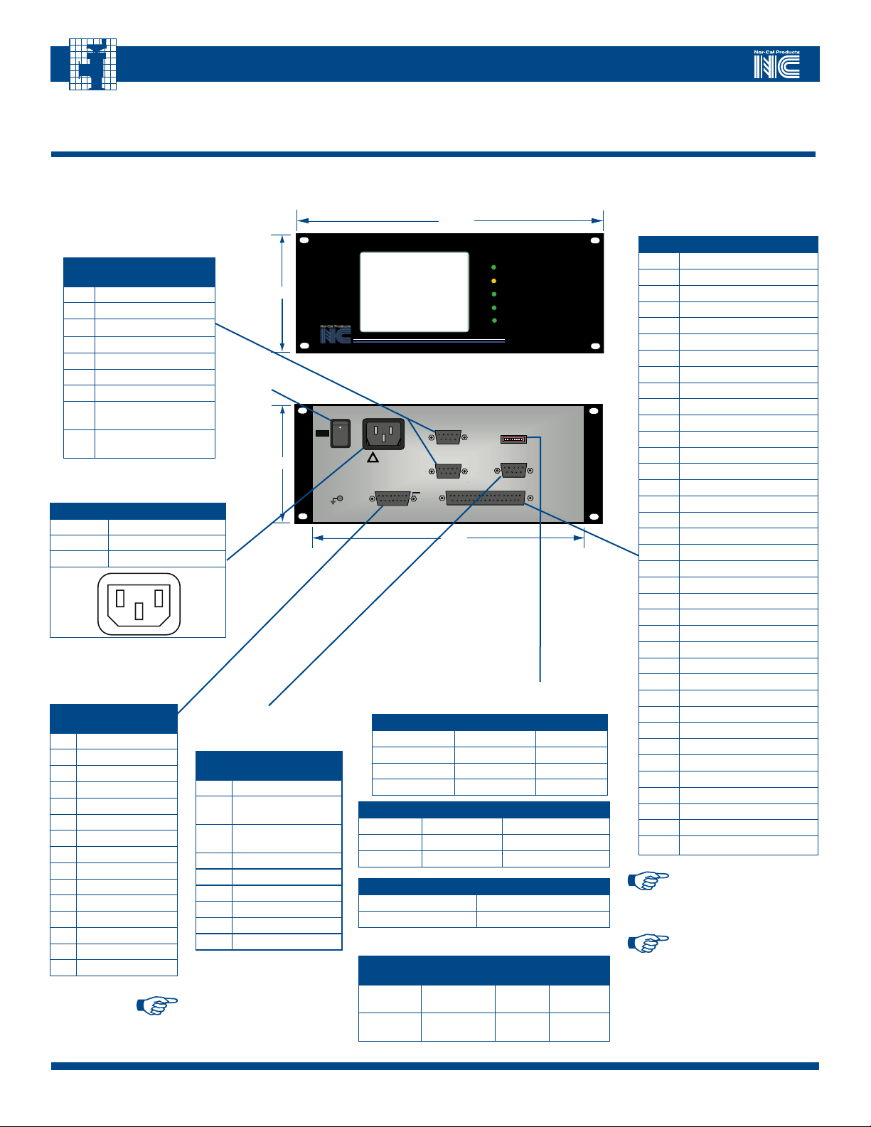
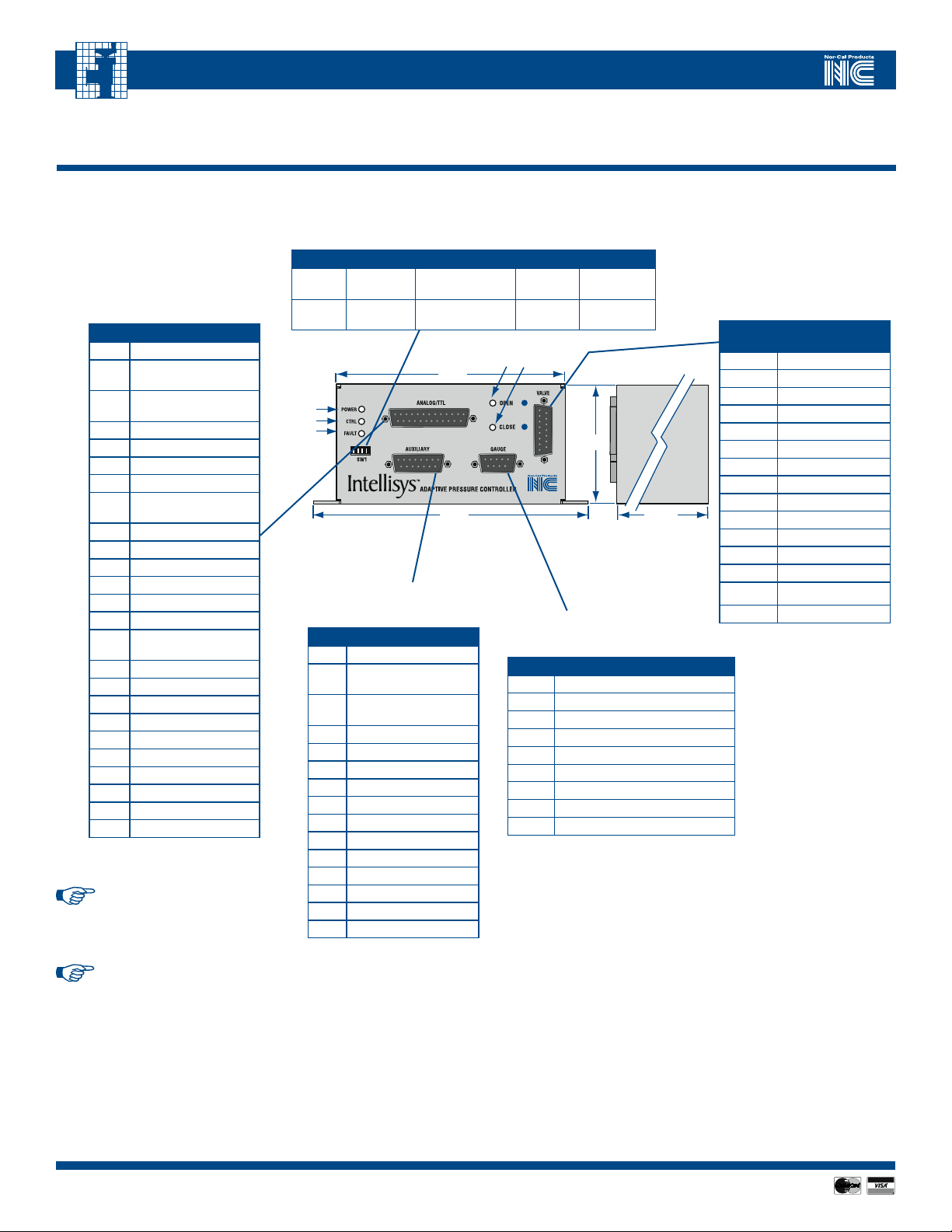
3.2 - A/C Powered Buried Box Controllers Interface
Refer to the following diagrams and tables when connecting to an A/C powered APC Buried Box Controller including models APC-100-A, APC-200-A, APC-300-A, APC-
700-A and APC-800-A.
TABLE 3.2.1 - (J3 & J4)
“APC-X00-A” GAUGE
CONNECTOR DB-9 RECEPTACLE
(IDENTICAL PINOUTS)
SIGNAL
PIN
ASSIGNMENT
1 Signal input from gauge
2 N/C
3 N/C
4 +15VDC output to gauge
5 -15VDC output to gauge
6 N/C
7 N/C
Signal common from
8
gauge
Power common
9
output to gauge
TABLE 3.2.2 - (J1) “APC-X00-A” A/C
POWER CONNECTOR
PIN FUNCTION
1 Neutral
2 Ground
3 Line in 100 to 240 VAC
2
1 3
TABLE 3.2.3 - (J5)
“APC-X00-A” VALVE
CONNECTOR,
DB-15 RECEPTACLE
SIGNAL
PIN
ASSIGNMENT
1 Drive A+
2 Drive A3 Drive B4 Drive B+
5 Sense B6 Sense B+
7 Sense A8 Sense A+
9 Reserved
10 Reserved
11 Reserved
12 Reserved
13 Reserved
14 Reserved
15 Reserved
NOTE: Function \names\ with a
backward slash indicate active low
input or output signals
Power
On/Off
Switch
TABLE 3.2.4 - (J2) “APC-X00-A” RS-
232 SERIAL PORT, DB-9 RECEPTACLE
SIGNAL
PIN
ASSIGNMENT
1 RS485 (B)
RS-232 TX (data from
2
APC to host)
RS-232 RX (data from
3
host to APC)
4 N/C
5 Signal Common
6 N/C
7 N/C
8 N/C
9 RS485 (A)
Status LEDs
Valve
Open/Close
Switch
Momentary
TABLES 3.2.5 - (SW1) “APC-X00-A” DIP SWITCH
SETTINGS FOR SERIAL COMMUNICATIONS
BAUD RATE SWITCH 1 SWITCH 2
19200 OFF (up) OFF (up)
9600 ON (down) OFF (up)
4800 OFF (up) ON (down)
1200 ON (down) ON (down)
PARITY SWITCH 3 SWITCH 4
None OFF (up) Either ON or OFF
Odd ON (down) OFF (up)
Even ON (down) ON (down)
STOP BITS* SWITCH 5
1 OFF (up)
2 ON (down)
* If parity is enabled (either odd or even) then only 1 stop bit is
used and SW1 position 5 will be ignored
OTHER
FUNCTIONS
ON (down)
OFF (up) RS-232
SWITCH 6SWITCH 7SWITCH
8
Enable
RS-485
Analog S.P.
0-5 VDC
Analog S.P.
0-10 VDC
Reserved
Reserved
(J6) “APC-X00-A”ANALOG / TTL
CONNECTOR, DB-37 RECEPTACLE
PIN FUNCTION
10 \Analog Div 10 Select In\
11 \Analog SP Control Select In\
12 Digital GND / RS232 Common
13 TTL Out Common
14 N/C
15 N/C
16 N/C
17 N/C
18 Analog Valve Out (0-5 VDC)
19 \Valve Open Out\
20 N/C
21 N/C
22 N/C
23 \Valve Closed Out\
24 Fault Out
25 \Zero Gauge Select In\
26 See NOTE below
27 \Open Valve In\
28 PLO #2 Status
29 PLO #1 Status
30 N/C
31 N/C
32 N/C
33 Analog SP+ In
34 Analog SP- In
35 Analog GND
36 Analog CDG Out
37 Analog Valve Out
300- series controllers,
pin 26 is defined as
\Hold Valve Select In\
800- series controllers,
pin 26 is defined as
\Valve Initialization
Enable In\
TABLE 3.2.6 -
1 N/C
2 N/C
3 N/C
4 Digital GND / RS232 Common
5 \CDG2 Select In\
6 \Position Control Select In\
7 N/C
8 \Close Valve In\
9 \Control Active Out\
NOTE: For 100-, 200- &
NOTE: For 700- &
APC-OP-LIT 1/12
88
Visit our Web Site www.n-c.com
Page 9
IntellIsys AdAptIve pressure Controllers
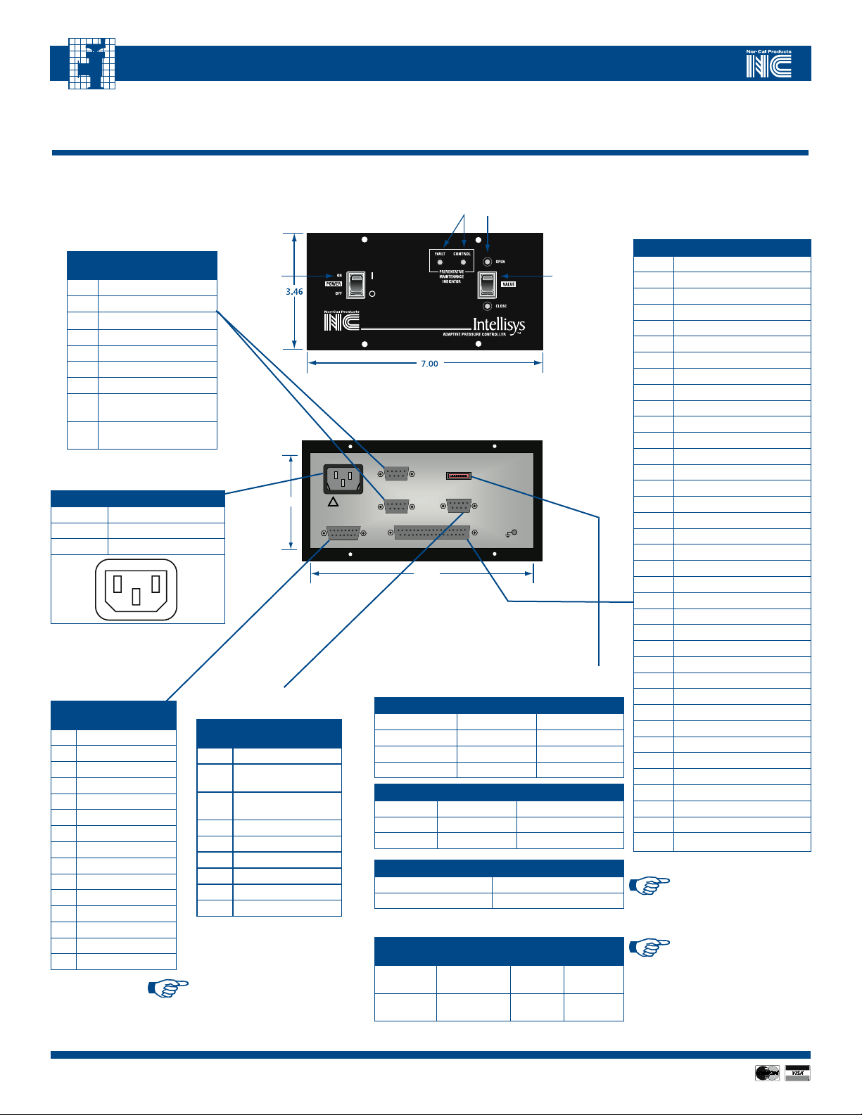
3.3 - DC Powered Controllers with Serial I/O Interface
Refer to the following diagram and tables when connecting to a DC powered APC controller including model APC-800L-A-S01.
TABLE 3.3.1 - (J1)
“APC-800L-A-S01”
GAUGE CONNECTOR,
DB-15 RECEPTACLE
PIN FUNCTION
1
Chassis GND
2
Chassis GND
3
N/C
4
Signal common from gauge 2
5
Signal input from gauge 2
6
N/C
7
Signal common from gauge 1
8
Signal input from gauge 1
9
+15V supply to gauge
10
+15V supply to gauge
11
Power Supply Common
12
Power Supply Common
13
N/C
14
-15V supply to gauge
15
-15V supply to gauge
(J2) “APC-800L-A-S01” POWER
TABLE 3.3.2 -
CONNECTOR, DB-9 PLUG
PIN FUNCTION
1
Chassis GND
2
Power RTN
3 Power RTN
Power +24V IN
4
5
Power +24V IN
6
N/C
7
N/C
8
N/C
9
N/C
Status
LED
POWER
Status LEDs
4.15
TABLE 3.3.3 -
(J4) “APC-800L-A-S01” VALVE
CONNECTOR, DB-15 PLUG
SIGNAL
PIN
ASSIGNMENT
1
2
3
4
5
6
7
8
9
10
11
12
13
14
15
I/O
Drive A+
Drive A-
Drive BDrive B+
Sense B-
Sense B+
Sense A-
Sense A+
Reserved
Reserved
Reserved
Reserved
Reserved
Reserved
Reserved
TABLE 3.3.4 -
(J3) “APC-800L-A-S01” I/O
CONNECTOR,
DB-15 RECEPTACLE
PIN FUNCTION
1
Chassis GND
RS-232 TX (data from
2
APC to host), or 485A
RS-232 RX (data from
3
host to APC), or 485B
4
N/C
5
N/C
6
N/C
7
Digital GND
8
N/C
9
N/C
10
N/C
11
N/C
12
Valve Closed input
13
Digital GND
14
\Valve Closed Output\
15
TTL Output Common
5.12
2.49
5.95
APC-OP-LIT 1/12
Call toll free 800-824-4166 or 530-842-4457 • FAX 530-842-9130
9
Page 10
IntellIsys AdAptIve pressure Controllers
Status LEDs
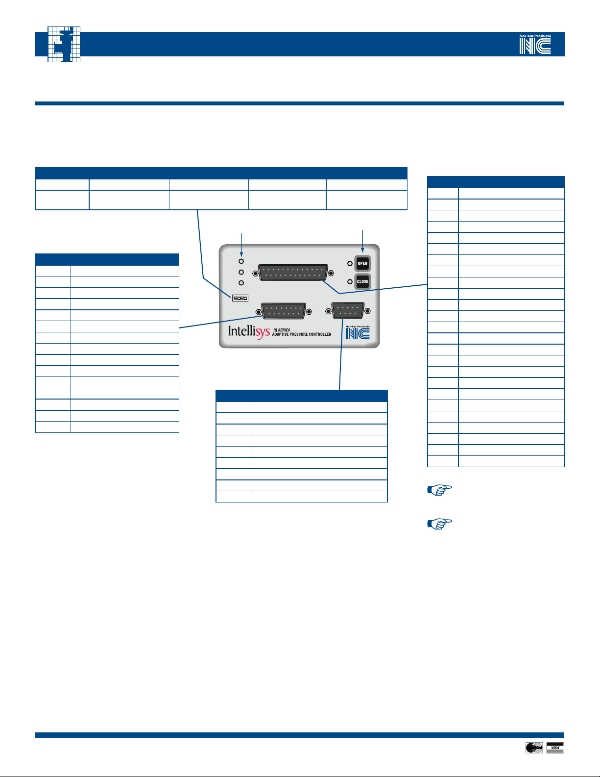
3.4 – DC Powered Controllers with Serial and Analog/TTL I/O Interface
Refer to the following diagram and tables when connecting to a DC powered APC controller
including models APC-100L-A, APC-200L-A, APC-300L-A, APC-700L-A and APC-800L-A.
TABLE 3.4.2 - (SW1) “APC-X00L-A” DIP SWITCHES
SWITCH 1 SWITCH 2 SWITCH 3 SWITCH 4
TABLE 3.4.1 – (J4) “APC-X00L-A”
ANALOG / TTL CONNECTOR,
DB-25 RECEPTACLE
PIN FUNCTION
1
Chassis GND
RS-232TX (data from IQ
2
to host)
RS-232RX (data from
3
host to IQ)
4
Analog CDG Out
5
Analog GND
6
Analog Valve Out
7
Digital GND
\Analog SP Control
8
Select In\
9
Analog SP+ In
10
Analog SP- In
11
Power RTN
12
Power 24V in
13
\CDG2 Select In\
14
See NOTE below
\Position Control Select
15
In\
16
N/C
17
Analog GND
18
\Close Valve In\
19
\Open Valve In\
20
Fault Out
21
N/C
22
\Valve Open Out\
23
\Valve Closed Out\
24
TTL Out Common
25
Chassis GND
NOTE: For 100L-A, 200L-A
and 300L-A series controllers, pin
14 is defined as \Hold Valve Select In\
OFF (up)
ON (down)
9600 baud 8 bit, no parity 1 stop bit
19200 baud
Status
LEDs
TABLE 3.4.4 - (J3) “APC-X00L-A”
AUXILIARY CONNECTOR,
DB-15 RECEPTACLE
PIN FUNCTION
1
Not used
RS-232 TX (data from IQ
2
to host)
RS-232 RX (data from
3
host to IQ)
4
Digital GND
5
Power RTN
6
Not used
7
Power +24V in
8
Not used
9
Analog CDG Out
10
Analog Valve Out
11
Analog GND
12
TTL Out Common
13
\Valve Open Out\
14
\Valve Closed Out\
15
Chassis GND
7 bit, even parity
(1 stop bit only)
4.78
5.74
2 stop bits
PIN FUNCTION
1
2
3
4
5
6
7
8
9
0-10 V Analog
in
0 to 5V
Analog in
2.51
5.69
TABLE 3.4.5 - (J2) “APC-X00L-A”
GAUGE CONNECTOR,
DB-9 RECEPTACLE
Signal input from gauge 1
+15 V supply to gauge
-15 V supply to gauge
Not used
Signal input from gauge 2
Signal common from gauge 2
Not used
Signal common from gauge 1
Power supply common
TABLE 3.4.3 - (J1) “APC-X00L-A”
VALVE CONNECTOR,
DB-15 RECEPTACLE
PIN
1 Drive A+
2 Drive A3 Drive B4 Drive B+
5 Sense B6 Sense B+
7 Sense A8 Sense A+
9 Reserved
10 Reserved
11 Reserved
12 Reserved
13 Reserved
14 Reserved
15 Reserved
SIGNAL
ASSIGNMENT
NOTE: For 700L-A and 800L-A
series controllers, pin 14 is
defined as \Valve Initialization
Enable In\
1010
APC-OP-LIT 1/12
Visit our Web Site www.n-c.com
Page 11
IntellIsys AdAptIve pressure Controllers
2.51
5.74
5.69
4.78
Indicating LEDs
1
4
3
2
5
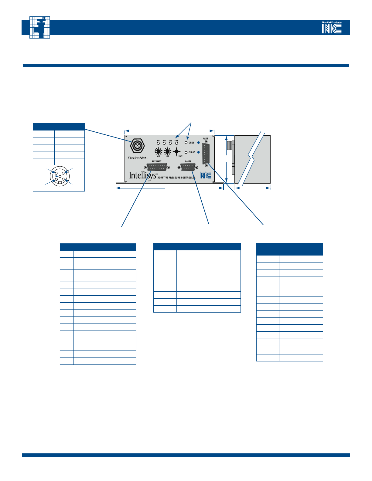
3.5 - DC Powered Controllers with Serial and DeviceNet I/O Interface
Refer to the following diagrams and tables when connecting to an D/C powered APC controller including models APC-100L-D, APC-200L-D, APC-300L-D, APC-700L-D and
APC-800L-D.
TABLE 3.5.1 –
(J1) “APC-X00L-D”
DEVICENET NETWORK
CONNECTOR
PIN FUNCTION
1
Drain
2
Power In +
3
Power In -
4
CAN H
5
CAN L
TABLE 3.5.2 – (J2) “APC-X00L-D”
AUXILIARY CONNECTOR,
DB-15 RECEPTACLE
PIN FUNCTION
1
Not used
RS-232 TX (data from IQ to
2
host)/485 (A)
RS-232 RX (data from host to
3
IQ)/485 (B)
4
Digital GND
5
Power RTN
6
Not used
7
Power +24V in
8
Not used
9
Analog CDG Out
10
Analog Valve Out
11
Analog GND
12
TTL Out Common
13
\Valve Open Out\
14
\Valve Closed Out\
15
Chassis GND
TABLE 3.5.3 – (J3) “APC-X00L-D”
GAUGE CONNECTOR,
DB-9 RECEPTACLE
PIN # FUNCTION
1
Signal input from gauge 1
2
+15 V supply to gauge
3
-15 V supply to gauge
4
Not used
5
Signal input from gauge 2
6
Signal common from gauge 2
7
Not used
8
Signal common from gauge 1
9
Power supply common
TABLE 3.5.4 - (J4) “APC-X00L-D”
VALVE CONNECTOR,
DB-15 RECEPTACLE
PIN
1 Drive A+
2 Drive A3 Drive B4 Drive B+
5 Sense B6 Sense B+
7 Sense A8 Sense A+
9 Reserved
10 Reserved
11 Reserved
12 Reserved
13 Reserved
14 Reserved
15 Reserved
SIGNAL
ASSIGNMENT
Call toll free 800-824-4166 or 530-842-4457 • FAX 530-842-9130
APC-OP-LIT 1/12
11
Page 12
IntellIsys AdAptIve pressure Controllers
3.6 – DC Powered IQA Controlled Valve with Serial and Analog/TTL I/O Interface
Refer to the following diagram and tables when connecting to an IQA controller
including models TBV-IQA, TSS-IQA and TPV-IQA.
OFF (up)
ON (down)
TABLE 3.6.2 – (J3) “IQA”
AUXILIARY CONNECTOR,
DB-15 RECEPTACLE
PIN FUNCTION
1
Not used
2
RS-232 TX (data from IQ to host)
3
RS-232 RX (data from host to IQ)
4
Digital GND
5
Power RTN-
6
Not used
7
Power +24V in
8
Not used
9
Analog CDG Out
10
Analog Valve Out
11
Analog GND
12
TTL Out Common
13
\Valve Open Out\
14
\Valve Closed Out\
15
Chassis GND
TABLE 3.6.1 – (SW1) “IQA” DIP SWITCHES, DB-25 RECEPTACLE
SWITCH 1 SWITCH 2 SWITCH 3 SWITCH 4
9600 baud 8 bit, no parity 1 stop bit 0 to 10 V Analog In
19200 baud
7 bit, even parity
(1 stop bit only)
POWER
Indicating
LEDs
CTRL
FAULT
SW1
2 stop bits 0 to 5 V Analog In
Valve Open/Close
membrane switches
ANALOG/TTL
AUXILIARY
TM
GAUGE
TABLE 3.6.3 – (J2)
“IQA” GAUGE CONNECTOR,
DB-9 RECEPTACLE
PIN # FUNCTION
1
Signal input from gauge 1
2
+15 V supply to gauge
3
-15 V supply to gauge
4
Not used
5
Signal input from gauge 2
6
Signal common from gauge 2
7
N/C
8
Signal common from gauge 1
9
Power supply common
TABLE 3.6.4 – (J4) “IQA”
ANALOG/TTL CONNECTOR,
DB-25 RECEPTACLE
PIN FUNCTION
1
Chassis GND
2
RS-232TX (data from IQ to host)
3
RS-232RX (data from host to IQ)
4
Analog CDG Out
5
Analog GND
6
Analog Valve Out
7
Digital GND
8
\Analog SP Control Select In\
9
Analog SP+ In
10
Analog SP- In
11
Power RTN
12
Power +24V in
13
\CDG2 Select In\
14
See NOTE below
15
\Position Control Select In\
16
N/C
17
Analog GND
18
\Close Valve In\
19
\Open Valve In\
20
Fault Out
21
N/C
22
\Valve Open Out\
23
\Valve Closed Out\
24
TTL Out Common
25
Chassis GND
NOTE: When IQA is installed on a
TBV valve, pin 14 is defined as \Hold
Valve Select In\
NOTE: When IQA is installed on a
TPV or TSS valve, pin 14 is defined
as \Valve Initialization Enable In\
1212
APC-OP-LIT 1/12
Visit our Web Site www.n-c.com
Page 13
IntellIsys AdAptIve pressure Controllers
1
4
3
2
5
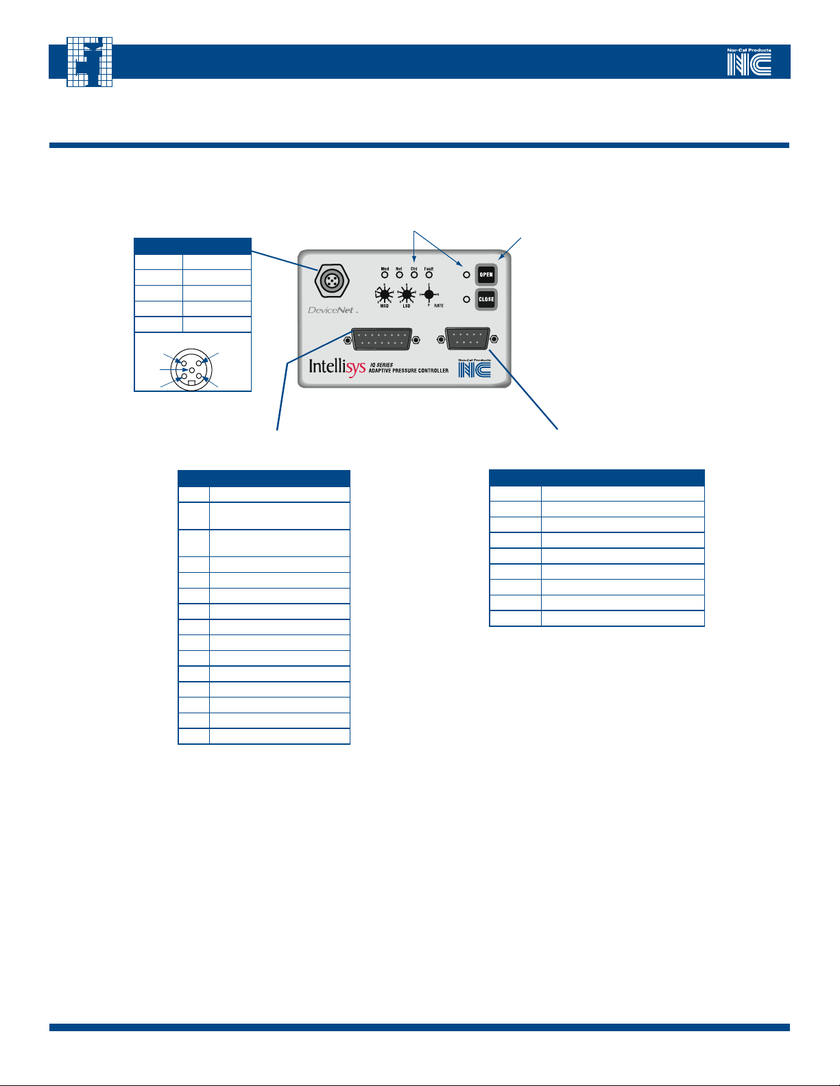
3.7 - DC Powered IQD Controlled Valve with Serial and DeviceNet I/O Interface
Refer to the following diagram and tables when connecting to an IQD controller including models TBV-IQD, TSS-IQD and TPV-IQD.
TABLE 3.7.1 –
(J1) “IQD” DEVICENET
NETWORK CONNECTOR
PIN FUNCTION
1
Drain
2
Power In +
3
Power In -
4
CAN H
5
CAN L
Indicating LEDs
AUXILIARY
TM
Valve Open/Close
membrane switches
GAUGE
TABLE 3.7.2 – (J2) “IQD”
AUXILIARY CONNECTOR,
DB-15 RECEPTACLE
PIN FUNCTION
1
Not used
RS-232 TX (data from IQ to
2
host)/485 (A)
RS-232 RX (data from host to
3
IQ)/485 (B)
4
Digital GND
5
Power RTN
6
Not used
7
Power +24V in
8
Not used
9
Analog CDG1 Out
10
Analog Valve Out
11
Analog GND
12
TTL Out Common
13
\Valve Open Out\
14
\Valve Closed Out\
15
Chassis GND
TABLE 3.7.3 – (J3) “IQD”
GAUGE CONNECTOR,
DB-9 RECEPTACLE
PIN # FUNCTION
1
Signal input from gauge 1
2
+15 V supply to gauge
3
-15 V supply to gauge
4
Not used
5
Signal input from gauge 2
6
Signal common from gauge 2
7
Not used
8
Signal common from gauge 1
9
Power supply common
APC-OP-LIT 1/12
Call toll free 800-824-4166 or 530-842-4457 • FAX 530-842-9130
13
Page 14
IntellIsys AdAptIve pressure Controllers
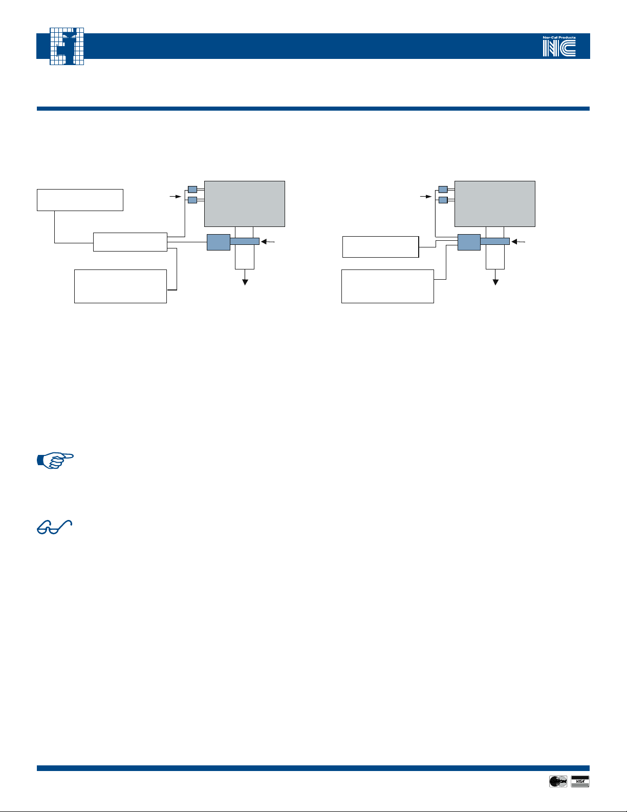
4.0 - Theory of Operation
All APC controllers are designed for downstream pressure control (see Fig 4.1 and 4.2). As such, it is one of four important components in a pressure
control system. The other three essential components include a host system computer, a throttle valve and one or two vacuum gauges, such as a
Capacitance Diaphragm Gauge (CDG). Most manufacturers’ vacuum gauges can be used to provide the vacuum measurement signal, provided
they have a voltage output proportional to pressure.
AC or DC power supply
APC Controller
Host system with
RS232/485 or DeviceNet
communications
FIGURE 4.1 – TYPICAL INSTALLATION AND CONFIGURATION OF A BURIED
BOX INTELLISYS DOWNSTREAM PRESSURE CONTROL SYSTEM
Vacuum
gauge(s)
Vacuum Chamber
Pump
Nor-Cal
throttle
valve
Initialization Sequence
When first powered up, the APC controller will run the valve through an
initialization sequence that lasts for approximately 30 seconds. The primary
purpose for this operation is for the controller to determine the fully open
and closed points, as well as for certain motor and position calibration steps
to occur. While the initialization sequence is active, the amber FAULT light will
be illuminated and the OPEN/CLOSE LEDs will blink in an alternating fashion.
Once the initialization sequence is complete, the valve will move to the fully
open position and the green OPEN LED will illuminate.
NOTE: The controllers for TPV pendulum valves and TSS
gate valves contain a valve initialization safety lock function.
This safety lock will prevent valve initialization to occur until
given a “clear-to-proceed” command. The RS-232 serial
command for this is JC. Alternatively, the \Valve Initialization
Enable In\ TTL pin can be pulled low to initiate this sequence.
CAUTION: Never attempt to initialize a throttle valve with
differential pressure across the sealing gate. Make sure the
pressure on both sides is equalized. Damage to pumps and
other equipment can occur otherwise.
Vacuum
gauge(s)
DC power supply
Host system with
RS232/485 or DeviceNet
communications
FIGURE 4.2 – TYPICAL INSTALLATION AND CONFIGURATION
OF AN IQ PRESSURE CONTROL VALVE
Vacuum Chamber
Pump
Nor-Cal
IQ-series
Valve
Normal Operation
After the initialization sequence is complete normal operation of the valve is
possible. There are two primary modes of operation, a) position control mode
and b) pressure control mode.
In position control mode, the valve will move to any position in its range
based on a position set-point command from the host. The valve will remain
in that position until instructed to do otherwise. Position control mode can
be useful in certain cases where pre-determined amount of baffling or
throttling is necessary.
Pressure control mode, on the other hand, is used whenever control to a
specific system pressure level is desired. The host provides the set-point value
to the controller which, in turn, moves the valve to achieve that set point as
quickly as possible. During pressure control mode, external perturbations
such as flow changes and plasma events will automatically be compensated
for by the controller so that the pressure set-point is maintained. The set
point value can be changed by the host at any time.
Tuning
The APC controller contains an Adaptive Pressure Control Algorithm that
has been designed to work over a wide range of flow and pressure combinations. The APC controller therefore does not have a “learn mode” and there
is no need for the user to set PID parameters. In some instances, however,
vacuum system design may affect the closed loop pressure control time
constants. As a result, pressure control performance may at times be
affected. If satisfactory pressure control cannot be achieved with the
Adaptive Pressure Control Algorithm, please contact Nor-Cal Products’
Intellisys Customer Support.
1414
APC-OP-LIT 1/12
Visit our Web Site www.n-c.com
Page 15

IntellIsys AdAptIve pressure Controllers
5.0 - APC Controller Module Interfaces
APC controllers have several interfaces available for communications and connectivity to peripheral devices, depending on model. These are described by function below. Please also refer to Figures 3.1 – 3.5 and their associated Tables for the specific connectors and their pin assignments.
Vacuum Gauge Interface
The pressure signal from one or two vacuum gauges can be interfaced to the
APC controller module through the connector labeled GAUGE, or CDG1 and
CDG2 depending on the model. In addition, ±15 VDC is available to power
such gauges from these ports.
NOTE: If the power requirement of the gauge(s) used
exceeds the rated power output, then a separate power
source must be used.
When only one gauge is used, then the pressure signal must be connected to
the CDG1+ and CDG1- signal pins. Use of two gauges requires adhering to
the following steps:
1. The full scale range of the two gauges used must be at least one but
no more than four decades (factors of ten) apart.
2. Only 1 gauge is active at a time.
Analog and TTL Interface (not available on all models)
For complete control and monitoring purposes using a PLC or A/D communications PC cards, several analog I/O signals as well as a host of discrete (TTL)
I/O contacts are made available through the connectors labeled ANALOG/TTL
or I/O, depending on model. The analog inputs and outputs are referenced to
the analog output common, and are factory set as 0 to 10 Volt signals, though
a 0 to 5 volt range can be selected via the dip-switch. All analog I/O is
calibrated to within 10 mV.
All TTL outputs are active low signals except for the FAULT function, which is
active high. TTL inputs are diode protected at –0.4 VDC. Maximum low input
voltage is 0.6V and the minimum sink current is 1 mA. The minimum high
input voltage is 2.5V, or open. TTL outputs are optically isolated and rated at
25V max and 10 mA. TTL inputs are referenced to the Digital Ground (pin #7),
whereas the TTL outputs are referenced to TTL Out Common on pin #24.
On some controller models, certain functions and signals are available on
more than one connector. This is to give the user a choice of how to connect
the device, and also to offer the capability for in-situ monitoring without
disconnecting the main interface cables
Serial interface
An RS-232 serial interface is available on all controller models, through one or
more ports. Please refer to the Section 6.0 for a full description of the com-
munications protocol and a listing of all active serial commands. A three-wire
connection completes the communications consisting of Rxd (data from the
APC), Txd (data to the APC) and digital ground.
are neither needed nor available.
settings are 9600 Baud, 1 stop bit and no parity. These settings
can only be changed on models with DIP switches, and changing
the setting requires cycling APC input power off then back on.
Every serial input command sent by the HOST has an end-of-line delimiter, carriage return ASCII 0x0D [hex], or the line feed character ASCII 0x0A [hex], or
the carriage return and line feed character in that order. The APC-device endof-line delimiter is the carriage return and line feed characters.
NOTE: CTS, RTS and DSR connections
NOTE: The default factory RS-232 communications parameter
DeviceNet Interface (not available on all models)
The five-pin circular DeviceNet port allows for complete remote control,
monitoring and power supply of the APC controller in a cost effective and reliable way. In addition to the connector are two status LEDs labeled Mod and
Net, as well as three rotary switches labeled MSD, LSD and RATE. A complete
explanation of the DeviceNet physical and software interfaces can be found in
Sections 8 and 9.
Indicating LEDs
There are a host of indicating LEDs on the APC controller, depending on
model. In general, the green Power LED is illuminated whenever power is
applied to the device. The green Ctrl LED is illuminated whenever the APC is
in set point control (pressure or position). The amber Fault LED is illuminated
briefly during the initialization sequence after power-up but primarily if the
APC device enters a fault state. Two LEDs usually are located adjacent to the
OPEN and CLOSE switches or labels, and are illuminated whenever the valve
position is within 2% of either limit.
Switches
Some controller models have a bank of four or eight dip switches labeled SW1.
These are principally used for serial communications settings and selecting 0-5
VDC analog input. A switch in the “up position” (relative to the text) is OFF,
and dip switch #1 is always in the left most position. Please refer to the tables
in Section 3 for a complete listing of valid dip switch settings.
Primarily intended for operation during installation or troubleshooting, some
APCs also feature two momentary switches that can be used to drive the valve
fully open or closed. To prevent inadvertent valve operation, these switches
cannot be used if the APC valve is in Control Mode (green Ctrl LED on).
Call toll free 800-824-4166 or 530-842-4457 • FAX 530-842-9130
APC-OP-LIT 1/12
15
Page 16

IntellIsys AdAptIve pressure Controllers
6.0 - RS-232 Serial Interface and Commands
Interface basics
All APC controllers support RS-232 serial communications available though one or more interface ports. A full description of the communications protocol and
a listing of all active serial commands follows in this section. But first, a three-wire connection needs to be completed to provide the communications lines, with
Rxd (data from the APC), Txd (data to the APC) as well as signal common on.
NOTE: Hardware handshaking is not available.
NOTE: The default factory RS-232 communications parameter settings are 9600 Baud, 1 stop bit, no parity and 8-bit character.
These settings can only be changed on models with DIP switches, and changing the setting requires cycling APC input power off then back on.
Every serial input command sent by the HOST has an end-of-line delimiter, carriage return ASCII 0x0D [hex], or the line feed character ASCII 0x0A [hex],
or the carriage return and line feed character in that order. The APC-device end-of-line delimiter is the carriage return and line feed characters.
Serial Commands Summary
Table 6.1 and 6.2 summarize the serial commands and responses available with the APC controller. Additional commands
may be included to enable customer specific functions. Please contact Nor-Cal Products Intellisys Customer Support for more details.
TABLE 6.1 – RS-232 SERIAL COMMANDS
SERIAL
COMMAND DESCRIPTION
C Close the valve Same function as pressing the CLOSE button
O Open the valve Same function as pressing the OPEN button
H Hold the valve in the current position Stops active pressure control, if device is in that mode
T1x
S1xx.xx
D1 Activates set-point #1. Put the device in control mode, effectively making the setpoint active.
Vxx.xx Go to valve position xx.xx is 0 to 100% of full open
L0 Auto select CDG1 or CDG2 for best resolution Default two gauge configuration.
L1 Control to and report CDG1 values only Selects Gauge 1 for manitenance function.
L2 Control to and report CDG2 values only Selects Gauge 2 for manitenance function.
N1xx Sets the full scale range of CDG1 Values for xx can be found in Table 6.3
N2xx Sets the full scale range of CDG2 Values for xx can be found in Table 6.3
JC
Sets the type of set point #1. When x=0, the set-point type is position.
When x=1, the set-point type is pressure.
Used to program a value for set point xx.xx is any number between 0.00 and
100.00, representing the % of gauge full scale
Clears the “initialization safety lock feature” included on some TPV and TSS
controllers
RS-232 Commands Examples
The following section provides examples of the most commonly used commands and responses. The APC serial command protocol is not case sensitive, though
all the command examples in this section are listed in capital letters. Furthermore, whenever necessary the character Ø has been used to designate the number
zero, so as to not confuse it with the letter O.
TABLE 6.2 – RS-232 SERIAL REQUESTS AND RESPONSES
SERIAL
REQUEST DESCRIPTION
R1
R5
R6
R38
R26
GSN
RN1
RN2
RESET
Requests the set point value S1 + xx.xx, where xx.xx is a number from 0.00 to 100.00
Requests the current pressure P+xx.xx, where xx.xx is a number from 0.00 to 100.00
Requests the current valve position V +xx.xx, where xx.xx is a number from 0.00 to 100.00
Requests the software version APC3-[version #] [version date]
Report set point type
Get the serial number of the device Serial nb xxxxxx
Requests full scale range of CDG1 N1xx.xx, where xx.xx is the full scale range of CDG1
Requests full scale range of CDG2 N2xx.xx, where xx.xx is the full scale range of CDG2
Resets the device Same as cycling power
NOTES /
EXAMPLES
S150, for example, programs the value of 50% for the setpoint. When using
a 1 Torr gauge, this corresponds to 500 mTorr..
Initializes Valve
RESPONSE
T1x, When x=0, the set-point type is position. When x=1, the set-point type
is pressure.
1616
APC-OP-LIT 1/12
Visit our Web Site www.n-c.com
Page 17

IntellIsys AdAptIve pressure Controllers
6.0 - RS-232 Serial Interface and Commands (continued)
Modifying the Setpoint
The APC controller normally has five programmable set point selectable
to be either pressure control or valve position control. Before using the set
point to control either pressure or valve position, the set point value must
be programmed. This is done by the following command:
S1xx.xx where xx.xx is a number from 0.00 to 100.00.
One or no decimal places may also be used i.e. x.x or x.
Reading the Setpoint
The set point can be read back to the Host
controller only through the serial port.
R1 To verify the set point
The IQ controller will respond with
S1+xx.xx where xx.xx is the set point value.
Selecting Valve Position Control or Pressure Control
The set point input value is common for both valve position and pressure
control. Therefore, it is necessary to program the APC so that it controls
to the correct type. The factory default setting is pressure control.
To assign the set point control type and source,
send the following commands:
TØØ
Analog STPT input, position control
TØ1 (T02, T03, T04, T05)
Digital STPT 1 (2, 3, 4, or 5 if present), postion control
T1Ø
Analog STPT input, pressure control
T11 (T12, T13, T14, T15)
Digital STPT 1 (2, 3, 4, or 5 if present), pressure control
Verifying the Control Mode
Before starting either pressure control or position control operations it
might be necessary to verify the setting of the set point type. This can
only be accomplished through the serial port with the command
R25
Analog STPT
R26
The IQ controller responds with:
T1x where x is Ø for position control or 1 for pressure control (default).
How to Control Valve Position
One of the two main functions of the APC controller is Valve Position Control.
In this mode the APC controller will simply move the throttle valve plate to a
prescribed position according to a set point. The set point is a value between
0% and 100%, where 0% is closed and 100% is open.
OPEN: The serial command is O.
The controller will only respond by opening the valve.
CLOSE: The serial command is C.
The controller will only respond by closing the valve.
HOLD: The serial command is H. The controller will
only respond by stopping the valve at the current position.
Any Valve Position: Vxx.xx where xx.xx is a number from
0.00 to 100.00% of full open. One or no decimal places
may also be used i.e. x.x or x.
Similarly use the T1Ø command to set the set point type to position control.
Then follow the information outlined in the How To Modify the Setpoint and
How To Control System Pressure sections.
Reading the Valve Position
The valve position may also be obtained through the serial port.
The valve position is reported as a % of full open using the command:
R6
The Controller responds with the valve position using the format:
Vxx.xx where xx.xx is a number from 0.00 to 100%
of valve open position.
How to Control System Pressure
The principal function of the APC controller is to control system pressure.
To accomplish this, the APC controller needs to be put in “pressure control
mode” while being supplied a pressure set point. The pressure set point is
proportional to the vacuum gauge’s full scale range.
Controlling pressure using the serial port provides additional flexibility.
To activate a set point issue the command:
D1
The active set point must be set to the correct value before activating the
pressure control set point. The set point can be modified any time before, during, or after pressure control. Also a different set point can be activated
at any time.
Reading System Pressure
Pressure, as output by the system gauge(s) to the APC Controller,
can be read directly from the controller. Both the signals from
CDG1 and CDG2 can be read independently.
The APC controller will report the pressure via
the serial port with the following command:
R5
The controller will respond with:
P+xx.xx where + indicates the polarity of
the value and xx.xx is a value.
The range of xx.xx is typically from 0.00 to 100.00 and represents the pressure
as a percentage of the full scale of the pressure gauge. The value can be less
than 0 if the vacuum gauge electronics have drifted or greater than 100 but
limited to 101.5%. For example, it the system uses a 100 Torr gauge and the
pressure is actually 10 Torr, the controller response will be P+10.00. On the
other hand, if the pressure is 10 Torr but the system has a 20 Torr gauge, the
controller response will be P+50.00.
When two CDG’s are used, the APC controller will always report the
pressure as a percentage of the high range gauge. For example, if the
system has a 100 Torr gauge attached to CDG1 and a 1 Torr gauge attached
to CDG2 and the actual system pressure is 0.1 Torr the response to the
R5 command will be P+0.100.
APC-OP-LIT 1/12
Call toll free 800-824-4166 or 530-842-4457 • FAX 530-842-9130
17
Page 18

IntellIsys AdAptIve pressure Controllers
6.0 - RS-232 Serial Interface and Commands (continued)
Activating Dual Pressure Sensor Configuration
When two pressure gauges are attached to the APC controller, the controller
can operate in three distinct modes of operation.
Dedicated to the first gauge:
(This is the power-on default mode)
In that mode the controller only considers CDG1 for pressure control
as well as reporting. This mode is initiated by the L1 command
Dedicated to the second gauge:
In that mode the controller only considers CDG2 for pressure control
as well as reporting. This mode is initiated by the L2 command
The L1 and L2 command are particularly relevant to dual chamber
systems venting to one single downstream exhaust valve. In that situation
there are two distinct pressure gauges corresponding to each individual
vacuum chamber. The APC controller is then used alternatively control
pressure in each chamber.
Dual range mode:
LØ activates this mode, in which the controller utilizes the two gauges to
optimize the pressure measurement. Two gauges are intended to be complementary in covering the dynamic pressure range. The high gauge is referred to
as the primary gauge. The low gauge is designed to be the secondary gauge
covering the low range measurements. In dual range mode gauges can be
switched. The gauge range needs to be predefined as illustrated in the next
section. The APC controller will use the range information to determine the
pressure at which the controller will switch from reading one CDG to another.
The automatic switch over is at 90% of the full scale value of the lower range
gauge when the pressure is decreasing and greater than 99% of the full scale
value of the lower range gauge when the pressure is increasing. Please note
that in Dual Range Mode, all set point commands are with respect to the primary gauge range (CDG1).
How to Configure Pressure Sensor Parameters
When two pressure gauges are used it is necessary to program the APC
with sufficient information so that it knows the full scale of each gauge
and, hence, the ratio of the full scale pressure ranges. The factory default
full-scale range for CDG1 is 10 Torr, and that for CDG2 is 0 Torr ( not connected).
TABLE 6.3 – VALUES FOR XX FOR
USE WITH DUAL RANGE MODE
CDG1 OR
CDG2
FULL SCALE
(IN TORR)
0.1 0.1
0.2 0.2
0.5 0.5
1 1
2 2
5 5
10 10 (CDG1 default)
50 50
100 100
500 500
1000 1000
0
VALUE
OF
XX
Not connected
(CDG2 default)
gauge full scale range is not
necessary when only one
gauge is installed.
First, program the full scale
range of CDG1 using:
N1xx where xx is the number found
in Table 6.3 describing the full scale
range of CDG1. For example, enter
N100 if CDG 1 is a 100 Torr gauge.
Then, program the CDG2 full scale
range with:
N2xx where the value for xx can
also be found in Table 6.3,
representing the CDG2 full scale.
The full scale of CDG1 must always
be greater than that of CDG2.
NOTE: Programming the
Reading the Pressure Sensor Configuration
The full scale setting of the CDG’s can only be accessed through the serial
port. Once the full scale ranges for CDG1 and CDG2 have been entered,
the APC controller will automatically calculate their ratio. A ratio of 1000:1
is the limit between the two pressure gauges.
Verify the CDG entries by querying the APC controller
for a CDG range report with the following commands:
RN1
The controller will respond with:
N1xx.xx where xx.xx is the full scale range of CDG1.
To check the full scale range of CDG2 send the command:
RN2
The controller will respond with
N2xx.xx where xx.xx is the full scale range of CDG2.
How to Set the PID Gain
NOTE: The APC controller contains Nor-Cal’s Adaptive Pressure
Control Algorithm, with which the PID Gain should not be
changed by the user. In the event that satisfactory pressure
control cannot be achieved with the Adaptive Pressure Control
Algorithm, please contact Nor-Cal Products.
How to Set PID Phase
NOTE: The APC controller contains Nor-Cal’s Adaptive Pressure
Control Algorithm, with which the PID Phase should not be
changed by the user. In the event that satisfactory pressure
control can not be achieved with the Adaptive Pressure Control
Algorithm, please contact Nor-Cal Products.
APC-OP-LIT 1/12
1818
Visit our Web Site www.n-c.com
Page 19

IntellIsys AdAptIve pressure Controllers
7.0 - Analog / TTL Interface
This section details the Analog/TTL interface. Each function is listed in alphabetical order for easy identification.
NOTE: Not every function is available on all controller models – please refer to the connector and pin information in Section 3.
Analog CDG Out
The signal from the CDG input can be monitored on this pin. It should be
referenced to Analog Ground. The Analog CDG output is not a direct pass
through of the pressure signal; rather it is a digitized output with a finite
resolution of about 5mV with an accuracy of 10mV with respect
to the input signal. At crossover from one gauge to the next, this output
changes to track the active gauge’s signal.
Analog Div 10 Select In\
This is an ACTIVE LOW TTL input that should be referenced to the Digital
Ground Pin. Pulling this pin low causes the APC to interpret the analog
set-point signal as
input would result in control to 1% of full scale.
1
/10
of its actual value. In this state, a 1V differential
Analog Ground
Analog Ground should be used as a reference to all analog output signals (i.e.
CDG1, CDG2, Valve Position). It should NOT be used as the reference for the
analog set-point input, nor should it be used for the power common connection. Analog Ground and Digital Ground are directly tied together.
\Analog Set Point Control Select In\
Analog Set Point Control Select is an ACTIVE LOW TTL input that should
be referenced to Digital Ground. This input must be pulled low whenever
analog pressure- or position control mode is desired. This does not, however,
disable the RS-232 serial port. In other words, a serial command or inquiry
will be acted upon irrespective of the status of this input. If a serial command
is issued such that the operating state or condition of the APC controller is
changed, then the Analog Set Point Control Select pin must be toggled
for a minimum of 200 msec in order to switch the controller back to
analog control mode.
Analog Set Point (+)Input
This is the positive terminal of the analog set point differential voltage
input. When referenced to the negative terminal (Analog Set Point (-) Input),
the differential voltage input should always be in the range from 0V to 10V.
The voltage input across these terminals determines the analog set point value
to which the APC controller will control, either in pressure or position mode.
\CDG2 Select In\
CDG2 Select is an ACTIVE LOW TTL input that should be referenced to the
Digital Ground. This input must be pulled low whenever pressure control
using CDG2 is desired. If left high, then pressure control will, by default,
always be performed using the input from CDG1.
Chassis Ground
This pin is directly connected to the controller chassis as well as to the A/C
power Ground pin. Chassis Ground is decoupled from digital ground by a
100kΩ resistor and a 0.1μF capacitor in parallel with two 22μF capacitors in
series.
\Close Valve In\
This function is an ACTIVE LOW TTL input that should be referenced to Digital
Ground. The valve will close when this pin is pulled low. However, the pin
must be kept low during the entire valve stroke. If the pin is allowed to go
high mid-stroke of the valve, then the valve will stop in that position.
\Control Active Out\
This is an ACTIVE LOW TTL output that should be referenced to the TTL
Output Common pin. This pin is low only when the APC controller is on
Control Mode (same mode as when the Green Ctrl LED is illuminated).
Digital Ground
This pin should be used as the reference to TTL input signals (i.e. \Analog SP
Control Select\, \CDG2 Select\ , \Position Control Select\, etc..) DO NOT use
this pin as reference to the TTL output signals.
Fault Status Out
Fault Status Output is an ACTIVE HIGH TTL output that should be referenced
to the TTL Output Common pin. If the controller is powered off, or if a FAULT
condition is present, then this pin will be high. When the controller is operating normally, this pin will be low.
Hold Valve Select In
This function is an ACTIVE LOW TTL input that should be referenced to Digital
Ground. The valve will stop in its present position when this pin is pulled low.
This is for butterfly valves.
Analog Set Point (-)Input
This is the negative terminal of the analog set point differential voltage input.
Use this as a reference to Analog Set Point (+)Input.
Analog Valve Out
This signal should be referenced to the Analog Ground. This digitized output
signal is normally a 0 to 10 VDC output, where 0 represents a fully closed valve
and 10 represents a fully open valve. It has a finite resolution of about 5 mV
with an accuracy of 25mV.
N/C
This pin is not connected inside the controller.
\Open Valve In\
This function is an ACTIVE LOW TTL input that should be referenced to Digital
Ground. The valve will open when this pin is pulled low. However, the pin
must be kept low during the entire valve stroke. If the pin is allowed to go high
mid-stroke of the valve, then the valve will stop in that position.
Analog Valve Out (0-5 VDC)
This signal should be referenced to the Analog Ground. This digitized output
signal is normally a 0 to 5 VDC output, where 0 represents a fully closed valve
and 5 represents a fully open valve. It has a finite resolution of about 5mV
with an accuracy of 25mV.
Call toll free 800-824-4166 or 530-842-4457 • FAX 530-842-9130
APC-OP-LIT 1/12
19
Page 20

IntellIsys AdAptIve pressure Controllers
7.0 - Analog / TTL Interface (continued)
\Position Control Select In\
Position Control Select is an ACTIVE LOW TTL input that should be referenced
to Digital Ground. Pulling this pin low will cause the APC controller to use
the analog set-point value as a position command, provided that \Analog Set
Point Control Select\ is also pulled low. Leaving it high will by default cause
the controller to perform pressure control.
Power + 24V DC in
This is the positive terminal of the device power differential voltage input on
DC powered controllers. When referenced to the negative terminal (Power
RTN input), the differential voltage input should always be in the range of
24V ± 10%. The voltage input across these terminals provide the
operating power for the device.
Power RTN
This is the negative terminal of the device power differential voltage input
on DC powered controllers. Use this as a reference to the positive +24V DC
power input.
Reserved
This pin is connected inside the controller, but its function is not
assigned. Do not connect any external device or signal to this pin
as APC damage may result.
RS232 RX
Used for data transmitted from the host to the APC
controller, whenever RS-232 communications are used.
\Zero Gauge Select In\
This function is an ACTIVE LOW TTL input that should be referenced to Digital
Ground. Pulling this pin low will “zero” the CDG output in software. This
function can only be activated if the actual CDG signal is less than 500mV. If
two gauges are used, then this function acts on both gauges.
RS232 TX
Connect to this pin for data transmitted from the APC controller to
the host computer, whenever RS-232 communications are used.
RS 485 (A) and RS 485 (B)
Used to transmit and receive RS485 data - half-duplex, multi-drop compatible.
TTL Output Common
This pin should be used as a reference to all TTL outputs
(i.e. Fault, Valve Open and Valve Closed).
\Valve Closed Out\
Valve Closed Output is an ACTIVE LOW TTL output that should be referenced
to TTL Output Common pin. This pin will be low only when the valve is closed.
\Valve Initialization Enable In\
This function is an ACTIVE LOW TTL input that should be referenced to Digital
Ground. Used exclusively for sealing throttling valves (i.e. not for butterfly
valves), it issues the “clear to initialize” command needed to cause the controller to exit out of the safe mode it enters upon power-up. Also required to
remain low for normal TTL valve operation.
\Valve Open Out\
Valve Open Output is an ACTIVE LOW TTL output that should be referenced
to TTL Output Common pin. This pin will be low only when the valve is open.
2020
APC-OP-LIT 1/12
Visit our Web Site www.n-c.com
Page 21

IntellIsys AdAptIve pressure Controllers
7.0 - Analog / TTL Interface (continued)
User Examples
Below are examples of the most common modes of operation. Please contact
Nor-Cal Products technical support for other types of uses.
Pressure Control
The following conditions must be true in order for the APC controller to perform pressure control.
1. The signal from a pressure gauge having a voltage output 0 to
10VDC must be connected to the connector labeled GAUGE.
2. There must be gas flow in to the chamber volume where pressure
control is required.
3. An analog set-point signal in the 0 to 10 VDC must be applied
across the analog set point input pins. The analog set-point
signal is directly proportional to the pressure to which the APC
will control – i.e. An ASP of 5 VDC will result in pressure control
at a gauge output of 5VDC.
4. The \Analog SP Control Select In\ pin must be pulled low. Doing
this will initiate pressure control.
Valve Position Control
Valve position (angle) control can be effected b y doing the following:
1. An analog set-point signal in the 0 to 10 VDC must be applied
across the analog set point input pins. The analog setpoint signal
is directly proportional to the target valve position, where 0 VDC is
fully closed and 10 VDC is fully open.
2. The \Position Control Select In\ pin must be pulled
low to ensure that the APC is in position control mode.
3. The \Analog SP Control Select In\ pin must be pulled low.
Doing this will initiate position control.
Open Valve
There are two ways to command the valve fully open:
1. Analog valve position control can be used, as described
immediately above, where an analog set-point value
of 10 VDC is used.
OR
2. The \Open Valve In\ pin can be pulled low. Doing this at any
time will cause the valve to open, even if it is in the middle
of performing pressure control.
Close Valve
There are also two ways to command the valve fully closed:
1. Analog valve position control can be used, as described
immediately above, where an analog set-point value
of 0 VDC is used.
OR
2. The \Close Valve In\ pin can be pulled low. Doing this at any
time will cause the valve to close, even if it is in the middle
of performing pressure control.
Dual Gauge Operation
For applications where there is a wide range of control pressures, the use of
two differently ranged gauges may be advantageous. All APCs support this
functionality, with the exception that some controller models cannot power
both gauges if they are both heated. Please refer to the ±15 VDC output
specifications for your particular model. The following steps must be taken
in order to perform dual gauge operation successfully:
1. The signals from two gauges of different full scale range,
both with 0 to 10 VDC output, must be connected to the
appropriate GAUGE connector(s).
2. The gauges’ full scale must be set. See N1 and N2 serial command.
3. Then follow the instructions above for Pressure Control.
The controller will use the signal from CDG1 as a default.
If the use of CDG2 is desired for pressure control, then
the \CDG2 Select In\ pin must be pulled low. The analog set
point signal will be proportional to CDG2.
NOTE: For normal operation of - 7x0 and 8x0 series APC/IQ
controllers, the \Value Intialization Enable In\ pin must be
pulled low.
Call toll free 800-824-4166 or 530-842-4457 • FAX 530-842-9130
APC-OP-LIT 1/12
21
Page 22

IntellIsys AdAptIve pressure Controllers
1 Drain
4 CAN_H
3 V-
2 V+
5 CAN_L
8.0 - DeviceNet Interface
8.1. Overview and setup
DeviceNet is a network communication protocol that provides a cost-effective
solution to low-level device networking for semiconductor equipment tools
with power and signal in the same cable. Process data and other information
such as configuration parameters can be communicated for up to 64 nodes
per network at data rate up to 500K baud. The DeviceNet pressure controller conforms to the ODVA Process Control Valve (PCV) device profile. This
device profile is available in the Volume II, Release 2.0, Errata 5 of the official
DeviceNet specification. Accordingly, the purpose of this manual is to provide
an overview on the basic use of the DeviceNet communication interface as it
relates to the IQ pressure controller, as well as report the different options
supported by the controller software communication interface.
DeviceNet Connector:
The communication port is a sealed microstyle M12 male connector that conforms
to the DeviceNet specification. The connector pin out is shown in Figure 8.1.
The controller unit requires a 24 VDC +/10% power source, which is typically provided through the auxiliary port - however, the controller can be configured
to accept power via the DeviceNet connector. Please consult the factory for
information on this option.
Baud Rate Selection:
The baud rate selector as shown in Figure 8.2 is a
4 position rotary switch used to select the desired
baud rate of the controller, respectively 125Kb,
250Kb, 500Kb and software programmable.
The software programmable baud rate is kept
in non-volatile memory and settable through
the DeviceNet object.
MACID Selector:
Two rotary switches are used to set the MACID of the device on the network
between 0 and 63 and software programmable. Note that MACID 0 is commonly reserved for the network master and should not be used by any slave
device, the factory default setting is
ADDRESS
0
2
P
8
MACID 63. Additionally, positions 64 to 99
correspond to the software programmable
0
setting. The MACID programmed in
non-volatile memory will then be used.
2
The software programmable MACID is
LSD
4
configurable via DeviceNet. However, note
that a change to the baud rate and MACID
switches only becomes effective
once the device is reset.
6
4
MSD
FIGURE 8.3 - DEVICENET
ADDRESS SWITCHES
6
FIGURE 8.1 - IQD DEVICENET
CONNECTOR PIN ASSIGNMENT
FIGURE 8.2 -
DEVICENET BAUD RATE
SELECTION SWITCH
250Kb
500Kb125Kb
P
RATE
Module Status: A bicolor (red/green) Module status LED indicates the status
of the communication module according to the logic in Table 8.1.
TABLE 8.1 - DEVICENET MODULE LED STATUS
LED STATUS
Green Module OK
Red Fault condition
OFF No DC power
Network Status:
A bicolor (red/green) Network status LED indicates the status of the communication link according to the logic in Table 8.2.
TABLE 8.2 - DEVICENET NETWORK LED STATUS
LED STATUS
Flashing Green Network OK device offline
Green Network OK device online
Flashing Red Recoverable fault
Red Unrecoverable fault
OFF No network detected
No network detected:
This is an indication from the software that multiple attempts to publish a
message (typically a duplicate MACID check message) have been made but no
acknowledgement of that message has been received. It is the normal mode
of operation if the network connection is not used.
Network OK device offline:
If the device successfully detects a live bus it will transition to flashing green,
that is the standby mode, the device is ready for the master node to establish
a connection.
Network OK device online:
When the device has successfully been attributed a connection by the master
the network LED will transition to solid green
Recoverable fault:
If the master unexpectedly drops the connection (lets the slave time out) the
LED will transition to flashing red, signaling the occurrence of a time out fault.
If the network master re-establishes the connection the device will then
recover to normal operating mode.
Unrecoverable fault:
A red Network LED signals the occurrence of a major network fault such as
two devices having the same MACID, an incompatible baud rate setting or a
short in the communication signal lines.
2222
APC-OP-LIT 1/12
Visit our Web Site www.n-c.com
Page 23

IntellIsys AdAptIve pressure Controllers
SSTechnology
interface card
SST 5136 DN
Tool
system
CAN_H
CAN_L
V+
V-
Drain
Interface
Card
Power
Supply
+24v
GND
IQ
Controller 1
IQ
Controller 2
IQ
Controller 3
IQ
Controller 4
Other Devices
Cordset
InterlinkBT RSC572-*M
Drop Junction
InterlinkBT VB2-FKM FKM FSM 57
BUS
Required Hardware:
A DeviceNet network is composed of a host controller, a bus and one or more
slave devices. The master node or host controller is commonly composed of a
computer equipped with a DeviceNet interface card. The bus is made of cable
connectors and junctions generally arranged in trunkline-dropline configuration as shown in Figure 8.4.
Interface and bus system part numbers are given as indication only.
The IQD Controllers come ready to plug into any qualified DeviceNet network.
Prior to power up, you must initially:
1. Select the appropriate baud rate.
All the devices on the network must operate
at the same baud rate.
2. Select an individual device MACID that is
not already in use by another device.
IQD controller devices can be plugged in and removed from the network live,
however, if an inappropriate baud rate setting is selected it will bring the IQD
controller to a network fault and possibly bring other installed devices on the
bus to a fault. Upon connection the IQD controller will transmit a duplicate
MACID check to verify the uniqueness of its address. If another device with
the same MACID address is detected the IQD Controller transitions to a red
network LED status.
FIGURE 8.4 - TYPICAL DEVICENET HARDWARE INSTALLATION
Power Supply System and Typical Configuration:
The internal power converter of the IQD pressure controller is designed
to provide power to its internal electronics, valve motor and up to two
CDG gauges. Accordingly, the input power requirement is largely dependent
on the type of valve and gauges attached to the controller. Additionally, while
average power consumption is fairly low, the power supplied to the device
has to be able to handle peak power requirements particularly as the valve
motor performs accelerations. Insufficient power input will be detected by
the IQD controller and will result in a fault during the initialization phase.
To be able to obtain optimal pressure control performance it is essential for
the controller to have dedicated access to the pressure gauge. Accordingly
the preferred configuration is for the controller to host the gauge through
the analog signal link while the controller takes charge of reporting the
process parameter through the DeviceNet communication link
Call toll free 800-824-4166 or 530-842-4457 • FAX 530-842-9130
APC-OP-LIT 1/12
23
Page 24

IntellIsys AdAptIve pressure Controllers
8.2 - Establishing a DeviceNet connection
This section describes how to communicate and control the IQD using the DeviceNet port. DeviceNet has two basic message types: Explicit and I/O messaging.
Explicit Messaging:
Explicit messages are used to read or write an individual piece of information
in the device. They are mainly used for initial configuration. Explicit messages
include the path to locate the data of interest, this consists of the class ID,
attribute ID, and instance number. They also specify an action to be taken.
The table below lists some of the key information available through explicit
messaging. Please refer to Section 9 for the full device profile characteristic.
TABLE 8.3 - DEVICENET EXPLICIT MESSAGING
CLASS IDINSTANCE IDATTRIBUTE
ID
1 1 1
1 1 6
1 1 7
3 1 1
3 1 2
31 1 6
31 2 6
31 3 6
2E 1 5
2E 1 9
ACTION
0E (get) Vendor ID
0E (get) Serial Number
0E (get) Product Name
0E (get) 10 (set) MACID
0E (get) 10 (set) Baud Rate
0E (get)
0E (get)
0E (get) Valve position
0E (get) 10 (set)
0E (get) 10 (set) Process setpoint
VARIABLE
NAME
Process input
(CDG1)
Process input
(CDG2)
Pressure control
and position
control
The most straightforward way of sending individual commands to the
controller is to use a node-commissioning software utility. These utilities
are part of the DeviceNet interface card package.
Explicit messaging connection examples:
• Power up the device, the network LED will transition to flashing green
• Let the master open an explicit connection with the device
• The network LED will transition to solid green
As a reminder, note that data to and from the device is always encoded least
significant byte first as specified in the data management section of the
DeviceNet protocol specification. For instance the value 12345678hex
is encoded as follow:
OCTET NUMBER
OUTPUT DATA
1st 2nd 3rd 4th
78 56 34 12
How to get device identity information:
• Select the service code 0E (get attribute)
• Select class ID 1 (select the identity object)
• Select instance ID 1 (there is only instance supported)
• Select attribute ID 1 (vendor ID attribute)
• The device will respond with data bytes 64 02 meaning 264hex
or 612dec, which is the vendor ID that has been attributed to
Nor-Cal Products Inc.
• Change the attribute ID for 6 (serial number attribute)
• The device will respond with data bytes, 3A B1 02 00 meaning
2B13Ahex or 176442dec, which is the serial number of the device.
(Nor-Cal device serial numbers are composed of 6 digits)
How to control valve position:
• Select the service code 10 (set attribute)
• Select class ID 2E (select the selection object)
• Select instance ID 1 (setpoint)
• Select attribute ID 5 (destination index) followed by the data 02.
This puts the destination index to the value 2 having for effect
to select valve position control
then . . .
• Select the service code 10 (set attribute)
• Select class ID 2E (select the selection object)
• Select instance ID 1 (setpoint)
• Select attribute ID 9 (source data value) followed by the setpoint 00 40
• The device will move the valve to 50% of it’s stroke(45º angle)
• Select attribute ID 9 (source data value) followed by the
setpoint 00 00 The device will move the valve to 0% of its
the stroke or closed
How to read the valve limit switch
• Select the service code 0E (get attribute)
• Select class ID 8 (select the selection object)
• Select instance ID 1 (closed limit switch)
• Select attribute ID 3
• The device will respond with data bytes 01 meaning that
the closed limit switch is activated and the valve is closed
• Select instance ID 2 (open limit switch)
• Select attribute ID 3
• The device will respond with data bytes 00 meaning that
the open limit switch is not activated and the valve is not opened
2424
APC-OP-LIT 1/12
Visit our Web Site www.n-c.com
Page 25

IntellIsys AdAptIve pressure Controllers
How to read system pressure and valve position:
• Select the service code 0E (get attribute)
• Select class ID 31 (select the s-analog sensor object)
• Select instance ID 1 (process input CDG1)
• Select attribute ID 6 (value attribute)
• The device will respond with data bytes 00 00
meaning that the measured pressure is 0
• Select instance ID 3 (valve position)
• Select attribute ID 6 (value attribute)The device will respond
with data bytes FF 7F meaning that the valve position is full open
Input / Output Messaging:
I/ O messaging is used to read and write data to the device on a periodic basis.
They are used for transmission of a continuous stream of data such as setpoint
or process pressure. I/O messages have limited overhead and rely on a prearranged set of data called assemblies. The IQD controller handles input assemblies and output assemblies in a poll connection. In an I/O poll connection the
master periodically sends an output assembly and the slave responds with an
input assembly. The IQD Controller supports one output assembly and 3 input
assemblies format.
7
(default)
TABLE 8.4
Control setpoint
Control instance
OUTPUT ASSEMBLY FORMATS
INSTANCEHEX VARIABLES
INPUT ASSEMBLY FORMATS
INSTANCEHEX VARIABLES
(default)
2
4
5
TABLE 8.5
Exception status
Process variable
Exception status
Process variable
Control setpoint
Exception status
Process variable
Control setpoint
Valve position
Example of I/O messaging transactions:
The following is an example format of a typical poll connection:
After having opened the I/O connection the master sends the following data:
BYTE DESCRIPTION DATA RANGE
1
2
3
setpoint (low byte)
setpoint (high byte)
setpoint destination
0 to 7FFFhex
01 pressure control high gauge
02 valve position control
03 pressure control low gauge
Note: The setpoint is a number from 0000 to 7FFF covering the range 0 to
100%. In other words, in pressure control mode, 7FFFhex represent full scale
of the primary pressure gauge, if the pressure gauge used is 1 torr then a set
point of 4000hex will control pressure to 0.5 torr.
In valve position control mode, 7FFFhex represents full open stroke.
Respectively, 0000hex setpoint corresponds to closing the valve and 7FFFhex
corresponds to a full open the valve.
The controller response is formatted accordingly:
BYTE DESCRIPTION DATA RANGE
1
exception status
2
pressure (low byte)
3
pressure (high byte)
4
setpoint (low byte)
5
setpoint (high byte)
6
valve position (low byte)
7
valve position (high byte)
0 to 6000hex
0 to 7FFFhex
0 to 7FFFhex
Call toll free 800-824-4166 or 530-842-4457 • FAX 530-842-9130
APC-OP-LIT 1/12
25
Page 26

IntellIsys AdAptIve pressure Controllers
Discrete
Input Class
Connection
Class
I/O
I/O
I/O
Explicit
Message
Explicit
Message
Explicit
Message
Message
Router
Assembly
Assembly
Assembly
S-Device
Supervisor
DeviceNet
Identity
Hierarchy of
Semiconductor Equipment
Device Objects
Data Flow Class
S-Analog Sensor
Class
Flow
Process 1
Process 2
S-Single Stage
Controller Class
Process
Position
Setpoint
Close
Limit
Open
Limit
S-Analog
Actuator
Position
Auxiliary
Temp
+ 24 V
+5 V
- 15 V
+ 15V
Control
Variable
DeviceNet
9.0 - DeviceNet Device Profile
Figure 9.1 - Object Model for the Process Control Valve Device
2626
APC-OP-LIT 1/12
Visit our Web Site www.n-c.com
Page 27

IntellIsys AdAptIve pressure Controllers
9.1 - Identity Object
Class ID 1 hex
Instance ID 1
• Vendor ID: Assigned number to
Nor-Cal Products Inc. is 612
• Device type: The value of 1D
hex
is used for process control valve
(cf. specification volume II,
page 3-153)
• Product code: Nor-Cal Products
attributes a specific product code
as a function of the valve size or
type, Listed to the right in
Table 9.12 is the list of current
product codes:
TABLE 9.1.1 – IDENTITY OBJECT ATTRIBUTES
ATTRIBUTE ID HEX ACCESS CODE NAME FORMAT VALUE
1 0E (get)
2 0E (get)
3 0E (get)
4 0E (get)
6 0E (get)
7 0E (get)
None 05 (reset)
TABLE 9.1.2 – NOR-CAL PRODUCT TYPES
PORT ID NOR-CAL VALVE TYPE PRODUCT CODE
1” Throttling Butterfly Valve (TBV1)
2” Throttling Butterfly Valve (TBV2)
3” Throttling Butterfly Valve (TBV3)
4” Throttling Butterfly Valve (TBV4)
6” Throttling Butterfly Valve (TBV6)
8” Throttling Butterfly Valve (TBV8)
1” Throttling Poppet Valve (TPV1)
2” Throttling Poppet Valve (TPV2)
6” Throttling Pendulum Valve (VTX6)
8” Throttling Pendulum Valve (VTX8)
10” Throttling Pendulum Valve (VTX10)
12” Throttling Pendulum Valve (VTX12)
14” Throttling Pendulum Valve (VTX14)
6” Throttling Butterfly Valve geared (TBV6G15)
8” Throttling Butterfly Valve geared (TBV8G15)
* Other special configuration valve
Vendor ID UINT 612 (264 h) (ROM)
Device Type UINT 00 1D (ROM)
Product Code UINT 00 xx (NVRAM)
Revision UINT(maj.)+UINT(min.) xx xx (NVRAM)
Serial Number 32 bits (6 digits) xxxxxx (NVRAM)
Product Name String <=32 “INTELLISYS” (ROM)
Invokes reset service: 0 = power cycle reset (default reset)
1 = out of box reset (NVRAM reset + power cycle)
1
2
3
4
5
6
41
42
47
48
4A
4C
4E
C6
C8
99
9.2 - Message Router Object
Class ID 2 hex
Instance ID 1
No class attribute supported
9.3 - DeviceNet Object
Class ID 3 hex
Instance ID 1
• The values of attribute 1 and 2
are retrieved from NVRAM if
the front panel switches are on
program mode; otherwise, the
ATTRIBUTE ID HEX ACCESS CODE NAME FORMAT VALUE
1 0E (get) 10 (set)
2 0E (get) 10 (set)
5 0E (get)
None 4B
None 4C
value selected by the front panel
switch is reported.
• The set service of attribute 1 and 2 directly updates the value for these attributes in NVRAM, the device will then reset. Provided that the front panel
switches are in program mode, the device will come back up with the new MACID and/or Baud rate value with all connection instances non-existent.
• The value of attribute 2 is decoded as follow: 0=125Kb, 1=250Kb, 2=500Kb
Call toll free 800-824-4166 or 530-842-4457 • FAX 530-842-9130
TABLE 9.3.1 – DEVICENET OBJECT ATTRIBUTES
MAC ID USINT 0-63 (from NVRAM in P mode)
Baud Rate USINT 0-2 (from NVRAM in P mode)
Allocation info Byte+Byte Allocation choice + master ID
Allocate master/slave connection
Release master/slave connection
APC-OP-LIT 1/12
27
Page 28

IntellIsys AdAptIve pressure Controllers
9.4 - Assembly Object
Class ID 4 hex
Instance ID (see static assembly Table 9.5.1 and 9.5.2)
Get or set service selectively supported as a function of
the selected instance in the connection object.
9.5 - I/O Assembly Instances
TABLE 9.5.1 - INPUT ASSEMBLY INSTANCES
INSTANCEHEX BYTE VARIABLES EPATH (HEX)
2
4
5 (factory
setting)
0
1-2
0
1-2
3-4
0
1-2
3-4
5-6
Exception status
Process variable
Exception status
Process variable
Control setpoint
Exception status
Process variable
Control setpoint
Valve position
20 04 24 02 30 03
20 04 24 04 30 03
20 04 24 05 30 03
9.6 - Connection Object
Class ID 5 hex
Instance ID 1, 2 (1=EC, 2=IO)
• Attribute E &10: Setting of this
attribute is allowed only when in
configure I/O state.
• Attempt to set unsupported
EPATH returns an “invalid
attribute value” error.
• The current assembly path is
stored in the device’s NVRAM
and restored on power up.
• Watch dog timeout action:
0 = transition to timeout,
1= auto delete.
• Attribute 7 and 8: report 12 for
explicit connection or the actual
static assembly length in IO.
ATTRIBUTE
ID
1 0E (get)
2 0E (get)
3 0E (get)
4 0E (get)
5 0E (get)
6 0E (get)
7 0E (get)
8 0E (get)
9 0E (get) 10 (set)
C 0E (get)
D 0E (get)
E 0E (get) 10 (set)
F 0E (get)
10 0E (get) 10 (set)
11 0E (get)
ACCESS CODE NAME
HEX
TABLE 9.4.1 – ASSEMBLY OBJECT ATTRIBUTES
ATTRIBUTE ID HEX ACCESS CODE NAME FORMAT VALUE
3
INSTANCEHEX BYTE VARIABLES EPATH (HEX)
7 (factory setting) 0-1
0E (get) 10 (set) Data ARRAY Static assembly
TABLE 9.5.2 - OUTPUT ASSEMBLY INSTANCES
2
Control setpoint
Control instance
20 04 24 07 30 03
The control instance: indicates the
significance of the control setpoint,
1 = pressure control high guage
2 = position control.
3 = pressure control low gauge
TABLE 9.6.1 – CONNECTION OBJECT ATTRIBUTES
FORMAT VALUE
State
Instance type
Transport class trigger
Produced connection ID
Consumed connection ID
Initial com. char.
Produced connection size
Consumed connection size
Expected packet rate
Watchdog time out action
Produced connection length
Produced connection path
Consumed connection length
Consumed connection path
Production inhibit time
UINT
UINT
BYTE
UINT
UINT
BYTE
UINT
UINT
UINT
UINT
UINT
EPATH
UINT
EPATH
UINT
0-5, 0=no cxn, 3=cxnted
0=explicit, 1=IO
80,82,83
FBh 05h (EC), FFh 03h (IO)
FCh 05h (EC), FDh 05h (IO)
21 for EC, 01 for IO
12h (EC), 7h (IO)
12h (EC), 3h (IO)
Connection timing
1 for EC, 0 for IO
0 in EC, 6 in IO
IO input assembly path
0 in EC, 6 in IO
IO output assembly path
00
9.7 - Discrete Input Point Object
Class ID 8 hex
Instance ID 1
1 = closed
0 = not closed
Instance ID 2
1 = open
0 = not open
2828
TABLE 9.7.1 – DISCRETE INPUT POINT OBJECT ATTRIBUTE; INSTANCE ID 1
ATTRIBUTE IDHEX ACCESS CODE NAME FORMAT VALUE
3
ATTRIBUTEIDHEX ACCESS CODE NAME FORMAT VALUE
3
0E (get) Close limit switch BOOL 0-1 mirror close LED
TABLE 9.7.2 - DISCRETE INPUT POINT OBJECT ATTRIBUTE; INSTANCE ID 2
0E (get) Open limit switch BOOL 0-1 mirror open LED
Visit our Web Site www.n-c.com
APC-OP-LIT 1/12
Page 29

IntellIsys AdAptIve pressure Controllers
Self-Testing
Self-Test
Exception
Idle
Abort
Executing
Critical Fault
Self test failed
Condition cleared
Power on
Reset
Diagnostic request
Self-test
passed
Stop request
Time out
Connection deleted
Start request
Or first valid
IO data
Abort request
Recover request
Abort request
Abort request
Critical Fault
from any state
9.8 - S - Device Supervisor Object
Class ID 30 hex
Instance ID 1
TABLE 9.8.1 – S-DEVICE SUPERVISOR OBJECT ATTRIBUTES
ATTRIBUTE IDHEX ACCESS CODE NAME FORMAT VALUE
3
4
5
B
C
None
0E (get) Device Type Short string “PCV” (ROM)
0E (get) SEMI rev. Level Short string “E54-0997” (ROM)
0E (get) Manufacturer name Short string “NOR-CAL” (ROM)
0E (get) Device status USINT See table 9.8.3
0E (get) Exception status BYTE See table 9.8.2
06 (start) Move the device to executing state
TABLE 9.8.2 – S-DEVICE SUPERVISOR OBJECT
EXCEPTION STATUS BIT MAP
BIT FUNCTION
0
Alarm device common
1
Alarm device specific
2
Alarm manufacturer specific
3
0 (reserved)
4
Warning device common
5
Warning device specific
6
Warning manufacturer specific
7
1= expanded method
NOTE: A logical ‘OR’ of the related
detail bits determines the exception bits
FIGURE 9.2 - OBJECT STATE TRANSITION DIAGRAM
DEVICE STATUS ATTRIBUTE VALUE
ATTRIBUTE
VALUE
TABLE 9.8.3 -
STATE
0 Undefined
1 Self testing
2 Idle
3 Self test exception
4 Executing
5 Abort
6 Critical fault
7-50 Reserved
51-99 Devicenet specific
NOTE: At power on, butterfly valves
proceed directly to executing state.
Pendulum valves will rest at idle state
until explicitly transitioned to executing
state for safety purposes.
(Access code 06 (Start))
Call toll free 800-824-4166 or 530-842-4457 • FAX 530-842-9130
APC-OP-LIT 1/12
29
Page 30

IntellIsys AdAptIve pressure Controllers
9.9 - S-Analog Sensor Object
Class ID 31 hex
• The process input value is a signed
16-bit integer encoded with least
significant byte first and scaled
according to
6000
hex = 100% of full scale
sensor reading
0000
hex = 0
• The process input signal acquisition
range is currently limited to the
bracket [–1.5% to 101.5%].
• The Valve position value is a signed
16-bit integer encoded with least
significant byte first and scaled to
7FFF
0000
hex = open
hex = closed
TABLE 9.9.1 – S-ANALOG SENSOR INSTANCES
INSTANCE HEX ACCESS CODE NAME FORMAT VALUE
1 0E (get) Process input (CDG1) UINT Pressure signal 0 to 100%
2 0E (get) Process input (CDG2) UINT Pressure signal 0 to 100%
3 0E (get) Valve position UINT (0% = close 100%=open)
5 0E (get) Temperature Sensor UINT Temperature
6 0E (get) 24v power input UINT Input power voltage
7 0E (get) Auxiliary input UINT Battery voltage
8 0E (get) Logic 5v UINT 5v internal feedback
9 0E (get) Device +15v UINT +15v internal feedback
A 0E (get) Device –15v UINT -15v internal feedback
TABLE 9.9.2 – S-ANALOG SENSOR OBJECT ATTRIBUTES
ATTRIBUTE ID HEX ACCESS CODE NAME FORMAT VALUE
6
0E (get) Value INT Analog output value
3030
APC-OP-LIT 1/12
Visit our Web Site www.n-c.com
Page 31

IntellIsys AdAptIve pressure Controllers
9.10 - S-Analog Actuator Object
Class ID 32 hex
Instance ID 1
ATTRIBUTE ID HEX ACCESS CODE NAME FORMAT VALUE
5 10 (set) Override UINT
6 0E (get) Value INT Analog output value
7 0E (get) Status BYTE Alarm & Warning, Default = 0
TABLE 9.10.1 – S-ANALOG ACTUATOR OBJECT ATTRIBUTES
9.11 - S-Single Stage Controller Object
Class ID 33 hex
Instance ID 1 (process control)
PID and source select subclass 01 is used.
NOTE: This device uses an adaptive
Gain and Phase adjustment mechanism
and should not be changed
• Changes to these attribute through
the DeviceNet port is volatile
(non recorded in NVRAM)
• Control optimization is done in
real time and there is no learning
calibration sequence
TABLE 9.10.2 –S-ANALOG
Override for the valve
0 = closed; 7FFFh=open
TABLE 9.11.1 – S-SINGLE STAGE CONTROLLER OBJECT ATTRIBUTES
ATTRIBUTE ID HEX ACCESS CODE NAME FORMAT VALUE
06 10 (set) Setpoint UINT
0A 0E (get) Status BYTE
63 0E (get) Subclass UINT 1 for PID and source select
5C 0E (get) 10 (set) phase UINT Control Phase
5E 0E (get) 10 (set) Gain UINT Proportional Gain
60 0E (get) 10 (set)
Process
variable
source
BYTE
ACTUATOR EXCEPTION
BIT DEFINITION
0
1
2
3
4-7
0 to 7FFFh
for 0 to 100%
Alarm & Warning,
Default = 0
0 network
1 if acquisition is from CDG1
2 if acquisition is from CDG2
3 automatic
STATUS BITMAP
High Alarm
NA
High Warning
NA
reserved
TABLE 9.11.2 – S-SINGLE STAGE CONTROLLER OBJECT SUBCLASS ATTRIBUTES
Instance ID 2 (position control)
ATTRIBUTE ID HEX ACCESS CODE NAME FORMAT VALUE
06 10 (set) Setpoint UINT 0 to 7FFFh for close to open
0A 0E (get) Status BYTE Alarm & Warning, Default = 0
NOTE: There is no subclass
for instance 2
Call toll free 800-824-4166 or 530-842-4457 • FAX 530-842-9130
APC-OP-LIT 1/12
31
Page 32

IntellIsys AdAptIve pressure Controllers
9.12 - Selection Object
Class ID 2E hex
Instance ID 1 (setpoint)
• Attribute 5 determines
the selection between
pressure control or valve
control (1 for pressure
control, 2 for position
control), default is 1
after reset.
ATTRIBUTE ID HEX ACCESS CODE NAME FORMAT VALUE
1 0E (get)
2 0E (get)
3 0E (get)
4 0E (get)
5 0E (get) 10 (set)
6 0E (get)
7 0E (get)
• A change on attribute 5
only becomes effective
8 0E (get)
once a new setpoint is
sent (attribute 9)
• When in pressure
9 0E (get) 10 (set)
B 0E (get)
control (destinationindex =1)
writing a new setpoint is immediately
tasking the controller to regulate to the designated pressure
• When in position control (destination index=2) writing
a new setpoint will directly affect the valve position
Instance ID 2 (control signal)
NOTE: This object is static. The
only changing variable is the value
of attribute 4 that is linked to
instance 1 attribute 5.
ATTRIBUTE ID HEX ACCESS CODE NAME FORMAT VALUE
1 0E (get)
2 0E (get)
3 0E (get)
4 0E (get)
5 0E (get)
6 0E (get)
7 0E (get)
8 0E (get)
9 0E (get)
A 0E (get)
B 0E (get)
TABLE 9.12.1 – SELECTION OBJECT ATTRIBUTES; INSTANCE 1
Source index
Number of sources
Source path length
Source list
Destination index
Number of destinations
Destination path length
Destination list
Source data value
Status
TABLE 9.12.2 – SELECTION OBJECT ATTRIBUTES; INSTANCE 2
Source index
Number of sources
Source path length
Source list
Destination index
Number of destinations
Destination path length
Destination list
Source data value
Destination data value
Status
USINT
USINT
UINT
EPATH
USINT
USINT
UINT
EPATH
Data type
USINT
USINT
USINT
UINT
EPATH
USINT
USINT
UINT
EPATH
Data type
Data type
USINT
0
0
0
0 (USINT)
01 or 02 default to 1 after reset
02
00 06
20/33/24/01/30/06
controller, process variable, SP
20/33/24/02/30/06
controller, valve position, SP
0% = 0000h, 100%=7FFFh
00
Value of instance 1 attribute 5
02
00 06
20/33/24/01/30/09
controller, process variable, CV
20/33/24/02/30/09
controller, valve position, CV
01
01
00 06
20/32/24/01/30/06
analog act, value
Control variable (TBD)
Control variable (TBD)
00
3232
APC-OP-LIT 1/12
Visit our Web Site www.n-c.com
Page 33

IntellIsys AdAptIve pressure Controllers
10.0 - LCD Front Panel Interface
Controller models with a part number in the form APC-x50-A have a touch screen LCD front panel interface, in addition to a Serial and Analog/TTL port. On
these models, the functionality of the Serial and Analog/TTL interfaces is identical to that previously described in sections 6.0 and 7.0 of the APC-OP Manual.
This section is dedicated to describing the use and operation of the front panel touch screen.
The front panel touch screen interface has been designed with ease of use in mind. Every function is accessible with only a few keystrokes, and most pages are
menu based. A top-level schematic of the interface is shown in Figure 10.1 below.
POWER ON - START
more...
Figure 10.1 – Top Level Front Panel Screen Menu Tree
Call toll free 800-824-4166 or 530-842-4457 • FAX 530-842-9130
more...
APC-OP-LIT 1/12
33
Page 34

IntellIsys AdAptIve pressure Controllers
10.1 Commonly Used Function Buttons
Navigating through the various menus of the front panel LCD interface, the user will find that some functions and associated buttons are used in more than one
place. This includes the SAVE, SET VALUE, BACK SPACE, CLEAR, BACK and EXIT functions.
The SAVE function is generally found on set-up type screens. This button must be pressed before exiting to another page allowing the set-up information to be
stored in NVRAM. Exiting without pressing SAVE will result in the old information being used.
The SET VALUE function is used on pages where numerical information is entered. Similar to the SAVE function, the SET VALUE button has to be pressed in
order for the new number to be stored in NVRAM.
The BACK SPACE button is also found on pages where numerical information is entered. Pressing the BACK SPACE button simply erases the last digit entered.
For example, if the numbers 1 2 3 were entered and then the BACK SPACE button was pressed, then the numbers 1 2 remain on the command line.
On a parallel path, the CLEAR function will erase the entire numerical entry on the screen. So, if the numbers 1 2 3 were entered followed by the CLEAR button
being pressed, then no numbers would be left on the command line.
The BACK button is used to go back to the previous screen.
The EXIT button is used to go all the way back to the MAIN MENU screen.
10.2 Basic Operation
Once the APC is first powered on the NOR-CAL LOGO page will come on for approximately three seconds. At
the same time, the valve initialization routine will commence if the controller is connected to a butterfly valve.
Controllers that are connected to a gate- or pendulum valve will remain in a “safe mode” which effectively delays
the valve initialization until the operator gives a “clear to proceed” command. If the NOR-CAL LOGO screen is
touched during the first three seconds, an LCD SET-UP page will appear.
The LCD SET-UP page allows the user to:
a) change the screen contrast by sliding the CONTRAST bar left or right. Be careful not to set too little or
too much contrast, as screen legibility may be compromised to the point where no information can be
seen.
b) turn on or off the BACK LIGHT.
c) perform an LCD screen X-Y calibration, as needed. This function essentially correlates the position of
graphics information to physical position on the touch screen matrix. A calibration is done on each
front panel display by Nor-Cal Products before shipment, and recalibration by the customer may seldom
or never be required. If you must perform a calibration, please make sure you use a PDA - type stylus, not
a pen, pencil, or other sharp object.
Once all LCD screen settings are adjusted appropriately, press SAVE to store the information in memory followed by EXIT to return to the MAIN MENU
page.
3434
APC-OP-LIT 1/12
Visit our Web Site www.n-c.com
Page 35

IntellIsys AdAptIve pressure Controllers
10.2 Basic Operation (continued)
The MAIN MENU page simply serves as a central node used in navigation to the various sub menu pages.
From this screen, the user can access sub-menus that are used:
a) to configure set-point parameters such as value, type and certain tuning parameters
b) to perform utility functions such as valve initialization, controller reset and LCD set-up
c) to configure engineering units for pressure and valve position, and
d) in the active control mode of the controller and valve system
The MAIN MENU also displays real time values for both pressure and valve position, and is therefore
intended to be the page that is displayed whenever the controller is in normal operation mode.
Call toll free 800-824-4166 or 530-842-4457 • FAX 530-842-9130
APC-OP-LIT 1/12
35
Page 36

IntellIsys AdAptIve pressure Controllers
10.3 CONFIGURE SETPOINTS
CONFIGURE SETPOINTS is the first sub-menu directly accessible from the MAIN MENU screen. Figure 10.2 shows a navigation tree detailing this part of the
function software.
MAIN
MENU
3636
More similar ones for SET
Figure 10.2 – CONFIGURE SETPOINTS Navigation Tree
The SELECT SETPOINT page allows the user to choose which set-point is to have
its parameters manipulated. All parameters of setpoints 1 to 5 can be set from this
screen. However, only the “tuning parameters” such as GAIN, PHASE and KAP can
be set for the ANALOG SETPOINT. The latter’s value and type are determined by
what input is provided on the Analog/TTL port.
GAIN, SET PHASE and SET
Visit our Web Site www.n-c.com
APC-OP-LIT 1/12
Page 37

IntellIsys AdAptIve pressure Controllers
10.3 CONFIGURE SETPOINTS (continued)
The SELECT ATTRIBUTE page for each setpoint allows the user to pick which attribute(s) to program. Pressing
SETPOINT will bring up a number pad screen via which a numerical value can be given to the setpoint.
Pressing the SP TYPE button repeatedly causes the setpoint type to toggle between “valve” and “pressure” – in
other words choosing a “valve” type here means that the setpoint, when activated, will drive the valve to a prescribed
position as opposed to controlling to a particular pressure.
SET GAIN, SET PHASE and SET KAP are also functions that will bring up a number pad by which the value can be
changed. However, the user is advised that these parameters do not normally need to be adjusted beyond the factory settings, because the controller contains an advanced adaptive pressure control algorithm that will work well
under most conditions.
In all cases are the current values for SETPOINT, etc. displayed above each button. Pressing BACK or EXIT from the
SELECT ATTRIBUTE page automatically stores the SP TYPE entry in NVRAM.
The number pad, in this case shown for the “setpoint 1” value entry provides the necessary interface to key in the
desired numerical entry. Be sure to pay attention to the MIN and MAX values, as these limits provide the lower and
upper range for the value in question. Pressing SET VALUE at the end saves the information to NVRAM. Pressing
EXIT without pressing SET VALUE will return the user to the MAIN MENU without saving the entered information.
Call toll free 800-824-4166 or 530-842-4457 • FAX 530-842-9130
APC-OP-LIT 1/12
37
Page 38

IntellIsys AdAptIve pressure Controllers
10.4 UTILITY MENU
The UTILITY MENU is another sub-menu directly accessible from the MAIN MENU screen. Figure 10.3 shows a navigation tree detailing this part of the function
software.
MAIN
MENU
3838
more...
Figure 10.3 – UTILITY MENU Navigation Tree
APC-OP-LIT 1/12
Visit our Web Site www.n-c.com
Page 39

IntellIsys AdAptIve pressure Controllers
10.4 UTILITY MENU (continued)
The UTILITY MENU page simply serves as the means to reach the five functions contained under this category,
including INITIALIZE VALVE, RESET CONTROLLER, DIAGNOSTIC INFORMATION, REMOTE MODE and
DISPLAY UTILITIES.
Pressing the INITIALIZE VALVE button on the UTILITY MENU page brings up the CONFIRM VALVE
INITIALIZATION dialogue screen. By pressing YES here, the controller will initialize the valve, which means all
other functions will cease to respond until initialization is complete. This is one of the ways a gate- or pendulum
valve controller can be given the “clear to proceed” command after first being powered up. The first time that
the controller initializes a gate- or pendulum valve, it will go through a full extensive routine lasting for about one
minute. All subsequent times, a shorter initialization routine will be used. If a gate- or pendulum valve controller is used to control a different valve than it was first used to initialize, it is imperative that the controller be reset
(see below) before initializing and operating. For butterfly valve controllers, the same initialization routine will
be used at all times. Pressing NO on the CONFIRM VALVE INITIALIZATION screen will return the user to the
UTILITY MENU page.
Pressing the RESET CONTROLLER button on the UTILITY MENU will bring up the CONFIRM CONTROLLER
RESET dialogue screen. By pressing YES here, the controller will momentarily turn off power to the processor
and clear all motor initialization data stored in NVRAM (other data in NVRAM such as set-point information will
be retained). Once the processor comes back on line, the controller will initialize the valve if it is a butterfly type.
If the valve is a gate- or pendulum type, the controller will stay in “safe mode” awaiting a “clear to proceed”
command from the operator. Pressing NO on the CONFIRM CONTROLLER RESET screen will return the user
to the UTILITY MENU page.
Pressing the DIAGNOSTIC INFO button on the UTILITY MENU makes certain controller information available.
This screen will list firmware revision levels as well as the serial number of the finished product as it was produced
by Nor-Cal Products. This information can be useful in diagnosing problems if/when they occur. EXIT will return
the user to the MAIN MENU page.
The REMOTE MODE button on the UTILITY MENU page currently only serves as a display screen for valve,
pressure and setpoint information. It does NOT provide any lock-out or other safety features. With or without
the REMOTE MODE screen displayed, the controller can be commanded via any of its three user interfaces using
“whoever talks last” priority. Pressing EXIT will return the user to the MAIN MENU page.
Pushing DISPLAY UTILITIES on the UTILITY MENU brings up the LCD SET-UP page. Please refer back to
Section 10.2 for details about the functionality of this page.
Call toll free 800-824-4166 or 530-842-4457 • FAX 530-842-9130
APC-OP-LIT 1/12
39
Page 40

IntellIsys AdAptIve pressure Controllers
10.5 CONFIGURE DISPLAY UNITS
The ability to CONFIGURE DISPLAY UNITS is directly accessible form the MAIN MENU. This screen allows the
user to change engineering units for both pressure and valve position. Also, this page is used to set the full scale
range of each gauge used. Please make sure to press the SAVE button prior to exiting back to the MAIN MENU.
The CONTROL MENU page, also directly accessible from the MAIN MENU, is the primary screen intended for
manual operation. From this page, the push of a single button will cause the controller-and-valve system to act
on either one of five preprogrammed (by the user) setpoints or on one of three discrete valve commands, including OPEN, CLOSE and HOLD. Current values for valve position as well as pressure are displayed at the top of the
CONTROL MENU page. The value and type of each preprogrammed setpoint is also included at the top of each
button. To change the value or type of setpoint, please refer to the CONFIGURE SETPOINTS instructions in
Section 10.3. Pressing EXIT from the CONTROL MENU page will leave the controller-and-valve system control-
ling to the last instruction issued, but will return the display back to the MAIN MENU.
4040
APC-OP-LIT 1/12
Visit our Web Site www.n-c.com
Page 41

IntellIsys AdAptIve pressure Controllers
11.0 - Battery Back-Up
Some APC models are available with a power safe battery back-up option. When installed, this feature will drive the valve closed in the event of a power
interruption to the APC controller. This is more commonly of interest when throttling gate- or pendulum valves are used, because these valves typically also
serve as the vacuum line isolation valve. The following describes the general functionality and specifications of the battery back-up feature.
Battery Pack Information
Specially packaged 15-cell, 18V 500 mA·H Ni-Cd battery assembly.
Battery Life
Depends on various factors including temperature, number of discharge
cycles, battery age, starting charge and valve type. Generally, however, a
new freshly charged battery should close a typical gate- or pendulum valve
ten times, or more, without being depleted to the point where full
actuation is no longer possible.
Recharge Time
Depends on various factors including battery age, state of discharge and to a
lesser degree temperature. Under normal conditions, a fully depleted battery
should charge completely in approximately 5 hours. Recharging occurs automatically provided that the battery is still capable of being charged.
Battery Status
The battery voltage can be read by issuing the RS232 serial command GP. The
controller will respond with the internal Power Supply Module (PSM) output
voltage, the battery voltage and the internal APC temperature as measured on
the main PCB.
NOTE: The battery voltage reported may not be a true
indication of the battery’s condition, because the voltage is read
while the battery is in an unloaded state. Nor-Cal recommends
replacing the battery at least every 1 to 2 years irrespective of
apparent condition or usage history. Please refer to
Appendix I for ordering information. Always obtain
replacement battery packs from Nor-Cal Products.
Battery Back-up Activation and Operation
The APC controller software continuously monitors the operating voltage
delivered to it by the internal PSM. If that voltage drops below a certain
threshold level for more than 50 msec, then the APC disconnects all external
power outputs (such as ±15 VDC), exits its present operational state and
drives the valve closed using battery power. Once the valve is closed, the
APC disconnects itself altogether and shuts down.
Valve Close Speed
The speed at which the valve closes under battery
power is the same as during normal operation.
Resuming Normal Operation
Once normal power is back on, the APC controller will reinitialize the valve
and be ready for operation after about 30 seconds. However, if the APC
controller is configured with the valve initialization safety lock function, then
the JC serial command needs to be issued before valve initialization can occur.
Alternatively, pull the appropriate \Valve Initialization Enable In\ TTL pin
low to activate the initialization routine.
Call toll free 800-824-4166 or 530-842-4457 • FAX 530-842-9130
APC-OP-LIT 1/12
41
Page 42

IntellIsys AdAptIve pressure Controllers
12.0 - Product Support
WARNING: When working with or troubleshooting Nor-Cal APC products extreme care must be taken to avoid putting bodily parts
in or near the valve gate mechanism or other moving parts. These may move suddenly and unexpectedly, and many of them are driven
with sufficient force so as to cause significant harm and possibly even dismemberment. Nor-Cal Products recommends that a lock-out
and tag-out procedure be strictly followed whenever human physical intervention is required on all of its control valves.
CAUTION: DO NOT open the enclosure. Damage to equipment may occur, and unauthorized access to internal parts will void the warranty.
Troubleshooting
Some basic troubleshooting can be done by the user referring to the instructions and suggestions in the table below which describes common symptoms
and recommended actions. The Nor-Cal Products’ APC controller module is designed for years of maintenance free operation. Electronics MTBF has been
determined to be in excess of 10,000 hours continuous operation. There are no user serviceable parts or components inside the enclosure. If a problem does
occur with the APC control electronics or software, please refer to the basic troubleshooting instructions below or contact Nor-Cal Products Intellisys Customer
Support to obtain additional instructions or a Return Materials Authorization number.
TABLE 12.1 – POSSIBLE FAILURE MODES AND RECOMMENDED ACTIONS
SYMPTOM POSSIBLE CAUSES RECOMMENDED ACTION
The APC does not appear to turn
on. No LEDs are illuminated
The APC is on (one or more
LEDs illuminated) but it will not
respond to commands
The APC does not operate and
only the amber FAULT LED is on.
The valve plate position does not
agree with the indicated position
Pressure control performance is
unsatisfactory
The controller / valve will not
respond to a new set point value
The LEDs are illuminated in an
unknown fashion
The APC is not receiving power properly
The initialization safety lock function is active.
The amber FAULT LED should be on and the
OPEN/CLOSE LEDs should be blinking.
The RS-232 serial or Analog/TTL connections
are not properly made
Communication settings disagree between
the APC and the host
A communications timeout has occurred Call for Intellisys Technical Support
The valve plate and/or actuator is jammed
There is something wrong with the motor
drive circuitry or the internal power supply
circuitry.
The APC software has lost track of valve
position
The APC is not receiving the gauge pressure
signal, or the signal is very noisy.
The APC is in valve position control mode Put the APC in the correct mode by issuing the proper RS-232 or DeviceNet command
System design or operating range may be
outside the capabilities of the Adaptive
Pressure Control Algorithm
The new set-point value is too close to the
old set-point value
There is too much noise on the set-point
signal (analog mode, only)
Check external power supply, cabling and pin assignments. Try to restart the APC by
reconnecting power supply. Operate OPEN/CLOSE switches.
Issue the JC command via the RS-232 serial port to execute the initialization sequence.
Check cabling and pin assignments. Make sure CTS, RTS and DSR connections are not made.
If RS-232 is used, make sure host is set for 9600 Baud, 1 stop bit and no parity.
Cycle power to the APC to refresh dip switch settings.
Cycle power to attempt re-initialization. Or, with power OFF, try to move valve plate by hand.
If stuck, call for Intellisys Technical Support.
Call to obtain an RMA#.
Cycle power and allow for re-initialization. If problem repeats or persists,
call for Intellisys Technical Support.
Check the gauge cabling and signal stability. Also, check for electrical noise or system
vibrations, especially if a 100 mTorr (or similar) gauge is used.
Call for Intellisys Applications Support.
When using serial communications, the difference between two set-point values should be
more than 0.01%. When using analog/TTL communications, the new set-point has to be at
least 25 mV higher or lower than the old set-point.
In order to not “chase moving targets” due to electrical noise, the APC will only accept
a new set-point value if the stability of the signal is within a 50 mV band. Set-point signals
with a high level of noise will therefore not be accepted and the controller / valve will
remain in its present mode.
Please refer to Table 12.2 on the next page describing valid LED combinations.
4242
APC-OP-LIT 1/12
Visit our Web Site www.n-c.com
Page 43

TABLE 12.2 KEY
O = LED Off
G = Green
FG = Flashing Green
R = Red
FR = Flashing Red
A = Amber
IntellIsys AdAptIve pressure Controllers
TABLE 12.2 – VALID STATUS LED COMBINATIONS
MOD NET CTRL FAULT
O O O O O / O
G G G A G / G
G O O O O / O
R O O O O / O
G FG O O O / O
G FR O O O / O
G G O O O / O
G R O O O / O
G G G O O / O
O O O A O / O
G G G O G or G
G O G O O / O
G O G O G or G
O O O A FG / FG
OPEN/
CLOSE COMMENTS
All LEDs off. IQD is not receiving power, or internal software is corrupt.
All LEDs on. This is valid for about 1 second after
power-up for initial check-up sequence.
Mod, only, is illuminated (green) during initialization sequence.
Mod, only, is illuminated (red) when the DeviceNet module is
in a non-recoverable fault mode
Mod on (green), Net blinking (green) means
DeviceNet module OK but waiting for a connection
Mod on (green), Net blinking (red) means DeviceNet
module OK but connection has timed out (a recoverable fault)
Mod and Net on (both green) means DeviceNet module OK and device is online
Mod (green) and Net (red) on means DeviceNet
module OK but network has experienced an unrecoverable fault
(Mod, Net and Ctrl are green) IQD is in DeviceNet communications mode and it is
acting on a set point with the valve somewhere between open and closed positions
Mod (green) and Fault (amber) are on indicates that IQD has either failed part of the
initialization sequence, or the valve plate has jammed
(Mod, Net, Ctrl and OPEN or CLOSE are green) IQD is in DeviceNet communications
mode and it is acting on a set point with the valve either in open or closed positions
(Mod and Ctrl are green) IQD is in RS-232 communications mode and it is acting on a
set point with the valve somewhere between open and closed positions
(Mod, Ctrl and OPEN or CLOSE are green) IQD is in DeviceNet communications mode
and it is acting on a set point with the valve either in open or closed positions
Fault (amber) is on and OPEN / CLOSE are flashing.
This is an indication that the “initialization safety lock function” is active.
Global Sales and Service
Nor-Cal Products maintains sales and service
centers in over 30 countries worldwide.
Please visit our website at www.n-c.com
to find the center nearest you.
Call toll free 800-824-4166 or 530-842-4457 • FAX 530-842-9130
APC-OP-LIT 1/12
43
Page 44

IntellIsys AdAptIve pressure Controllers
APPENDIX I – Spare Parts and Ordering Information
To make the completion of an Intellisys downstream pressure control system easy, Nor-Cal Products offers a comprehensive selection of cables and related accessories. These include signal
and communications cables, power cords, power supplies as well as spare parts.
Model Number Matrix for Adaptive Pressure Controllers (APC)
Use the model number tree at right with the matrix below to define
a valid Nor-Cal Products adaptive pressure controller model number.
Choose one option from each column.
VALVE TYPE USER INTERFACE INPUT VOLTAGE COMMUNICATIONS OPTIONS
1 = Geared Throttling Buterfly Valve or
Universal Valve Drive (TBV or UVD)
2 = Direct Drive Throttling Buterfly Valve
(TBV)
3 = Geared Drive Sealing Throttling
Buterfly Valves (TBVS)
7 = Throttling Soft-Shut Valve (TSS)
8 = Throttling Pendulum Valve (TPV)
00 = Standard. Buried Box
(limited switches & LEDs)
50 = Graphic display / Touch screen.
Front panel
1
APC
Valve Type User Interface Input Voltage Battery BackupComm. Type
Blank = 100-240 VAC,
50-60 Hz
L = 24 VDC differential R = RS-485 + Analog/TTL
A = RS-232 + Analog/TTL Blank = None
D = RS-232 + DeviceNet
B = Battery backup
2
Sxx = Customer specific
model, xx = 01, 02, etc.
1
AC powered controllers only
2
DC powered controllers only
2
Controller Cables and Accessories
Most cable and cord part numbers listed below end with the number 10 as a suffix, which represents the cable length, measured in feet. Thus, Nor-Cal’s standard cable length is 10’
(3m). However, any length between 1’ (0.3m) and 30’ (9.1m) can be supplied as a special request. Please contact Nor-Cal Products for price and availability information.
VALVE CABLE LENGTH DESCRIPTION
TBV-CRD-10 10’ APC-to-Valve cable
GAUGE CABLES LENGTH DESCRIPTION
CDG-CRD-10 10’ A/C powered APC-to-gauge cable, where gauge has 5-pole terminal block
CDG-CRD-DB9-10 10’ A/C powered APC-to-gauge cable, where gauge has DB-9 plug connector
CDG-CRD-DB15-10 10’ A/C powered APC-to-gauge cable, where gauge has DB-15 plug connector
CDG-IQ-CRD-10 10’ DC powered APC-to-gauge cable, where gauge has 5-pole terminal block
Diagram 1
Diagram 2
CDG-IQ-CRD-DB9-10 10’ DC powered APC-to-gauge cable, where gauge has DB-9 plug connector
CDG-IQ-CRD-DB15-10 10’ DC powered APC-to-gauge cable, where gauge has DB-15 plug connector
CDG-IQ-CRD-Y 1’
Y-cable to be used with DC powered APCs when two-gauge connection is
required. Use of this Y-cable also requires the use of CDG-CRD-10, CDG-CRDDB9-10 or CDG-CRD-DB15-10 cables.
4444
Diagram 3
AC Power Cord Plug Configuration s
APC -PSM-DB15 Power Supply
Diagram 4
SERIAL CABLES LENGTH DESCRIPTION
APC-CRD-RS232-10 10’ Connects any A/C powered APC to a standard PC or laptop DB-9 serial port
IQ-CRD-RS232-10 10’ Connects any DC powered APC to a standard PC or laptop DB-9 serial port
POWER CORDS DIAGRAM # LENGTH DESCRIPTION
CRD-PWR-US1
CRD-PWR-US2
CRD-PWR-UK
CRD-PWR-EU
POWER SUPPLY
APC-PSM-DB15
BATTERY BACK-UP SPARE
APC-BAT-1518 Specially wrapped, 15-cell, 18 volt battery pack rated at 500 mA·H
1 7’
2 7’
3 7’
4 7’
For use with all DC powered APCs. 24 VDC, 2.5A power supply (100-240 VAC input). Includes
one CRD-PWR-US1 power cord and 6’ DC supply cable with DB15 D-sub receptacle connector
10A-125V rated appliance cable.
10A-250V rated appliance cable.
10A-250V rated appliance cable. For use in the UK
10A-250V rated appliance cable. For use in Continental Europe
Visit our Web Site www.n-c.com
APC-OP-LIT 1/12
Page 45

IntellIsys AdAptIve pressure Controllers
Appendix II - Limited Warranty and Intellectual Property Coverage
Products manufactured by Nor-Cal Products, Inc. (hereinafter referred to as “Nor-Cal”) are warranted against defects in material and workmanship for a
period of twelve (12) months from the date of shipment from Nor-Cal to the buyer. Any modification to the product by the buyer or their agent voids this warranty. Liability under this warranty is expressly, limited to replacement or repair (at Nor-Cal ’s option) of defective parts. Nor-Cal may at any time discharge its
warranty as to any of it products by refunding the purchase price and taking back the products. This warranty applies only to parts manufactured, and labor
provided, by Nor-Cal under valid warranty claims received by Nor-Cal within the applicable warranty period and shall be subject to the terms and conditions
hereof. Expendable items such as tubes, heaters, sources, bellows, etc., by their nature may not function for one year; if such items fail to give reasonable service
for a reasonable period of time, as determined solely by Nor-Cal, they will be repaired or replaced by Nor-Cal at its election. All warranty replacement or repair
of parts shall be limited to equipment malfunctions which, in the sole opinion of Nor-Cal,are due or traceable to defects in original materials or workmanship.
Malfunctions caused by abuse or neglect of the equipment are expressly not covered by this warranty. Nor-Cal expressly disclaims responsibility for any loss or
damage caused by the use of its products other than in accordance with proper operating and safety procedures. Reasonable care must be taken by the user to
avoid hazards. In-warranty repaired or replacement parts are warranted only for the remaining unexpired portion of the original warranty period applicable to
the parts that have been repaired or replaced. After expiration of the applicable warranty period, the buyer shall be charged at Nor-Cal’s then current prices for
parts and labor plus transportation. Except as stated herein, Nor-Cal makes no warranty, expressed or implied (either in fact or by operation of law), statutory or
otherwise: and, except as stated herein, Nor-Cal shall have no liability for special or consequential damages of any kind or from any cause arising out of the sale,
installation, or use of any of its products. Statements made by any person, including representatives of Nor-Cal, which are inconsistent or in conflict with the
terms of this warranty shall not be binding upon Nor-Cal unless reduced to writing and approved by an officer of Nor-Cal. Merchandise may be returned at the
sole discretion of Nor-Cal Products, but not more than 60 days after shipment. A fee may be charged for restocking the item. An RMA number must be obtained
from Nor-Cal before returning any merchandise.
Intellectual Property Coverage
The products described in this manual are covered under U.S. Patent numbers 5,134,349; 5,202,613; 5,321,342; and 6,612,331. Additional patents are pending.
Call toll free 800-824-4166 or 530-842-4457 • FAX 530-842-9130
APC-OP-LIT 1/12
45
 Loading...