

Page 1
OPERATOR'S MA N U AL
© Nor-Cal Products, Inc., POPV-LIT 6/08
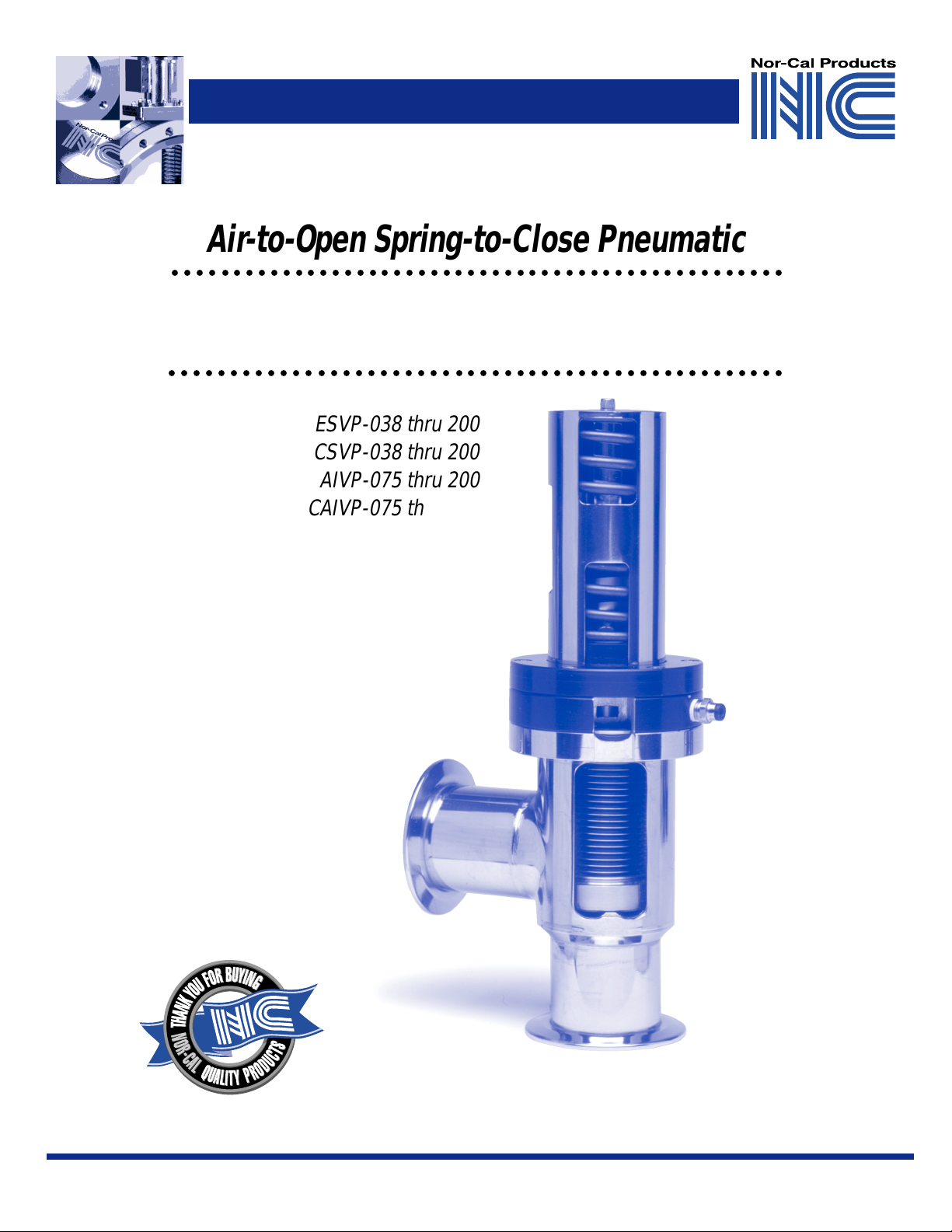
Air -to-Open Spring-to-Close Pneumatic
○○○○○○○○○○○○○○○○○○○○○○○○○○○○○○○○○○○○○○○○○○○○○○○○○○
Angle Valves
○○○○○○○○○○○○○○○○○○○○○○○○○○○○○○○○○○○○○○○○○○○○○○○○○○
ESVP-038 thru 200
CSVP-038 thru 200
AIVP-075 thru 200
CAIVP-075 thru 200
ILVP-038 thru 200
CILVP-038 thru 200
ESVP-038T thru 200T
CSVP-038T thru 200T
STVP-075
CSTVP-075
1
Nor-Cal Products, Inc. • 1967 S. Oregon St., Yreka, CA 96097 • 800-824-4166 or 530-842-4457 • FAX 530-842-9130 • ncsales@n-c.com • Web: www.n-c.com
Page 2
OPERATOR'S MA N U AL
© Nor-Cal Products, Inc., POPV-LIT 6/08
Air -to-Open Spring-to-Close Pneumatic Angle Valves
Unpacking
Inspect the shipping box before unpacking. Any damage
should be reported to the transportation company upon
receipt. Remove the valve from the box. Visually inspect the
valve, making sure that the flange faces are in good
condition. Apply 40-80 psig at the 1/8 inch NPT tapped hole
located on the black center plate of the valve to make sure the
valve operates smoothly before installation.
Installation Instructions
Determine that the valve and adjacent plumbing in the
vacuum system will be adequately supported when
installed. Make sure that the mating flanges are inline,
parallel and the correct distance apart to minimize straining
of the valve body. Remove the flange covers and wipe the
flanges and the gasket with a lint free wipe. With O-ring seal
flanges, apply a light film of vacuum grease to the O-ring
prior to installing in the flange groove. Proceed with the
installation while making sure that no foreign particles
enter the valve. Where applicable, lightly grease the flange
bolts with a high temperature anti-seize compound.
Carefully tighten around the flange in a 180º alternating
pattern until the flanges are in contact and the bolts are snug.
Valves will work equally well in any orientation. In addition,
vacuum can be on either side of the poppet and still maintain
a vacuum tight seal. However , it is recommended that valves
are installed with the poppet facing the process to prevent
contaminating the valve internals.
CAUTION: The air actuator sold under this agreement is spring
loaded. Any unauthorized disassembly of the air cylinder assembly will void the warranty, and any improper disassembly and maintenance is potentially dangerous. Do not dismantle the valve until
you shut off the air supply to the air solenoid and disconnect the
air supply line that is connected to the valve’s center plate (4).
Refer to the illustration and recommended service intervals
sections before installing a repair kit. Please contact Nor-Cal
to check on the warranty status prior to proceeding.
Viton® and Kalrez® are registered trademarks of DuPont Dow Elastomers.
®
Lubriplate
is a registered tracemark of Fiske Brothers Refining Company.
Operating Instructions
To ensure trouble free use, keep the valve clean and free
from contaminants. The air supply pressure should not exceed 80 psig. The bakeout temperature of the valve should
not exceed that of the elastomer that is used in it. See table
below for maximum recommended bakeout temperatures.
Valve Position
Closed
Pneumatic
120ºC
220ºC
Manual
ºC
100
150ºC
Viton
Kalrez
®
O-rings
®
O-rings
Open
150
280
ºC
ºC
Pneumatic Hook-up
Air-to-open, spring-to-close, pneumatic valves are to be
used with 3-way air solenoid valves. The air solenoid can be
purchased separately as a kit with installation instructions
and hardware. As an option, Nor-Cal can provide a pneumatic valve with the appropriate air solenoid in various
voltages pre-installed. Or, the valve may be connected
by an air line to an air solenoid in a remote location. The
instructions below are for the hook-up of a valve with a
pre-installed air solenoid. If the valve is connected to a
remote air solenoid, simply connect the air line from the
OUT port of the air solenoid to the 1/8 inch NPT hole on the
black valve centerplate using an appropriate fitting.
1. Connect a 60-80 psig air supply to the IN port
of theair solenoid using Teflon tape on all fittings to
ensure a leak-tight connection. For continued trouble
free operation, it is recommended that an air filter and
lubricator be used in the air line system.
2. Check the air solenoid name plate to confirm its
electrical specifications. Attach the appropriate
power source to the air solenoid.
3. Energizing the air solenoid will cause the valve
to open, de-energizing the air solenoid will cause
the valve to close.
Recommended Service Intervals
Service intervals are based on the number of cycles (openclose-open) a valve can be safely operated under clean
conditions without any maintenance. Nor-Cal recommends
that these valves be inspected for wear, and O-rings and
bellows be replaced as necessary after 250,000 cycles.
Process induced contamination and bake-out temperatures above 150ºC may shorten service intervals significantly. After service is completed these valves can again be
operated for the specified number of cycles.
2
Nor-Cal Products, Inc. • 1967 S. Oregon St., Yreka, CA 96097 • 800-824-4166 or 530-842-4457 • FAX 530-842-9130 • ncsales@n-c.com • Web: www.n-c.com
Page 3

OPERATOR'S MA N U AL
© Nor-Cal Products, Inc., POPV-LIT 6/08
1
Repair Instructions
Tools Required
3
/8" to 1" • 7/16" open end wrench
• 7/16" Socket
• .050" ball driver
1 1/2" • 3/16" ball driver
• 9/16" socket
• 7/16" open end wrench
• .050" ball driver
2" • 5/32" ball driver
• 9/16" socket
• 7/16" open end wrench
• .050" ball driver
Procedure
Make sure that the valve internals that are
subject to vacuum remain clean. Use lint free wipes
as necessary and keep seals free of contaminants.
1. Shut off the air supply to the air solenoid.
2. Remove the air fitting at the center plate (4).
3. Remove the air cylinder (1), apply 30 to 40 lbs. of force
against the top of the air cylinder (1) to neutralize the
spring (9) while removing the bonnet screws (13).
4. Remove valve internals from the body (7) and inspect
body flange O-ring (15) and poppet O-ring (17) and
replace if necessary.
5. If the bellows assembly (16) requires replacement,
remove the jam nut (11) by first inserting a 7/16" open
end wrench in the stem shaft (5) to keep the bellows
assembly (16) from rotating while removing the
jam nut (11). Remove piston cup (12) and slide off
center plate (4). Remove set screw (6) and replace
the bellows assembly (16).
6. Replace all O-rings as necessary including the piston cup (12).
7. Apply a light film of high vacuum grease on the O-rings
prior to installing them.
8. Apply anti-seize or equivalent on set screw (6)
and on bonnet screws (13).
9. Apply Lubriplate® high temperature grease
#PTL0161-001 or equivalent on stem shaft (5).
10. Re-assemble the valve in the reverse order .
2*
3
4
5
6
7
8
9
10
11
12
13
14
15
16
Diagram Key
1. Air Cylinder
2. Stem O-Ring
3. Retaining Plate
4. Center Plate
5. Stem Shaft
6. Set Screw
7. Body
8. Air Filter
9. Air Cylinder Spring
10. Spring Retainer
11. Jam Nut
12. Piston Cup
13. Bonnet Screws
14. Air Cylinder O-Ring
15. Body Flange O-Ring
16. Bellows Assembly
17. Poppet O-Ring
17
* 2" ID valves are
assembled with
two Stem O-Rings.
Warranty
Products manufactured by Nor-Cal Products Inc. (hereinafter referred
to as “Nor-Cal”) are warrantied against defects in material and workmanship for a period of twelve (12) months from the date of shipment
from Nor-Cal to the buyer . Any modification of the product by the buyer
or their agent voids this warranty. Liability under this warranty is expressly limited to replacement or repair (at Nor-Cal’s option) of defective parts. Nor-Cal may at any time discharge its warranty as to any of
its products by refunding the purchase price and taking back the products. This warranty applies only to parts manufactured, and labor provided by Nor-Cal within the applicable warranty period and shall be
subject to the terms and conditions hereof.
Items such as O-rings, bearings, pins, bellows, etc., by their nature,
may not function for one year due to process induced contamination
and/or continual cycling; if such items fail to give reasonable service
for a reasonable period of time, as determined solely by Nor-Cal, they
will be repaired or replaced by Nor-Cal at its election.
All warranty replacement or repair of parts shall be limited to equipment malfunctions which, in the sole opinion of Nor-Cal, are due or
traceable to defects in original materials or workmanship. Malfunctions caused by abuse or neglect of the equipment are expressly not
covered by this warranty. Nor-Cal expressly disclaims responsibility
for any loss or damage caused by the use of its products other than in
accordance with proper operating and safety procedures. Reasonable
care must be taken by the user to avoid hazards. In-warranty repaired or
replaced parts are warrantied only for the remainder unexpired portion
of the original warranty period applicable to the parts which have been
repaired or replaced.
3
Nor-Cal Products, Inc. • 1967 S. Oregon St., Yreka, CA 96097 • 800-824-4166 or 530-842-4457 • FAX 530-842-9130 • ncsales@n-c.com • Web: www.n-c.com
Page 4

OPERATOR'S MA N U AL
© Nor-Cal Products, Inc., POPV-LIT 6/08
Repair Kits
Nom
ID
3
/8" VSB ESVP-075-95 O-Ring Kit
1
/2" VSB ESVP-075-95 O-Ring and Gasket Kit
3
/4" VSB ESVP-075-95 O-Ring Kit ESVP-075, ESVP-075T, ILVP-075,
1" VSB ESVP-075-95 O-Ring Kit ESVP-100, ESVP-100T, ILVP-100
1 1/2" VSB ESVP-150-95 O-Ring Kit ESVP-150, ESVP-150T, ILVP-150
2" VSB ESVP-200-95 O-Ring Kit ESVP-200, ESVP-200T, ILVP-200
Bonnet
Type
CSB CSVP-075-95 O-Ring and Gasket Kit
CSB CSVP-075-95 O-Ring and Gasket Kit
CSB CSVP-075-95 O-Ring and Gasket Kit
CSB CSTVP-075-95 O-Ring and Gasket Kit
CSB CSVP-075-95 O-Ring and Gasket Kit
CSB CSTVP-075-95 O-Ring & Gasket Kit
CSB CSVP-150-95 O-Ring and Gasket Kit
CSB CSTVP-150-95 O-Ring and Gasket Kit
CSB CSVP-200-95 O-Ring and Gasket Kit
Kit
Part No.
ESV-075-16K Bellows Assembly ESVP-038, ESVP-038T and ILVP-038
ESVP-075-99 Complete Rebuild Kit
CSV-075-16K Bellows Assembly CSVP-038, CSVP-038T and CILVP-038
CSVP-075-99 Complete Rebuild Kit
ESV-075-16K Bellows Assembly ESVP-050, ESVP-050T and ILVP-050
ESVP-075-99 Complete Rebuild Kit
CSV-075-16K Bellows Assembly CSVP-050, CSVP-050T, and CILVP-050
CSVP-075-99 Complete Rebuild Kit
ESV-075-16K Bellows Assembly AIVP-075, and STVP-075
ESVP-075-99 Complete Rebuild Kit
CSV-075-16K Bellows Assembly CSVP-075, CSVP-075T, and CILVP-075
CSVP-075-99 Complete Rebuild Kit
CSV-075-16K Bellows Assembly CSTVP-075
CSTVP-075-99 Complete Rebuild Kit
ESV-075-16K Bellows Assembly and AIVP-100
ESVP-075-99 Complete Rebuild Kit
CSV-075-16K Bellows Assembly CSVP-100, CSVP-100T and CILVP-100
CSVP-075-99 Complete Rebuild Kit
CSV-075-16K Bellows Assembly CSTVP-100
CSTVP-075-99 Complete Rebuild Kit
ESV-150-16K Bellows Assembly and AIVP-150
ESVP-150-99 Complete Rebuild Kit
CSV-150-16K Bellows Assembly CSVP-150, CSVP-150T and CILVP-150
CSVP-150-99 Complete Rebuild Kit
CSTVP-150-16K Bellows Assembly CSTVP-150
CSTVP-150-99 Complete Rebuild Kit
ESV-200-16K Bellows Assembly and AIVP-200
ESVP-200-99 Complete Rebuild Kit
CSVP-200-16K Bellows Assembly CSVP-200, CSVP-200T and CILVP-200
CSVP-200-99 Complete Rebuild Kit
For Valve Model NumbersDescription
4
Nor-Cal Products, Inc. • 1967 S. Oregon St., Yreka, CA 96097 • 800-824-4166 or 530-842-4457 • FAX 530-842-9130 • ncsales@n-c.com • Web: www.n-c.com
 Loading...