

Page 1
Installation should be performed by a competent person
only. This product could be dangerous if incorrectly installed.
Check the pack to ensure all of the components are included.
When you are ready to start, make sure that you have all of
the correct tools to hand, have plenty of space, and that the
area for building is clean and dry.
Do not rush! Read these instructions first and run through
the sequence before you begin. Assembly should be
carried out in the steps shown in the following diagrams,
constructing one unit at a time and keeping fittings together
to avoid loss. Lay large panels on the floor using the
packaging for protection. Do not overtighten screws, as this
may damage the cabinet.
If any items are missing, or problems arise with fitting,
please call the Manufacturers’ Helpline on 01769 575500.
To clean - use mild soap and water only.
Do not use abrasive cleaners.
***
IMPORTANT INFORMATION
***
BEFORE YOU START
12
39
6
Turn to 2 o’clock to lock.
12
39
6
12
2
39
6
IMPORTANT: CAM FITTING AND LOCKING:
Press in firmly.
A
12
39
6
Leave no gaps.
12
39
6
12
39
6
Turn clockwise.
A
12
39
6
12
39
6
12
39
6
12
2
39
6
Fully insert .
B
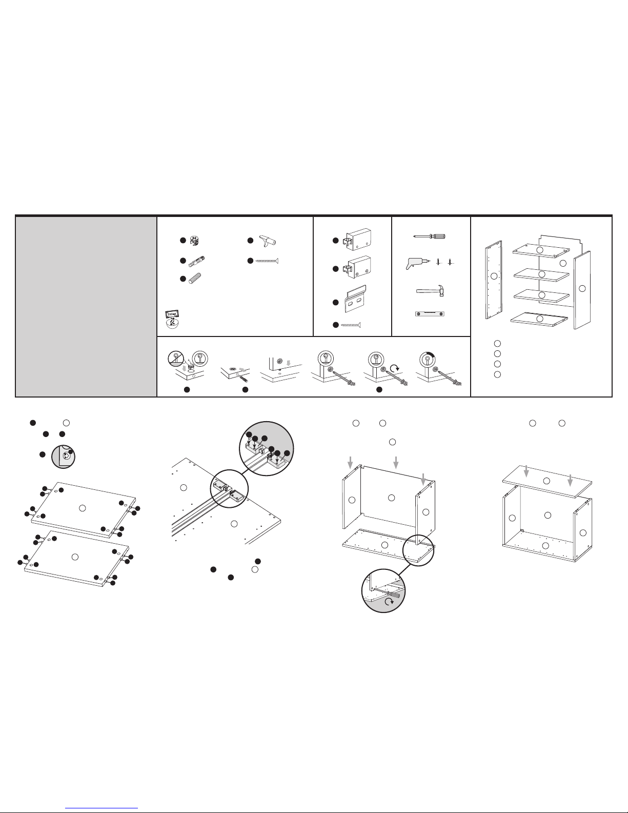
Fit the other panel to panels and tighten cams.Fit panels to panel . Tighten the cams as you go
(refer to cam fitting and locking section above).
Then carefully slide panel into the grooves.
Attach the LH wall hanging bracket and RH wall
hanging bracket to both panels , in the pre-marked
positions, using screws .
Insert into panels as shown.
Then insert and into panels as shown.
A
A
A
A
B
C
B
B
B
C
C
C
A
A
A
A
B
C
B
B
B
C
C
C
Please use scissors to open the bag of fittings and then empty
the contents into a bowl, so that they do not get lost!
2 x End Panel
2 x Top & Base Panel
2 x Shelf
1 x Back Panel
A
B C
A
B
C
F
J
M
N
P
8 x
8 x
8 x
2 x
8 x
1 x
1 x
2 x
HARDWARE: WALL FIXINGS: PANELS:
CROSS HEAD SCREWDRIVER
HAMMER
SPIRIT LEVEL
MINIMUM TOOLS REQUIRED:
DRILL & DRILL BITS (3mm & 5mm)
3 5
STEP 1: STEP 2: STEP 3:
ASSEMBLY GUIDE CSS 1610 07/15SINGLE WIDTH WALL CABINETS
15mm
15mm
15mm
15mm
15mm
25mm
30mm
15mm
15mm
25mm
30mm
50mm
E
4 x
15mm
15mm
25mm
A
IMPORTANT:
When fitting
Arrow points to
outside edge.
M
N
E
E
E
E
E
M
N
1
2
2
1
1
1
2
1
1
2
2 2
2
2
2
2
1
1 1
1
1
4
4
4
2
2
3
3
3
4
4
A
Page 2
ASSEMBLY GUIDE CSS 1610 07/15SINGLE WIDTH WALL CABINETS
JOINING & LEVELLING
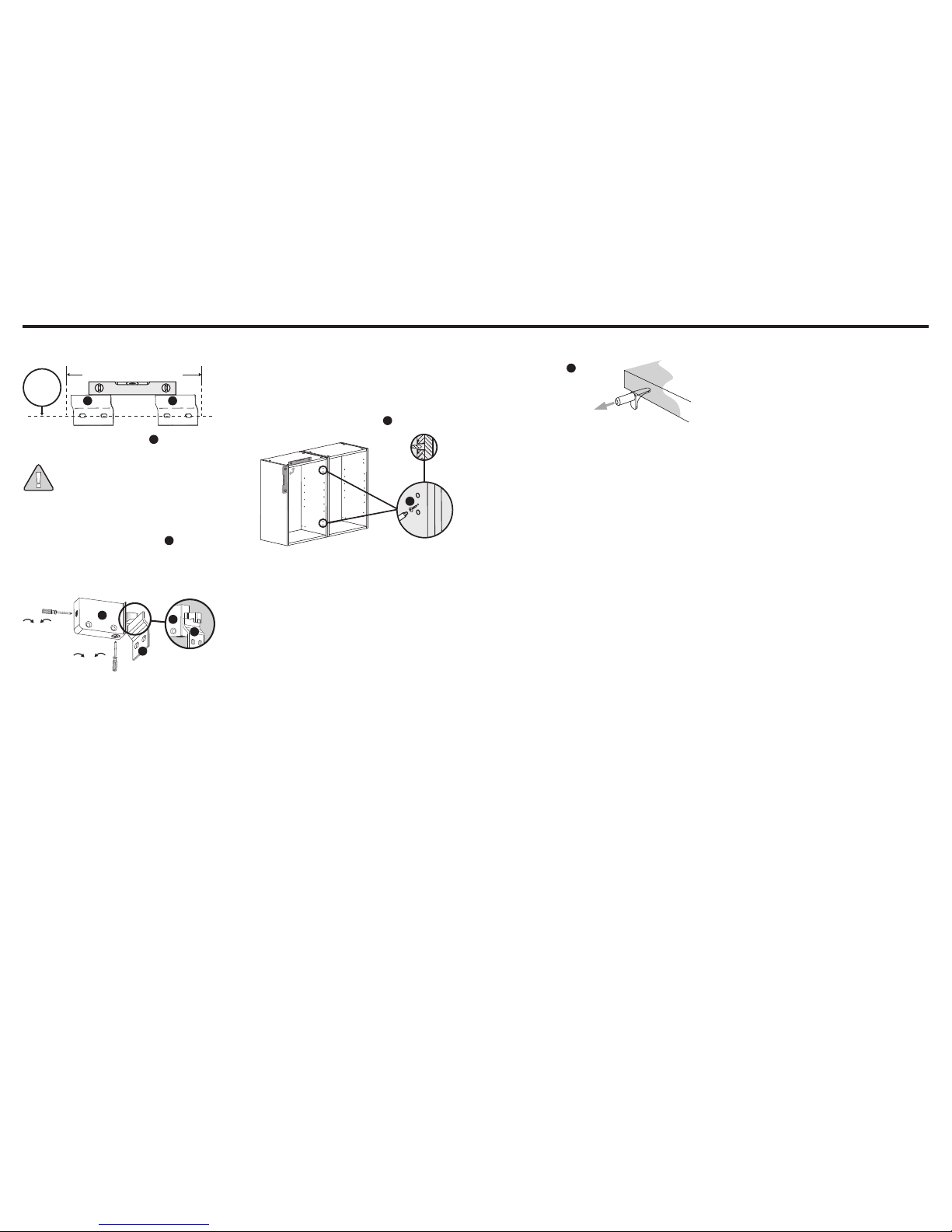
Mark 20mm on a 3mm dia. drill bit with masking
tape. Drill between the 2 holes drilled for the hinges,
through one cabinet side into the next, stopping when
you reach the marker.
Join the cabinets together with 2 x screws.
F
Push shelf support into
chosen shelf position holes,
4 per shelf.
Tilt and slide in shelf.
SHELF FITTING NOTES:
J
3mm
90°
F
FIXING TO WALL
Position and secure fitting brackets to the wall with
suitable fixings.
P
Spacing between side panels
allow 20mm clearance each side
Measure
62mm from
top of unit
PP
WARNING: There is a danger of this cabinet
falling off the wall if incorrectly fitted.
(Fixings are not supplied with the pack as they vary
according to the type of walls you have. If you are
unsure, ask an expert).
Hang the cabinet onto the wall brackets , ensuring
that the hooks are fully engaged behind the brackets,
as shown. (Pulling the fitted cabinet towards yourself,
whilst supporting its weight, will confirm this has
been achieved).
UP & DOWN
IN & OUT to Wall
P
M
Ensure the front face of the unit is vertical by using a
spirit level.
P
P
M
 Loading...