

Page 1

OPERATOR’S MANUAL
TRUCHECK™ 2 & TRUCHECK™ 2 PLUS
Part Number 34460 | Issue 1 | Original Instructions (English)
Page 2

Page 3

1
CONTENTS
Part Numbers Covered by This Manual 2
Set Up Instructions 2
Operating Instructions – TruCheck™ 2 Plus 3
Measurement Screen 3
Units Menu 4
Click Menu 4
Target Menu 4
Version Screen 5
Set Up Menu 5
Zero Resetting 5
Active From Setting 5
Target Indication 6
Using the Instrument 7
USB Port 7
Operating Instructions – TruCheck™ 2 Basic 8
Measurement Screen 8
Using the Instrument 8
Version Screen 8
Set Up Menu 9
Track Mode 9
Zero Resetting 9
Calibrate Mode 9
USB Port 9
Specifications 10
Calibration 12
Repair 12
Cleaning 12
Warning 12
Disposal 12
Page 4

2
Part
Number
Model
43524
TruCheck™ 2 Basic 350 N·m
43525
TruCheck™ 2 Plus 350 N·m
43530
TruCheck™ 2 Basic 1,100 N·m
43531
TruCheck™ 2 Plus 1,100 N·m
PART NUMBERS COVERED BY THIS MANUAL
This manual covers the set up and use of Norbar TruCheck™ 2 Basic and TruCheck™ 2 Plus instruments.
SET UP INSTRUCTIONS
1. Identify a suitable surface and position to mount the instrument.
2. Drill two mounting holes suitable for M10 fasteners (M10 Cap Screws of grade 12.9 minimum are
recommended).
3. Recommended fastener torque of 35 to 40 N·m (25 to 30 lbf·ft).
4. After connecting the provided power supply the instrument will be ready to use after approximately 12
seconds.
WARNING: ENSURE THE MOUNTING SURFACE IS CAPABLE OF SUPPORTING THE
INSTRUMENT WHEN THE RATED CAPACITY TORQUE IS APPLIED.
ONLY USE THE POWER SUPPLY PROVIDED.
DO NOT APPLY TORQUE ABOVE THE RATED CAPACITY.
TruCheck™ 2 is intended for testing torque tools only.
Page 5
3
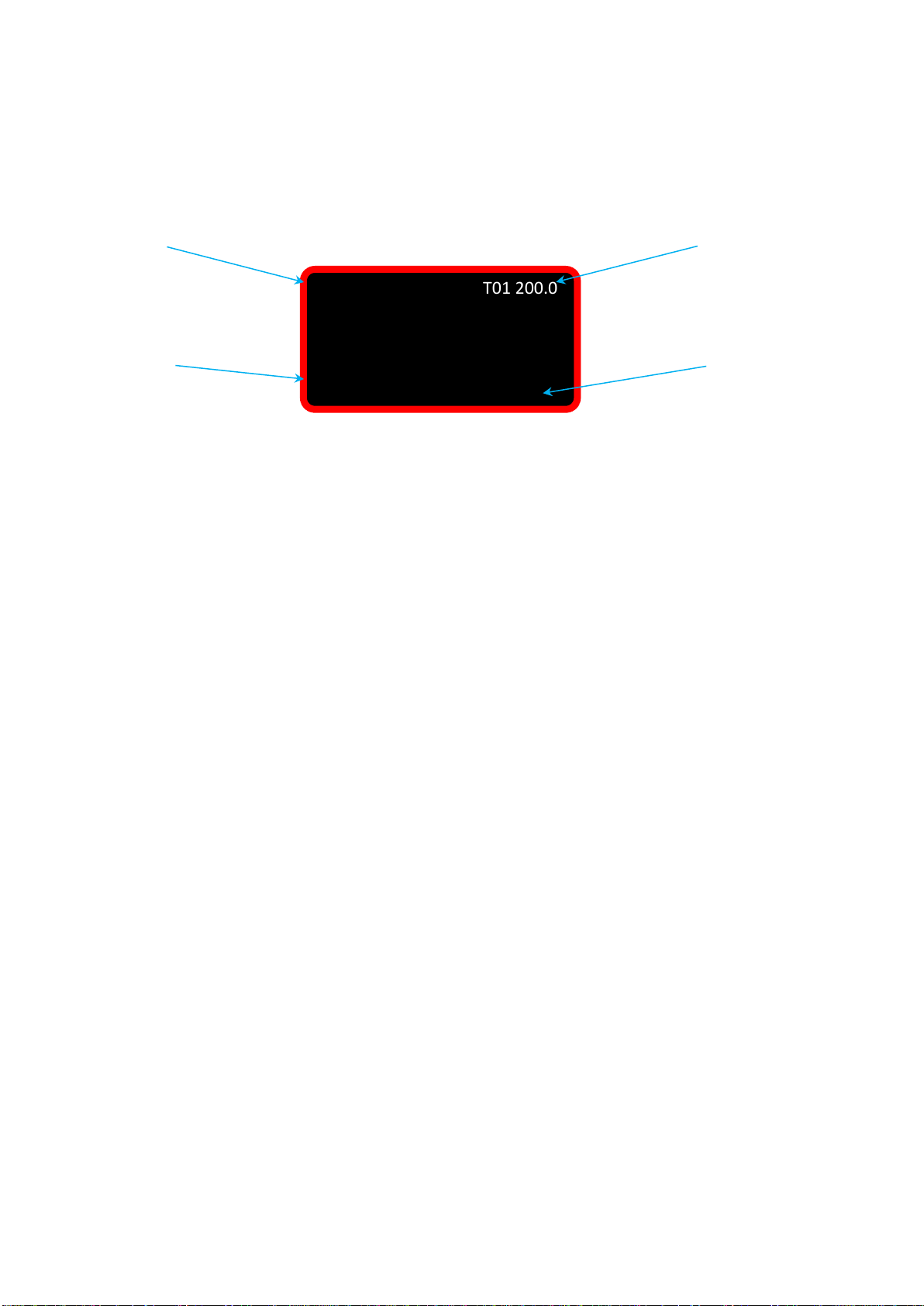
Track T01 200.0
Mode of Operation
Selected Target
Units of Measurement
Target Indicator Line
0.0
N·m
| | | | |
Changes the Units of
Measurement
(N·m, lbf·ft and lbf·in etc.)
To enable/disable units, use the
UNITS MENU (Press and Hold)
Changes the Selected Target
(T01 XXX.X, T02 XXX.X etc.)
Units are automatically changed to the
targets units.
NOTE: T-- ---- means Targets are OFF
To edit targets, use the TARGET MENU
(Press and Hold)
Changes the Mode of Operation
(Track, Click and Dial)
To change Click Mode settings, use
the CLICK MENU (Press and Hold)
Resets a captured peak
In Dial Mode (and Click Mode if set to
Manual Reset)
Zeroes the reading
In Track Mode if reading <4% Full Scale
Deflection (FSD)
In Click and Dial Mode if reading <1% FSD
OPERATING INSTRUCTIONS – TRUCHECK™ 2 PLUS
(43525 & 43531)
Measurement Screen
Page 6
4
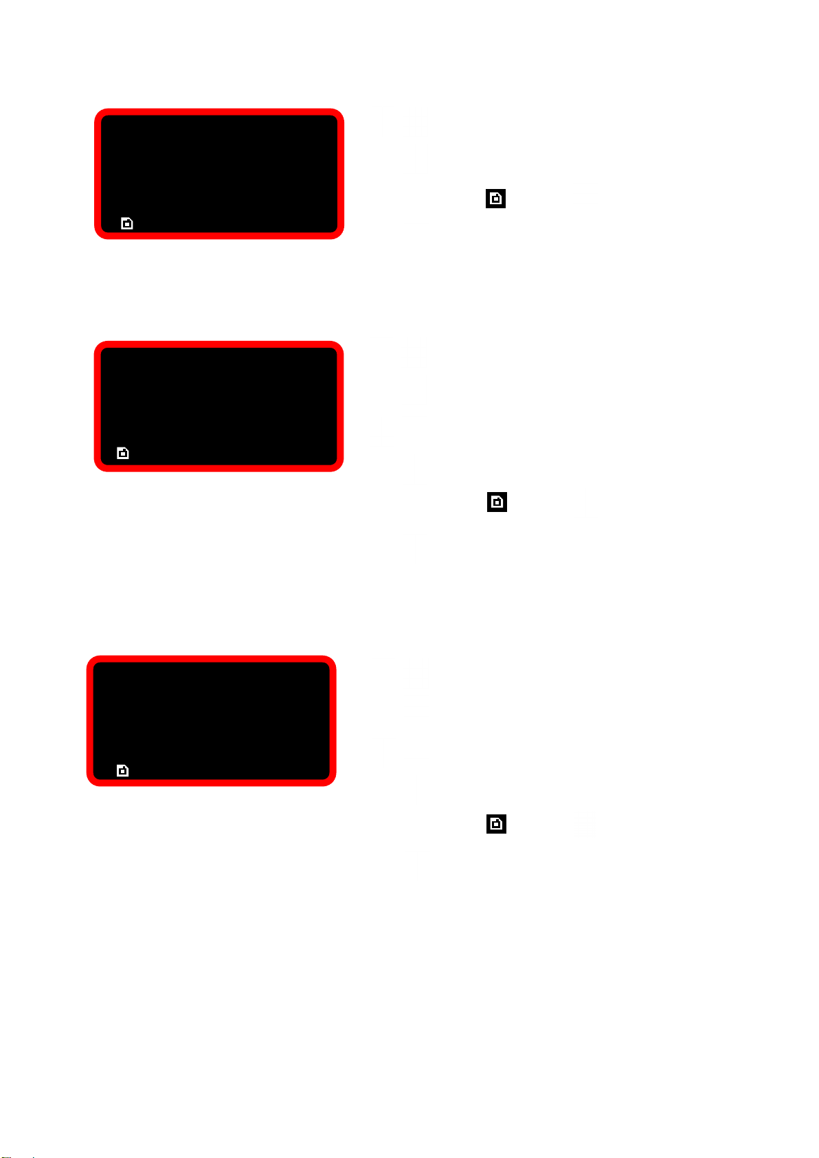
Select units to enable/disable
Toggle enable/disable (✓or )
Select and press to save and exit
Cancel (exit without saving changes)
Click Menu
Sensitivity High
Reset Auto
Hold Time 3 s
Select menu item (e.g. Sensitivity)
Confirm item
Change setting (e.g. High to Medium)
Confirm setting
Select and press to save and exit
Cancel (exit without saving changes)
Target Menu
# 01
Units N·m
Value 200.0
±% 03
Select menu item (e.g. Units)
Confirm item
Change setting (e.g. N·m to lbf·ft)
Confirm setting
Select and press to save and exit
Cancel (exit without saving changes)
• When changing the target value, you can press
and hold the buttons to speed up the change
• When you change the target units, the target
value will change to suit
• Setting the target value to ‘0’ disables it, meaning
it won’t be selectable in the measure screen
Units Menu
N·m ✓ lbf·ft ✓
dN·m lbf·in ✓
cN·m ft·lb
kgf·m in·lb
kgf·cm ozf·in
gf·m in·oz
Units Menu
NOTE: Units which can be enabled are TruCheck™ 2 Plus model specific (See Technical
Specification).
Click Menu
Setting Options
Sensitivity: High / Medium / Low
Reset: Auto / Manual
Hold Time: 1 sec / 2 sec / 3 sec
Target Menu
Setting Options
# (Target No.): 01 – 15
Units: N·m / lbf·ft / etc
Value: 0 or 2 - 100% Capacity
(e.g. 7.0 – 350.0)
±% (Tolerance): 1 – 15%
Page 7
5
Version
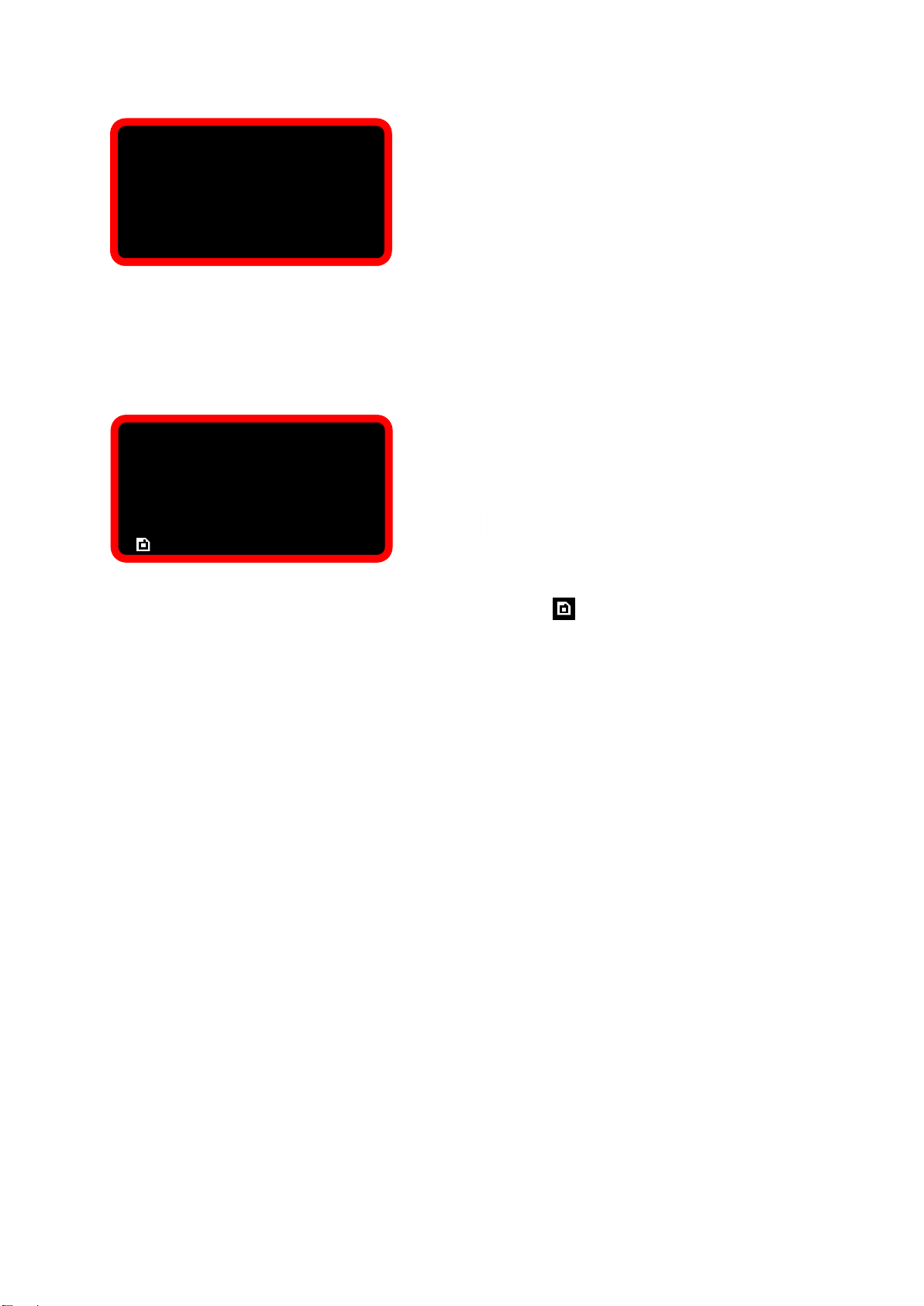
Press and hold from the measurement screen
to view the version screen
The version screen contains:
P/N (Part Number of the TruCheck™2 Plus)
S/N (Serial Number)
S/W (Software Version Number)
Press to return to the measurement screen
or
Press to enter the set up menu
Set Up Menu
Select menu item (e.g. Language)
Confirm item
Change setting (e.g. en to fr)
Confirm setting
Select and press to save and exit
Cancel (exit without saving changes)
Version Screen
P/N 43525
S/N 124356
S/W 1.0.1
Set Up Menu
Language en
LCD Contrast 160
LCD Invert ✓
Zero
Beep ✓
Active From 2.0%
Setting Options
Language: en / fr / de / it / da / es / fi /
sv / no / pt
LCD Contrast: 1 – 255 (Default 160)
LCD Invert: Invert (✓) or non-invert ()
Zero: Reset the stored Zero value
Beep: Enable (✓) or disable ()
Active From: 2.0 to 40.0 % (default 2.0%)
Zero Resetting
Zero resetting should only be performed if the TruCheck™ 2 Plus won’t zero in Track mode. If this is the
case the transducer may have been overstrained.
If the reading is unstable the TruCheck™ 2 Plus should be returned to a supplier approved agent for repair. It
is recommended to get the TruCheck™ 2 Plus recalibrated as soon as possible after resetting the zero.
Make sure no torque is being applied to the TruCheck™ 2 Plus and remove any tools from the input drive
when resetting the zero.
Active From Setting
This is the percentage of capacity at which Click mode and Dial mode will start to capture peak values.
Page 8
6
Click T01 200.0
190.7
| | | | |
Clockwise
Low
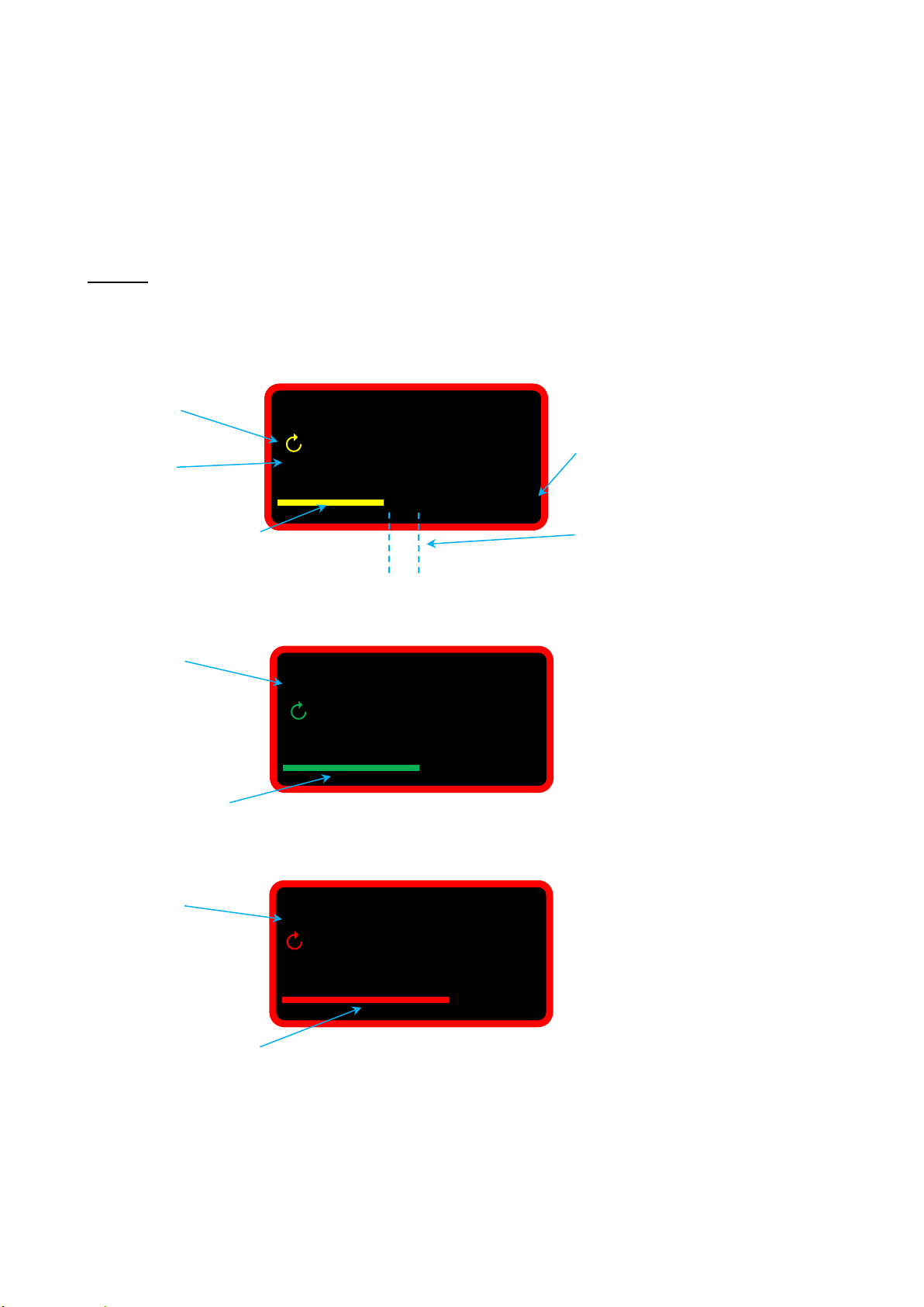
The target indicator line is
scaled to show ±20%
centred on the target value
(200 N·m)
The 2 lines closest to the
centre line indicate the
targets tolerance band (±3%)
Below tolerance band
N·m
Click T01 200.0
✓
202.1
Pass
In tolerance band
| | | | |
N·m
Click T01 200.0
212.4
| | | | |
N·m
High
Above tolerance band
Target Indication
When a target is selected, the TruCheck™ 2 Plus will indicate whether a reading is Low, Pass or High in
three different ways.
1. Text colour (Low = Yellow, Pass = Green, High = Red)
2. Target icons (Low = , Pass = ✓, High = )
3. Target indicator line
Example
Target 1 (T01) Set to 200.0 N·m ±3% (194.0 – 206.0 N·m)
Mode set to Click
First Reading 190.7 N·m (LOW)
Second Reading 202.1 N·m (PASS)
Third Reading 212.4 N·m (HIGH)
Page 9

7
Using the Instrument
1. Select mode of operation
2. Select target
3. Select units
4. Place torque screwdriver / torque wrench in the input drive and operate in the desired direction
5. Remove the torque screwdriver / torque wrench and zero the display (if required) by pressing the RESET
button
6. Place the torque screwdriver / torque wrench in the input drive and operate in the desired direction
USB Port
The USB port provides the power for the TruCheck™ 2 Plus. The supplied USB lead can also be used to
connect the TruCheck™ 2 Plus to a PC for communication of torque readings.
Connect the TruCheck™ 2 Plus to the PC and a virtual com port will appear in device manager. This com port
should be selected and configured to suit the program being used to display the torque readings.
Torque readings will be sent to the PC whenever the RESET button is pressed in any mode and when a peak
value is reset (either manually using the RESET button in Dial or Click mode or when auto-reset triggers in
Click mode).
If the PC doesn’t detect the TruCheck™ 2 Plus correctly (e.g. if running Windows 7 rather than Windows 10)
download the USB driver from the Norbar website.
The USB port can also be used to update the TruCheck™ 2 Plus software.
For the USB driver and to update the TruCheck™ 2 software visit:
https://www.norbar.com/Downloads/Software-Download/Trucheck2
Page 10

8
0.0
N·m
Version
P/N 43524
S/N 124365
S/W 1.0.1
Press and hold the ZERO button from the
measurement screen to view the version screen
The version screen contains:
P/N (Part Number of the TruCheck™2)
S/N (Serial Number)
S/W (Software Version Number)
Press the ZERO button to return to the
measurement screen
Or
Press and hold the ZERO button for 5 seconds to
enter the set up menu
OPERATING INSTRUCTIONS – TRUCHECK™ 2 BASIC
(43524 & 43530)
Measurement Screen
Using the Instrument
1. Place torque screwdriver / torque wrench in the input drive and operate in the desired direction
2. Remove the torque screwdriver / torque wrench and zero the display (if required) by pressing the ZERO
button
3. Place the torque screwdriver / torque wrench in the input drive and operate in the desired direction
Version Screen
Page 11

9
Press the ZERO button to select the menu item
Press and hold the ZERO button to confirm/toggle
the menu item
Setup Menu
Set Up Menu
LCD Invert ✓
Beep ✓
Track
Zero
Calibrate
X
Setting Options
LCD Invert: Invert (✓) or non-invert ()
Beep: Enable (✓) or disable ()
Track: Put the TruCheck™ 2 into Track mode
Zero: Reset the stored Zero value
Calibrate: Put the TruCheck™ 2 into Calibrate mode
X: Exit without saving changes
Save changes and exit
Track Mode
Pressing and holding the ZERO button on ‘Track’ will put the TruCheck™ 2 into Track mode. The
TruCheck™ 2 will remain in Track mode until it is disabled in the set up menu, or is power cycled.
The TruCheck™ 2 will always power up in its default mode (Click mode).
Zero Resetting
Zero resetting should only be performed if the TruCheck™ 2 won’t zero. If this is the case the transducer
may have been overstrained.
If the reading is unstable the TruCheck™ 2 should be returned to a supplier approved agent for repair. It is
recommended to get the TruCheck™ 2 recalibrated as soon as possible after resetting the zero.
Make sure no torque is being applied to the TruCheck™ 2 and remove any tools from the input drive when
resetting the zero.
Calibrate Mode
Only to be used by a supplier approved agent.
USB Port
The USB port provides the power for the TruCheck™ 2.
The USB port can also be used to update the TruCheck™ 2 software.
For the USB driver (if required) and to update the TruCheck™ 2 software visit:
https://www.norbar.com/Downloads/Software-Download/Trucheck2
Page 12
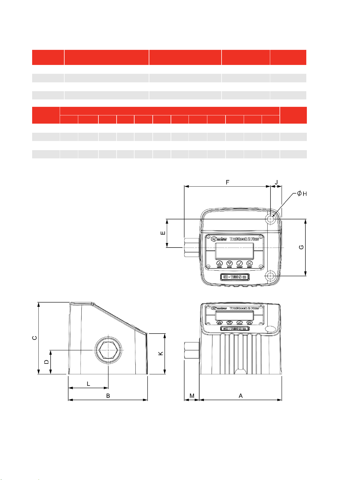
10
Part
Number
Model
Inbuilt Transducer
Connector
Capacity
Max
Torque
43524
TruCheck™ 2 Basic 350 N·m
½” Female Square Drive
10 - 350 N·m
525 N·m
43525
TruCheck™ 2 Plus 350 N·m
½” Female Square Drive
10 - 350 N·m
525 N·m
43530
TruCheck™ 2 Basic 1,100 N·m
27 mm Male Hex Drive
50 - 1,100 N·m
1,650 N·m
43531
TruCheck™ 2 Plus 1,100 N·m
27 mm Male Hex Drive
50 - 1,100 N·m
1,650 N·m
Part
Number
Dimensions (mm)
Weight
(kg)
A B C D E F G
ØH J K L M
43524
138
117
110
40
40
119
80
10.5
18.5
57.5
59
N/A
2.6
43525
138
117
110
40
40
119
80
10.5
18.5
57.5
59
N/A
2.6
43530
138
132.5
120
40
47.5
144
95
10.5
19
68
67
25
3.5
43531
138
132.5
120
40
47.5
144
95
10.5
19
68
67
25
3.5
SPECIFICATIONS
Page 13

11
N·m
dN·m
cN·m
kgf·m
kgf·cm
gf·m
lbf·ft
lbf·in
ft·lb
in·lb
ozf·in
in·oz
43525
350 N·m
✓
✓ ✓
✓ ✓ ✓ ✓
✓
43531
1,100 N·m
✓
✓
✓ ✓ ✓
✓
Display: 128 x 64 pixel RGB backlit LCD
Display update rate: 5 readings per second (5Hz)
Resolution: 4 digits
Zero suppression: None
Accuracy: See calibration certificate (Nominally ±1% of reading)
Units of measurement: Available units dependant on specific TruCheck™ 2 Plus model
Auto reset hold time: 3 seconds (Plus models – 1, 2 or 3 seconds)
AC power adapter: 90 to 264 Volts AC at 47 – 63 Hz input (World)
Interchangeable mains connectors included
Energy Efficiency Level VI
5V, 1,000 mA DC USB A output connector
Power consumption: 0.5 W – maximum
Operating temperature range: 0°C to +50°C
Storage temperature range: -20°C to +70°C
Maximum operating humidity: 85% relative humidity at 30°C
Environment: IP 40. Indoor use within a light industrial environment
Maximum working torsion: 120% of rated capacity
Absolute maximum torsion: 150% of rated capacity
Case materials / finish: Powder coated aluminium housing. Stainless steel transducer shaft
Electromagnetic Compatibility: Designed to comply with EN 61326-1.
Low Voltage Directive Designed to comply with EN 61010-1.
TRANSIENT OVERVOLTAGES up to the levels of OVERVOLTAGE
CATEGORY II
NOTE: Due to continuous improvement all specifications are subject to change without prior
notice.
Page 14

12
CALIBRATION
Your instrument has been supplied with a certificate of calibration. To maintain the specified accuracy it is
recommended that the instrument is recalibrated at least once per year. Recalibration should be carried out
by the supplier or by a supplier approved agent, where all the facilities to ensure the instrument is functioning
at maximum accuracy are available.
IMPORTANT: DO NOT REMOVE FRONT PANEL AS THERE ARE NO CALIBRATION SETTINGS
INSIDE.
REPAIR
Repair should be carried out by the supplier or by a supplier approved agent, where all the facilities to ensure
the instrument is functioning at maximum accuracy are available.
There are no parts for user repair inside the case.
CLEANING
Do not use abrasives or solvent based cleaners.
WARNING
If the instrument is used in a manner not specified by the manufacturer, the protection provided by the
equipment may be impaired.
DISPOSAL
This symbol on the product indicates that it must not be disposed of in the general waste.
Please dispose of according to your local recycling laws and regulations.
Page 15

OPERATOR’S MANUAL
TRUCHECK™ 2 & TRUCHECK™ 2 PLUS
Part Number 34460 | Issue 1 | Original Instructions (English)
NORBAR TORQUE TOOLS LTD
Wildmere Road, Banbury,
Oxfordshire, OX16 3JU
UNITED KINGDOM
Tel + 44 (0)1295 270333
Email [email protected]
NORBAR TORQUE TOOLS
45–47 Raglan Avenue, Edwardstown,
SA 5039
AUSTRALIA
Tel + 61 (0)8 8292 9777
Email [email protected]
NORBAR TORQUE TOOLS INC
36400 Biltmore Place, Willoughby,
Ohio, 44094
USA
Tel + 1 866 667 2279
Email [email protected]
NORBAR TORQUE TOOLS PTE LTD
194 Pandan Loop
#07-20 Pantech Business Hub
SINGAPORE 128383
Tel + 65 6841 1371
Email [email protected]
NORBAR TORQUE TOOLS (SHANGHAI) LTD
91 Building- 7F, No. 1122, Qinzhou North Road,
Xuhui District, Shanghai
CHINA 201103
Tel + 86 21 6145 0368
Email [email protected]
NORBAR TORQUE TOOLS INDIA PVT. LTD
Plot No A-168, Khairne Industrial Area,
Thane Belapur Road, Mahape,
Navi Mumbai – 400 709
INDIA
Tel + 91 22 2778 8480
Email [email protected]
www.norbar.com
© Norbar Torque Tools Ltd 2019
 Loading...