


WIRELESS CONNECT GATEWAY
Copyright Notice
Copyright © 2005-2015 Handlink Technologies Inc. All rights reserved. No part of this
document may be copied, reproduced, or transmitted by any means, for any purpose without
prior written permission. Protected by TW patent 223184, JPN patent 3099924 and China
patent ZL 03 2 04640.5.
Disclaimer
We shall not be liable for technical or editorial errors or omissions contained herein; nor for
incidental or consequential damages resulting from furnishing this material, or the performance
or use of this product. We reserve the right to change the product specification without notice.
Information in this document may change without notice.
Trademarks
Microsoft Win98, Windows 2000, WinXP, Win Vista and Win7 are registered trademarks of
Microsoft Corporation.
General: All other brand and product names mentioned herein may be registered trademarks of
their respective owners. Customers should ensure that their use of this produ ct does not
infringe upon any patent rights. Trademarks mentioned in this publication are used for
identification purposes only and are properties of their respective companies.

ACCESS GATEWAY
1
Table of Contents
Copyright Notice...................................................................................................................... ii
Disclaimer................................................................................................................................. ii
Trademarks ............................................................................................................................... ii
Chapter 1: Introduction .................................................................................................. 3
Package Contents...................................................................................................................... 3
Features..................................................................................................................................... 4
Precautions................................................................................................................................ 4
Outlook...................................................................................................................................... 5
Top Panel........................................................................................................................... 5
Rear Panel .............................................................. ........................................................... 6
Technical Specifications............................................. ........................................ ...................... 7
Hardware Specifications.................................................................................................... 7
Software Specifications...................................................................................................... 9
Chapter 2: Installation................................................................................................... 13
Connecting the Antennas........................................................................................................ 14
Installation Requirements ........................................ ............................................................... 14
Getting Started .......................... ..................................... ......................................................... 16
Chapter 3: Configuring the Wireless Connect Gateway............................................ 19
Setting Wizard......................................................................................................................... 19
Advanced Setup ...................................................................................................................... 46
AUTHENTICATION........................................................................................................ 48
RADIUS ........................................................................................................................... 51
BILLING .......................................................................................................................... 60
MANAGEMENT.............................................................. ..................................... ............ 93
SECURITY..................................................................................................................... 110
SYSTEM ......................................................................................................................... 118
System Status............................... ......................................................................... ................ 177
System ............................................................................................................................ 177
DHCP Clients................................................................................................................ 183
Session List ......................................... ..................................... ..................................... . 184
LAN Devices .................................... .......................................................................... .... 184
System Tools......................................................................................................................... 185
Configuration................................................................................................................. 186
Firmware Upgrade........................................................................................................ 187
Extended......................................................................................................................... 189

ACCESS GATEWAY
2
Boot Code....................................................................................................................... 190
System Account............................................... ................................................................ 190
SSL Certificate................................................................................................................ 197
Ping Command............................................................................................................... 198
Restart ............................................................................................................................ 198
Logout............................................................................................................................. 199
Chapter 4: Appendices................................................................................................. 201
Appendix A Signal Connection Arrangements ........................................................... .......... 201
RJ-45 Ethernet Port ....................................................................................................... 201
Appendix B Regulations/EMI Compliance........................................................................... 201
FCC Regulatory Statement............................................................................................. 201
Nomadix Wireless Connect Gateway.................................................................................... 202

ACCESS GATEWAY
1
Introduction 3
Introduction
The Wireless Connect Gateway is a compact intelligent gateway . It provides Plug’ Play Internet
access, advanced security and network management.
The Wireless Connect Gateway is designed for service providers, system integrators with or
without backend-RADIUS-Server to have integrated solution for rapid deployment, which can
start hotspot service quickly and easily and enhance service performance.
The Wireless Connect Gateway is an ideal solution for hotel lobbies, coffee bars, airport
lounges, conference facilities and other sites that commonly accommodate small groups of
visitors, and offer instant high-speed Internet connections. It is IP Plug and Play technology, it
accepts any client configuration, when client opens a browser the Wireless Connect Gateway
immediately recognizes new end-user and redirects their browser to customized Web pages.
There’s no need for end-us er to change any of their default network (Static IP), e-mail (SMTP
Server behind firewall), or browser settings (HTTP Proxy) or load any special software to
access the hotspot service. It’s completely Plug and Play with any browser.
Package Contents
Please inspect your package. The following items should be included:
◎
Nomadix Wireless Connect Gateway
Three antennas
One AC Power Adapter for Wireless Connect Gateway
Euro connector
Two screws for wall-mount
One UTP Ethernet/Fast Ethernet cable (Cat.5 Twisted-pair)
Optional Product:
◎
Nomadix VP 20 Printer
One AC Power Adapter for mini account generator printer
Euro connector
One UTP Ethernet/Fast Ethernet cable (Cat.5 Twisted-pair)
One Account Generator Printer User’s Guide

ACCESS GATEWAY
4 Introduction
If any of the above items are damaged or missing, please contact your dealer immediately.
Features
Wireless data rates up to 300 Mbps
Supports 200 Simultaneous wired and wireless users
IP Plug and Play (PnP)
Comprehensive security
WPA encryption
WPA2 Encryption
IP/URL filtering
Intelligent Management
Built-in AAA (Authentication/Accounting/Authorization) and Billing mechanism
Note: The "PnP" Function only can be used with a TCP/IP-based Network.
Precautions
Never remove or open the cover. You may suffer serious injury if you touch these
parts.
Never install the system in the wet locations.
Use only the original fitting AC power adapter otherwise there is a danger of severe
electrical shock.
Avoid exposing the Wireless Connect Gateway to direct sunlight or another heat
source.
Choose a well-ventilated area to position your Wireless Connect Gateway.

ACCESS GATEWAY
Introduction 5
Outlook
Figure 1 Nomadix Wireless Connect Gateway
Top Panel
The top panel of the Wireless Connect Gateway is shown below.
Figure 2 Wireless Connect Gateway Top Panel

ACCESS GATEWAY
6 Introduction
LEDs Indication
Rear Panel
The rear panel of the Wireless Connect Gateway is shown below.
LED State Description
Power Off The Wireless Connect Gateway is not receiving
electrical power.
Green The Wireless Connect Gateway is receiving electrical
power.
System Off The Wireless Connect Gateway status is defective.
Green The Wireless Connect Gateway status is complete.
Green
(Blinking)
During firmware upgrades, this system LED will blink.
WAN Off Port has not established any network connection.
Green A port has established a valid 10/100Mbps network
connection.
Green
(Blinking)
10/100Mbps traffic is traversing the port.
Eth1~4 Off Port has not established any network connection.
Green A port has established a valid 10/100Mbps network
connection.
Green
(Blinking)
10/100Mbps traffic is traversing the port.
WLAN Off The Wireless is not ready.
Green The Wireless Connect Gateway has established a valid
wireless connection.
Green
(Blinking)
The Wireless connection is active.

ACCESS GATEWAY
Introduction 7
Figure 3 Wireless Connect Gateway Rear Panel
1. ETH (1-4):
The rear panel supports four auto-sensing RJ-45 ports and all ports can be auto-switched
to MDI-II connections. The LAN ports are used for linking hosts or other network
devices.
2. WAN: One Ethernet port used for linking to an ISP connection.
3. Reset Button:
The Wireless Connect Gateway has a reset button at the rear panel of the device. Use this
control button to reset the system back to factory defaults.
4. Power Jack: Used to connect the external power supply with the Wireless Connect
Gateway.
Technical Specifications
Hardware Specifications
Network Specification
IEEE802.3 10BaseT Ethernet
IEEE802.3u 100BaseTX Fast Ethernet
IEEE802.11b/g/n Wireless LAN
ANSI/IEEE 802.3 NWay auto-negotiation
Wi-Fi Compatible
Connectors
Four LAN Ports (10BaseT/100BaseTX Auto cross-over)
One WAN Port (10BaseT/100BaseTX Auto cross-over)

ACCESS GATEWAY
8 Introduction
Encryption
WPA (Wi-Fi Protected Access)
WPA2 (Wi-Fi Protected Access)
External Antenna Type
2dBi (Max) Dual detachable diversity antenna with reverse SMA
LED Indicators
One POWER LED
One WAN 10/100M Link/Activity LED
Four LAN 10M/100M Link/Activity LEDs
One Wireless Link/Activity LED
One System LED
Power Requirement
External Power Adapter
Input: 100-240 VAC, 50/60 Hz
Output: 12V, 1.5A
Environment Conditions
Operating Temperature: 0 to 50°C
Storage Temperature: -10 to 60°C
Operating Humidity: 10~80% non-condensing
Storage Humidity: 10% to 90% non-condensing
Certifications
FCC part 15 Class B, CE ,
Dimension
Size: 223 (L) x 143 (W) x 36 (H) mm
Weight: About 500g (Net)

ACCESS GATEWAY
Introduction 9
Mounting
Desktop, Wal l Moun ted
Software Specifications
Networking
IEEE802.3 10BaseT Ethernet
IEEE802.3u 100BaseTX Fast Ethernet
IEEE802.11b Wireless LAN
IEEE802.11g Wireless LAN
IEEE802.11n Wireless LAN
Supports 200 Simultaneous Users
IP Plug and Play (iPnP)
HTTP Proxy Support
SMTP Server Redirection
DHCP Server
DHCP Relay
Static IP WAN Client
DHCP WAN Client
PPPoE WAN Client
PPTP WAN Client
NAT
NTP (Network Time Protocol) Support
DDNS
Marketing Cooperation
Advertisement URL link
Walled garden
Customizable log-on and log-off pages
Portal Page

ACCESS GATEWAY
10 Introduction
WISPr Smart Client
User Accounting and Authentication
Built-in Authentication
Web-based Authentication
RADIUS AAA Support (RFC 2865, 2866)
User Authentication and Accounting
Logout Window Timer Control
Security and Firewall
Layer 2 Isolation Security
SSL User Login page/ Configuration Page
SSL Administration
VPN Pass through (IPSec/PPTP)
Customize SSL Certificate
Pass Through IP/MAC/URL Address
Restricted Destination Filtering IP/URL
PPTP VPN Client
WPA
WPA2
Management
We b-based Managem ent Tool
Firmware Upgrade via HTTP/TFTP
Wizard setup for step-by-step Configuration
Backup/Restore/Factory Default Setting
Remote Authorized Management
Real-time Session List
LAN Device Management
Syslog (System/Connect/LAN device)

ACCESS GATEWAY
Introduction 11
E-mail logs
SNMP v1/v2 (MIB II)
System Information Table
Status Report (Daily/Monthly/System/Network)
SSL certificate upload
Extra Function with optional VP 20 Thermal Printer
Local Authentication
Local Accounting
Local Billing
Nomadix VP 20 Thermal Printer
Interface: Ethernet
Print Width: 48mm (Paper width: 58mm)
Paper Length: 50 M

ACCESS GATEWAY
12 Introduction

ACCESS GATEWAY
2
Installation 13
Installation
The followings are instructions for setting up the Wireless Connect Gateway. Refer to the
illustration and follow the simple steps below to quickly install your Wireless Connect
Gateway.
Wall-Mounting
The Wireless Connect Gateway can be mounted on a wall by applying the two mounting
brackets on screws.
Figure 4 Wall-Mounting Bracket - Bottom of Wireless Connect Gateway
Please refer to the following instructions for mounting a Wireless Connect Gateway on a wall
or other surface.
1. Install two screws on a wall according to the relative positions shown below.
Figure 5

ACCESS GATEWAY
14 Installation
2. Hang Wireless Connect Gateway on the wall by sliding the two screws in the mounting
brackets.
Note: If the screws are not properly anchored, the strain of the cables connected to the Wireless
Connect Gateway rear panel connectors could pull out the Wireless Connect Gateway from the
wall.
Connecting the Antennas
The Wireless Connect Gateway provides three antenna connectors on the rear of the
unit.
Figure 6 Antenna Connectors
Installation Requirements
Before installing the Wireless Connect Gateway, make sure your network meets the following
requirements.
System Requirements
The Wireless Connect Gateway requires one of the following types of software:
Windows 98 Second Edition/NT/2000/XP/Vista/7
Red Hat Linux 7.3 or later version
MAC OS X 10.2.4 or later version
Any TCP/IP-enabled systems like Mac OS and UNIX (TCP/IP protocol installed)
Web Browser Software (Microsoft I.E 5.0 or later version or Netscape Navigator 5.0
or later version)
One computer with an installed 10Mbps, 100Mbps or 10/100Mbps Ethernet card

ACCESS GATEWAY
Installation 15
UTP network Cable with a RJ-45 connection (Package contents)
Note: Prepar e twisted-pair cables with RJ-45 plugs. Use Cat.5 cable for all connections. Make sur e
each cable does not exceed 328 feet (Approximately 100 meters).
ISP Requirements
Verify whether your ISP uses fixed or dynamic IP. If it is a fixed IP, be sure to get the
IP from your ISP. For dynamic IP, which is mostly used, the PC will get the IP
automatically whenever it hooks to the modem.
Dynamic IP
Dynamic IP Setting
Fixed IP
Your fixed IP address for the Wireless Connect Gateway
Your subnet mask for the Wireless Connect Gateway
Your default gateway IP address
Your DNS IP address
PPPoE
Your user name from your ISP
Your password from your ISP
PPTP
PPTP Server IP Address from your ISP
PPTP Local IP address from your ISP.
PPTP Local IP subnet mask from your ISP.
Your user name from your ISP
Your password from your ISP
Your PC Requirements
The Static IP settings for the PC
Your PC’s fixed IP address
Your PC’s subnet mask

ACCESS GATEWAY
16 Installation
Your PC’s default gateway IP address
Your PC’s primary DNS IP address
Note: The gateway’s default IP address setting is “10.59.1.1”. The gateway’s default subnet mask
setting is “255.0.0.0”.
The Dynamic IP settings for the PC
We recommend that you leave your IP setting s as automatically assigned. By default, the
Wireless Connect Gateway is a DHCP server, and it will give your PC the necessary IP
settings.
Getting Started
1. Place the Wireless Connect Gateway and VP 20 Printer on a flat work surface.
2. Connect the Ethernet cable to the Wireless Connect Gateway’s Eth port.
3. Connect the other end of the Ethernet cable to the VP 20 Account Generator Printer’s
RJ45 port.
4. Ensure that your modem and computer are both switched on.
5. Use the supplied cable to connect the Wireless Connect Gateway's WAN port to the
modem. Check that the modem or router Status LED lights show a link present.
6. Connect your computer to one of the 10/100 Eth ports on the Wireless Connect Gateway.
Check that the Eth Port Status LED lights.
7. Configure the further parameters via a Web browser.

ACCESS GATEWAY
Installation 17
Figure 7 Wireless Connect Gateway Connection

ACCESS GATEWAY
18 Installation

ACCESS GATEWAY
3
Configuring the Wireless Connect Gateway 19
Configuring the Wireless
Connect Gateway
Setting Wizard
Step 1:
Start your browser, and then enter the factory default IP address 10.59.1.1 in your browser’s
location box. Press Enter.
Figure 8 Web Browser Location Field (Factory Default)
Step 2:
The Wireless Connect Gateway configuration tools menu will appear. In the Username and
Password field, type the factory default user name admin and password admin and click
Login. If you are first time setting the system, the device activate license page will appear.
Enter the activation license key, then the system will reboot. Type the default username and
password; the wizard setup screen will appear. You will be guided, step-by-step, through a
basic setup procedure.
Figure 9 Configuration Tools Menu
Username: admin
Password: admin

ACCESS GATEWAY
20 Configuring the Wireless Connect Gateway
Figure 10 Configuration Tools Menu
Figure 11 Activate Successful Screen
Figure 12 Activate Failed Screen
Enter the Activate License
key, total 32 characters.

ACCESS GATEWAY
Configuring the Wireless Connect Gateway 21
Figure 13 Wizard Setup Screen

ACCESS GATEWAY
22 Configuring the Wireless Connect Gateway
Figure 14 System Quick View
Notes:
This We b agent is best viewed with IE 5.0 or Netscape 6.0 and above browsers.
If you would like to change the password please see Step 10.
Username and Password can consist of up to 20 alphanumeric characters and are case
sensitive.
If for some reason your password is lost or you cannot gain access to the Wireless
Connect Gateway Configuration Program, please press the reset button to load the
device to manufacturer defaults.
If the Wireless Connect Gateway doesn’t send packet in 5 minutes (default), the
Wireless Connect Gateway will logout automatically.

ACCESS GATEWAY
Configuring the Wireless Connect Gateway 23
Proxy needs to set disable first when administrator accesses admin UI.
Step 3: Internet Connection Setting
Select the appropriate Internet connection type to connect to your ISP.
Figure 15 Internet Connection Setting Screen
DHCP Client
The device can work as a DHCP client. This allows the device to obtain the IP address and
other TCP/IP settings from your ISP. If your ISP supports this feature, please enable DHCP
Client.

ACCESS GATEWAY
24 Configuring the Wireless Connect Gateway
Figure 16 Internet Connection Setting Screen—DHCP Client Setting
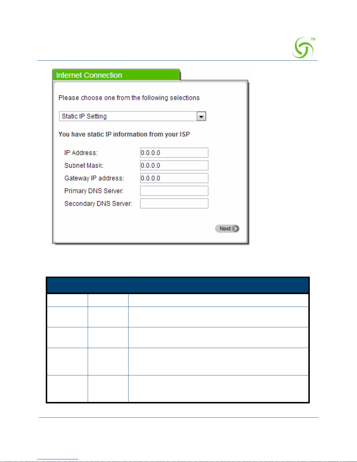
Static IP Setting
If Static IP Setting is selected, then this screen will appear. Enter the IP address
information provided by your ISP.
ACCESS GATEWAY
Configuring the Wireless Connect Gateway 25
Figure 17 Internet Connection Setting Screen—Static IP Setting
Item Default Description
IP Address 0.0.0.0 Enter the IP address provided by your ISP.
Subnet
Mask
0.0.0.0 Enter the subnet mask for the IP address.
Gateway IP
Address
0.0.0.0 Enter the Gateway IP Address provided by your ISP.
Primary
DNS
Server
Empty Enter the primary DNS server IP address provided by your
ISP.
Secondary
DNS
Server
Empty Enter the secondary DNS server IP address provided by your
ISP. If the primary DNS Server IP is not available, secondary
DNS Server IP would be used.

ACCESS GATEWAY
26 Configuring the Wireless Connect Gateway
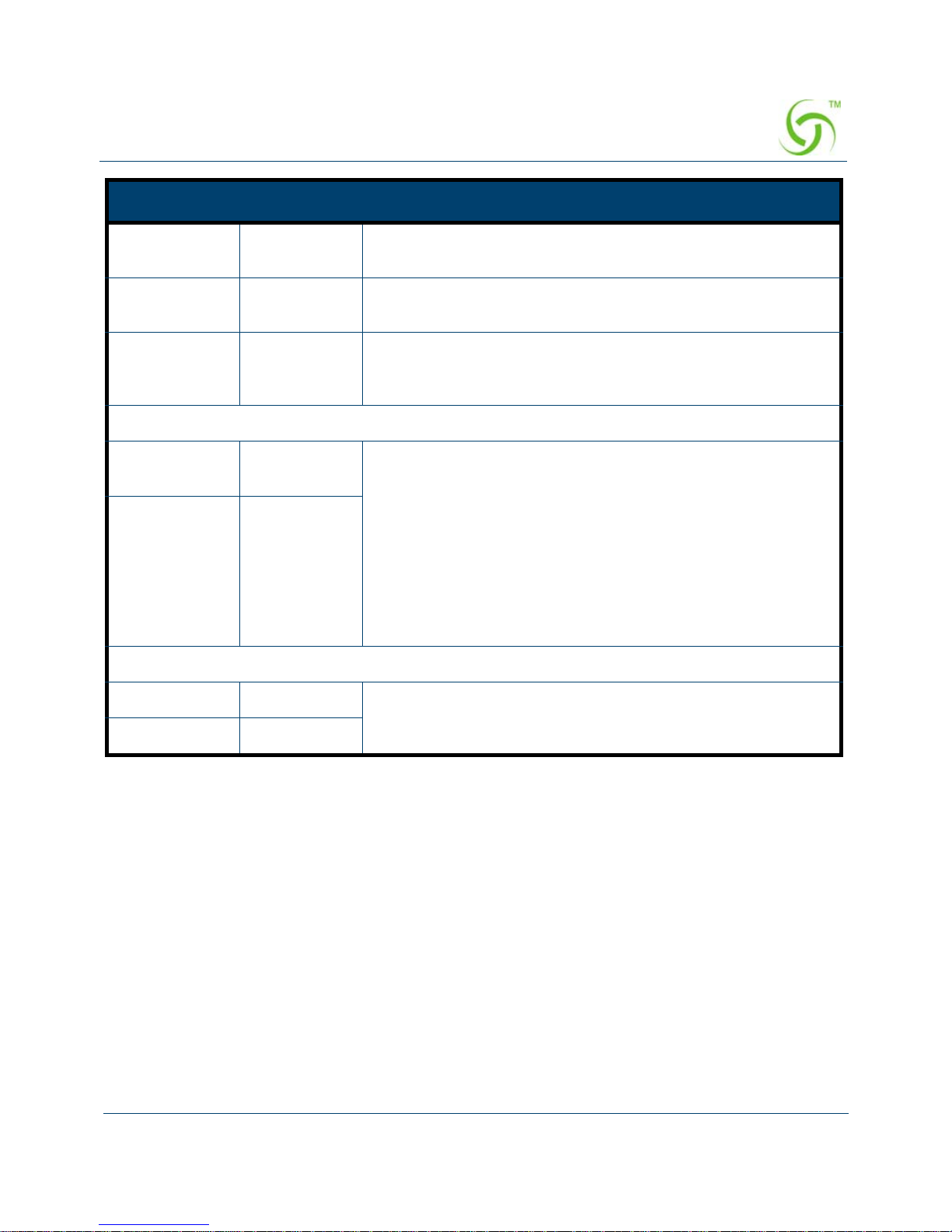
PPPoE (Point-to-Point Protocol over Ethernet)
If “ PPPoE ” is selected, then this screen will appear. Enter the username, password
and other major fields.
Figure 18 Internet Connection Setting Screen—PPPoE Setting
Item Default Description
Username Empty Enter the user name provided by your ISP. The user name
can consist of up to 80 alphanumeric characters and is case
sensitive.
Password Empty Enter the user password provided by your ISP. The password
can consist of up to 80 alphanumeric characters and is case
sensitive.
ACCESS GATEWAY
Configuring the Wireless Connect Gateway 27
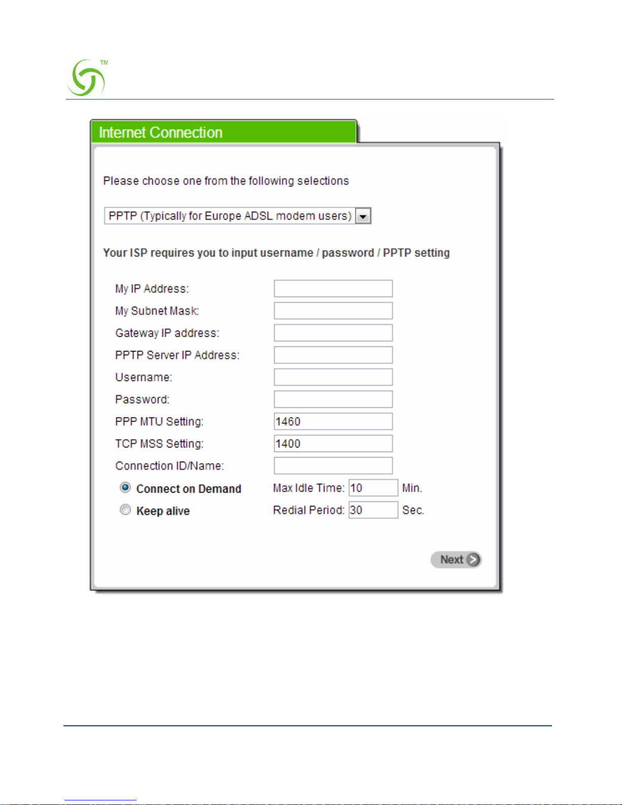
PPTP Client (Point-to-Point Tunneling Protocol)
If “PPTP” is selected, then this screen will appear. Fill out all the information
provided by your ISP.
PPP MTU
Setting
1492 MTU (Maximum Transfer Unit) specifies maximum
transmission unit size.
TCP MSS
Setting
1452 MSS (Maximum Segment Size) specifies maximum segment
size.
Service Name Empty Enter the service name provided by your ISP. The service
name can consist of up to 64 alphanumeric characters and is
case sensitive.
Connect on Demand and Max Idle Time
Connect on
Demand
Enable You can configure your Wireless Connect Gateway to
disconnect from your ISP after a specified period of time
(Max Idle Time). If you have been disconnected due to
inactivity, Connect on Demand enables your Wireless
Connect Gateway to automatically re-establish your
connection as soon as you attempt to access the Internet
again. If you wish to activate Connect on Demand, click the
radio button. If you want your Internet connection to remain,
click the radio button of keep alive. The Max Idle Time
maximum value is 65535 minutes.
Max Idle Time 10 Minutes
Keep alive and Redial Period
Keep alive Disable This option keeps your PPPoE enabled Internet access
connected indefinitely, even when it sits idle. The redial
period maximum value is 65535 seconds.
Redial Period 30 Seconds
Item Default Description
ACCESS GATEWAY
28 Configuring the Wireless Connect Gateway
Figure 19 Internet Connection Setting Screen—PPTP Client Setting

ACCESS GATEWAY
Configuring the Wireless Connect Gateway 29
Item Default Description
My IP Address Empty Enter the PPTP local IP address provided by your
ISP.
My Subnet Mask Empty Enter the PPTP local Subnet Mask address for the
IP address (My IP Address).
Item Default Description
Gateway IP
Address
Empty Enter the PPTP server Gateway IP address
provided by your ISP.
PPTP Server IP
Address
Empty Enter the PPTP server IP address provided by your
ISP.
Username Empty Enter the user name provided by your ISP. The user
name can consist of up to 80 alphanumeric
characters and is case sensitive.
Password Empty Enter the user password provided by your ISP. The
password can consist of up to 80 alphanumeric
characters and is case sensitive.
PPP MTU Setting 1460 MTU (Maximum Transfer Unit) specifies maximum
transmission unit size.
TCP MSS Setting 1400 MSS (Maximum Segment Size) specifies maximum
segment size.
Connection ID/
Name
Empty Enter the connection ID or connection name. The
connection ID/Name can consist of up to 81
alphanumeric characters and is case sensitive.
Connect on Demand and Max Idle Time

ACCESS GATEWAY
30 Configuring the Wireless Connect Gateway
Step 4: Wireless Setting
This page allows you to define the ESSID, Channel ID and WPA/WPA2 encryption for
wireless connection.
Figure 20 Wireless Setting Screen
Connect on
Demand
Enable You can configure your Wireless Connect Gateway
to disconnect from your ISP after a specified period
of time (Max Idle Time). If you have been
disconnected due to inactivity, Connect on Demand
enables your Wireless Connect Gateway to
automatically re-establish your connection as soon
as you attempt to access the Internet again. If you
wish to activate Connect on Demand, click the radio
button. If you want your Internet connection to
remain, click the radio button of keep alive. The Max
Idle Time maximum value is 65535 minutes.
Max Idle Time 10
Minutes
Keep alive and Redial Period
Keep alive Disable This option keeps your PPTP enabled Internet
access connected indefinitely, even when it sits idle.
The Redial Period maximum value is 65535
seconds.
Item Default Description

ACCESS GATEWAY
Configuring the Wireless Connect Gateway 31
Step 5: E-mail Server Setting
Wireless Connect Gateway allows an extra Email server parameter to forward the Connects Email.
Figure 21 E-mail Service Setting Screen
Item Default Description
Wireless
Connection
Enable Enable or Disable Wireless connection
Channel 6 Enter the channel ID for wireless connection.
Note: Channel 12~13 are not allowed to use in North
America area.
802.11 Mode 802.11n+802.11
g+802.11b802.11n
+802.11g+802.11b
802.11n+802.11g+
802.11b
Select the 802.11 mode of following::
-802.11n+802.11g+802.11b
-802.11n+802.11g
-802.11g+802.11n
-802.11n only
-802.11g only
-802.11b only

ACCESS GATEWAY
32 Configuring the Wireless Connect Gateway
Step 6: Authentication Service Setting
Figure 22 Authentication Service Setting Screen
Item Default Description
Email Server
Redirect
No Disables or enables email server redirect function.
Some subscribers Email server may be protect by
firewall or NAT network. Wireless Connect
Gateway provides an extra Email server parameter
to forward the subscribers Email. The Wireless
Connect Gateway not only forwards the
subscribers E-mail via configured server but also
changes the SMTP header. The recipient of your Email sees the message as if you sent it from your
local Internet Service Provider, not from your
present location.
Email Server’s IP
address or Domain
name
Empty Before configuring this, please make sure the E-
mail sever relay function is enabled on your server.
Enter the email server IP address or domain name.
The field must not exceed 50 characters.
SMTP Port 25 Enter the SMTP port. The SMTP port allowed
range is 25 or 2500 to 2599.

ACCESS GATEWAY
Configuring the Wireless Connect Gateway 33
Step 7: Billing Profile Setting
This function is used to setup a billing profile. A billing profile is a descriptio n of how you
want to charge your customer.
Item Default Description
Built-in
Authentication/ No
Authentication
No
No Authentication)
Yes ―
Wireless Connect Gateway provides Builtin Authentication for service provider to
build up an Internet service without any
extra authentication software. If Yes is
selected, service provider can generate
the subscriber account inside the Wireless
Connect Gateway, and the system will
authenticate the subscriber login
according to the generated account.
No―
Subscriber can get direct access to the
Internet without entering username and
password.

ACCESS GATEWAY
34 Configuring the Wireless Connect Gateway
Figure 23 Billing Profile Setting Screen
Item Default Description
Service Time to
Finish
Options: Time to Fi nish or Accumulation.
Time to Finish―
The Subscriber can access Internet only one time with one
account. Once the subscriber logs in, the pre-defined
usage time will start until it runs out even the subscriber
stops access the Internet before time runs out.
Accumulation―
The subscriber can access Internet many times with one
account. The system can keep and accumulate every
single usage time until the pre-defined usage time runs out.
Currency $ Enter the appropriate currency unit or currency symbol.

ACCESS GATEWAY
Configuring the Wireless Connect Gateway 35
Step 8: Account Generator Printer Setting
There are two different choices, one is exclusive printer (Nomadix VP 20 Printer), and the
other is non-exclusive printer. Exclusive printer is a portable thermal printer that is integrated
with Wireless Connect Gateway to press one button to generate accounts and receipt
immediately without PC operating. Non-exclusive printer can use the PC Web-based browser
to print out user accounts.
Number
of
decimals
places
2 Enter the billing decimal value. The field maximum value is
3.
No 01~03 The index number of billing profile. In Wizard setup, we
provide only 3 billing profiles.
Name 30
minutes/
1 hour/
2 hours
It is the name of billing profile. The maximum allowed
characters length is 12.
Usage
Time
30
minutes/
1 hour/
2 hours
The duration of the billing period. When this period expires,
user account will be discontinued.
Charge 1.00/2.00/
3.00
Enter the amount of Internet service. The amount
maximum value is 999999.
Item Default Description

ACCESS GATEWAY
36 Configuring the Wireless Connect Gateway
Figure 24 Printer Setting Screen
Figure 25 Nomadix VP 20 Printer
Button A
Button B
Button C

ACCESS GATEWAY
Configuring the Wireless Connect Gateway 37
Step 9: Accounting Setting
Three-buttons Printer Setting
Figure 26 Accounting Setting Screen (Three Button Printer)
Figure 27 Billing Profile Setting Screen

ACCESS GATEWAY
38 Configuring the Wireless Connect Gateway
Web-based Account Generator Setting
Figure 28 Web-based Account Generator Setting Screen
Item Default Description
Button A~ C 01 Define each button’s billing profile. Select one
billing profile by clicking it in the list box.
Printed Copies
Number of copies to print 1 This value is number of copies.
This function allows you to produce custom bill based on
your requirements.
Click “I want to setup the web-based accounting now if exclusive printer does not work”
open the “Web-based Account Generator Setting” screen to start the web-based
accounting function.

ACCESS GATEWAY
Configuring the Wireless Connect Gateway 39
Click on button to preview and operate account generator panel.
Figure 29 Account Generator Panel
Item
Default
Description
Billing Profile (Button
A~C)
Define each button’s billing profile. Select one billing profile by
clicking in the list box.
Printout
Number of copies to
print
1 Select the number of copies by clicking in the list
box.
- This function allows you to produce custom bill
based on your requirements.
Web-based Account
Username account Enter the user name for web-based account
generator. The user name can consist of up to 80
alphanumeric characters and is case sensitive.
Password account Enter the password for web-based account
generator. The password can consist of up to 80
alphanumeric characters and is case sensitive.
Confirm Empty Enter the password for confirmation.
Button A
Button B
Button C

ACCESS GATEWAY
40 Configuring the Wireless Connect Gateway
Click on button to create a new account.
Click “View Account List” to display current account information.
Figure 30 Account List
Click on refresh button to update the account list page
The field name button in this list show that this list can be sorted in ascending/descending order
according to the corresponding field name.
Select the check boxes and click ‘Delete’ to delete accounts.
Delete all accounts in account list.
Note: This page will refresh automa tica lly every 5 minutes.
Customize Printout Text
This function allows you to produce custom bill based on your requirements.

ACCESS GATEWAY
Configuring the Wireless Connect Gateway 41
Figure 31 Customize Printout Text Setting Screen
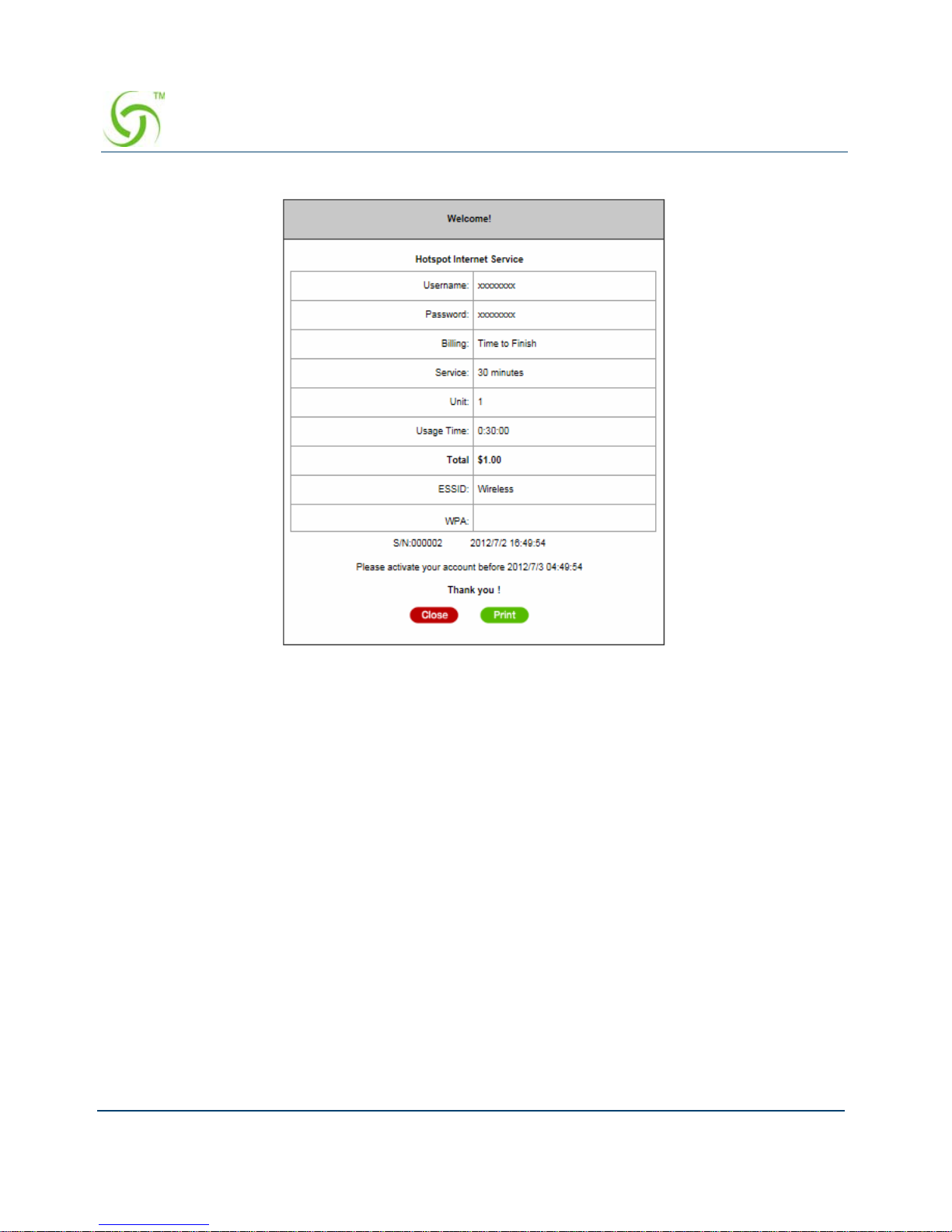
Click the button to displays the account on the screen as it would appear when printed.
ACCESS GATEWAY
42 Configuring the Wireless Connect Gateway
Figure 32 Example- PC-connected printer Printout (Time to Finish)

ACCESS GATEWAY
Configuring the Wireless Connect Gateway 43
Figure 33 Example- PC-connected printer Printout (Accumulation)

ACCESS GATEWAY
44 Configuring the Wireless Connect Gateway
Figure 34 Example- Account Generator Printer Printout (Time to Finish)
Figure 35 Example- Account Generator Printer Printout (Accumulation)

ACCESS GATEWAY
Configuring the Wireless Connect Gateway 45
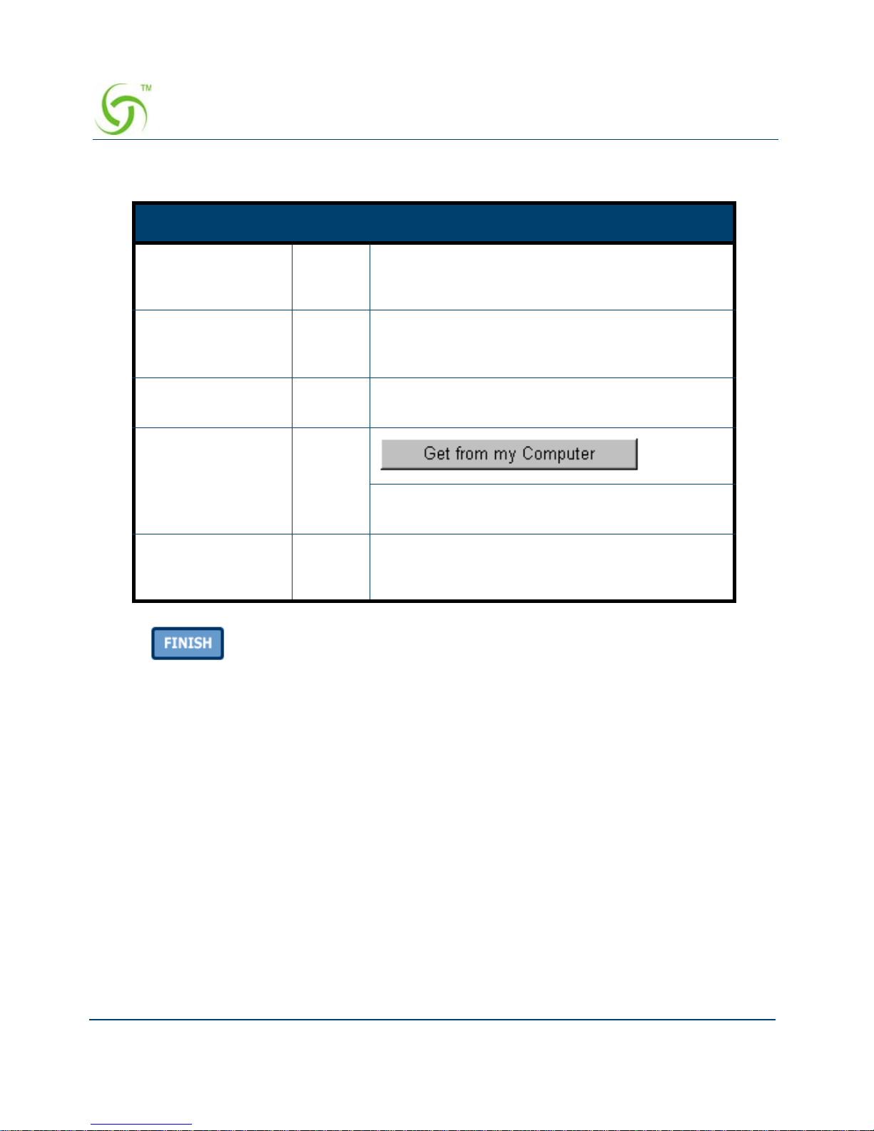
Step 10: System Setting
Figure 36 System Setting Screen
ACCESS GATEWAY
46 Configuring the Wireless Connect Gateway
Click the button to save the settings then the system will restart.
Advanced Setup
The Advanced Setting enables you to configure advanced settings related to accessing the
Internet, including,
Item Default Description
Username admin Enter the user name. The user name can consist
of up to 80 alphanumeric characters and is case
sensitive.
Password admin Enter the user password. The password can
consist of up to 80 alphanumeric characters and is
case sensitive.
Confirm Empty Enter the password of administrator for
confirmation.
System date and
time
YYYY/
MM/DD
HH:MM:
SS
Click Get from my Computer button to correct
the system date and time.
Secure
Administrator IP
Address
All This function allows remote user to management
the device. You can specify one or any IP
addresses for remote control the system.

ACCESS GATEWAY
Configuring the Wireless Connect Gateway 47
AUTHENTICATION
AUTHENTICATION
RADIUS
BILLING
BILLING
ACCOUNTING
CREADIT CARD
MANAGEMENT
LAN DEVICES
SYSLOG
SESSION TRACE
BANDWIDTH
SNMP
SECURITY
PASS THROUGHT
FILTERING
SHARE
SECURE REMOTE
SYSTEM
SYSTEM
WAN/LAN
SERVER
CUSTOMIZATION
PORTAL PAGE
ADVERTISEMENT
WALLED GARDEN
DDNS
WIRELESS
Figure 34
Advanced Setting
Item Screen
ACCESS GATEWAY
48 Configuring the Wireless Connect Gateway
ACCOUNT GENERATOR
Note: After changing the settings of device, please click apply button to save the new settings.
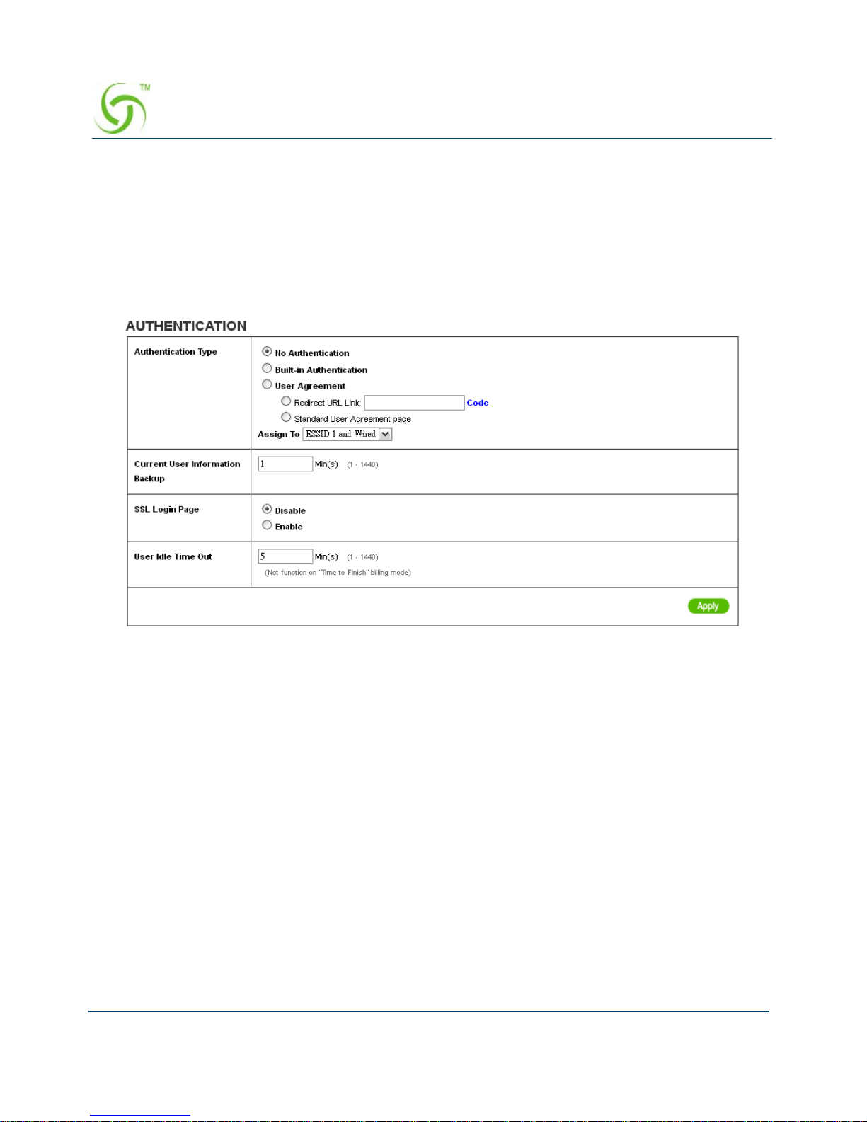
AUTHENTICATION
Authentication
Figure 38 Authentication Setting Screen

ACCESS GATEWAY
Configuring the Wireless Connect Gateway 49
Copy and paste the following HTML Code into your home page to produce user agreement
login page.
Item Default Description
Authentication
Type
No
Authentication
Option: No Authentication, Built-in Authentication or User
Agreement.
No Authentication―
Subscriber can have direct access to the Internet without
entering username and password.
Built-in Authentication―
Wireless Connect Gateway provides “Built-in
Authentication” for service provider to build an Internet
service without any extra authentication software. If
“Built-in Authentication” is selected, service provider can
generate the subscriber account inside Wireless
Connect Gateway and the system will authenticate the
subscriber login according to the generated account.
User Agreement―
Subscriber must accept the service usage agreement
before they can access the Internet.
Assign to ― ESSID 1 and
wired
Copy and paste the following HTML Code into your
home page to produce redirect subscriber login page.
The input format can be http://www.yahoo.com.
The maximum character of the URL Link is 200. Empty
Redirect Login Page URL The system provides
automatic backup of the account information and unused
account to flash ROM. This function allows the
administrator to adjust the backup time. The default
value is 1 minute. The current user Information backup
valid range is 1 to 1440. 1 Min(s) Current User
Information Backup Note: ESSID 1 and Wired
Maximum supports 1 Voucher.
The Wired Interface only works with ESSID 1
The wired interface default will be no authentication if
assign the Build-in or User Agreement to ESSID2~4.
ESSID 2
ESSID 3
ESSID 4
Administrator could define which ESSID need to support
Build-in Authentication or User Agreement.
If administrator choose to using No Authentication, and
Assign to combo list will be blank, without function.

ACCESS GATEWAY
50 Configuring the Wireless Connect Gateway
Figure 39 Preview Redirect Login Page Code
Click Apply button to save the new settings. Needs to be a Nomadix green
Item Default Description
SSL Login Page Disable Enables or disables SSL security of login page.
User Idle Time
Out
5 Minutes The user idle time out valid range is 1-1440.

ACCESS GATEWAY
Configuring the Wireless Connect Gateway 51
RADIUS
Figure 40 RADIUS Setting Screen

ACCESS GATEWAY
52 Configuring the Wireless Connect Gateway
Item Default Description
RADIUS
Authentication
Disable Option: No Authentication or RADIUS Server.
Disable (No Authentication) ―
Subscriber can have direct access the Internet
without enter username and password.
Enable (RADIUS Authentication) ―
Wireless Connect Gateway provides “RADIUS
Authentication” for service provider to build up an
Internet service with RADIUS server. If RADIUS
Authentication is enabled, all Subscribers’
authentication will be sent to the RADIUS Server by
RADIUS protocol (RFC 2865, 2866).
Time to Finish/
Accumulation
Enable Service provider provides two different accounting
calculations for the Internet service.
Primary RADIUS Server
Server IP Empty Enter the IP address of RADIUS server.
Authentication Port 1812 Enter the authentication port number; the
authentication port number must match with the
RADIUS server setting. The allowed numbers are
from 0 to 65535.
Accounting Port 1813 Enter the accounting port number; the accounting
port number must match with the RADIUS server
setting. The allowed numbers are from 0 to 65535.
Share Secret Key Empty The share secret key, the key number also has to
match with the Server setting. Up to 64 characters
are allowed.
Secondary RADIUS Server
Server IP Empty Enter the IP address of RADIUS server.
Authentication Port 1812 Enter the authentication port number; the
authentication port number must match with the
secondary RADIUS server setting. The allowed
numbers are from 0 to 65535.
Accounting Port 1813 Enter the accounting port number; the accounting
port number must match with the secondary RADIUS
server setting. The allowed numbers are from 0 to
65535.

ACCESS GATEWAY
Configuring the Wireless Connect Gateway 53
Access Code
Share Secret Key Empty The share secret key, the key number also has to
match with the secondary RADIUS Server setting. Up
to 64 characters are allowed.
Retry times when
Primary fail
1 Specify the retry times when primary fail.
Retry Frequency ~
Seconds
3 The field default value is 3 seconds.
Accounting Service Disable Enables or disables the accounting service.
Interim Update
Time
5 Minutes Specify the interim update time.
Authentication
Method
CHAP Enter the authentication method of RADIUS server.
WISPr Smart Client
Enable Disable Enables or disables WISPr Smart Client roaming
function.
Login Mode Directly Reply Options: Directly Reply, Proxy Reply with “Redirect
Login Page” URL and Proxy Reply with Specific URL.
The login mode information for the IPASS GIS
connection. (Provided by your ISP).
Item Default Description

ACCESS GATEWAY
54 Configuring the Wireless Connect Gateway
Click Apply button to save the new settings.
Access Code Login Page Configuration
The Wireless Connect Gateway provides Access code three different login page formats,
including standard, redirect, advanced and frame format.
Item Default Description
Access Code Disable Enable or Disable
support Access Code
Function.
Empty The access code can
consist of up to 30
alphanumeric
characters and is case
sensitive.
Valid Date/Time Never Expire The option let service
provider specify an
expiry time or never
expire for Internet
Service

ACCESS GATEWAY
Configuring the Wireless Connect Gateway 55
Standard
Figure 41 Access Code Standard Login Page Customization Setting Screen
For some service providers, they may hope to have a customized subscribers’ login page for
the users. This function helps them to realize the ideal page presentation. The page elements
include login page title, background color, subtitle etc.
Item Default Description
Logo Disable Select the check box to display service provider’s logo.
Title WelcomeEnter the title name of subscriber login page. The
maximum allowed characters length is 80.
Subtitle Hot Spot
Internet
Service
Enter the subtitle name of subscriber’s login page. The
maximum allowed characters length is 80.
Footnote Disable Allow the administrator to input the footnote such as
“Please contact to our Customer Service Center, EXT
141”. The maximum characters of the footnote is 240.

ACCESS GATEWAY
56 Configuring the Wireless Connect Gateway
Figure 42 ESSID 4 Login Page Screen
Redirect
This allow service provider to redirect the subscribers’ browser to a specified home
page.
Figure 43 Redirect Login Page Setting Screen
Copy and paste the following HTML Code into your home page to produce redirect subscriber
login page.
Copyright Enable The copyright is allowed the administrator to input a
paragraph in the subscriber’s login page for copyright
information. The maximum characters of the copyright
are 80.
Background
Color
FFFFFF The background text color can be specified color. For the
specified text color format please view the color grid. The
allowed format is Hexadecimal.
Item Default Description

ACCESS GATEWAY
Configuring the Wireless Connect Gateway 57
Figure 44 Redirect Login Page Code Screen

ACCESS GATEWAY
58 Configuring the Wireless Connect Gateway
Figure 45 Advanced Login Page Setting Screen
Advanced
Item Default Description
Welcome
Slogan
Welcome The maximum allowed characters length is 80.
Page
Background
None The page can be any specified color for the background
color format. Please view the color grid. The allowed format
is Hexadecimal.
Article Empty The article allows the administrator to input a paragraph in
the subscriber login page for advisement or announcement.
The maximum number of characters for the article is 1024.
Article Text
Color
000000 The article text color can be a specified color. For the
specified text color format please view the color grid. The
allowed format is Hexadecimal.
Article
Background
Color
None The article background can be a specified color. For the
background color format please view the color grid. The
allowed format is Hexadecimal.

ACCESS GATEWAY
Configuring the Wireless Connect Gateway 59
Figure 46 Color Gird
Frame
If “Frame” is selected the subscriber login page will be separate into top frame and bottom
frame. Bottom Frame is a default format for username and password input, Top Frame is
allowed to be a specified a URL link.
Information Empty Allows the administrator to input the text information such as
address, telephone number and fax information. The
maximum number of characters for the information is 80.
Comments Empty Allows the administrator to input the text comments such as
“Please contact to our Customer Service Center, EXT 141”.
The maximum number of characters of the comment is 80.
Item Default Description

ACCESS GATEWAY
60 Configuring the Wireless Connect Gateway
Figure 47 Frame Login Page Setting Screen
BILLING
Billing
The function is used to setup a billing profile. A billing profile is a description of how you want
to charge your customer.
Item Default Description
Top Frame URL
Link
Empty The input format can be http://www.yahoo.com. The
maximum characters for the URL Link are 200.
Bottom Frame - This frame will show the standard login page.
www.caesarpark.com

ACCESS GATEWAY
Configuring the Wireless Connect Gateway 61
Figure 48 Billing Setting Screen
Item Default Description
Enable Credit Card
Service
Disable Enables or disables the credit card service. Before
you enable credit card service, make sure that
your credit service is configured to work and the
currency is American dollars. You must convert all
prices on your billing page into American dollars
(U.S. dollars). For details, see section 3-2-8 Credit
Service.

ACCESS GATEWAY
62 Configuring the Wireless Connect Gateway
Figure 49 Credit Service Setting Screen
Figure 50 Error Dialog Box (Credit Card Service=Enable)

ACCESS GATEWAY
Configuring the Wireless Connect Gateway 63
Figure 51 Accumulation and Time to Finish
Item Default Description
Time to
Finish
Enable The subscriber can access the Internet only for a single
session. After the subscriber logs in, Internet access is
available until the session ends or time runs out, whichever
comes first.
Accumulation
Accumulation Disable The subscriber can access the Internet multiple times with
one account. The system accumulates the time of each
session until the purchased time limit is reached.
Idle Time Out 5 Min(s) The idle time out valid range is 1-1440. If the idle time out is
set as 5 minutes, it means if the account doesn’t send a
packet in 5 minutes, the account will logout automatically.
Item Default Description
Billing Profile
Currency $ Enter the appropriate currency unit or currency
symbol.
A
B
C
A
login
logo ut
logo ut
login
login
logo ut
login
finis
h
A
c cumulati on Time to Finish
Usage ti me= A +B+ C Usage time= A
Time Bar Time Bar
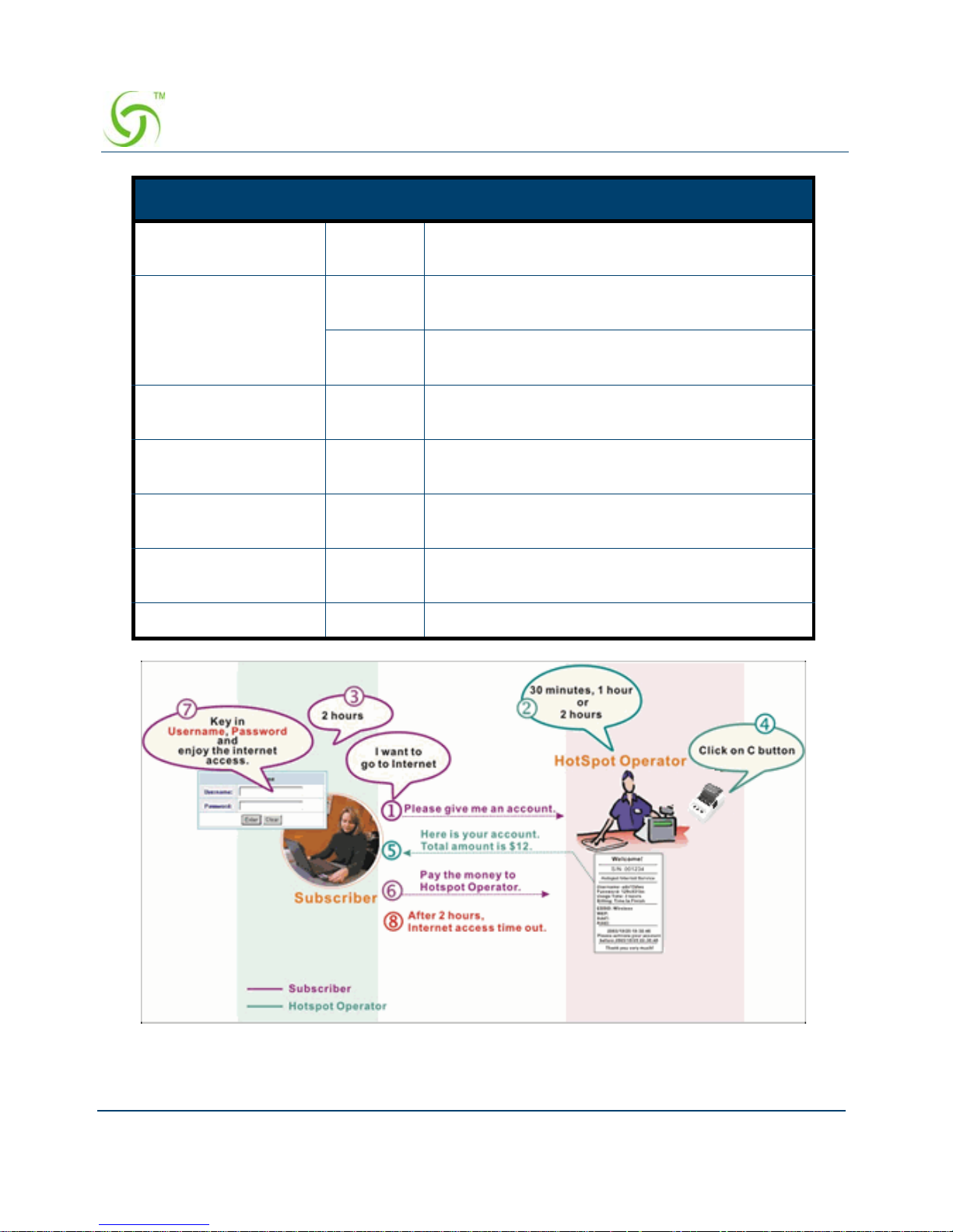
ACCESS GATEWAY
64 Configuring the Wireless Connect Gateway
Figure 52 Pre-paid Procedure Diagram
Number of decimals
places
2 Enter the number. The field maximum value is 3.
Tax Percentage Disable This check box is used to indicate the taxable
status of the account.
5% Enter the tax rate (i.e. a 5% sales tax is entered
as 5).
No. +1~+10 The index number of billing profile. In Advanced
setup, we provide 10 billing profiles.
Active - Click on check box, activate or deactivate the
billing profile.
Name - It is the name of billing profile. The maximum
allowed characters is 12.
Account Usage time - The duration of the billing period. When this
period expires, user account will be discontinued.
Charge - Enter the unit rate amount (i.e. $35.00)
Item Default Description

ACCESS GATEWAY
Configuring the Wireless Connect Gateway 65
Click Apply button to save the new settings.
Figure 53 Success Dialog Box
Accounting
This function allow service provider to generate the Connect accounts.

ACCESS GATEWAY
66 Configuring the Wireless Connect Gateway
Figure 54 Accounting Setting Screen

ACCESS GATEWAY
Configuring the Wireless Connect Gateway 67
Figure 55
Figure 56 Account Process Diagram
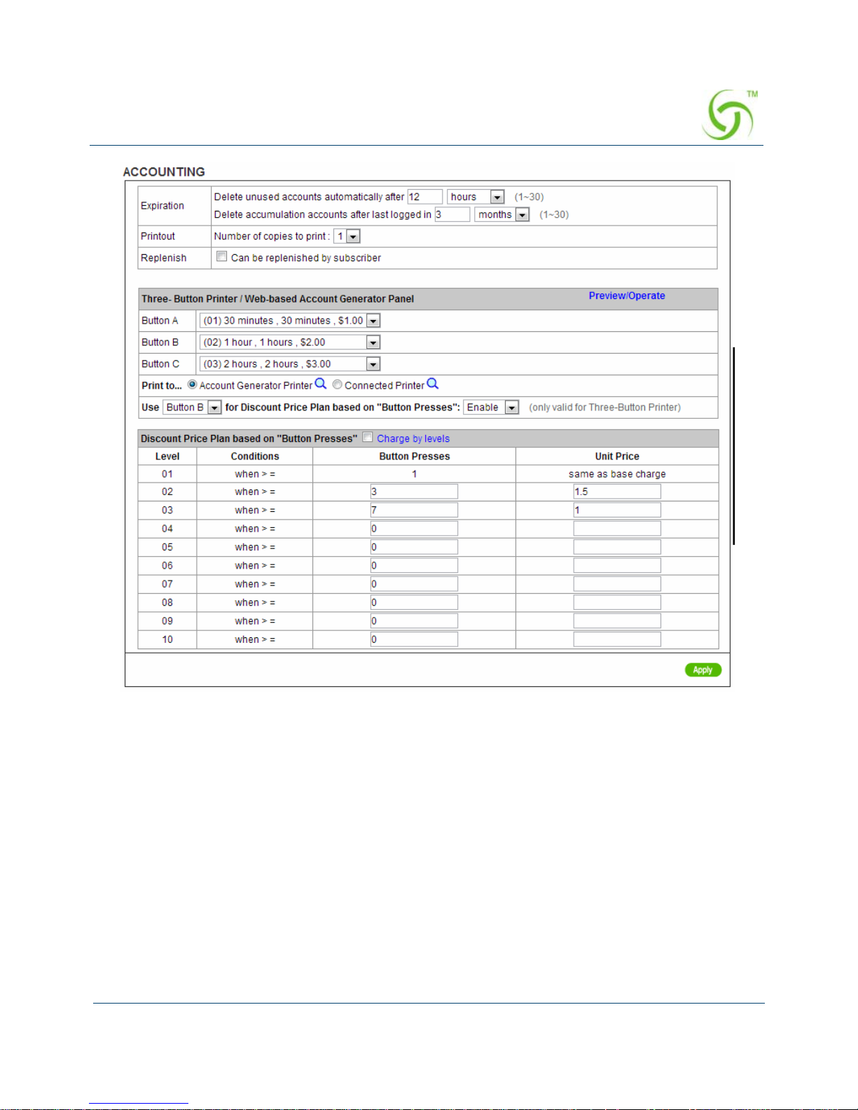
Item Default Description
Expiration
Delete unused
accounts
automatically after
~hours
automatically
24 hours Enter the number of hours/minutes/days. The field
maximum value is 30 hours/minutes/days.
Accumulation
account will be
deleted after last
logged in ~
3 months Enter the number and select time unit from list box.
The field maximum value is 30 month/ days/ hours.
Printout
Number of copies to
print
1 The system allows you to print all of your bills. Select
a number of copies by clicking in the list box.
Can be replenished
by subscriber
Click the check box to enable the replenish function.
ACCESS GATEWAY
68 Configuring the Wireless Connect Gateway
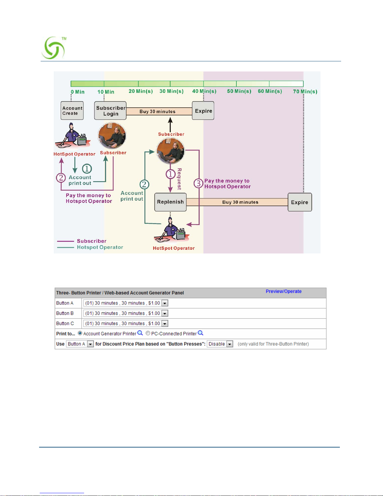
Can be replenished by subscriber=Enable
Three-Button Printer/ Web-based Account Generator Panel
Figure 57 Three-Button Printer/ Web-based Account Generator Panel Setting Screen
ACCESS GATEWAY
Configuring the Wireless Connect Gateway 69
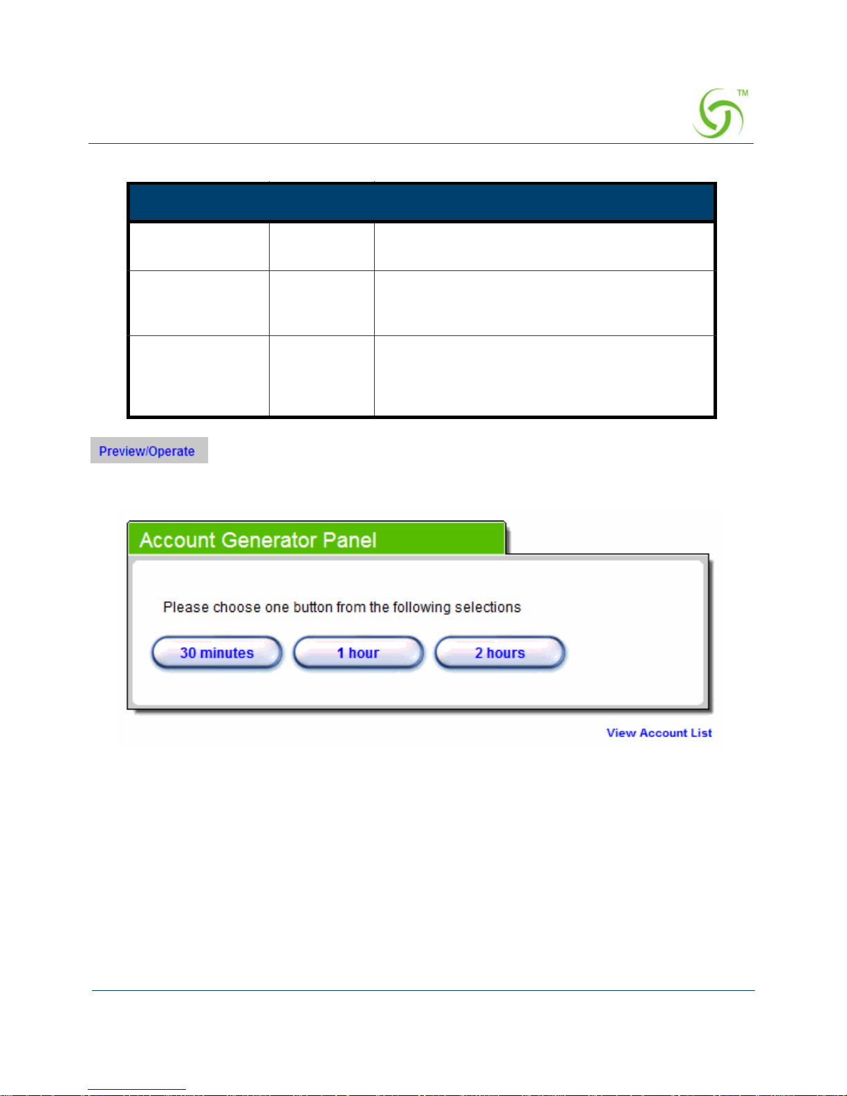
Click on button to preview and operate account generator panel.
Figure 58 Account Generator Panel
Item Default Description
Button A~C - Define each button’s billing profile. Select one
billing profile by clicking in the list box.
Print to… Account
Generator
Printer
Select a printer to print out your account.
Use ~ for
Discount Price
Plan based on
“Button Presses”
Button A,
Disable
Select one button (A~C) by clicking in the list
box to assign the base charge and select enable
to active the discount price plan.

ACCESS GATEWAY
70 Configuring the Wireless Connect Gateway
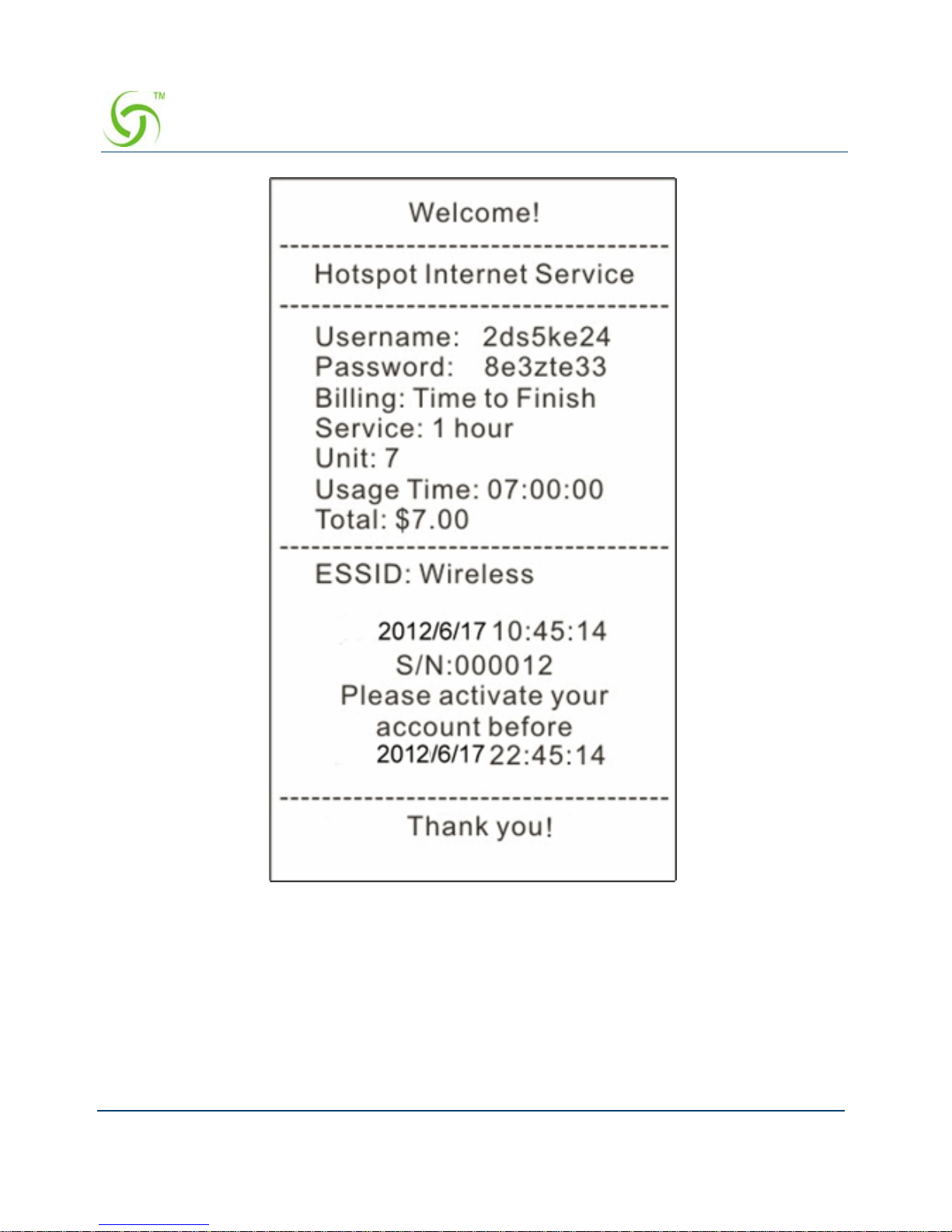
Figure 59 Web-based Account Generator Printout (Time to Finish)

ACCESS GATEWAY
Configuring the Wireless Connect Gateway 71
Figure 60 PC-connected Printer Printout (Time to Finish)

ACCESS GATEWAY
72 Configuring the Wireless Connect Gateway
Figure 61 Web-based Account Generator Printout (Accumulation)

ACCESS GATEWAY
Configuring the Wireless Connect Gateway 73
Figure 62 PC-connected Printer Printout (Accumulation)
Note: Before configuring the accounting, you have to setting the billing profile of Web-based
account generator panel.
Example: If press 7 times
Discount Price Plan based on “Button Presses” is disabled.

ACCESS GATEWAY
74 Configuring the Wireless Connect Gateway
Figure 63 Example 1
Figure 64 Account Printout
Amount: 7 x $2.00= $14.00
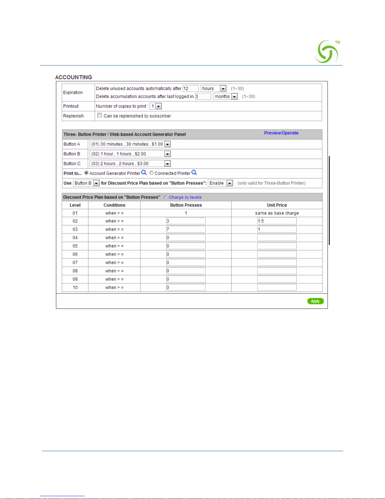
Discount Price Plan based on “Button Presses” is enabled.
The Charge by level is disabled.
ACCESS GATEWAY
Configuring the Wireless Connect Gateway 75
Figure 65 Example 2
Amount: 7 x $ 1 = $ 7.00
Below is an example of the account printout.
ACCESS GATEWAY
76 Configuring the Wireless Connect Gateway
Figure 66 Account Printout
Discount Price Plan based on “Button Presses” is enabled.
Charge by level is enabled.
ACCESS GATEWAY
Configuring the Wireless Connect Gateway 77
Figure 67 Example 3
Amount: 2 x $2.00 + 4 x$ 1.50+1x$1= $11.00
Below is an example of the account printout.

ACCESS GATEWAY
78 Configuring the Wireless Connect Gateway
Figure 68 Account Printout
Discount Price Plan based on “Button Presses”

ACCESS GATEWAY
Configuring the Wireless Connect Gateway 79
Figure 69 Discount Price Plan Setting Screen
Click Apply button to save the new settings.
Click Apply button, the success dialog box appears. Click on Back to return to Accounting
setting screen.
Item Default Description
Charge by
levels
Enable Enables or disables the charge by levels function.
Level 1~10 This field displays the level number of charge rate.
Conditions When>=The discount condition.
Button
Presses
- Enter the times of pressing button.
Unit Price - Enter the amount of charge level.

ACCESS GATEWAY
80 Configuring the Wireless Connect Gateway
Figure 70 Success Dialog Box
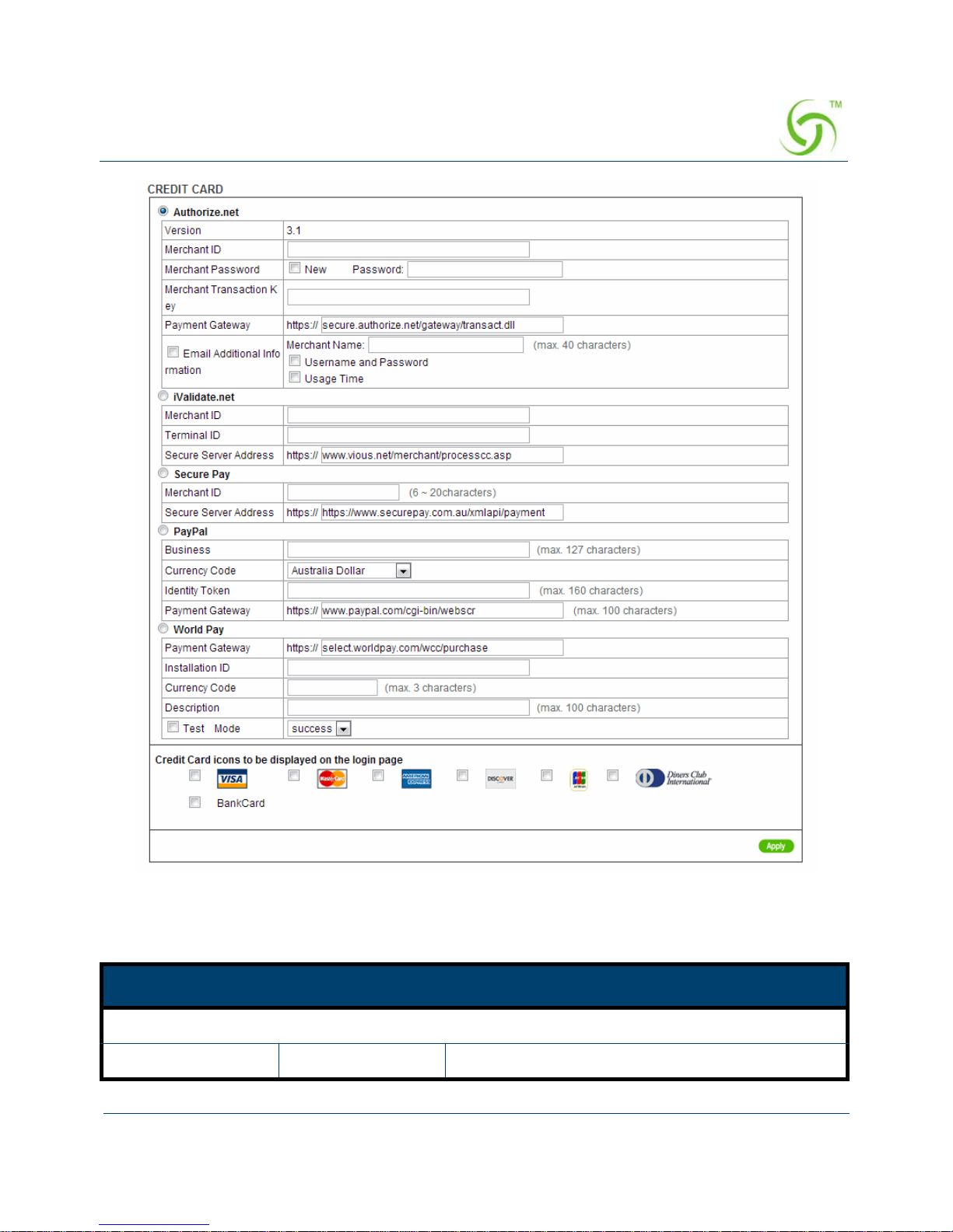
Credit Card
Wireless Connect Gateway provides three credit card services (Authorize.net, iValidate.net,
Secure Pay and Paypal) that allow service provider to authorize, process, and manage credit
transactions directly from Internet.
ACCESS GATEWAY
Configuring the Wireless Connect Gateway 81
Figure 71 Credit Card Setting Screen
Item Default Description
Authorize.net
Version 3.1 This field displays the merchant version.

ACCESS GATEWAY
82 Configuring the Wireless Connect Gateway
Merchant ID Empty Enter your Merchant ID. This is a Merchant
Identification Number that you have received from
your Merchant Provider. The maximum characters
of the Merchant ID is 50.
Merchant Password This is a Merchant password that you have received from your Merchant
Provider.
Need Disable If your Merchant Provider needs a password to
authorize, click the check box to enable this
function.
Password Empty Enter your Merchant password.
Merchant
Transaction Key
Empty The Merchant Transaction Key can be obtained
directly from “Authorize.net”. The Merchant
Transaction Key is similar to a password and is
used by the Payment Gateway to authenticate
transactions. The maximum characters of the
Merchant Transaction Key is 50.
Payment Gateway https://
secure.authorize.n
et/gateway/
transact.dll
Enter the address of the Payment Gateway.
Email Additional
Information
The Email additional Information will include The following configured
items
Email Additional
Information
Disable Indicates whether Email additional information
should be sent to the subscriber
Merchant Name
Enable/Disable
Disable Indicates whether Merchant Name should be sent
to the Email of the subscriber.
Merchant Name Empty Enter the merchant’s company name. The
maximum allowed characters is 40.
Username and
Password Enable/
Disable
Disable Indicate if The subscriber’s username and
password would be sent to subscriber
Usage Time Enable/
Disable
Disable Indicate if subscriber usage time would be sent to
the subscriber.
iValidate.net
Item Default Description

ACCESS GATEWAY
Configuring the Wireless Connect Gateway 83
Merchant ID Empty Enter your Merchant ID. This is a Merchant
Identification Number that you have received from
your Merchant Provider. The maximum characters
of the Merchant ID are 20.
Device ID Empty Enter your Device ID. This is a Device
Identification Number that you have received from
your Merchant Provider. The maximum characters
of the Device ID is 20.
Item Default Description
Secure Server
Address
https://
www.vious.net/
merchant/
processcc.asp
Enter the secure server address.
Secure Pay
Merchant ID Empty Enter your Merchant ID. This is a Merchant
Identification Number that you have received from
your Merchant Provider. The maximum characters
of the Merchant ID is 7.
Secure Pay Address https://
www.securepay.co
m.au/securepay/
payments/
process2.asp
Enter the address of SecurePay Payment
Gateway.
PayPal
Business Empty Enter your Merchant PayPal account. This is a
Merchant Identification account that you have
register on PayPal.
The maximum characters of the Business is 127.
Currency Code U.S. Dollar The Drop-down list Includes Australia dollar,
Canadian Dollar, Euro, Pound Sterling, Japanese
Yen , U.S. Dollars, Czech Koruna, Danish Kroner,
Hong Kong Dollars, Hungarian Forint, New
Zealand Dollars, Norwegian Kroner, Polish Zloty,
Singapore Dollars, Swedish Kronor, Swiss Francs,
Item Default Description

ACCESS GATEWAY
84 Configuring the Wireless Connect Gateway
Click the Apply button to save the new settings.
Identity Token Empty Enter the Identities token from merchants profile in
the PayPal site.
The maximum characters of the Identity token is
160.
Payment Gateway https://
www.paypal/cgibin/webscr
Enter the address of Payment Gateway.
The maximum characters of the payment gateway
are 100.
Note
:
Please leave the Administrator’s Email address in Advanced/Syslog/Email portion.
Credit Card icons to
be displayed on the
login page
VISA Click on check box to display credit card icon on
the login page.
Item Default Description
World Pay The currently support currencies are as follows: GBP (Pounds Sterling),
Japanese Yen, AUD (Australian dollar), CAD (Canadian Dollar), Eur
(Euro), New Zealand Dollar, Indian Rupee, Singapore dollar and USD
(US Dollar).
Payment Gateway Enter the payment gateway address. The default value is
“select.worldpay.com/wcc/purchase”.
Installation ID Empty The unique reference number, assigned by
WorldPay, for a particular Select installation. This
is the number you send to WorldPay in your
payment form. You will probably have at least two
of these; one for the live installation and one for
testing.
Currency Code Empty Enter the currency code.
Description Empty Enter a description of payment page.
Test Mode Disable, Success Enables or disables test mode function.
Select test mode by clicking in the list box.
Success ─ to make a successful test transaction.
Fail ─ for a failed transaction.
Item Default Description

ACCESS GATEWAY
Configuring the Wireless Connect Gateway 85
Click the Apply button, the success dialog box appears. Click on Back to return to Accounting
setting screen.
Figure 72 Success Dialog Box
Please follow steps below to pay using credit card.
Step 1: Choose Credit Card service on the login page.
Figure 73 Login Page
Click
Click

ACCESS GATEWAY
86 Configuring the Wireless Connect Gateway
Figure 74 Service & Payment Information Setting Screen (Authorize.net)
Currency: American Dollars

ACCESS GATEWAY
Configuring the Wireless Connect Gateway 87
Step 2: Select Service and enter payment information.
Item Default Description
Payment Information
Credit card number Empty Enter your credit card number.
Credit card expiration
date
Empty Enter the credit card expiration date. The allowed
format is MMYY.
Enter Email Address Empty Enter your email address. The system will e-mail
you account information once your payment
information has been successfully authorized.
First Name, Last
Name…..
Empty Enter the customer information, including name,
city, country and ZIP/Postal Code.

ACCESS GATEWAY
88 Configuring the Wireless Connect Gateway
Figure 75 Service & Payment Information Setting Screen (iValidate.net)
Item Default Description
Payment Information
Credit card number Empty Enter your credit card number.

ACCESS GATEWAY
Configuring the Wireless Connect Gateway 89
Credit card expiration
date
Empty Enter the credit card expiration date. The allowed
format is MMYY.
Enter Email Address Empty Enter your email address. The system will e-mail
your account information once your payment
information has been successfully authorized.
Billing Address ZIP
code
Empty Enter the ZIP code.
Item Default Description

ACCESS GATEWAY
90 Configuring the Wireless Connect Gateway
Figure 76 Service & Payment Information Setting Screen (Secure Pay)
Item Default Description
Payment Information
Credit card number Empty Enter your credit card number.

ACCESS GATEWAY
Configuring the Wireless Connect Gateway 91
Figure 77 Service & Payment Information Setting Screen (PayPal and WorldPay)
Step 3: After valid payment information has been provided, the Subscriber will obtain one
valid account and the login screen will appear.
Credit card expiration
date
Empty Enter the credit card expiration date. The allowed
format is MMYY.
Enter Email Address Empty Enter your email address. The system will e-mail
your account information once your payment
information has been successfully authorized.
Item Default Description

ACCESS GATEWAY
92 Configuring the Wireless Connect Gateway
Figure 78 User Account Information

ACCESS GATEWAY
Configuring the Wireless Connect Gateway 93
Figure 79
MANAGEMENT
LAN Devices
Administrator can control LAN Devices via the Wireless Connect Gateway.

ACCESS GATEWAY
94 Configuring the Wireless Connect Gateway
Figure 80 LAN Devices Setting Screen
Item Default Description
Polling Interval 5 Min. The default value is 5 minutes. The Polling Interval valid
range is 1 to 1440.
Device Name Empty The LAN device name. The maximum characters of the
device name are 20.
Virtual Port 0 The virtual port number valid range is 60001 to 60050 or
5900 to 5910.
Device IP
Address
Empty Enter the IP address of LAN device in the format
“xxx.xxx.xxx.xxx”
Device Server
Port
0 Enter the server port of LAN device.

ACCESS GATEWAY
Configuring the Wireless Connect Gateway 95
Click Apply button to save the new settings.
Note: The system does not support FTP.
Syslog
The function allows the device to transmit event messages to your syslog server or your email
address for monitoring and troubleshooting.
Syslog Setting
Figure 81 Syslog Setting Screen
Device MAC
Address
Empty The MAC address of LAN device. For inputting the device
MAC address, please use this format such
like”0050BA8D2296”.
Application TCP Select one protocol type for the LAN device by clicking in
the list box.
Item Default Description

ACCESS GATEWAY
96 Configuring the Wireless Connect Gateway
Item Default Description
Syslog Disable Enables or disables the syslog server function.
Syslog on LAN
Server IP
Address
Empty Enter syslog server’s IP address. The Wireless Connect
Gateway will send all of its logs to the specified syslog
server.
Server MAC
Address
Empty Enter the syslog server’s MAC address. The Wireless
Connect Gateway will send all of its logs to the specified
syslog server.
Syslog on WAN
Server 1 IP
Address
Empty Enter IP address of first syslog server.
Server 2 IP
Address
Empty Enter IP address of second syslog server.
Send to Email Disable Enables or disables the send to e-mail function.
E-mail Server
IP Address or
Domain Name
Empty Enter the SMTP server IP address or domain name.
The maximum allowed characters length is 50.
SMTP Port 25 The SMTP port allowed range is 25 or 2500 to 2599.
E-mail (SMTP)
Server needs to
check my
account
Disable If your SMTP server requires authentication before
accepting e-mail, click on check box. These values
(username and password) are supplied by your network
administrator, SMTP server provider or ISP.
Username Empty Enter the username for the SMTP server. The maximum
allowed characters length is 64.
Password Empty Enter the password for the SMTP server
Email From
Name Empty Enter the name you would like to appear in the
“message from” field of your outgoing message. The
maximum allowed characters length is 20.

ACCESS GATEWAY
Configuring the Wireless Connect Gateway 97
Click Apply button to save the new settings.
Figure 82 Success Dialog Box
Click Apply button, the success dialog box appears. Click on Back to return to Syslog setting
screen
Email Address Empty Enter your e-mail address. This is the address others
will use to send email to Email Address 1/Email Address
2.
Email To
Email Address 1 Empty Enter your first e-mail address to receive the logs.
Email Address 2 Empty Enter your second e-mail address to receive the logs.
Item Default Description

ACCESS GATEWAY
98 Configuring the Wireless Connect Gateway
Log Categories
Figure 83 Log Settings Screen
 Loading...