

Page 1
GATEWAY QUICK START GUIDE
About this Guide
This Quick Start Guide provides instructions and reference material for getting started with the Nomadix Access Gateway
Products, specifically the AG 2500, AG 5900 and EG 6000.
Documentation and Technical Support
For more detailed information about the individual gateways and all other Nomadix Product Documentation, User Guide,
XML DTD, MIB and Radius Dictionary can be found using the following URL:
http://www.nomadix.com/technical-support-documentation
If you have any problems, please contact our technical support team at +1.818.575.2590, or via email: [email protected]
Accessory Box Contents
The AG 2500, AG 5900 and EG 6000 are shipped with the following Accessory Box to assist with product installation.
Contents varies depending on what was ordered.
Accessory Box
Qty Description Comments
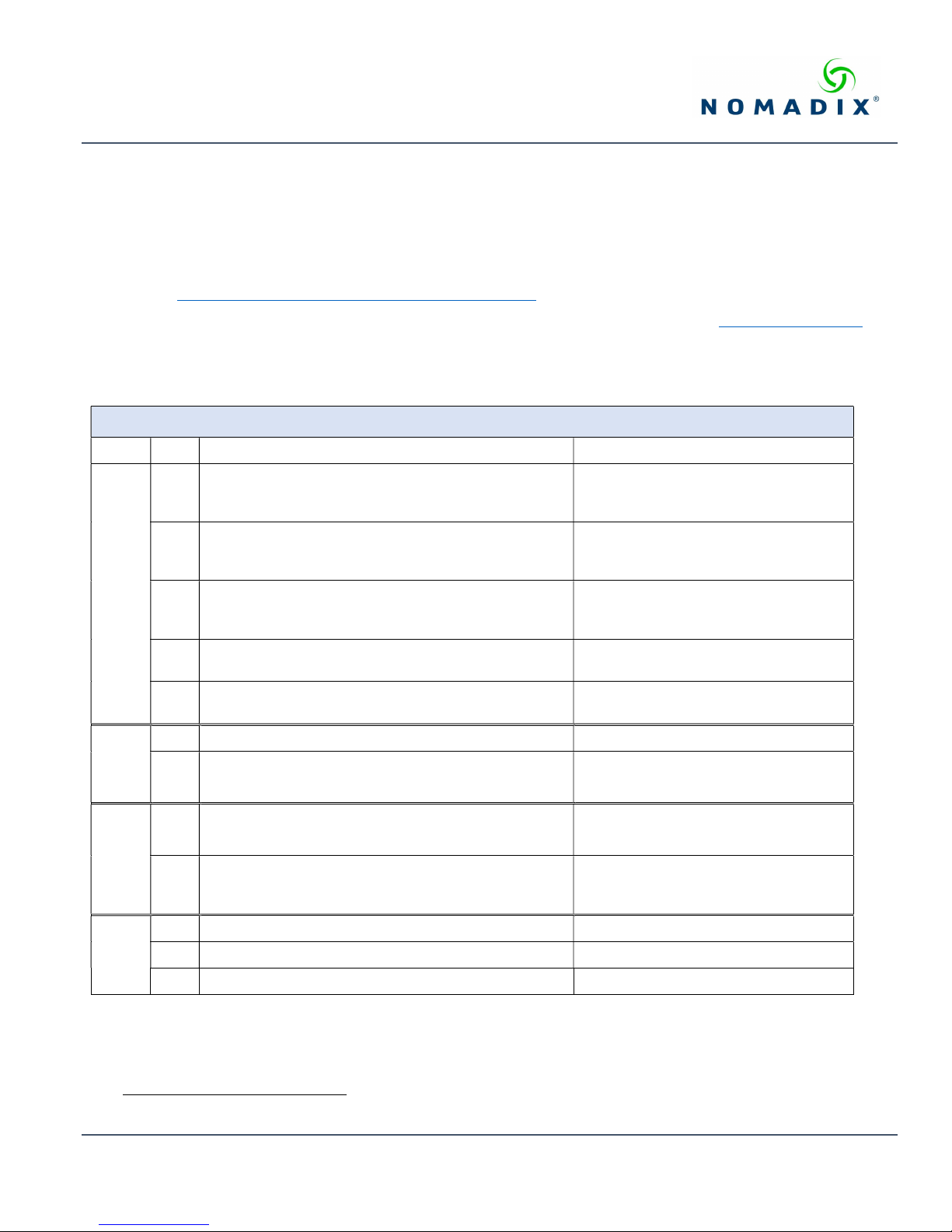
1 1.8m U.S. (NEMA 5-15p) Power Cord (Type B): United
States, Canada, Mexico and Japan.
1 1.8m EU Schuko CEE7/7 Power Cable (Type F): Most
everywhere in Europe and Russia except for UK and
Ireland.
1 1.8m U.K. Power Cord (BS1363 Type G): used in the
United Kingdom, Ireland, Malaysia, Singapore and Hong
power cords
Kong.
1 1.8m China Standard (Type I) 3 Prong GB 2099 Power
Cord, used in China, Australia , New Zealand, Argentina.
1 1.8m India (Type D), 3 Prong Power Cord, used mainly in
India.
Included with product shipped in North
America and Mexico.
(part no. 715-4001-004)
Optional item: (part no. 715-4001-003)
Optional item: (part no. 715-4001-005)
Optional item: (part no. 715-4001-006)
Optional item: (part no. 715-4001-007)
1 1.8m RJ45 – DB9S Console Cable (Black) AG 2500 and AG 5900 only
1 1.8m EG 6000 USB to DB9 Console Cable AG 6000 only:
cables
console
1 RJ45 – DB9 Adaptor (Grey)
PMS connection
1 RJ45 -DB9S PMS Adaptor (part number 715-4001-002)
and Optical Isolator 715-4001-009)
adaptors
1 19” Rack Mount Brackets Kit 1 and screws. All Products
1 Power Transformer and mounting bracket AG 2500 only
misc.
items
1 Bumper Kit for desktop installations. All Products
Optional Item: 715-4001-001
AG 2500 and AG 5900 only
EG 6000 only. Not sold separately.
Included with EG 6000 Hospitality PMS
Software Module (716-6017-001)
1
Rack Mount Bracket are different for the AG 2500 and AG 5900/EG 6000
May 2019 Information subject to change without notice. 1
Page 2
GATEWAY QUICK START GUIDE
Installation and Cabling
1. Unpack the Nomadix Access Gateway and place the product on a flat and stable work surface.
2. Register the gateway for support services by completing and returning the Nomadix Gateway Registration Form - hardcopy
enclosed or obtain the form online at the following URL: http://www.nomadix.com/registration.html
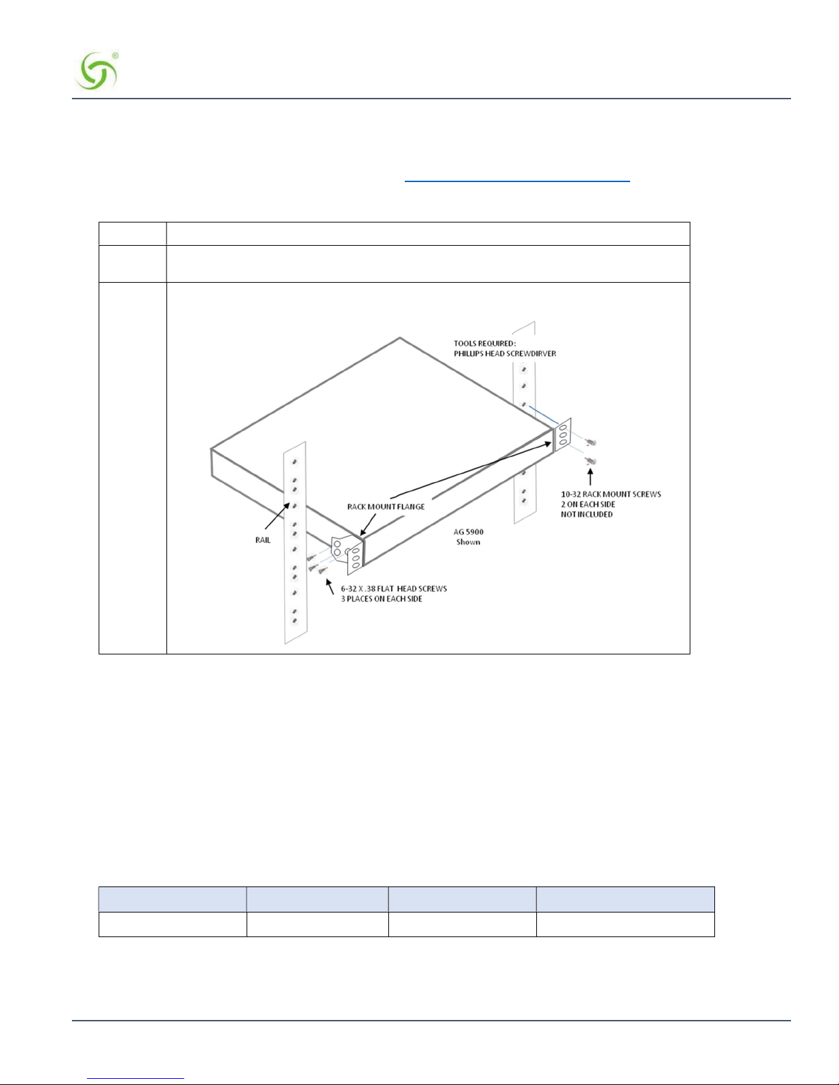
3. Install the Rack Mount brackets to the Nomadix Access Gateway and install in the 19” rack.
AG 5900/EG 6000 (Example)
Step #1 Install the Rack Mounting Flanges to each side of the AG 2500 or AG 5900/EG 6000: using
the 6-32 flat head screws.
Step #2 Using (4) 10-32 rack mounting screws, position the AG in the rack and secure to the vertical
rails.
4. Connect the power cord.
5. For the initial configuration connect to the AG 2500, AG 5900 or EG 6000, either a serial asynchronous connection or
Ethernet connection described below:
Initializing the Gateway
There are (2) methods to initialize/start-up the Gateway, most common is via the WAN Ethernet port or alternatively by using the
asynchronous RJ45 port on the AG 2500 or AG 5900, or the USB the console port on the EG 6000, both configurations are
depicted below:
Ethernet Port Connection
Configure the laptop’s network setting to use the following Administration IP address settings [Table 1].
IP Address Netmask Gateway DNS (if needed)
172.30.30.173 255.255.0.0 172.30.30.172 4.2.2.1
Table 1: Administrative IP address
Nomadix Inc. 2
Page 3
GATEWAY QUICK START GUIDE
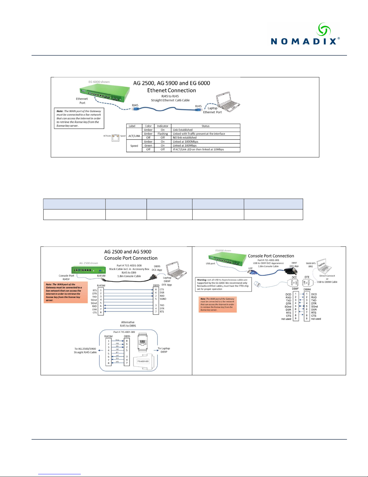
Install the Ethernet cable between the AG 2500, AG5900 or the EG 6000 Eth1 port and the laptop’s Ethernet port and check
the status as shown [illustration 1].
Illustration 1: Ethernet connection and status
Asynchronous Console Port Connection
On the PC/laptop start the asynchronous terminal emulation application, using PuTTY, Hyperterm, Procomm (or equivalent)
application using the following configuration parameters for the comm port [Table 2].
Bits Per Second Data Bits Parity Stop Bits Flow Control
9600 8 NONE 1 NONE
Table 2: Comm port settings.
On the AG 2500 and AG5900 use the RJ45 console port, on the EG 6000 use the USB console port. Please note: the EG 6000
console port is only on the USB port. Both methods are depicted below [illustration 2]:
Illustration 2: Console Port connections
With everything connected and powered up, you are now ready to configure the configure the Gateway’s WAN for a static IP
address, DHCP Client or PPPoE client using appropriate configuration guidelines that follow in order to obtain the license key.
Once the key has been obtained, the web management interface (WMI) can be used to continue and finish the configuration.
May 2019 Information subject to change without notice. 3
Page 4
GATEWAY QUICK START GUIDE
Note: The WAN port of the Gateway must be connected to a live network that can access the Internet in order to retrieve the
license key from the license key server.
Initial (startup) Configuration
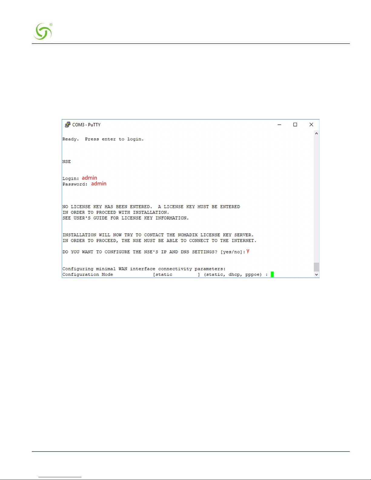
Log in to the Gateway, by opening an SSH to 172.30.30.172 or the asynchronous comm port, using the default Login= admin and
password= admin. Type y[es] when prompted to configure settings.
The initial minimal WAN port configuration mode will be displayed as shown in Figure 1.
Figure 1: Initial minimal WAN port configuration.
Select the desired configuration mode and use the following steps to configure the WAN port for either Static IP, DHCP client or
PPPoE.
Nomadix Inc. 4
Page 5
GATEWAY QUICK START GUIDE
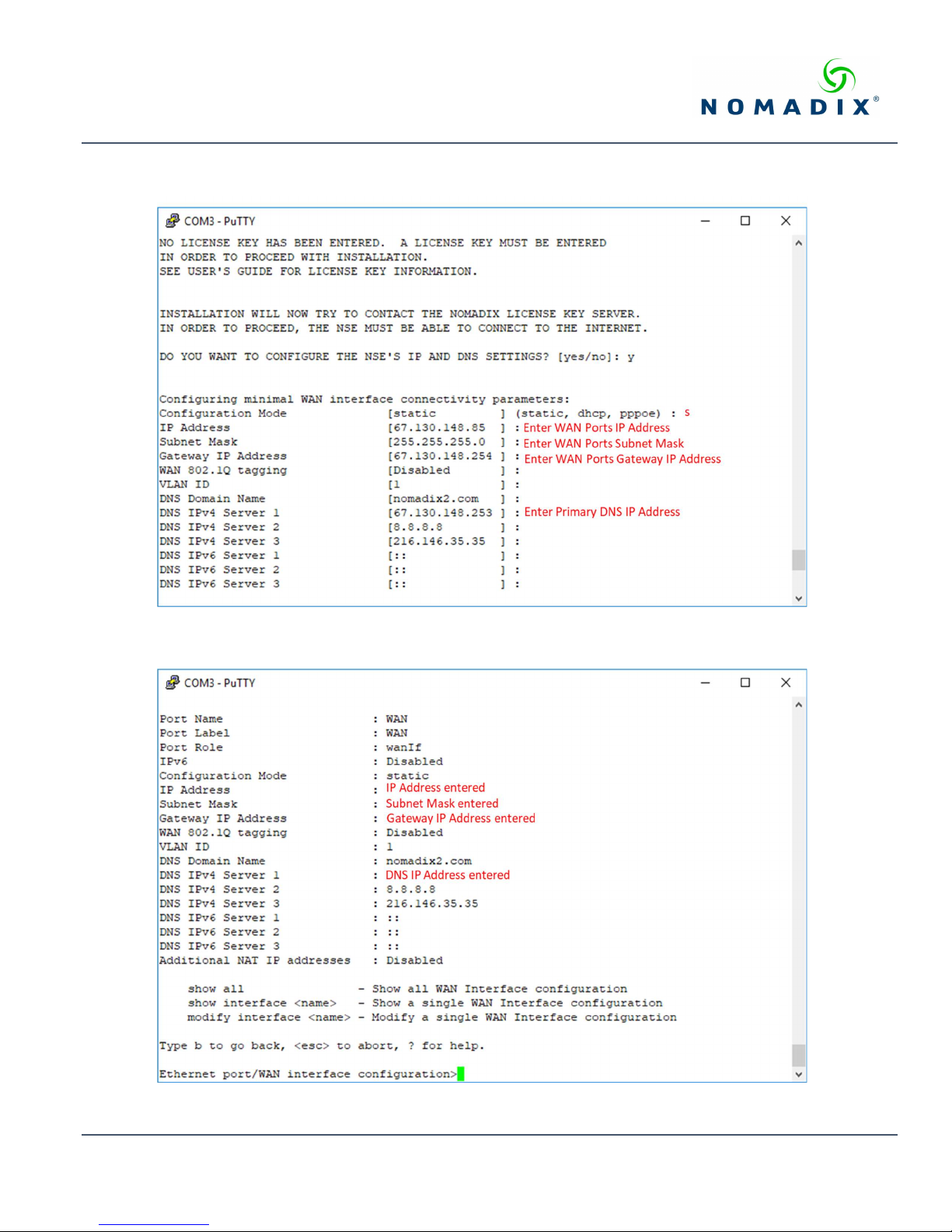
Step 1a: Static WAN IP Configuration
Accept static as the default configuration mode and enter the following mandatory settings shown in Figure 2.
Figure 2: Initial WAN port settings
A WAN port summary page will then be displayed as shown in Figure 3.
Figure 3: WAN port static IP configuration summary page
May 2019 Information subject to change without notice. 5
Page 6
GATEWAY QUICK START GUIDE
If everything is correct in the summary, type b[ack] to return to the previous menu and proceed to Step 2 to enter the location
information.
Otherwise, select an option from the Ethernet port configuration menu to display or make changes to the WAN port settings.
When finished with the settings, type b[ack] to return to the previous menu and proceed to Step 2 to enter the location
information.
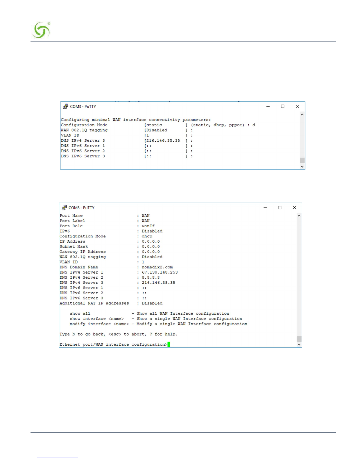
Step 1b: DHCP Client Configuration
Type d[hcp] for the configuration mode as shown in Figure 4.
Figure 4: Selecting DHCP Client for WAN configuration
A WAN port summary page will then be displayed as shown in the example Figure 5.
Figure 5: WAN port DHCP client configuration summary page
If everything is correct in the summary, type b[ack] to return to the previous menu and proceed to Step 2 to enter the location
information.
Otherwise, select an option from the Ethernet port configuration menu to display or make changes to the WAN port settings.
When finished with the settings, type b[ack] to return to the previous menu and proceed to Step 2 to enter the location
information.
Nomadix Inc. 6
Page 7
GATEWAY QUICK START GUIDE
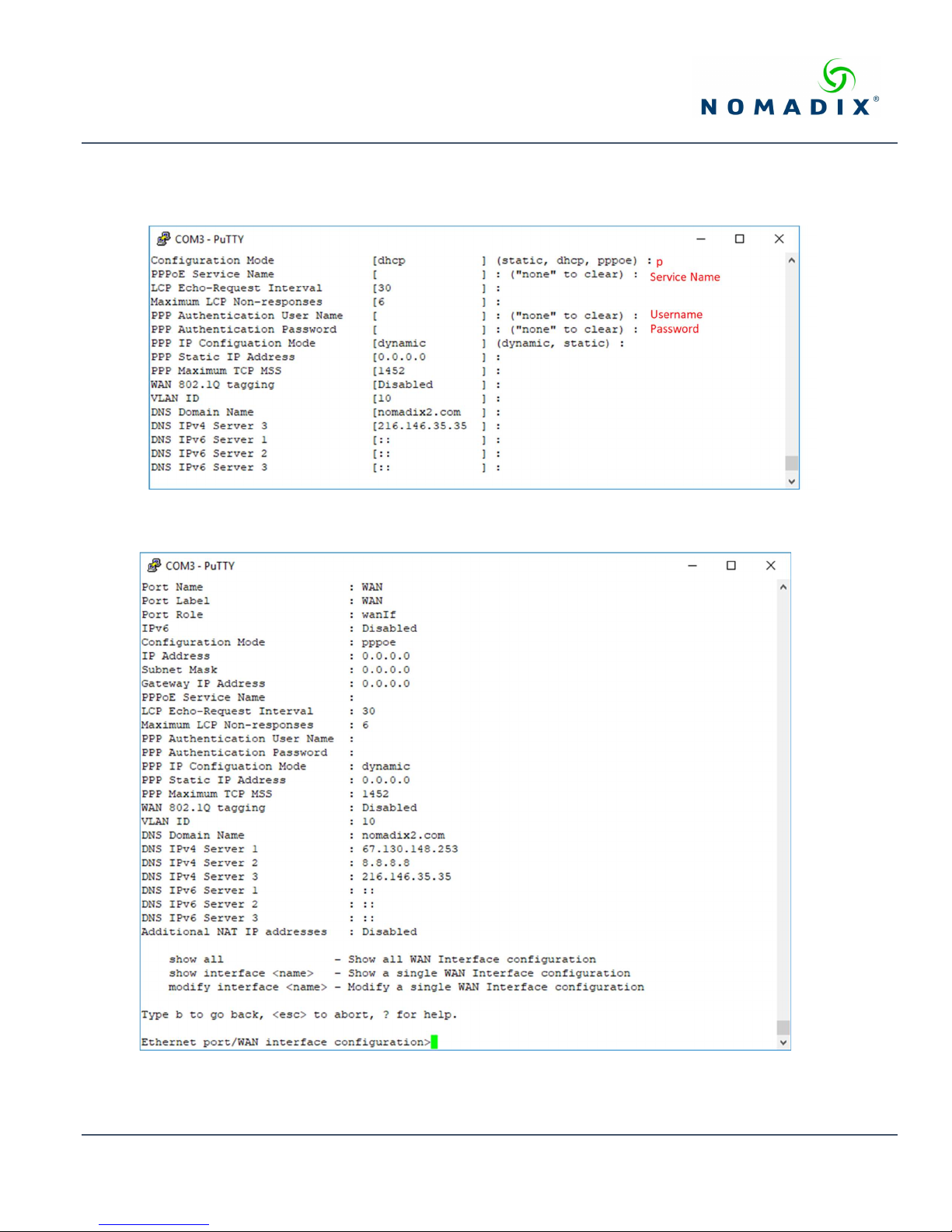
Step 1c: PPPoE Dynamic IP Client Configuration
Enter p[ppoe] when prompted. Enter the following mandatory settings for a PPPoE connection with dynamic PPP IP
configuration shown in Figure 6.
Figure 6: Selecting PPPoE with dynamic IP configuration
A WAN port summary page will then be displayed as shown in Figure 7.
Figure 7: WAN port PPPoE client configuration summary page
May 2019 Information subject to change without notice. 7
Page 8
GATEWAY QUICK START GUIDE
Step 1d: PPPoE Static IP Client Configuration
Use the same steps for configuring dynamic PPPoE shown in Figure 6 above, but select static for PPP IP Configuration Mode, and
enter your IP address for PPP Static IP Address. A summary page similar to Figure 7 above will be displayed.
If everything is correct in the summary, type b[ack] to return to the previous menu and proceed to Step 2 to enter the location
information.
Otherwise, select an option from the Ethernet port configuration menu to display or make changes to the WAN port settings. When
finished with the settings, type b[ack] to return to the previous menu and proceed to Step 2 to enter the location information.
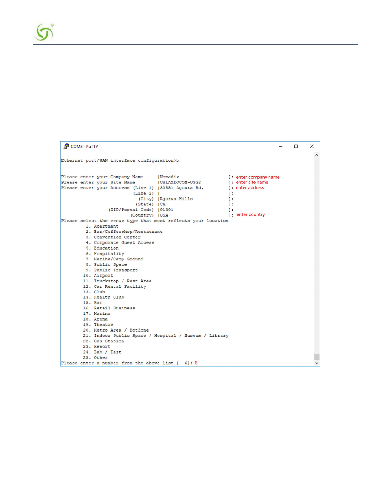
Step 2: Entering Your Location Information
You will be required to enter location information to obtain the license key. Enter the following mandatory location information
details shown in Figure 8.
Figure 8: Site location details
Step 3: Retrieving Your License Key
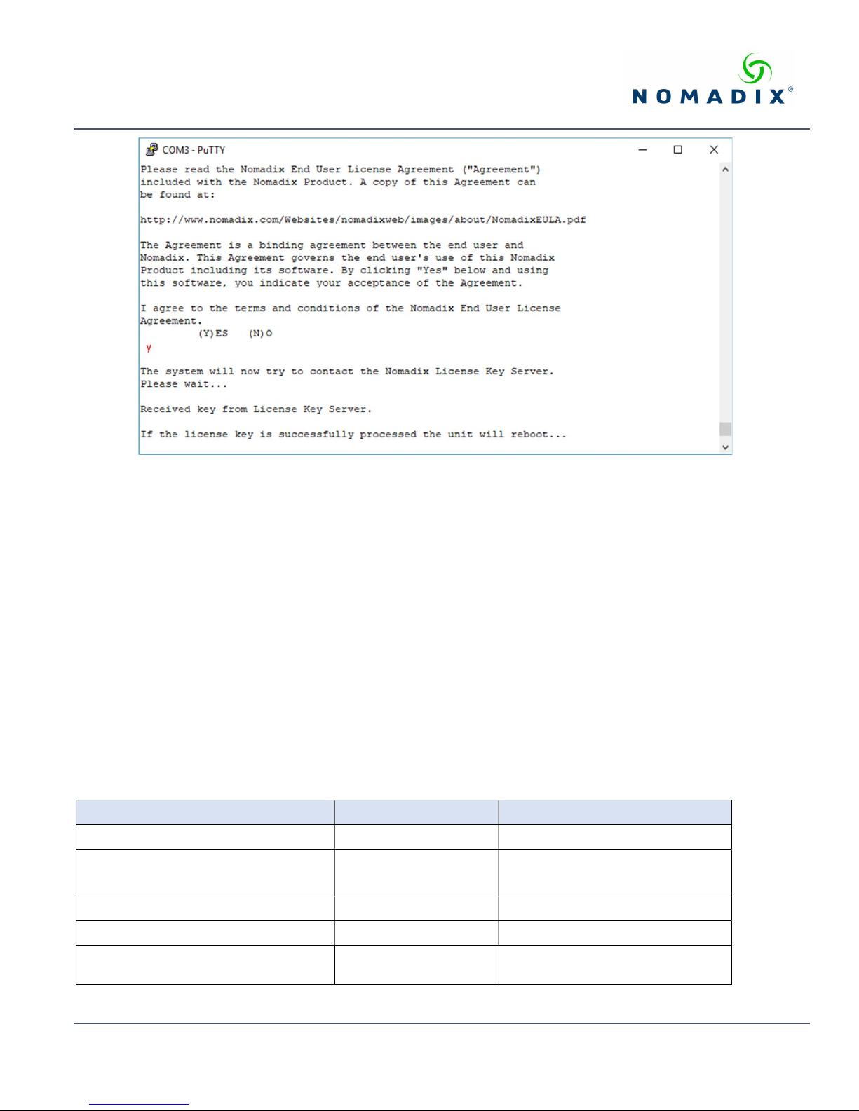
The system will now prompt you to accept or decline the End User License Agreement (EULA). You must accept the terms of the
EULA before the AG can retrieve its license key. To retrieve the license key, enter y[es] as shown in Figure 9. The AG retrieves
the license key from the Nomadix license key server, then reboots.
Nomadix Inc. 8
Page 9
GATEWAY QUICK START GUIDE
Figure 9: License key retrieval.
NOTE: The date and time the gateway receives a valid license from our server for the first time is considered the Software License
Subscription start date.
Step 4: Configuring the System
Log in to the AG and use the graphical Web Management Interface (WMI) to configure the product’s features. You have now
established a basic configuration for the AG that enables internet connectivity.
For additional information about the available AG features, refer to Chapter 2 of the User Guide specific to your AG. For
example:
To establish various billing and authentication methods, see Defining the AAA Services.
To establish hotel billing, see Assigning a PMS Service.
Step 5: Configuring AG DHCP Server Settings
DHCP Server is enabled by default. To configure the DHCP Server, go to DHCP under the Configuration menu. You can either
modify the default DHCP pool or delete/add another DHCP pool. The total lease pool size recommendation is 75% more than the
number of licensed subscribers. Table 3 shows the factory default DHCP server settings.
DHCP Parameters Your Settings Default Values
DHCP Services (Disable) no
DHCP Relay (Yes / No)
If No, skip to DHCP Server
DHCP Relay Server IP Address blank
DHCP Relay Agent IP Address blank
DHCP Server (Yes / No)
Only if the DHCP Relay is disabled
no
yes
May 2019 Information subject to change without notice. 9
Page 10
GATEWAY QUICK START GUIDE
DHCP Server IP Address 10.0.0.4
DHCP Server Subnet Mask 255.255.255.0
DHCP Pool Start IP Address 10.0.0.12
DHCP Pool End IP Address 10.0.0.72
DHCP Lease Minutes 1440
Table 3: DHCP server configuration
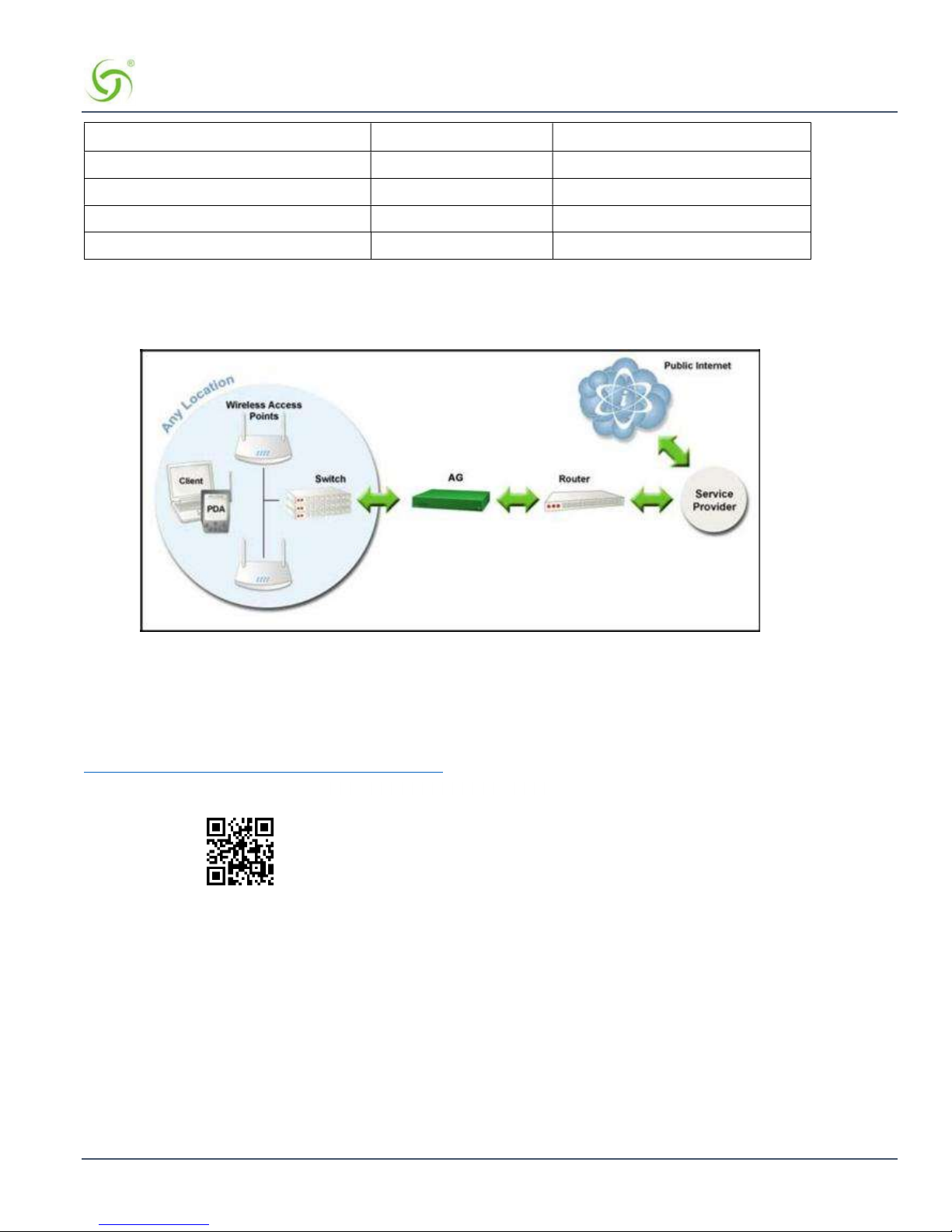
Sample Network Setup
An example of a basic network including an AG is shown in Figure 10.
Figure 10: Example of a network setup
Additional Documentation
Additional Product documentation can be found at:
http://www.nomadix.com/technical-support-documentation
Nomadix Product Documentation
Nomadix Inc. 10
 Loading...