


ACCESS GATEWAY
Access Gateway
Copyright © 2017 Nomadix, Inc. All Rights Reserved.
This product also includes software developed by: The University of California, Be rkeley and its contributors;
Carnegie Me llon University, Copyright © 1998 by Carnegie Mello n University All Rights Reserved; Go
Ahead Software, Inc., Copyright
© 1999 Go Ahead Software, Inc. All Rights Reserved; Livingston E nt erprises, Inc., Copyright © 1992
Livingston Enterprises, Inc. All Rights Reserved; The Regents of the University o f Michigan and Mer it
Network, Inc., Copyright 1992 – 1995 All Rights Reserved; and includes source code covered by the Mozilla
Public License, Version 1.0 and OpenSSL.
This User Guide is protected by U.S. c opyright laws. You may not transmit, copy, modify, or translate this
manual, or reduce it or any part of it to any machine readable form, without the express permissio n of the
copyright holder.

ACCESS GATEWAY
Trademarks
The symbol, and Nomadix Service Engine® are registered trademarks of Nomadix, Inc. All other
trademarks and brand names are marks of their respective holders.
Product Information
Telephone: +1.818.597.1500
Fax: +1.818.597.1502
For technical support information, see the Appendix in this User Guide.
Write your product serial number in this box:
Patent Information
Please see the Nomadix website for a list of US and foreign patents covering this product release.
Disclaimer
Nomadix, Inc. makes no warranty, either express or implied, including but not limited to any implied
warranties of merchantability and fitness for a particular purpose, regarding the product described herein. In
no event shall Nomadix, Inc. be liable to anyone for special, collateral, incidental, or consequential damages
in connection with or arising from the use of Nomadix, Inc. products.

ACCESS GATEWAY
WARNING
CAUTION
AVERTISSEMENT
ATTENTION
WARNUNG
ACHTUNG
AVISO
PRECAUCIÓN
Risk of electric shock; do not open; no user-
serviceable parts inside.
Risque de choc electrique; ne pas ouvrir; ne pas
tenter de demontre l’appareil
Nicht öffnen; elektrische Bauteile.
Riesgo de shock eléctrico. No abrir. No hay
piezas configurables dentro.
Read the instruction manual prior to operation.
Lire le mode d’emploi avant utilisation.
Lesen Sie das Handbuch bevor Sie das Gerät in
Betrieb nehmen.
Leer el manual de instrucciones antes de poner
en marcha el equipo.
30851 Agoura Rd, Suite 102, Agoura Hills, CA 91301 USA (head office)

ACCESS GATEWAY
Table of Contents
Introduction ................................................................................................................................................................. 1
About this Guide .......................................................................................................................................................... 1
Organization ................................................................................................................................................................ 2
Welcome to the Access Gateway ................................................................................................................................ 3
Product Configuration and Licensing ................................................................................................................ 3
Key Features and Benefits .......................................................................................................................................... 4
Platform Reliability .............................................................................................................................................. 4
Local Content and Services ................................................................................................................................. 4
Transparent Connectivity .................................................................................................................................... 4
Billing Enablement ............................................................................................................................................... 5
Access Control and Authentication ..................................................................................................................... 5
Security .................................................................................................................................................................. 5
5-Step Service Brandi ng ....................................................................................................................................... 5
NSE Core Functionality .............................................................................................................................................. 7
Access Control ...................................................................................................................................................... 8
Bandwidth Management ...................................................................................................................................... 8
Billing Records Mirroring ................................................................................................................................... 9
Bridge Mode .......................................................................................................................................................... 9
Class-Based Queueing .......................................................................................................................................... 9
Command Line Interface ................................................................................................................................... 12
Daylight Savings Time and IANA Time Zone Support ................................................................................... 12
Dynamic Address Translation™ ....................................................................................................................... 13
Dynamic Transparent Proxy ............................................................................................................................. 13
End User Licensee Count ................................................................................................................................... 13
External Web Server Mode ............................................................................................................................... 13
Facebook Authentication ................................................................................................................................... 13
Home Page Redirect ........................................................................................................................................... 14
iNAT™ ................................................................................................................................................................ 14
Information and Control Console ..................................................................................................................... 15
Initial NSE Configuration .................................................................................................................................. 16
Internal Web Server ........................................................................................................................................... 16
International Language Support ....................................................................................................................... 16
IP Upsell .............................................................................................................................................................. 16
IPv6 Device Management .................................................................................................................................. 17
i

ACCESS GATEWAY
Link Aggregation Control Protocol (LACP) .................................................................................................... 17
Logout Pop-Up Window .................................................................................................................................... 17
MAC Filtering ..................................................................................................................................................... 17
Multi-Level Administration Support ................................................................................................................ 17
Multi-WAN Interface Management .................................................................................................................. 17
NTP Support ....................................................................................................................................................... 18
PayPal .................................................................................................................................................................. 18
Portal Page Redirect ........................................................................................................................................... 18
RADIUS-driven Auto Configuration ................................................................................................................ 18
RADIUS Client ................................................................................................................................................... 18
RADIUS Proxy ................................................................................................................................................... 19
Realm-Based Routing ......................................................................................................................................... 19
Remember Me and RADIUS Re-Authentication ............................................................................................. 19
Secure Management ........................................................................................................................................... 19
Secure Socket Layer (SSL) ................................................................................................................................ 20
Secure XML API ................................................................................................................................................ 20
Session Rate Limiting (SRL) ............................................................................................................................. 20
Session Termination R e direct............................................................................................................................ 21
Smart Client Support ......................................................................................................................................... 21
SNMP Nomadix Private MIB ............................................................................................................................ 21
Static Port Mapping ........................................................................................................................................... 21
Tri-Mode Authenti c ation ................................................................................................................................... 21
URL Filtering ...................................................................................................................................................... 21
Walled Garden .................................................................................................................................................... 22
Web Management Interface .............................................................................................................................. 22
Weighted Fair Queueing .................................................................................................................................... 22
Optional NSE Module s .............................................................................................................................................. 23
Load Balancing ................................................................................................................................................... 23
Hospitality Module ............................................................................................................................................. 23
High Availability Module ................................................................................................................................... 23
Network Architecture (Sample) ............................................................................................................................... 24
Multiple Unit Clustering ........................................................................................................................................... 25
Identifying the Resident Gateway in a Cluster Environment ......................................................................... 25
Load Balancing and Link Failover........................................................................................................................... 27
Definitions and Conce pts ................................................................................................................................... 27
User-Based ISP Selection versus Random ISP Selection ................................................................................ 27
Traffic Balancing and Weighting ...................................................................................................................... 28
Load Balancing acr oss Multiple Low Speed Links .......................................................................................... 29
Failover to Standby ISP Link ............................................................................................................................ 29
ii

ACCESS GATEWAY
Separate Guest HSIA and Admin ISP Links, with Failover Between Each ISP Link ................................. 30
Guest HSIA Failover Only, to Admin Network ............................................................................................... 31
Sharing Guest HSIA Network and Hotel Admin Network A mong Multiple ISP Links .............................. 31
Load Balancing With Users Connected to a Preferred ISP Link ................................................................... 32
Online Help (WebHelp) ............................................................................................................................................. 33
Notes, Cautions, and Warnings ................................................................................................................................ 34
Installing the Access Gateway .................................................................................................................................. 35
Installation Workflow ............................................................................................................................................... 36
Powering Up the System ........................................................................................................................................... 37
User Manual and Documentation ............................................................................................................................ 38
Start Here ................................................................................................................................................................... 39
LCD Messages ..................................................................................................................................................... 39
Configuration ............................................................................................................................................................. 40
Step 1a: Static WAN IP Configuration ............................................................................................................. 40
Step 1b: DHCP Client Co nfiguration ............................................................................................................... 41
Step 1c: PPPoE Dynamic IP Client Configuration .......................................................................................... 42
Step 1d: PPPoE Static IP Client Configuration ............................................................................................... 44
Step 2: Entering Your Location Information................................................................................................... 44
Step 3: Retrieving Your License Key ................................................................................................................ 44
Step 4: Configuring the System ......................................................................................................................... 45
Step 5: Configuring AG DHCP Server Settings .............................................................................................. 45
The Management Interf aces (CLI and Web) .......................................................................................................... 47
Making Menu Selectio ns and Inputting Data with the CLI ........................................................................... 47
Menu Organization (Web Management Interface) ......................................................................................... 47
Inputting Data – Maximum Character Lengths .............................................................................................. 48
Online Documentation and Help ....................................................................................................................... 49
Establishing the Start U p C onfiguration ................................................................................................................. 50
Assigning Log i n U s e r Names and Passwords ................................................................................................... 50
Setting the SNMP Parameters (optional) ......................................................................................................... 51
Configuring the WAN inte r face ........................................................................................................................ 52
Enabling the Logging Options (recommended) ............................................................................................... 53
Logging Out and Pow e ring Down the System.................................................................................................. 55
Connecting the Access Gateway to the Customer’s Network ......................................................................... 55
Establishing the Basic Configuration for Subscribers............................................................................................ 56
Setting the DHCP Opt ions ................................................................................................................................. 56
DHCP Options from RFC 2132 ......................................................................................................................... 57
DHCP Dynamic Enable and Disable................................................................................................................. 59
Setting the DNS Options .................................................................................................................................... 59
Archiving Your Config uration Settings ................................................................................................................... 61
iii

ACCESS GATEWAY
Installing the Nomadix Private MIB ........................................................................................................................ 62
Obtaining the Management Information Base (MIB) file ............................................................................... 62
Configuring the Management Information Base ............................................................................................. 62
System Administration .............................................................................................................................................. 63
Choosing a Remote Connection ................................................................................................................................ 64
Using the Web Management Interface (WMI) ................................................................................................ 64
Using an SNMP Manager .................................................................................................................................. 65
Using a Telnet Client .......................................................................................................................................... 65
Logging In .................................................................................................................................................................. 66
About Your Product License .................................................................................................................................... 67
Configuration Menu .................................................................................................................................................. 68
Defining the AAA Services {AAA} .................................................................................................................... 68
Establishing Secure Administration {Access Control} .................................................................................... 75
Defining Automatic Configuration Settings {Auto Conf iguration} ............................................................... 78
Setting Up Bandwidt h Management {Bandwidth Management} ................................................................... 80
Group Bandwidth Li mit P olicy ......................................................................................................................... 81
Group Bandwidth Li mit P olicy – Operation .................................................................................................... 81
Group Bandwidth Li mit P olicy – Current Table ............................................................................................ 82
Establishing Billing Records “Mirroring” {Bill Record Mirroring} .............................................................. 82
Class-Based Queueing ........................................................................................................................................ 84
Clustering {Clustering} ...................................................................................................................................... 86
Configuring Destination HTTP Redirection {Destination HTTP Redirection} ............................................ 86
Managing the DHCP service options {DHCP} ................................................................................................. 88
Managing the DNS Options {DNS} ................................................................................................................... 91
Enabling DNSSEC Support ............................................................................................................................... 92
Managing the Dynamic DNS Options {Dynamic DNS} .................................................................................. 92
Ethernet Ports/WAN .......................................................................................................................................... 93
IPv6 Device Setup ............................................................................................................................................... 94
Link Aggregation ................................................................................................................................................ 96
Enabling Fast Forwarding ................................................................................................................................. 98
Setting the Home Page Redirection Options {Home Page Redirect} ............................................................. 99
Enabling Intelligent Address Translation (iNAT™) ....................................................................................... 99
Interface Monitoring ........................................................................................................................................ 101
Defining IPSec Tunnel Settings {IPSec} ......................................................................................................... 102
Managing IPSec Tunnel Peers ......................................................................................................................... 102
Managing IPSec Security Policies ................................................................................................................... 104
Load Balancing ........................................................................................................................................................ 107
Establishing Your Location {Location} .......................................................................................................... 107
Managing the Log Options {Logging} ............................................................................................................ 108
iv

ACCESS GATEWAY
Enabling MAC Authe ntication {MAC Authentication} ................................................................................ 112
Assigning Passthrough Addresses {Passthrough Addresse s} ....................................................................... 112
Assigning a PMS Serv i c e {PMS} ..................................................................................................................... 113
Setting Up Port Locations {Port-Location} .................................................................................................... 118
Setting up Quality of Service {QoS} ................................................................................................................ 122
Defining the RADIUS Client Settings {RADIUS Client} .............................................................................. 124
Defining the RADIUS Proxy Settings {RADIUS Proxy} ............................................................................... 128
Defining the Realm-Based Routing Settings {Realm-Based Routing} ......................................................... 130
Managing SMTP Redir e c tion {SMTP} ........................................................................................................... 135
Managing the SNMP Communities {SNMP} ................................................................................................. 136
Enabling Dynamic Multiple Subnet Support (Subnets) ................................................................................ 137
Displaying Your Configuration Settings {Summary} .................................................................................... 137
Setting the System Date a nd Time {Time} ..................................................................................................... 138
Setting up Traffic Descriptors {Traffic Descriptors} .................................................................................... 139
Setting Up URL Filtering {URL Filt e r ing} .................................................................................................... 140
Selecting User Agent Filtering Settings .......................................................................................................... 141
Zone Migration ................................................................................................................................................. 142
Network Info Menu ................................................................................................................................................. 144
Displaying ARP Table Entries {ARP} ............................................................................................................ 144
Displaying DAT Sessions {DAT} ..................................................................................................................... 144
Displaying the Host Table {Hosts} .................................................................................................................. 144
Displaying ICMP Statistics {ICMP} ............................................................................................................... 145
Displaying the Network Interfaces {Interfaces} ............................................................................................. 145
Displaying the IP Statistics {IP} ...................................................................................................................... 146
Viewing IPSec Tunnel Status {IPSec} ............................................................................................................. 147
Viewing NAT IP A d dress Usage {NAT IP Usage} ......................................................................................... 147
Displaying the Routing Tables {Routing} ....................................................................................................... 147
Displaying the Active IP C onnections {Sockets} ............................................................................................ 148
Displaying the Static Port Mapping Table {Static Port-Mapping} .............................................................. 148
Displaying TCP Statistics {TCP}..................................................................................................................... 149
Displaying UDP Statistics {UD P } .................................................................................................................... 150
Port-Location Menu ................................................................................................................................................ 151
Adding and Updating Port-Location Assignments {Add} ............................................................................ 151
Exporting Port-Location Assignments {Export} ........................................................................................... 153
Finding Port-Location Assignments by Description {Find by Descri ption} ................................................ 154
Finding Port-Loca tion Assignments by Location {Find by Location} ......................................................... 154
Finding Port-Location Assignments by Port {Find by Port} ........................................................................ 155
Importing Port-Location Assignments {Import} ........................................................................................... 156
Displaying the Port-Location Mappings {List} .............................................................................................. 157
v

ACCESS GATEWAY
Deleting Port-Location Assignments............................................................................................................... 157
Enabling Facebook Login for a Port Location ............................................................................................... 157
Subscriber Intra-Port Communication .......................................................................................................... 158
Subscriber Administration Menu........................................................................................................................... 160
Adding Subscriber Pro files {Add} .................................................................................................................. 160
Displaying Current Subscriber Connections {Current} ............................................................................... 164
Deleting Subscriber Profiles by MAC Address {Delete by MAC} ............................................................... 165
Deleting Subscriber Profiles by User Name {Delete by User} ...................................................................... 165
Displaying the Currently Allocated DHCP Leases {DHCP Leases} ............................................................ 165
Deleting All Expired Subscriber Profiles {Expired} ...................................................................................... 166
Finding Subscriber Profiles by MAC Address {Find by M A C } ................................................................... 166
Finding Subscriber Profiles by User Name {Find by User} .......................................................................... 167
Listing Subscriber Profiles {List Pr ofiles} ...................................................................................................... 167
Viewing RADIUS Proxy Accounting Logs {RADIUS Session History} ....................................................... 168
Displaying Current Profiles and Connections {Statistics} ............................................................................ 169
Subscriber Interface Menu ..................................................................................................................................... 170
Defining the Billing Options { Billing Options} .............................................................................................. 170
Setting Up the Infor mation and Control Console {ICC Setup} .................................................................... 175
Defining Languages {Language Support} ...................................................................................................... 179
Enable Serving of Local Web Pages {Local Web Server} ............................................................................. 181
Defining the Subscriber’s Login UI {Login UI} ............................................................................................. 183
Defining the Post Session User Interface (Post Session UI) .......................................................................... 186
Defining Subscriber UI Buttons {Subscriber Buttons} ................................................................................. 188
Defining Subscriber UI Labels {Subscriber Labels} ..................................................................................... 188
Defining Subscriber Error Messages {Subscriber Errors} ........................................................................... 189
Defining Subscriber Messages {Subscriber Messages} ................................................................................. 190
System Menu ............................................................................................................................................................ 192
Adding and Deleting ARP Table Entries ........................................................................................................ 192
Configurable Gateway ARP Refresh Interval ............................................................................................... 192
Enabling the Bridge Mode Option {Bridge Mode} ........................................................................................ 193
Exporting Configuration Settings to the Archive File {Export} ................................................................... 194
Importing the Factory Defaults {Factory} ..................................................................................................... 195
Defining the Fail Over O ptions {Fail Over} ................................................................................................... 195
Viewing the History Log {History} ................................................................................................................. 196
Establishing ICMP Blocking Parameters {ICMP} ........................................................................................ 196
Importing Configuration Settings from the Archive File {Import} ............................................................. 197
Establishing Lo gin Access Levels {Lo gin} ...................................................................................................... 198
Remote RADIUS Testing ................................................................................................................................. 199
Defining the MAC Filtering Options {MAC Filtering} ................................................................................. 200
vi

ACCESS GATEWAY
Utilizing Packet Capturing {Packet Capture} ............................................................................................... 201
Rebooting the System {Reboot} ....................................................................................................................... 202
Routing Tables {Routing } ................................................................................................................................ 202
Establishing Session Rate Limiting {Session Limit} ...................................................................................... 204
Adding/Deleting Static Ports {Static Port-Mapping} .................................................................................... 204
Updating the Access Gateway Firmware {Upgrade} ..................................................................................... 206
The Subscriber Interface ........................................................................................................................................ 207
Authorization and B ill ing........................................................................................................................................ 208
The AAA Structure .......................................................................................................................................... 208
Process Flow (AAA) ......................................................................................................................................... 211
Internal and External Web Servers ................................................................................................................ 211
Language Support ............................................................................................................................................ 212
Home Page Redirection .................................................................................................................................... 212
Subscriber Management ......................................................................................................................................... 213
Subscriber Management Models ..................................................................................................................... 213
Configuring the Subscr iber Management Models ......................................................................................... 213
Information and Control Console (ICC) ............................................................................................................... 215
ICC Pop-Up Window ....................................................................................................................................... 215
Logout Console ................................................................................................................................................. 215
Quick Reference Guide ........................................................................................................................................... 216
Web Management Interface (WMI) Menus .......................................................................................................... 217
Configuration Menu Items .............................................................................................................................. 217
Network Info Menu Items ................................................................................................................................ 219
Port-Location Menu Items ............................................................................................................................... 220
Subscriber Administration Menu Items ......................................................................................................... 221
Subscriber Interface Menu Items ................................................................................................................... 221
System Menu Items .......................................................................................................................................... 222
Alphabetical Listing o f Menu Items (WMI) .......................................................................................................... 223
Default (Factory) Configuration Settings .............................................................................................................. 226
Product Specifications ............................................................................................................................................. 228
Sample AAA Log ..................................................................................................................................................... 240
Message Definitions (AAA Log) ...................................................................................................................... 240
Sample SYSLOG Report ........................................................................................................................................ 241
Sample History Log ................................................................................................................................................. 242
Keyboard Shortcut s ................................................................................................................................................. 243
HyperTerminal Settings .......................................................................................................................................... 244
RADIUS Attributes ................................................................................................................................................. 245
Authentication-Request ................................................................................................................................... 245
Authentication-Reply (Accept) ........................................................................................................................ 246
vii

ACCESS GATEWAY
Accounting-Request ......................................................................................................................................... 246
Selected Detailed Descriptions ......................................................................................................................... 247
Nomadix Vendor-Specific RADIUS Attributes ............................................................................................. 248
Setting Up the SSL Feature .................................................................................................................................... 251
Prerequisites ...................................................................................................................................................... 251
Obtain a Private Key File (cakey.pem) ........................................................................................................... 251
Installing Cygwin and OpenSSL on a PC....................................................................................................... 251
Private Key Generation ................................................................................................................................... 254
Create a Certificate Signing Request (CSR) File ........................................................................................... 256
Create a Public Key File (server.pem) ............................................................................................................ 257
Setting Up Access Gateway for SSL Secure Login ........................................................................................ 259
Changing Settings in the WMI ........................................................................................................................ 259
Mirroring Billing Records ...................................................................................................................................... 260
Sending Billing Recor ds ................................................................................................................................... 260
XML Interface .................................................................................................................................................. 260
Troubleshooting ....................................................................................................................................................... 263
General Hints and Tips ........................................................................................................................................... 264
Management Interface Error Messages................................................................................................................. 265
Common Problems .................................................................................................................................................. 266
Appendix A: Technical S upport ............................................................................................................................. 267
Contact Information ................................................................................................................................................ 268
Appendix B: Glossary of Terms ............................................................................................................................. 269
viii

ACCESS GATEWAY 1
Introduction
About this Guide
This User Guide provides information and procedures that will enable system administrators to install, configure,
manage, and use the Access Gateway product successfully and efficiently. Use this guide to take full advantage of
the Access Gateway’s functionality and features.
Refer to Product Specifications on page 228 for a list of Access Gateway Prod ucts that this document supports.
The Nomadix Access Gateway hardware is configured and controlled by Nomadix Service Engine (NSE)
software. The NSE 7.4 is the last Software Release that supports the AG2300, AG3100, and AG5500. NSE 8.8
series is the last software release that supports the AG5600.
NSE 8.10 series software release supports the AG 2400, AG2500, AG5800, and AG 5900.
Introduction 1

ACCESS GATEWAY
Organization
This User Guide is organized into the following sections:
Chapter 1: Introduction. The current chapter; an introduction to the features and benefits of the Nomadix
AccessGateway.
Chapter 2: Installing the Access Gateway. Provides instructions for installing the Access Gateway and
establishing the start-up c onfiguration.
Chapter 3: System Administra tion. Provides all the instructions and procedures necessary to manage and
administer the Access Gateway on the customer’s network, following a successful installation.
Chapter 4: The Subscriber Interface. Provides an overview and sample scenario for the Access Gateway’s
subscriber interface. It also includes an outline of the authorization and billing processes utilized by the system,
and the Nomadix Information and Control Console.
Chapter 5: Quick Reference Guide. Contains product reference information, organized by topic and functionality.
It also contains a full listing of all pr oduct configuration elements, sorted alphabetically and by menu.
Chapter 6: Troubleshooting. Provides information to help you resolve common hardware and software problems.
It also contains a list of error messages associated with the management interface.
Appendix A: Technical S upport. Informs you how to obtain technical support. Refer to Troubleshooting before
contacting Nomadix, Inc. directly.
Appendix B: Glossary of Terms. Provides an explanation of terms directly related to Nomadix product
technology. Glossary entries are organized alphabetically.
Introduction 2
ACCESS GATEWAY
Welcome to the Access Gateway
The Access Gateway is a freestanding, fully featured network appliance that enables public access service
providers to offer broadband Internet connectivity to their customers.
The Access Gateway handles transparent connectivity, advanced security, policy-based traffic shaping, and
service placement supporting thousands of users simultaneously in a broadband environment. The Access
Gateway also offers a unique set of security and connectivity features for deploying metro wireless 802.11
networks, including Mesh and WiMAX technolo gies.
The Access Gateway yields a complete solution to a set of complex issues in the Enterpris e , Public-LAN, and
Residential segments.
Product Configuration and Licensing
All Nomadix Access Gateway products are powered by our patented and patent-pending suite of embedded
software, called the Nomadix Service Engine™ (NSE). The Access Gateway employs our NSE core software
package and comes pre-packaged with the option to purchase additional modules to expand the product’s
functionality.
This User Guide covers all features and functionality provided with the NSE core package, as well as
additional optional modules. Yo ur product license must support the optional NSE modules if yo u want to take
advantage of the expanded functionality. The following note will preface procedures that directly relate to
optional modules.
See also:
• NSE Core Functionality
• Optional NSE Modules
Introduction 3

ACCESS GATEWAY
Key Features and Benefit s
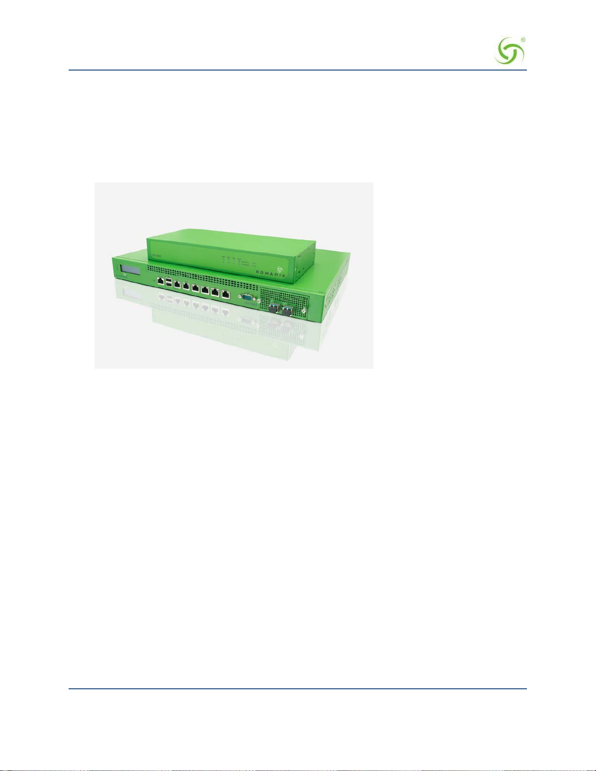
The Access Gateway is a 1U high, free-standing or rack-mountable device that provides Ethernet ports to
interface with the router and the aggregation equipment within the network. It also provides an RS232 serial
port for connecting to a Propert y Management System (PMS), while maintaining one billing relationship with
their chosen provider.
The Access Gateway enables a wide variety of network deployment options for different venue types. For
example:
• Allows for flexible WAN Connectivity (T1/E1, Cable, xDSL, and ISDN).
• Supports 802.11a/b/g and hybrid networks utilizing wired Ethernet.
• Supports key requirements needed to be compliant with the Wi-Fi ZONE™ program.
• Allows you to segment your existing ne twork into public and private sections using VLANs, then
leverage your existing network investment to create new revenue streams.
• Enables you to provide Wi-Fi access as a billable service or as an amenity to augment the main line
of business for your venue.
• Contains an advanced XML interface for accepting and processing XML commands, allowing the
implementation of a variety of service plans and offerings.
• Offers three user-friendly ways of remote management—through a Web interface, SNMP MIBs, and
Telnet interfaces—allowing for scalable, large public access deployments.
• Provides capabilities for load balancing and fail-over management across multiple ISPs.
Platform Reliability
The Access Gateway is designed as a network appliance, providing maximum uptime and reliability unlike
competitive offerings that use a server-based platform.
Local Content and Services
The Access Gateway’s Portal Page feature intercepts the user’s browser settings and directs them to a
designated Web site to securely sign up for service or log in if they have a pre- existing account.
• Allows the provider to present their customers with local services or have the user sign up for service
at zero expense.
• Offers both pre and post authentication redirects of the user’s browser, providing maximum
flexibility in service branding.
Transparent Connectivity
Resolving configuration conflicts is difficult and time consuming for network users who are constantly on the
move, and costly to the solution provider. In fact, most users are reluctant to make changes to their computer’s
network settings and won’t even bother. This fact alone has prevented the widespread deployment of
broadband network services.
Our patented Dynamic Address Translation™ (DAT) functionality offers a true “plug and play” solution by
enabling a seamless and transparent experience and the tools to acquire new customers on-site.
DAT greatly reduces provisioning and technical support costs and enables providers to deliver an easy to use,
customer-friendly service.
Introduction 4

ACCESS GATEWAY
Billing Enablement
The Access Gateway supports billing plans usi ng PayPal, scratch cards, or monthly subscriptions, or direct
billing to a hotel’s Property Management System (PMS) and can base the billable event on a number of
different parameters such as time, volume, IP address type, or bandwidth.
Access Control and Authentication
The Access Gateway ensures that all traffic to the Internet is blocked until authentication has been completed,
creating an additional level of security in the network. Also, the Access Gateway allows service providers to
create their own unique “walled garden,” enabling users to access only certain predetermined Web sites before
they have been authenticated.
Nomadix simultaneously supports the secure browser-based Universal Access Method (UAM), IEEE 802.1x,
and Smart Client s for companies such as Adjungo Networks, Boingo Wireless, GRIC and i Pass. MAC-based
authentication is also available.
Security
The patented iNAT™ (Intelligent Network Address Translation) feature creates an intelligent mapping of IP
Addresses and their associated VPN tunnels—by far the most reliable multi- session VPN passthrough to be
tested against diverse VPN termination servers from companies such as Cisco, Checkpoint, Nortel and
Microsoft. Nomadix’ iNAT feature allows multiple tunnels to be established to the same VPN server, creating
a seamless connection for all users on the network.
The Access Gateway provides fine-grain management of DoS (Denial of Service) attacks through its Ses s ion
Rate Limiting (SRL) feature, and MAC filtering for improved network reliability.
5-Step Service Branding
A network enabled with the Nomadix Access Gateway offers a 5-Step service branding methodology for
service providers and their partners, comprising:
Introduction 5

ACCESS GATEWAY
1.
Initial Fla s h Page branding.
2.
Initial Portal Page Redirect (Pr e -Authentication). Typically, this is used to redirect the user to a venuespecific Welcome and Login page.
3.
Home Page Redirect (Post-Authentication). This redirect page can be tailored to the individual user (as
part of the RADIUS Reply message, the URL is received by the NSE) or set to re-display itself at freely
configurable intervals.
4.
The Information and Control Console (ICC) contains multiple opportunities for an operator to display its
branding or the branding of partners during the user’s session. As an alternative to the ICC, a simple popup window provides the opportunity to display a single logo.
5.
The “Goodbye” page is a post-session page that can be defined either as a RADIUS VSA or be driven by
the Internal Web Server (IWS) in the NSE. Using the IWS option means that this functionality is also
available for other post-paid billing mechanisms (for example, post-paid PMS).
Introduction 6

ACCESS GATEWAY
NSE Core Functionality
Powering Nomadix’ family of Access Gateways, the Nomadix Service Engine (NSE) delivers a full range of
features needed to successfully deploy public access networks. These “core” features solve issues of
connectivity, security, billing, and roaming in a Wi-Fi public access network.
The NSE’s core package of features includes:
Access Control
Bandwidth Management
Billing Record s Mirroring
Bridge Mode
Class-Based Queuei ng
Command Line In t erface
Dynamic Address Translation™
Dynamic Transparent Proxy
End User Licensee Co unt
External Web Server Mode
Facebook Authentication
Home Page Redirect
iNAT™
Information and Control Console
Internal Web Server
International Language Support
IP Upsell
IPv6 Device Management
Link Aggregation Control Protocol (LACP)
Logout Pop-Up Window
MAC Filtering
Multi-Level Administration Support
Multi-WAN Interface Management
NTP Support
PayPal
Portal Page Redirect
RADIUS Client
RADIUS-driven Auto Configuration
RADIUS Proxy
Realm-Based Routing
Remember Me and RADIUS Re-Authentication
Introduction 7

ACCESS GATEWAY
You can set default maximum up and down bandwidths for subscribers who do
Secure Management
Secure Socket Layer (SSL)
Secure XML API
Session Rate Limiting (SRL)
Session Termination Redirect
Smart Client Support
SNMP Nomadix Private MIB
Static Port Mapping
Tri-Mode Authentication
URL Filtering
Walled Garden
Web Management Interface
Weighted Fair Queueing
Access Control
For IP-based access control, the NSE incorporates a master access control list that checks the source (IP
address) of administrator logins. A login is permitted only if a match is made with the master list contained
within the NSE. If a match is not made, the login is denied, even if a correct login name and password are
supplied.
The access control list supports up to 50 (fifty) entries in the form of a specific IP address or range of IP
addresses.
The NSE also offers access control based on the interface being used. This feature allows administrators to
block access from Telnet, Web Management, and FTP sources.
Administration can now be performed after unblocking the interfaces for the Subscriber side of the NSE. The
Administrative ports are configurable as well. See Establishing Secure Administration {Acce ss Control},
page 75.
Bandwidth Management
The NSE optimizes bandwidth by limiting bandwidth usage symmetrically or asymmetr ic a lly on a per device
(MAC address / U ser) basis, and manages the WAN Link tra ffic to provide complete bandwidth management
over the entire network. You can ensure that every user has a quality experience by placing a bandwidth
ceiling on each device accessing the network, so every user gets a fair share of the available bandwidth.
With the Nomadix ICC feature enabled, subscribers can increase or decrease their own bandwidth and pricing
plans for their service dynamically.
not have a sp ecified bandwidth setting. See Setting Up Bandwidth
Management {Bandwidth Management} on page 80.
Introduction 8

ACCESS GATEWAY
Information and Control Console (ICC)
Billing Records Mirroring
NSE-powered devices can send copies of billing records to external servers that have been previously defined
by system administrators. The NSE assumes control of billing transmissions and the saving of billing records.
By effectively “mirroring” the billing data, the NSE can send copies of billing records to predefined “carbon
copy” servers. Additionally, if the primary and secondary servers are not responding, the NSE can store up to
2,000 bil l ing records. The N S E regularly attempts to connect with the primary and secondary severs. When a
connectio n is re-established (with either server), the NSE sends the cached information to the server.
Customers can be confident that their billing information is secure and that no transaction records are lost.
Bridge Mode
This feature allows complete and unconditional access to devices. When Bridge Mode is enabled, your NSEpowered product is effectively transparent to the network in which it is located.
The NSE forwards any and all packets (except those addressed to the NSE network interface). The packets are
unmodified and can be forwarded in both directions. The Bridge Mode function is a very useful feature when
troubleshooting your entire ne twork as it allows administrators to effectively “remove” your product from the
network without physically disconnecting the unit.
Class-Based Queueing
The Nomadix Class-Based Queueing feature provides the ability to define multiple groups (classes) of users.
You can prioritize groups and guarant ee minimum band width on a per- group basis.
Users are added to classes, and rules are applied across the entire class. Each class has three configurable
attributes:
Priority
Minimum Bandwidth
Maximum Bandwidth
Class-based queueing does not apply rules to individual users. You may use bandwidth limits to restrict
individual users, if desired.
Class-based queueing does not provide application-level (layer 7) throttling or class of service.
Use Case: Property has 100 Mbps WAN Link
In this scenario, a property wishes to provide guaranteed minimum bandwidth and prioritize traffic across
three groups: Conference, Guest Room, and Public Areas. The property can configure class-based queuing
according to the following table.
Introduction 9

ACCESS GATEWAY
User Bandwidth Limit is not an attribute of Class Based Queueing, but can be
Class Priority Minimum Maximum User Bandwidth Limit**
Conference
Guest Room
Public
1
30 Mbps 100 Mbps 5 Mbps
2
3
50 Mbps 100 Mbps 5 Mbps
20 Mbps 100 Mbps 3 Mbps
applied (if desired) using exist ing Bandwidth Limit functionality.
The sum of minimums across all classes should not exceed the total available bandwidth.
It is generally recommended to set the Maximum to equal the total available bandwidth across all classes. This
allows all classes to take advantage of the full bandwidth when there is no contention.
With the above configuration, each of the three classes may utilize the entire available bandwidth when there
is no content ion. But whenever contention occurs, bandwidth will be allocated according to priority and
minimum guara nt ee .
For example, if there are no users in the Conference Class, then the Guest Room and Public Classes can use
100% of the bandwidth. If there is contention between the two, then the Guest Room class will be allocated up
to 80Mbps (because it has a higher priority), with 20Mbps taken by the Public class (its minimum guarantee).
If, however, there were no users in the Public class, then the Guest Room class could take 100% of the
bandwidth (100Mbps).
If users are introduced into the Conference class (Priority 1), and this creates contention, then they will take
bandwidth away from each of the other two classes until each reaches its minimum.
Example Illustration of Class-Based Queueing
The following diagram demonstrates the effect of Class Based Queueing with a saturated link of 200Mbps,
and three classes defined with minimum guarantees of 100Mbps (Meeting Room), 60Mpbs (VIP Guests), and
40Mbps (Lobby).
Note the following over time:
When only Lobby class subscribers are on the network, all available bandwidth is allocated to Lobby
class subscribe rs.
As VIP Guests join the network, b andwidth is allocated from Lobby class to VIP Guests, until t he
Lobby bandwidth drops to its minimum guarantee of 40Mbps.
As Meeting Room subscribers join the network, the Lobby bandwidth is already at its minimum
guarantee. Bandwidth is allocated from VIP Guests to Meeting Room subscribers, until bandwidth
for VIP Guests reaches the minimum guarantee of 60Mbps and Meeting Room reaches its minimum
guarantee of 100Mbps.
Introduction 10

ACCESS GATEWAY
Example Illustration of Weighted Fair Queueing and Class-Based Queueing
This example demonstrates the effects of using Weighted Fair Queueing and Class-Based Queueing together.
In this example configuration, these parameters apply:
A single WAN interface with a globa l up per limit of 900M
600 total subscribers; 200 with upper bandwidth of 2M, 200 with upper bandwidth of 4M, 200 with
upper bandwidth of 6M
Two classes:
Class1: Priority 1, Minimum = 400M, Maximum = 900M
Class2: Priority 2, Minimum = 200M, Maximum = 900M
100 subscribers with each limit are assigned to Class1, and 100 to Class2
Class2 subscribers begin running first, followed by those in Class1 about a minute later.
The subscribers in Class2 initially receive all of the available bandwidth, weighted correctly. As Class1
subscribers connect, the Class2 subscribers are driven to the minimum of 200M, still weighted correctly. At
that point the Class1 subscribers receive all remaining bandwidth (about 700M), also weighted correctly.
Introduction 11

ACCESS GATEWAY
Notes and Cautions
Exercise caution in mixing subscribers with and without class membership. Subscribers with no class
membership are automatically assigned a priority of eight the lowest priority and have no minimum
bandwidth.
If higher priority classes are not assigned a maximum bandwidth cap, it is possible that unassigned subscribers
will be completely starved for bandwidth.
In a mixed user environment, care should be taken to ensure top priority classes have sensible maximum
thresholds. To take advantage of the class bandwidth queuing one should assign subscribers to a minimum
bandwidth and specific class.
When running Class-Based Que ueing concurrently with Weighted F air Queueing, the N SE will maintain the
weighting when multiple WAN interfaces with Load Balancing are configured. The upper bandwidth limit is
constrained by the maximum b a ndwidth that the platform will support.
See also Class-Based Queueing on page 84.
Command Line Interface
The Command Line Interface (CLI) is a character-based user interface that can be accessed remotely or via a
direct cable connection. Unt il your Nomadix product is up and running on the network, the CLI is the
Network Administrator’s window to the system. Software upgrades can only be performed from the CLI.
See also The Management Interfaces (CLI and Web) on page 47.
Daylight Savings Time and IANA Time Zone Support
Time configuration includes s up port for configuration by region/city, automatic daylight savings time
adjustment, and official IANA (iana.org) time zones.
Introduction 12

ACCESS GATEWAY
Dynamic Address Translation™
Dynamic Address Translation (DAT) enables transparent broadband network connectivity, covering all types
of IP configurations (static IP, D HCP, DNS), regardless of the platform or the operating system used—
ensuring that everyone gets access to the network without the need for changes to their computer’s
configuration settings or client-side software. The NSE supports both PPTP and IPSec VPNs in a manner that
is transparent to the user and that provides a more secure standard connection. See also Transparent
Connectivity on page 4.
Dynamic Transparent Proxy
The NSE directs all HTTP and HTTPS proxy requests through an internal proxy which is transparent to
subscribers (no need for users to perform any reconfiguration tasks). Uniquely, the NSE also supports clients
that dynamically change their browser status from non-proxy to proxy, or vice versa. In addition, the NSE
supports proxy ports 80, 800-900, 911 and 990 as well as all unassigned ports (for example, ports above
1024), thus ensuring far fewer proxy related support calls than competitive products.
End User Licensee Count
The NSE supports a range of simultaneous user counts depending on the Nomadix Access Gateway you
choose. In addition, depending on your platform, various user count upgrades are available for each of our
NSE-powered products that allow you to increase the simultaneous user count.
External Web Server Mode
The External Web Server (EWS) interface is for customers who want to develop and use their own content. It
allows you to create a “richer” environment than is possible with your product’s embedded Internal Web
Server.
The advantages of using an External Web Server are:
Manage frequently changing content from one lo cation.
Serve different pages depend ing on site, sub-location (for example, VLAN), and user.
Take advantage of the comprehensive Nomadix XML API to implement more complex billing plans.
Recycle existing Web page content for the centrally hosted portal page.
If you choose to use the EWS interface, Nomadix Technical Support can provide you with sample scripts. See
also Contact Information on page 268.
Facebook Authentication
You may provide Facebook authentication for facility guests. Login with Facebook is a 2-step process. A user
must first click the New User button on the Nomadix splash screen:
Introduction 13

ACCESS GATEWAY
Then the user must click the “Log in with Facebook” button:
Several configuration steps are required to support Facebook authentication. See the following sections for
specific instructions:
Defining the AAA Services {AAA} on page 68
Assigning Passthrough Addresses {Passthrough Addresses} on page 112
Defining the Billing Options {Billi ng Options} on page 170
Adding and Updating Port-Location Assignments {Add} on page 151
Home Page Redirect
The NSE supports a comprehensive HTTP redirect logic that allows network administrators to define multiple
instances to intercept the browser’s request and replace it with freely configurable URLs.
Portal page redirect enables redirection to a portal page
before the authentication process. This means that
anyone will get redirected to a Web page to establish an account, select a service plan, and pay for access.
Home Page redirect enables redirection to a page
after the authentication process (for example, to welcome a
specific user to the service—after the user has been identified by the authentication process. See also Portal
Page Redirect on page 18.
iNAT™
Nomadix invent ed a new way of intelligently supporting multiple VPN connections to the same termination at
the same time (iNAT™), thus solving a key problem of many public access networks.
Introduction 14

ACCESS GATEWAY
Nomadix’ patented iNAT™ (intelligent Network Address Translation) feature contains an advanced, real-time
translation engine that analyzes all data packets being communicated between the private address realm and
the public address realm.
The NSE performs a defined mode of network address translation based on packet type and protocol (for
example, ISAKMP, etc.). UDP packet fragmentation is supported to provide more seamless translation engine
for certificate-based VPN connections.
If address translation is needed to ensure the success of a specific application (for example, multiple users
trying to access the same VPN termination server at the same time), the packet engine selects an IP address
from a freely definable pool of publicly routable IP addresses. The same public IP address can be used as a
source IP to support concurrent tunnels to different terminati on devices—offering unmatched efficiency in the
utilization of costly public IP addresses. If the protocol type can be supported without the use of a public IP
(for example, HTTP, FTP), our proven Dynamic Address Translation™ functionality continues to be used.
Some of the benefits of iNAT™ include :
Improves the success rate of VPN connectivity by misconfigured users, thus reducing customer
support costs and boosting customer satisfaction.
Maintains the security benefits of traditional address translation tech nologies while enabling
secure VPN connections for mobile workers accessing corporate resources from a public access
location.
Dynamically adjusts the mode of address translation during the user's se ssion, depending on
the packet type.
Supports users with static private IP addresses (for example, 192.168.x.x) or public
(different subnet) IP addresses without any changes to the client IP settings.
Dramatically heightens the reusability factor of costly public IP addresses.
Information and Control Console
The Nomadix ICC is a HTML-based pop-up window that is presented to subscribers with t heir Web
browser. The ICC allows subscribers to select their bandwidth and billing options quickl y and
efficiently from a simple pull-down menu. For PayPal accounts, the ICC displays a dynamic “time”
field to inform subscribers o f the time remaining on their account.
Information and Control Console (ICC)
Additionally, the ICC contains multiple opportunities for an operator to display its branding or the
branding of partners during the user’s session, as well as display advertising banners and present a
choice of redirection options to their subscribers.
See also:
5-Step Service Branding
Logout Pop-Up Window
Information and Control Console
Introduction 15

ACCESS GATEWAY
Initial NSE Configuration
See Installing the Access Gateway on page 35 for initial installation and configuration instr uctio ns.
Internal Web Server
The NSE offers an embedded Internal Web Server (IWS) to deliver Web pages stored in flash
memory. These Web pages are configurable by the system administrator by selecting various
parameters to be displayed on the internal pages. When providers or HotSpot owners do not want to
develop their own content, the IWS is the answer. A banner at the top of each IWS page is
configurable and contains the customer's company logo or any other image fi l e they desire.
To support PDAs and other hand-held devices, the NSE automatically formats the IWS pages to a
screen size that is optimal for the particular device being used.
See also:
5-Step Service Branding
International Language Support
International Language Support
The NSE allows you to define the text displayed to your users by the IWS without any HTML or
ASP knowledge. The language you select determines the language encoding that the IWS instructs
the browser to use.
The available language options are:
English
Chinese (Big 5)
French
German
Japanese (Shift_JIS)
Spanish
For localizing the user-facing text into other languages, the following character sets are supported:
Western ISO-8859-1
Chinese (Big5, EUC-CN, EUC-TW, GB2312)
Japanese (EUC-JP, ISO-2022-JP, Shift_JIS)
Korean (EUC-KR, ISO-2022-KR, KS_C_5601)
UTF-8
See Defining Languages {Language Support} on page 179 for language configuration information.
You also can change the language of the Web Management Interface text. See Selecting the
language of the Web Management Interface, page 64. English and Chinese (simplified) interfaces
are supported.
IP Upsell
System administrators can set two different DHCP pools for the same physical LAN. When DHCP
subscribers select a service plan with a public pool address, the NSE associates their MAC address
with their public IP address for the duration of the service level agreement. The opposite is true if
they select a plan with a private pool address. This feature enables a competitive solution and is an
instant revenue generator fo r ISPs.
Introduction 16

ACCESS GATEWAY
The IP Upsell feature solves a number of connectivity problems, especially with regard to certain
video conferencing and online gaming applicat ions.
You have additional flexibility for configuring up sell scenarios. Users can be assigned WAN’s of
different bandwidth capabilities; for e xample, hotel guests with loyalty memberships can q ua lif y fo r
premium services.
IPv6 Device Management
There are many network management tools that have IPv6 support. They can communicate to the
network devices and servers over IPv4 or IPv6 transport. They can also perform communications to
those devices and servers utilizing t he IPv6 interface for configuration, performance and status. The ability to
manage infrastructure devices that are addressed with IPv6 addresses behind the Gateway is built in.
Link Aggregation Control Protocol (LACP)
Link Aggregati o n Control Protocol is a useful feature for creating dyna mi c port groupings or Aggregate
Groups. LACP allows for the combing (aggregation) of multiple network connections in parallel in order to
increase throughput beyond what a single connection could sustain, and to provide redundancy in case one of
the links should fail. A Link Aggregation Group (LAG) must be configured to combine a number of physical
ports together to make a single logical interface. The network must be configured and support active LACP.
Link Aggregation will not allow throughput beyond the device supported throughput.
Logout Pop-Up Window
As an alternative to the ICC, the NSE delivers a HTML-based pop-up window with the following
functions:
Provides the opportunity to display a single logo.
Displays the session’s elapsed/count -down time.
Presents an explicit Logout button.
See also Information and Control Console on page 15.
MAC Filtering
MAC Filtering enhances Nomadix' access control technology by allowing system administrators to
block malicious users based on their MAC address. Up to 50 MAC addresses can be blocked at any
one time. See also Session Rate Limiting (SRL) on page 20.
Multi-Level Administration Support
The NSE allows you to define 2 concurrent access levels to differentiate between managers and
operators, where managers are permitted read/write access and operators are restricted to read access
only.
Once the logins have been assigned, managers have the ability to perform all write commands
(Submit, Reset, Reboot, Add, Delete, etc.), but operators cannot change any system settings. When
Administration Concurrency is enabled, one manager and three operators can access the Access
Gateway platform at any one time.
Multi-WAN Interface Management
The NSE supports multiple independently configurable WAN interfaces, to optimize ISP resource
allocation, and provide load balancing (optional), fail-over and upsell capabilities.
Introduction 17

ACCESS GATEWAY
NTP Support
The NSE supports Network Time Protocol (NTP), an Internet standard protocol that assures
accurate synchronization (to the millisecond) of computer clock times in a network of computers.
NTP synchronizes the client’s clock to the U.S. Naval Observatory master clocks. Running as a
continuous background client program on a computer, NTP sends periodic time requests to servers,
obtaining se rver time stamps and using them to ad just the client's cl ock.
PayPal
PayPal support allows the internet ac c e ss to be billed to either a PayPal account or directly to a
credit card held by the end user.
Portal Page Redirect
The NSE contains a comprehensive HTTP page redirection logic that allows for a page redirect
before (Portal Page Redirect) and/or after the authentication process (Home Page Redirect). As part
of the Portal Page Redirect feature, the NSE can send a defined set of parameters to the portal page
redirection logic that allows an Exter nal Web Server to perform a redirection based on:
Access Gateway ID and IP Address
Origin Serve r
Port Location
Subscriber MAC address
Externally hosted RADIUS lo gin failure page
This means that the network administrator can now perform location-specific service branding (for
example, an airport lounge) from a centralized Webserver.
See also Adding and Updating Port-Location Assignments {Add} on page 151.
RADIUS-driven Auto Configuration
Nomadix’ unique RADIUS-driven Auto Configuration functionality util izes the existing
infrastructure of a mobile operator to provide an effortless and rapid method for configuring devices
for fast network roll-outs. Once configured, this methodology can also be effectively used to
centrally manage configuration profiles for all Nomadix devices in the public access network.
Two subsequent events drive the automatic configuration of Nomadix devices:
1.
A flow of RADIUS Authentication Request and Reply messages between the Nomadix gateway
and the centralized RADIUS server that specifies the location of the meta configuration file
(containing a listing of the individual configuration files and their download fr equency status)
are downloaded from an FTP server into the flash of the Nomadix device.
2.
Defines the automated login into the centralized FTP server and the actual download process
into the flash.
Optionally, the RADIUS authentication process and FTP download can be secured by sending the
traffic through a peer-to-peer IPSec tunnel established by the Nomadix gateway and terminated at
the NOC (Network Operations Center). See also Secure Management on page 19.
RADIUS Client
Nomadix offers an integrated RADIUS (Remote Authentication Dial-In User Service) client with
the NSE allowing service providers to track or bill users based on the number of connections,
location of the connection, bytes sent and received, connect time, etc. The customer database can
exist in a central RADIUS server, along with associated attributes for each user. When a customer
connects into the network, the RADIUS client authenticates the customer with the RADIUS server,
Introduction 18

ACCESS GATEWAY
applies associated attributes st ored in that customer's profile, and logs their activity (including bytes
transferred, connect time, etc.). The NSE's RADIUS implementation also handles vendor specific
attributes (VSAs), required by WISPs that want to enable more advanced services and billing
schemes, such as a per device/per month connectivity fee.
RADIUS Proxy
The RADIUS Proxy feature relays authentication and accounting packets between the parties
performing the authentication process. Different realms can be set up to directly channel RADIUS
messages to the various RADIUS servers. This functionality can be effectively deployed to:
Support a wholesale WISP model directly from the edge without the need for any
centralized AAA proxyinfrastructure.
Support EAP authenticators (for example, WLAN APs) on the subscriber-side of the NSE
to transparently proxy all EAP types (TLS, SIM, etc.) and to allow for the distribution of
per-session keys to EAP authenticators and supplic ants.
Realm-Based Routing
Realm-Based Routing provides advanced NAI (Network Access Identifier) routing capabilities, enabling
multiple service providers to share a HotSpot location, further supporting a Wi-Fi wholesale model. This
functionality allows users to interact only with their chosen pr ovider in a seamless a nd transparent manner.
The Access Gateway can route RADIUS messages depending on the Network Access Identifier (NAI). Both
prefix-based (for example, ISP/username@ISP.net) and suffix-based (username@ISP.net) NAI routing
mechanisms are supported. Together, the RADIUS Proxy and Realm-Based Routing further support the
deployment of the Wholesale Wi-Fi™ model allowing multiple providers to service one location.
Remember Me and RADIUS Re-Authentication
The NSE’s Internal Web Server (IWS) stores encrypted login cookies in the browser to remember logins,
using usernames and passwords. This “Remember Me” functionality creates a more efficient and better user
experience in wireless networks.
RADIUS Re-Authentication allows the Access Gateway to store the RADIUS credentials of specific devices
for a configurable period of time. This helps devices to seamlessly leave and then reconnect to the guest
network and retain their RADIUS parameters without requiring another manual logi n. See also Defining the
RADIUS Client Settings {RAD IUS Client} on page 124.
Secure Management
There are many different ways to configure, manage and monitor the performance and up-time of network
devices. SNMP, Telnet, HTTP and ICMP are all common protocols to accomplish network management
objectives. And within those objectives is the requirement to provide the highest level of security possible.
While several network protocols have evolved that offer some level of security and data encryption, the
preferred method for attaining maximum security across all network devices is to establish an IPSec tunnel
between the NOC (Network Operations Center) and the edge device (early VPN protocols such as PPTP have
been widely discredited as a secure tunneling method).
As part of Nomadix’ commitment to provide outstanding carrier-class network manageme nt capabilities to its
family of public access gateways, we offer secure management through the NSE’s standards-driven, peer-topeer IPSec tunneling with strong data encryption. Establishing the IPSec tunnel not only allows for the secure
management of the Nomadix gateway using any preferred management protocol, but also the secure
management of third party devices (for example, WLAN Access Points and 802.3 switches) on private
subnets on the subscriber side of the Nomadix gateway. See also D e fining IPSec Tunnel Settings {IPSec} on
page 102.
Introduction 19

ACCESS GATEWAY
f you plan to implement XML for external billing, please contact technical
Two subsequent events drive the secure management function of the Nomadix gateway and the devices
behind it:
1.
Establishing an IPSec tunnel to a centralized IPSec termination server (for example, Nortel Contivity). As
part of the session establishment process, key tunnel parameters are exchanged (for example, Hash
Algorithm, Security Association Lifetimes, etc.).
2.
The exchange of management traffic, originating either at the NOC or from the edge device through the
IPSec tunnel. Alternatively, AAA data such as RADIUS Authentication and Accounting traffic can be
sent throu gh the IPSec tunnel. See also RAD IUS Client on page 18.
The advantage of using IPSec is that all types of management traffic are supported, including the following
typical examples:
ICMP - PING from NOC to edge devices
Telnet - Telnet from NOC to edge devices
Web Management - HTTP access from NOC to edge devices
SNMP
SNMP GET from NOC to subscriber-side device (for example, AP)
SNMP SET from NOC to subscriber-side device (for example, AP)
SNMP Trap from subscriber-side device (for example, AP) to NOC
Secure Socket Layer (SSL)
This feature allows for the creation of an end-to-end encrypted link between your NSE- powered product and
wireless clients by enabling the Internal Web Server (IWS) to display pages under a secure link—important
when transmi tting AAA information in a wireless network when using RADIUS.
SSL requires service providers to obtain digital certificates to create HTTPS pages. Instructions for obtaining
certificates are provided by Nomadix.
Secure XML API
XML (Extensible Markup Language) is used by the subscriber management module for user administration.
The XML interface allows the NSE to accept and process XML commands from an external source. XML
commands are sent over the ne twork to your NSE-powered product which executes the commands, and
returns data to the system that initiated the command request. XML enables solution provi ders to customize
and enhance their product installations.
This feature allows the operator to use Nomadix' popular XML API using the built-in SSL certificate
functionality in the NSE so that parameters passed between the Gateway and the centralized Web server are
secured via SSL.
support for the XML specification of your product. Refer to Contact
Information on page 268.
Session Rate Limiting (SRL)
Session Rate Limiting (SRL) signific a ntly reduces the risk of “Denial of Service” attacks by allowing
administrators to limit the number sessions any one user can take over a given time period and, if necessary,
then block malic io us use r s.
Introduction 20

ACCESS GATEWAY
Session Termination Redirect
Once connected to the public access network, the NSE will automatically redirect the customer to a Web site
for local or personalized services if the customer logs out or the customer’s account expires while online and
the goodbye page is enabled. In addition, the NSE also provides pre- and post-authentication redirects as well
as one at session termination.
Smart Client Support
The NSE supports authentication mechanisms us ed by Smart Clien ts by companies such as Adjungo
Networks, Boi ngo Wireless, GRIC and iPass.
SNMP Nomadix Private MIB
Nomadix’ Access Gateways can be easily managed over the Internet with an SNMP client manager (for
example, HP OpenView or Castle Rock). See Using an SNMP Manager on page 65.
To take advantage of the functionality provided with Nomadix’ private MIB (Management Information Base),
to view and manage SNMP objects on your product, see Installing the Nomadix Private MIB on p age 62.
Static Port Mapping
This feature allows the network administrator to setup a port mapping scheme that forwards packets received
on a specific port to a particular static IP (typically private and misconfigured) and port number on the
subscriber side of the NSE. The advantage for the network administrator is that free private IP addresses can
be used to manage devices (such as Access Points) on the subscriber side of the NSE without setting them up
with Public IP addresses.
Tri-Mode Authentication
The NSE enables multiple authentic a tion models providing the maximum amount of flexibility to the end user
and to the operator by supporting any type of client entering their network and any type of business
relationship on the back end. For example, in addition to supporting the secure browser-based Universal
Access Method (UAM) via SSL, Nomadix is the only company to simultaneously support port-based
authentication using IEEE 802.1x and authent ication mechanisms used by Smart Clients. MAC-based
authentication is also available.
See also:
Access Control and Authentic ation
Smart Client Support
URL Filtering
The NSE can restrict access to specified Web sites based on URLs defined by the system administrator. URL
filtering will block access to a list of site s and/or domains entered by the administrator using the following
three methods:
Host IP address (for example, 1.2.3.4).
Host DNS name (for example, www.yahoo.com).
DNS domain name (for example, *.yahoo.com, meaning all sites under the yahoo.com hierarchy,
such as finance.yahoo.com, sports.yahoo.com, etc.).
The system administrator can dynamically add or remove up to 300 specific IP addresses and domain names
to be filtered for each property.
Introduction 21

ACCESS GATEWAY
Walled Garden
The NSE provides up to 300 IP passthrough addresses (and/or DNS entries), allowing you to create a “Walled
Garden” within the Internet where unauthenticated users can be granted or denied access to sites of your
choosing.
Web Management Interface
Nomadix’ Access Gateways can be managed remotely via the built-in Web Management Interface where
various levels of administration can be established. See also Using the Web Management Interface (WMI)
on page 64.
Weighted Fair Queueing
Weighted Fair Queueing alloca te s bandwidth to individual users or groups in proportion to their individual or
group bandwidth limits. Weighted Fair Queueing provides a fall-back in an over-subscribed scenario.
Example Scenario
Your facility has a 150 Mbps internet connection. You have 100 subscribers with a basic plan with 1M
up/down bandwidth limits, and 100 subscribers with a premium plan with 2M up/ down speeds
At full capacity, your 200 subscribers will consume 300 Mbps. However, the total available bandwidth is only
150 Mbps.
When WFQ is ON, the premium subscribers will get a total bandwidth of 100 MB. And regular subscribers
will get a total bandwidth of 50MB only. The ratio of bandwidth utilization between the premium subscribers
and regular subscribers remains 2:1.
Introduction 22

ACCESS GATEWAY
Load Balancing requires an optional NSE product license.
Optional NSE Modules
Load Balancing
With the Load Balancing Module, Internet traffic is balanced across multiple WAN/ISP connections to ensure
that traffic is distributed based on the capability of each connection. For example, organizations may wish to
balance traffic between a low-cost DSL WAN/ISP and one high-performance, high-capacity WAN/ISP. This
is of value when multiple links are used to optimize cost for Internet service, such as balancing traffic between
one low-cost DSL WAN/ ISP and one high-performance, high-capacity WAN/ISP. Hotels may also use this
capability to provide tiered services reflecting the capacity of the WAN/ISP connection.
The Link Failover feature of the Load Balancing Module is designed to improve business c ontinuity. In the
event that one or more links fail, traffic is seamlessly rerouted to the remaining surviving links without lapse
of service. When the failed links recover, the NSE routes new connections toward the now-working links until
a normal, balanced configuration is reached.
For details of the Load Balancing capabilities and sample use cases, see Load Balancing and Link Failover
on page 27.
Hospitality Module
The optional Hospitality Module p r ovides the widest range of Property Management System (PMS) interfaces
to enable in-room guest billing for High Speed Internet Access (HSIA) service. This module also includes 2Way PMS interface capability for in-room billing in a Wi- Fi enabled network. In ad dition, the Hospitality
Module includes the Bill Mirro r functionality for posting of billing records to multiple sources. With this
module, the NSE also supports b illing over a TCP/IP connection to select PMS interfaces.
By integrat i ng with a hotel’s PMS, your NSE-powered product can post charges for Internet access directly to
a guest’s hotel bill. In this case, the guest is billed only once. The NSE outputs a call accounting record to the
PMS system whenever a subscriber purchases Internet service and decides to post the charges to their room.
Nomadix’ Access Gateways are equipped with a serial PMS interface port to facilitate connectivit y with a
customer’s Property Management System.
Some Property Management Systems may require you to obtain a license before
integrating the PMS with the Access Gateway. Check with the PMS vendor.
High Availability Module
Your product license may not support this feature.
The optional High Availability Module offers enhanced network uptime and service availability when
delivering high-quality Wi-Fi service by providing Fail-Over functionality. This module allows a secondary
Nomadix Access Gateway to be placed in the network that can take over if the primary device fails, ensuring
Wi-Fi service remains uninterrupted.
Introduction 23

ACCESS GATEWAY
Network Architecture (Sam p le)
The Access Gateway can be deployed effectively in a variety of wireless and wired broadband environments
where there are many users—usually mobile—who need high speed access to the Internet.
The following example shows a potential Hospitality application:
Introduction 24

ACCESS GATEWAY
Multiple Unit Clusterin g
In the recent past, it was necessary to segment the network to serve a number of subscribers that exceed the
user count on a Nomadix gateway. Now with clustering all subscribers can be on the same segment, as the
subscribers are distributed acro ss multiple gateways. A large number of subscribers can be distributed to as
many as 256 gateways, thus providing a design capacity of two million subscribers.
One can scale the cluster up and down just by adding gateways or removing gateways. Remember that a
subscriber and the subscriber’s MAC address are positioned in a specific gateway, so changing the number of
gateways will require the gateways to reconfigure, and their current subscriber table updated. If a prepaid
subscriber exists in a radius o r authentication file, this prepayme nt will be lost. It is recommended that
prepayment situations should be avoided.
The cluster will distribute the subscribers MAC addresses according to a modulus calculation based on the last
three bytes of the MAC address of the subscriber. The result will determine which gateway will support that
MAC address while the other gateways ignore the traffic for the MAC.
There is currently no failover in support of clustering. The following other NSE features are not compatible
with clustering:
Proxy ARP for device
Routed subscribers
Identifying the Resident Gateway in a Cluster Environment
To diagnose device connection problems in a clus t er environment, you must identif y the resident gateway. For
a given MAC address, you can determine the gateway as follows. You will need the last three bytes of the
device MAC address and the total number of gateways.
Convert the hex bytes to decimal:
1.
Using the Windows Calculator in programmer mode
2.
In hex mode, input the last three bytes of the MAC address
3.
Convert to decimal by using that function on the calculator
The resident gateway is the (decimal bytes) modulus (the total number of gateways), plus 1.
Introduction 25

ACCESS GATEWAY
The following graphic illustrates a clustering scenario with 12,000 users and three gateways.
Introduction 26

ACCESS GATEWAY
Load Balancing and Link Failover
The NSE supports individual configuration of multiple WANs on an Access Gateway (supported on AG2400,
AG5600, AG5800, and AG5900 hardware). Hotels can use this capability in a number of ways, including load
balancing, failure protection, and subscriber allocation.
This section provides use cases and scenarios to help you consider the full advantage of these capabilities.
Definitions and Concepts
Load Balancing
Load balancing refers to the general process of balancing user traffic across multiple ISP connections. All
load-balancing appliances, as well as the Nomadix NSE, support load balancing.
Link Aggregation
Link aggregation refers to the process of connect ing multiple ISP connections to an appliance and having the
sum of all of the ISP bandwidth available to be shared across all users.
However, one individual connec tion is limited to the speed of the ISP connection that is curre ntly being used.
For example, a hotel may aggregate 5 x 1.5Mbps DSL connections together. This means that a total of
7.5Mbps of bandwidth is available to be shared across all users, but a single user can receive a maximum of
1.5Mbps. All load-balancing appliances, as well as the Nomadix NSE, support link aggregation. In most
cases, link aggregation and load b alancing is effectively the same thing.
Link Failover
Link failover (sometimes referred to ISP redundancy) is the process of providing a second (or occasionally a
third or more) ISP link as a back up to the primary I S P link. In the event that the primary link fails, all traffic
is re-routed to the backup link, until such time as the primary link becomes available.
Combined Load Balancing and Link Failover
This is the process where both load balancing and link failover are combined together. It represents the best of
both worlds. Where multiple ISP links are used in load balancing mode, in the event that one or more links
fail, all traffic is automatically re routed to the remaining surviving links. When the failed links r e cover, new
connections are routed toward these until the normal balanced configuration is reached.
ISP link Selection Criteria
In a load-balancing scenario, some criteria must be used to decide which ISP is selected for outgoing traffic.
There a number of factors that influence this decision, including:
Identity of the users: Is a random ISP section used or is it desirable to have certain users steered
toward a particular ISP?
For random ISP: Whether subscriber, destination address or session-based link selection is used?
User-Based ISP Selection versus Random ISP Selection
User-based ISP selection is the process whereby the ISP link that is selected in a load-balanced environment is
based on the identity of the user. For example, all users from guest rooms may be steered toward one ISP link,
and all meeting room users steered toward another ISP link that is only used for meetings and conferences.
The alternative is to use random ISP selection, whereby the load balancer or NSE selects the ISP to be used
according to the current load conditions. The Nomadix NSE uses random ISP selection by default.
Introduction 27

ACCESS GATEWAY
Link Availability Detection Me thod and Time
Load balancing and failover requires some form of monitoring of each ISP link to deter min e its a vailability
for executing load balancing and failover decisions. Ge nerally, link monit oring is accomplished by two
different methods:
1.
Periodic probing of predefined hosts using HTTP or ICMP ping requests.
2.
Periodic DNS queries to the DNS servers provided by each ISP.
The period between successive link tests is usually configured, and is typically set to between 30 seconds and
60 seconds. This represents the maximum time for which a user will remain connected to a failed ISP
connection before being re-routed to a working ISP link in an ISP failure scenar io.
Traffic Balancing and Weighting
Load balancers have some form of weighting of traffic between links to achieve a desired balance scenario.
With the Nomadix NSE, traffic is balanced by individual subscriber numbers, and weighted according to the
speed of the ISP connected to each port. For example, if an NSE has 2 x 10M links connected and currently
has 100 active subscribers, then 50 users would be connected to each link. If the ISP links were 10 Mbps and
40Mbps, then 20 users would be connected to the 10M link and 80 users to the 40M link, and so on.
Load Rebalancing upon Link Recovery
Load balancing and failover with well-configured link availability detection provides fast and effective
recovery from ISP link failure occurrences. Additional consideration must be made as to what actions should
be taken when a failed ISP link recovers. The Nomadix approach is to rebalance as the ISP links change, thus
making sure the maximum level of service is always provided. There is a small yet important waiti ng time to
ensure cha nging links is kept t o a minimum.
Load Balancing and Failure Considerations
1.
Is load balancing or just ISP failover required?
2.
Is aggregation of multiple low-speed links required?
3.
How reliable are different local ISP services?
4.
What are the relative costs of different ISP services?
5.
Do ISP links need to be shared between guest and back-office users?
6.
Is there a requirement to have certain users connected to a particular ISP?
1. It may be a requirement to provide just a backup service to the primary ISP service in the case that the main
HSIA ISP fails. The backup service may be on a pay-to-use basis through a 3G or 4G wireless modem, or
be a low-cost, lower-tier service, such as a cable modem service, that is only used when the main ISP link is
down, on the b asis that providing a reduced HSIA service is better than no service at all when the main ISP
link is down. Alternatively, the organization may have multiple ISP links, and wants to be a ble to fully
utilize all of them under normal conditions. The Nomadix NSE supports both failover only and combined
load balancing with failover.
2. In some instances, suitable high-speed internet services required to meet the aggregate needs of the
organization may not be available or are simply too expensive. In this case it may be desirable to aggregate
multiple lower-cost, lower-speed lines together. The Nomadix AG2400 and AG5600 can aggregate services
from up to three ISP links; the AG5800 and AG5900 can handle up to five links.
3. It is important to consider the re la tive quality of each ISP link. If a second link is much lower quali ty than
the main ISP l ink, then it shou ld only be used as a ba ck-up link in failover mode, and not in a load-balanced
environment. If the quality of the links is much the same, then load balancing with fail over should be used .
4. It is important to consider the re la tive cost of links. If all links have a fixed monthly charge, then ide ally
they should be used in a load-balanced mode, so that costly links are not sitting unused most of the time.
Introduction 28
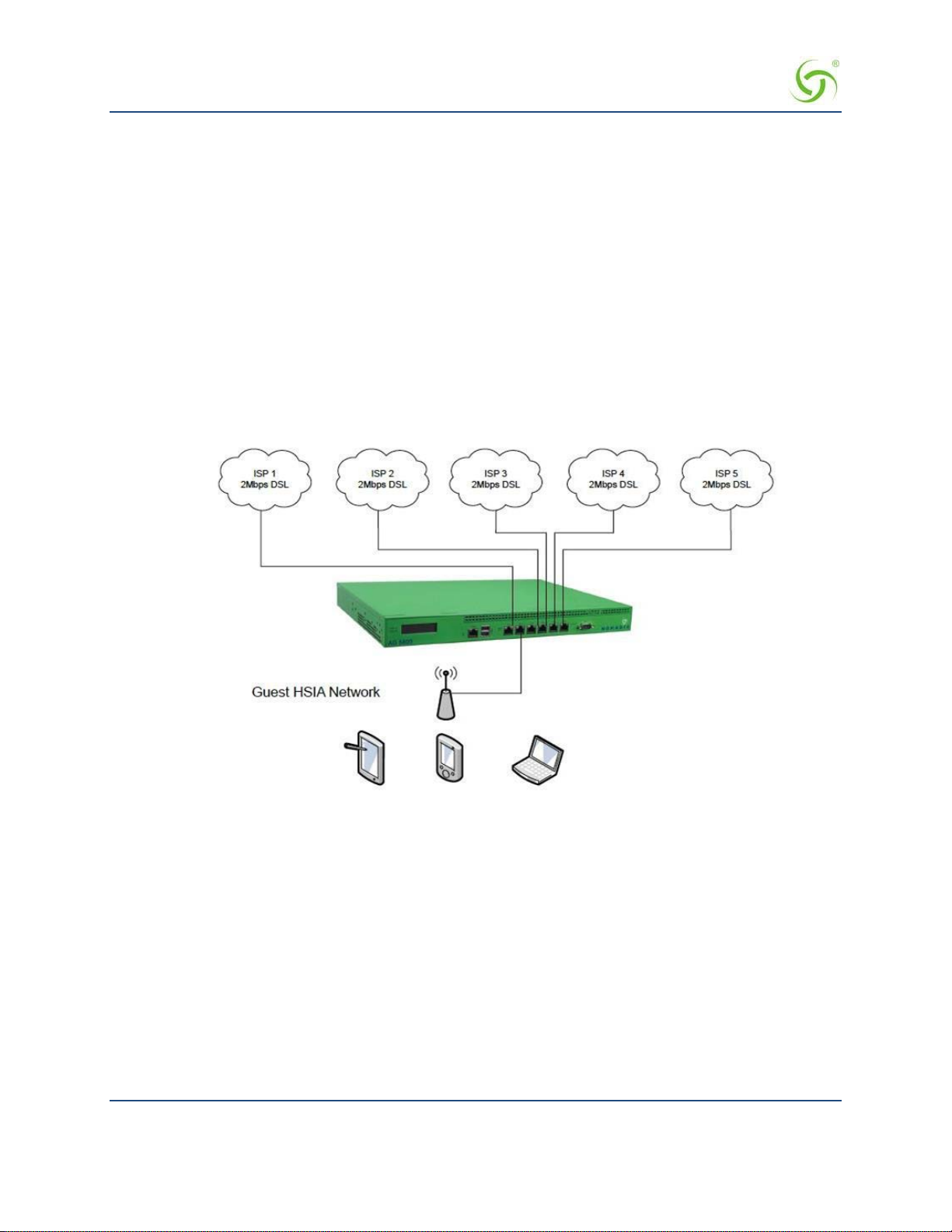
ACCESS GATEWAY
But if an ISP link has a relatively low monthly charge with high per- megabyte data usage charges, then it
should only be used in failover mode as a backup to a main ISP link.
5. It may be requirement to share ISP bandwidth between Guest HSIA and Hotel Admin networks, or have
each network available as a fall-back network for the other. Both scenarios can be handled with the
Nomadix NSE.
6. It may be desirable to have certain users connected to a particular ISP link, and other users connected to a
different ISP link. The Nomadix NSE provides a “preferred WAN” radius attribute (VSA). For example,
paying users may be connected to an expensive high-quality link, with free users connected to a lowerquality link, with link failover still available if the preferred link fails.
Some examples of typical common deployment scenarios are outlined below: These are just examples and
other deployment scenarios can be handled, as well.
Load Balancing across Multiple Low Speed Links
In this example, an establishment has access to only low-speed, DSL-based ISP circuits and wishes to
aggregate f ive such links together. The Nomadi x NSE is configured with load balanc ing between all links.
Failover to Standby ISP Link
In this example, the organization has a high-quality 100M Ethernet service. But to guarantee continuous HSIA
service, the organization has a back-up ISP service from a low-cost wireless provider, which charges on a data
volume basis. The organization only wishes for this link to be used when the main ISP ci rcuit is not available.
Introduction 29

ACCESS GATEWAY
The Nomadix NSE is configured for failover only from the WAN to port Eth2 on the NSE.
Separate Guest HSIA and Admin ISP Links, with Failover Between Each ISP Link
In this scenario, the hotel has separate HSIA and Hotel Admin ISP circuits. Under normal circumstances,
Guests will be connected to the Guest HSIA ISP, and Hotel Admin users will connect to the Admin ISP. If
either link fails, then failover to the other link will occur. If the Guest HSIA link fails, the guests will be
connected to the Admin ISP link until the Guest HSIA link is restor e d. If the Admin ISP link fails, the Admin
users will be connected to the Guest HSIA link until the Admin ISP is restored
The Nomadix NSE is configured with load balancing and failover. All Guests use ISP 1 as the preferred
WAN, the Admin network router uses ISP2 as the preferred WAN.
Introduction 30

ACCESS GATEWAY
Guest HSIA Failover Only, to Admin Network
In this scenario, the hotel has separate ISP circuits for the Guest HSIA network and Hotel Admin network.
The hotel wants the Ad min network to be available as a back-up link in case the Guest HSIA ISP link fails.
There is no back-up for the Admin ISP network.
The Nomadix NSE is configured with link failover between the WAN port and port ETH2, which is
connected to the hotel Admin network router.
Sharing Guest HSIA Network and Hotel Admin Network Among Multiple ISP Links
In this scenario, multiple ISP links ar e c onnected to the Nomadix NSE, in a similar method to the first
scenario, but both the guest HSIA network and the Hotel Admin network are connected to the NSE and share
the aggregate bandwidth of the combined ISP links.
The Nomadix NSE is configured for load balancing, and the back office router's MAC address is registered in
as a device in the NSE with an appropriate bandwidth limit.
Introduction 31

ACCESS GATEWAY
Load Balancing With Users Connected to a Preferred ISP Link
In this scenario, the hotel has purchased 2 x ISP links for guest HSIA. One is a high-quality, high-cost
"business grade" ISP circuit, and the other is a low-cost, lower-grade domestic service provided by the local
cable TV operator. The hotel has a number of bill plan options including free-to-use and pay-to-use premium
plans. Under normal circumstances, the hotel wants guests who have selected a free plan to use the low-cost
link, and guests who have selected a premium service to use the higher-cost, business-grade ISP connection. If
either link fails, guest should fail over to the other links until the preferred link is restored.
Introduction 32

ACCESS GATEWAY
Online Help (WebHelp)
The Access Gateway incorporates an online Help system called “WebHelp” which is accessible through the
Web Management Interface (when a remote Internet connection is established following a successful
installation). WebHelp is HTML-based and can be viewed in a bro wser.
WebHelp is useful when you have an Internet connection to the Access Gateway and you want to access
information quickly and efficiently. It contains all the information you will find in this User G uid e .
For more information about WebHelp and other online documentation resources, go to Online
Documentation and Help on page 49.
Introduction 33

ACCESS GATEWAY
Notes, Cautions, and Warnings
The following formats are used throughout this User Guide:
General notes and additional information that may be useful are indicated with a Note.
Cautions and warnings are indicated with a Caution. Cautions and warnings
provide important information to eliminate the risk of a system malfunction or
possible damage.
Introduction 34

ACCESS GATEWAY 2
Installing the Access Gateway
This section provides installation instructions for the hardware and software components of the Access
Gateway. It also includes an overview of the management interface, some helpful hints for system
administrators, and procedures. A Quick Reference Guide chapter is also provided in this document.
Installing the Access Gateway 35
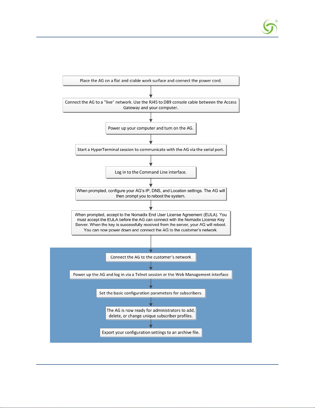
ACCESS GATEWAY
Installation Workflow
The following flowchart illustrates the steps that are required to install and configure your Access Gateway
successfully. Review the installatio n workflow before attempting to install the Access Gateway on the
customer’ s network.
36 Installing the Access Gateway

ACCESS GATEWAY
Powering Up the System
Use this procedure to establish a direct cable connection between the Access Gateway and your laptop
computer, and to power up the system.
1.
Place the Access Gateway on a flat and stable work surface.
2.
Connect the power cord.
3.
Connect the RJ45 console cable between the Access Gateway’s Console port and the female DB9
to the serial port or USB to serial adapter of your computer.
4.
Turn on your computer and allow it to boot up.
5.
Turn on the Ac cess Gateway.
Connect the RJ45 console cable here
Installing the Access Gateway 37

ACCESS GATEWAY
User Manua l and Documentation
The Nomadix product user manuals, product documentation and support files including MIB, XML DTD and
sample dictionary files are located at the following URL:
http://www.nomadix.com/support
If you have any problems, please contact our technical support team at +1.818.575.2590, or email:
support@nomadix.com.
This quick start document provides instructions and reference material for getting star te d with the Nomadix
Access Gateway products, specifically the AG 2400, AG 2500, AG 5800, and AG 5900.
38 Installing the Access Gateway

ACCESS GATEWAY
Start Here
1.
Unpack the Nomadix Access Gateway and place the product on a flat and stable work surface.
2.
Register the gateway for support services by completing and ret urning the Nomadix Gateway
Registration Form; hardcopy enclosed or obtain the form online at
http://www.nomadix.com/registration.
3.
Connect the power cord.
4.
Connect to the Access Gateway (AG). There are two ways to connect to the Access Gateway
(AG):
Connect the RJ45 console cable to the product’s console port and the DB9 female to your computer.
Start a HyperTerminal (or equivalent) session to communicate with the AG via the product’s console
interface. Use the followi ng co nfi g ura ti on settings for your sessio n:
Bits per Second Da t a Bits Parity Stop Bits Flow Control
Serial Connection:
9600
8
None
1
None
Subscriber-side Ethernet Connection:
Connect an Ethernet cable between the product’s Eth1 port and your computer’s Ethernet port.
Setup a SSH client to establish a SSH se ssion to communicate with the NSE gateway via
5.
the
administrative IP address after the Access Gateway finishes powering up. The administrative IP
address is 172.30.30.172.
IP Address 172.30.30.173
Netmask 255.255.0.0
Gateway 172.30.30.172
DNS (If Required) 4.2.2.1
6.
Turn on the product. You can then configure the WAN for a static IP address, DHCP Client or PPPoE client
using appropriate configuration guidelines that follow in order to obtain the license ke y. Onc e the key has
been obtained, the web management interface (WMI) can be used to continue configuration.
LCD Messages
Some Access Gateway hardware models are equipped with an LCD panel, that displays the following system
information:
Platform and Firmware Version Installed
Primary IP Address of the NSE
NSE ID
Active Subscribers.
Installing the Access Gateway 39

ACCESS GATEWAY
Configuring minimal WAN interface connectivity parameters:
Configuration
Note: The WAN port of the AG must be connected to a live network that can access the Internet in order to
retrieve the license key from the license key server.
Log in by typ i ng admin then password: admin. Type (y)es when prompted to configure settings. The initial
minimal WAN port configuration mode will be displayed as shown in Figure 1.
Ready. Press enter to login. NSE
Login: admin <Enter>
Password: ***** <Enter>
NO LICENSE KEY HAS BEEN ENTERED. A LICENSE KEY MUST BE ENTERED IN
ORDER TO PROCEED WITH INSTALLATION.
SEE USER'S GUIDE FOR LICENSE KEY INFORMATION.
INSTALLATION WILL NOW TRY TO
IN ORDER TO PROCEED, THE NSE MUST BE ABLE TO CONNECT TO THE INTERNET.
CONTACT THE NOMADIX LICENSE KEY SERVER.
DO YOU WANT TO CONFIGURE THE
Configuring minimal WAN interface connectivity parameters:
Configuration Mode [static] (static, dhcp, pppoe) :
Figure 1: Initial minimal WAN port configuration.
Select the desired configuration mode and use the following steps to configure the WAN port for either Static
IP, DHCP client or PPPoE.
NSE'S IP AND DNS SETTINGS? [yes/no]: y
Step 1a: Static WAN IP Configuration
Accept static as the default configuration mode and enter the following mandatory settings shown in Figure 2.
Configuration Mode [static ] (static, dhcp, pppoe) :
IP Address [10.0.0.10 ] : Your WAN IP address
Subnet Mask [255.255.255.0 ] : Your subnet mask
Gateway IP [10.0.0.1 ] : Your gateway IP address
WAN 802.1Q tagging [Disabled ] :
VLAN ID [1 ] :
DNS Domain Name [nomadix.com ] :
DNS Server 1 [0.0.0.2 ] : Your primary DNS IP
DNS Server 2 [0.0.0.0 ] :
DNS Server 3 [0.0.0.0 ] :
40 Installing the Access Gateway

ACCESS GATEWAY
Figure 2: Initial WAN port settings
A WAN port summary page will then be displayed as shown in Figure 3.
Port Name : WAN
Port Role : wanIf
Configuration Mode : static
IP Address : Your IP address
Subnet Mask : Your subnet mask
Gateway IP : Your gateway IP address
WAN 802.1Q tagging : Disabled
VLAN ID : 1
DNS Domain Name : nomadix.com
DNS Server 1 : Your primary DNS IP address
DNS Server 2 :
DNS Server 3 : 0.0.0.0
Additional NAT IP addresses : Disabled
show all - Show all WAN Interface configuration
show interface <name> - Show a single WAN Interface configuration
modify interface <name> - Modify a single WAN Interface configuration
Type b to go back, <esc> to abort, ? for help.
Ethernet port/WAN interface configuration>
Figure 3: WAN port static IP configuration summary page.
If everything is correct in the summary, type (b)ack to return to the previous menu, and proceed to Step 2
to enter the location information.
Otherwise, select an option from the Ethernet port configuration menu to display or make changes
to the WAN port settings. When finished with the settings, type b(ack) to return to the previous
menu, and go to Step 2.
Step 1b: DHCP Client Configuration
Type (d) hcp for the configuration mode as shown in Figure 4.
Configuring minimal WAN interface connectivity parameters:
Configuration Mode [static ] (static, dhcp, pppoe) : d
WAN 802.1Q tagging [Disabled ] :
VLAN ID [1 ] :
DNS Server 3 [0.0.0.0 ] :
Figure 4: Selecting DHCP Client for W AN co nfiguration.
Installing the Access Gateway 41

ACCESS GATEWAY
A WAN port summary page will then be displayed as shown in Figure 5.
Port Name : WAN
Port Role : wanIf
Configuration Mode : dhcp
IP Address : Your IP address
Subnet Mask : Your subnet mask
Gateway IP : Your gateway IP addrss
WAN 802.1Q tagging : Disabled
VLAN ID : 1
DNS Domain Name : Your domain name
DNS Server 1 : Your primary DNS IP address
DNS Server 2 :
DNS Server 3 : 0.0.0.0
Additional NAT IP addresses : Disabled
show all - Show all WAN Interface configuration
show interface <name> - Show a single WAN Interface configuration
modify interface <name> - Modify a single WAN Interface configuration
Type b to go back, <esc> to abort, ? for help.
Ethernet port/WAN interface configuration>
Figure 5: WAN port DHCP client configuration summary page.
If everything is correct in the summary, type (b)ack to return to the previous menu, and proceed to step 2 to
enter location information.
Otherwise, select an option from the Ethernet port configuration menu to display or make changes to the
WAN port settings. When finished with settings, type b(ack) to return to the previous menu, and go to step 2.
Step 1c: PPPoE Dynamic IP Client Configuration
Enter (p)ppoe when prompted. Enter the following mandatory settings for a PPPoE c onnection with dynamic
PPP IP configuration shown in Figure 6.
Configuring minimal WAN interface connectivity parameters:
Port Role [wanIf ] : (outOfService, subscriberIf, wanIf)
Configuration Mode [static ] (static, dhcp, pppoe) : p
PPPoE Service Name [ ] : ("none" to clear) : Your Service
LCP Echo-Request Interval [30 ] :
Maximum LCP Non-responses [6 ] :
PPP Authentication User Name [ ] : ("none" to clear) : Your User Name
PPP Authentication Password [ ] : ("none" to clear) : Your Password
42 Installing the Access Gateway

ACCESS GATEWAY
PPP IP Configuration Mode [dynamic ] (dynamic, static) :
Type b to go back, <esc> to abort, ? for help. Ethernet port/WAN
PPP Static IP Address [0.0.0.0 ] :
PPP Maximum TCP MSS [1452 ] :
WAN 802.1Q tagging [Disabled ] :
VLAN ID [1] :
DNS Domain Name [nomadix.com ] :
DNS Server 3 [0.0.0.0 ] :
Figure 6: Selecting PPPoE with dynamic IP configuration.
A WAN port summary page will then be displayed as shown in Figure 7.
Port Name : WAN
Port Role : wanIf
Configuration Mode : pppoe
IP Address : Your IP address
Subnet Mask : Your subnet mask
Gateway IP : Your gateway
PPPoE Service Name : Your Service Name
LCP Echo-Request Interval : 30
Maximum LCP Non-responses : 6
PPP Authentication User Name : Your user name
PPP Authentication Password : Your password
PPP IP Configuration Mode : dynamic
PPP Static IP Address : 0.0.0.0
PPP Maximum TCP MSS : 1452
WAN 802.1Q tagging : Disabled
VLAN ID : 1
DNS Domain Name : Your domain name
DNS Server 1 : Your dns server IP address
DNS Server 2 : 0.0.0.0
DNS Server 3 : 0.0.0.0
Additional NAT IP addresses : Disabled
show all - Show all WAN Interface configuration
show interface <name> - Show a single WAN Interface configuration
modify interface <name>- Modify a single WAN Interface configuration
interface configuration>
Figure 7: WAN port PPPoE client configuration summary page.
Installing the Access Gateway 43

ACCESS GATEWAY
If everything is correct in the summary, type (b)ack to return to the previous menu, and proceed to step 2 to
enter location information.
Otherwise, select an option from the Ethernet port configuration menu to display or make changes to the
WAN port settings. When finished with settings, type b(ack) to return to the previous menu, and go to step 2.
Step 1d: PPPoE Static IP Client Configuration
Use the same steps for configuring dynamic PPPoE shown in Figure 6 above, but select static for PPP IP
Configuration Mode, and enter your IP addr ess for PPP Static IP Address. A summary page similar to
Figure 7 above will be displayed.
If everythi ng is correct in the summary, type (b)ack to return to the previous menu, and proceed to step 2 to
enter location information.
Otherwise, select an option from the Ethernet port configuration menu to display or make changes to the
WAN port settings. When finished with settings, type b(ack) to return to the previous menu, and go to step 2.
Step 2: Entering Your Location Information
You will be required to enter location information in order to obtain the license key. Enter the following
mandatory location information details shown in Figure 8.
Ethernet port/WAN interface configuration>b
Please enter your Company Name [ ]: Your company name
Please enter your Site Name [ ]: Your site name
Please enter your Address (Line 1) [ ]:
(Line 2) [ ]:
(City) [ ]: Your site city
(State) [ ]: Your site state
(ZIP/Postal Code) [ ]:
(Country) [ ]: Your site country
Please enter your E-Mail Address [ ]: email address
Please select the venue type that most reflects your location
1. Apartment
...
25. Other
Please enter a number from the above list: Venue Type
Figure 8: Site location details.
Step 3: Retrieving Your License Key
The system will now prompt you to accept or decline the End User License Agreement (EULA). You must
accept the terms of the EULA before the AG can retrieve its license key. To retrieve the license key, enter
(y)es as shown in Figure 9. The AG retrieves the license key from the Nomadix license key server, then
reboots.
44 Installing the Access Gateway

ACCESS GATEWAY
PLEASE READ THE NOMADIX END USER LICENSE AGREEMENT ('AGREEMENT')
INCLUDED WITH THE NOMADIX PRODUCT.
BY USING THIS SOFTWARE, YOU INDICATE YOUR ACCEPTANCE OF THE
AGREEMENT. I AGREE TO THE TERMS AND CONDITIONS OF THE NOMADIX END
USER LICENSE AGREEMENT.
(Y)ES (N)O
y
The system will now try to contact the Nomadix License Key Server.
Please wait...
Received key from License Key Server.
If the license key is successfully processed the unit will reboot...
Figure 9: License key retrieval
NOTE: The date and time Software License Subscription start date.
Step 4: Configuring the Syste m
You have now established a basic configuration for the AG that enables internet connectivity.
Before you can log into the AG and use the graphical Web Management Interface (WMI), you must disable
subscriber-sid e HTTP:
1.
Log in to the AG
2.
Navigate to Configuration -> Access Control -> Interface
3.
Press Enter until you reach Subscriber-side HTTP
4.
Enter disabled
You can now use the graphical Web Management Interface (WMI) to configure the product’s features.
Step 5: Configuring AG DHCP Server Settings
DHCP Server is enabled by default. T o configure the DHCP Server, go to DHCP under the Configuration
menu. You can either modify the default DHCP pool or delete/add another DHCP pool. The total lease pool
size recommendation is 5 times more than the number of licensed subscribers
DHCP Parameter Your Settings Default Values
DHCP Services (Disable) no
DHCP Relay (Yes / No)
If No, skip to DHCP Server
DHCP Relay Server IP Address blank
DHCP Relay Agent IP Address blank
DHCP Server (Yes / No)
Only if the DHCP Relay is disabled
no
yes
DHCP Server IP Address 10. 0. 0.4
Installing the Access Gateway 45

ACCESS GATEWAY
DHCP Parameter Your Settings Default Values
DHCP Server Subnet Mask 255.255.255.0
DHCP Pool Start IP Address 10.0.0.12
DHCP Pool End IP Address 10.0.0.72
DHCP Lease Minutes 1440
An example of a basic network inc luding an AG is shown below.
46 Installing the Access Gateway

ACCESS GATEWAY
The Management Interfaces (CL I and Web)
The Access Gateway supports various methods for managing the system remotely. These
include, an embedded graphical Web Management Interface (WMI), an SNMP client, or
Telnet. However, until the unit is installed and running, system management is performed
from the Access Gateway’s embedded CLI via a direct serial cable connection. The CLI can
also be accessed remotely.
Until the unit is installed on the customer’s network and a remote connection is established, the CLI is the
administrator’s window to the system. This is where you establish all the Access Gateway start-up
configuration parameters, depending on the customer’s network architecture.
The Access Gateway Menu is your starting point. From here, you access all the system administration items
from the 5 (five) primary menus available:
• Configuration
• Network Info
• Port-location
• Subscribers
• System
Although the basic functional elements are the same, the CLI and the WMI have some
minor content and organizational differences. For example, in the WMI the “subscribers”
menu is divided into “Subscriber Administration” and “Subscriber Interface.” See also
“Menu Organization (Web Management Interface)” on page 57.
Making Menu Selections and Inputting Data with the CLI
The CLI is character-based. It recognizes the fewest unique characters it needs to correctly identify an entry.
For example, in the Access Gateway Menu you need onl y enter
must enter
su to access the Subscribers menu and sy to access the System menu (because t hey both start with
c to access the Configuration menu, but you
the letter “s”).
You may also do any of the following:
Enter b (back) or press Esc (escape) to return to a previous menu.
Press Esc to abort an action at any time.
Press Enter to redispla y the current menu.
Press ? at any time to access the CLI’s Help screen.
When using the CLI, if a procedure asks you to “enter sn,” this means you must type
sn and press the Enter
key. The system does not accep t data or commands until you hit the Enter key.
Menu Organization (Web Management Interface)
When you have successfully installed and configured the Access Gateway from the CLI, you can then access
the Access Gateway from its embedded Web Management Interface (WMI). The WMI is easier to use (point
and click) and includes some i tems not found in the CLI. You can use either interface, depending on your
preference.
For a complete description of all features available in the WMI, see Using the Web Management Interface
(WMI) on page 64.
Installing the Access Gateway 47

ACCESS GATEWAY
Inputting Data – Maximum Character Lengths
The following table details the maximum allowable character lengths when inputting data:
Data Field Max. Characters
All Messages (billing options) 72
All Messages (subscriber error messages) 72
All Messages (subscriber login UI) 72
All Messages (subscriber “other” messages) 72
Description of Service (billing options Plan) 140
Home Page URL 237
Host Name and Domain Name (DNS settings) 64
IP / DNS Name (passthrough addresses) 237
Label (billing options plan) 16
Location settings (all fields) 99
Partner Image File Name 12
Password (adding subscriber profiles) 128
Port Description (finding ports by description) 63
Redirection Frequency (in minutes)
Reservation Number 24
Username (adding subscriber profil es) 96
Valid SSL Certificate DNS Name 64
2,147,483,647
(recommend 3600)
48 Installing the Access Gateway

ACCESS GATEWAY
Online Documentation and Help
The Web Management Interface (WMI) incorporates an online help system that is accessible from the main
window.
Other online documentation resources, available from our corporate Web site (www.nomadix.com/support),
include a full PDF version of this User Guide (viewable with Acrobat™ Reader), How-To Guides, README
files, white papers, technical notes, and business cases.
Installing the Access Gateway 49

ACCESS GATEWAY
Establishing the Start Up Configuration
The CLI allows you to administer the Access Gateway’s start-up configuration settings.
When establishing the start-up configuration for a new installation, you are connected to
the Access Gateway via a direct serial connection (you do not have remote access
capability because the Access Gateway is not yet configured or connected to a network).
Once the installation is complete (see Installation Workflow on page 36) and the
system is successfully configured, you will have the additional options of managing the
Access Gateway remotely from the system’s Web Management Interface, an SNMP client
manager of your choice, or a simple Telnet interface.
The startup configuration must be established before connecting the Access Gateway to a customer’s network.
The “start up” configuration settings include:
Assigning Login User Names and Passwords – You must assign a unique login user name and
password that enables you to administer and manage the Access Gateway securely.
User names and passwords are case-sensitive.
Setting the SNMP Parame te rs (op tional) – The SNMP (Simple Network Management Protocol)
parameters must be established before you can use an SNMP client (for example, HP OpenView) to
manage and monitor the Acces s Gateway remotel y.
Enabling the Logging Options (recommended) – Servers must be assigned and set up if you want to
create system and AAA (billing) log files, and retrieve error messages generated by the Access
Gateway.
Assigning the Location Information and IP Addresses (Connecting the Access Gateway to the
Customer’s N etwork):
Assigning the Network Interface IP Address - This is the public IP address that allows
administrators and subscribers to see the Access Gateway on the network. Use this address
when you need to make a network connection with the Access Gateway.
Assigning the Subnet Mask – The subnet mask d efines the number of IP addresses that are
available on the routed subnet where the Access Gateway is located.
Assigning the Default Gateway IP Address – This is the IP address of the router that the
Access Gateway uses to transmit data to the Internet.
Assigning Login User Names and Passwords
When you initially powered up the Access Gateway and logged in to the Management Inte r face , the default
login user name and password you used was “admin.” The Access Gateway allows you to define 2 concurrent
access levels to differentiate between managers and operators, where managers are permitted read/write access
and operators are restricted to read access only. Once the logins have been assigned, managers have the ability
to perform all write co mmands (Submit, Reset, Reboot, Add, Delete, etc.), but operators cannot change any
system settings. When Administration Concurr ency is enabled, one manager and three operators can access
the Access Gateway at any one time (the default setting for this feature is “disabled”).
1.
Enter sy (system) at the Access Gateway Menu. The System menu appears.
Enter lo (login).
2.
The system prompts you for the current login. If t his is the first time you are changing the login
parameters since initializing the Access Gateway, the default login name and password is “admin.”
50 Installing the Access Gateway

ACCESS GATEWAY
The system accepts up to 11 characters (any character type) for user names and
passwords. All user names and passwords are case-sensitive.
3.
When pro mpt ed, confirm the current login para meters and enter ne w ones.
Sample Screen Response:
System>lo
Enable/Disable Administration Concurrency [disabled]: e
Current login: admin
Current password: *****
Enter new manager login: newmgr
Enter new password: *******
Retype new password: *******
The administrative login and password were changed Enter new
operator login: newop
Enter new operator password: *****
Retype new operator password: *****
The operator login and password were changed
Enter RADIUS remote test login: rad
Enter new RADIUS remote test password: *****
Retype new RADIUS remote test password: *****
The RADIUS remote test login and
password were changed
You must use the new login user na me(s) and password(s) to access the system.
Setting the SNMP Parameters (optional)
You can address the Access Gateway using an SNMP client manager (for example, HP OpenView). SNMP is
the standard protocol that regulates network management over the Internet. To do this, you must set up the
SNMP communities and identifiers. For more information about SNMP, see “Using an SNMP Manager” on
page 65.
If you want to use SNMP, you must manually turn on SNMP.
1.
Enter c (configuration) at the Access Gateway Menu. The Configuration menu appears.
2.
Enter sn (snmp).
3.
Enable the SNMP daemon, as required. The system displays any existing SNMP contact information and
prompts you to enter new information. If this is the first time you have initialized the SNMP command
since removing the Access Ga teway from its box, the system has no information to display (there are no
defaults).
4.
Enter the SNMP parameters (communities and identifiers). The SNMP parameters include your contact
information, the get/set communities, and the IP address of the trap recipient. Your SNMP manager needs
this informati on to enable netwo rk management ove r the Internet.
5.
If you enabled the SNMP daemon, you must reboo t the system for your changes to take effect. In this
case, enter y (yes) to reboot your Access Gateway.
Sample Screen Response:
Configuration>sn
Enable the SNMP Daemon? [Yes]:
Enter new system contact: newname@domainname.com
[Nomadix, N ewbury Park, CA ]
Enter new system location: Office, Newbury Park, CA Enter read/get community [public] :
Installing the Access Gateway 51

ACCESS GATEWAY
Enter write/set community [private]:
Enter IP of trap recipient [0.0.0.0]: 10.11.12.13
SNMP Daemon: Enabled
System contact: newname@domainname.com
System location: Office, Newbury Park, CA
Get (read) community: public
Set (write) community: private T rap recipient: 10.11.12.13
Reboot to enable new changes? [yes/no] y
Rebooting...
You can now address the Access Gateway using an SNMP client manager.
Configuring the WAN interface
If a license key is not present, you will still be directed to set up the WAN configuration as soo n as you log
into the CLI . However, the subsequent steps are new and network settings are no longer configured unde r
Location.
The following are the steps needed to configure the main WAN interface:
1.
Enter c (configuration) at the Access Gateway Menu. The Configuration menu appears.
2.
Enter eth (ethernet).
3.
After you have entered “yes” to the initial prompt, enter “mod int WAN” or “m i WAN” (“modify
interface WAN”). Note that modes and interface names are case sensitive. The configuration then steps
through the s ettings one by one.
4.
Port role for the WAN port should be already set to WAN, just hit <enter>
5.
Set the configuration mode to match your network settings.
6.
Set the remaining network settings .
7.
Default uplink and download speed is 15 Mbps. Enter different values if desired.
8.
Bandwidth and DNS settings are configured separately for each WAN interface. You can configure them
later in the WAN configuration dialog in the Web Management Interface.
9.
If you do not wish to configure additional NAT IP addresses at this time, type “b”.
10.
A summary of the WAN port settings is now displayed; if they are correct, type “b” again.
You will now see the Nomadix loca tion configuration page. Enter contact data and agree to the Nomadix End
User License Agreement. Your license will be retrieved when you enter “y”. The NSE will then reboot to
activate your license settings.
52 Installing the Access Gateway

ACCESS GATEWAY
Enabling the Logging Options (recommended)
System logging creates log files and error messages generated at the system level. AAA logging creates
activity log file s for the A AA ( Authentication, Author i za tion, and Accounting) fu nct io ns . Y o u can ena b le
either of these options.
Although the AAA and billing logs can go to the same server, we recommend that they
have their own unique server ID number assigned (between 0 and 7). When managing
multiple properties, the properties are identified in the log files by their IP addresses.
When system logging is enabled, the standard SYSLOG protocol (UDP) is used to send all message logs
generated by the Access Gateway to the specified server.
1.
Enter log (logging) at the Configuration menu. The sys tem displays the current logging status (enabled or
disabled).
2.
Enable or disable the system and/or AAA logging options, as required. If you enable either option, go to
Step 3, otherwise logging is disabled and you can terminate this procedure.
3.
Assign a valid ID number (0-7) to each server.
4.
Enter the IP addresses to identify the location of the system and AAA SYSLOG servers on the network
(the default for both is 0.0.0.0).
When logging is enabled, log files and error messages are sent to these servers for future retrieval. To see
sample reports, go to Sample SYSLOG Report on page 241 and Sample AAA Log on page 240.
Sample Screen Response:
Configuration>log
Enable/disable System Log [disabled ]: enable
Enter System Log Number (0-7) [0 ]: 2
Enter System Log Filter
0: Emergency
1: Alert
2: Critical
3: Error
4: Warning
5: Notice
Installing the Access Gateway 53

ACCESS GATEWAY
6: Info
7: Debug
Select an option from above [7]: 7
Enter System Log Server IP [255.255.255.255]: 10.10.10.1 0
Enable/disable System Log Save to file [disabled ]: enable
Enable/disable AAALog [disabled ]: enable
Enter AAA Log Number (0-7) [0 ]: 2
Enter AAA Log Filter
0: Emergency
1: Alert
2: Critical
3: Error
4: Warning
5: Notice
6: Info
7: Debug
Select an option from above [7]: 7
Enter AAA Log Server IP [255.255.255.255]: 10.10.10.1 0
Enable/disable AAA Log Save to file [disabled ]: enable
Enable/disable RADIUS Hist ory Log [disabled ] : enable
Enter RADIUS History Log Number (0-7) [0 ]:2
Enter RADIUS History Log Filter
0: Emergency
1: Alert
2: Critical
3: Error
4: Warning
5: Notice
6: Info
7: Debug
Select an option from above [6]: 7
Enter RADIUS History Log Server IP [255.255.255.255]: 10.10.10.10
Enable/disable RADIUS History Log Save to file [disabled ]: enable
Enable/disable System Report Log [disabled ]: enable
Enter System Report Log Number (0-7) [0 ]: 2
Enter System Report Log Server IP [255.255.255.255]: 10.10.10.1 0
Enter System Report Log interval (minutes) [0]: 5
Enable/disable Tracking Log [disabled ]: enable
Enter Tra c king Log Number (0-7) [0 ]: 2
Enter Tracking Log Server IP [255.255.255.255]: 10.10.10.1 0
Enable/disable Tracking Log Save to file [disabled ]:
Enable/Disable Name Reporting [disabled ]: enable
Enable/Disable Port Reporting [disabled ]: enable
Enable/Disable Location Reporting [disabled ]: enab le
Enable/Disable 500th Packet Count Reporting [disabled ]: enable
Syst em Log Enabled
System Log Number 2
System Log Filter 7
System Log Ser ve r IP 10.10.10.10
System Log Save to file Enabled
AAA Log Enabled
AAA Log Number 2
AAA Log Filter 7
54 Installing the Access Gateway

ACCESS GATEWAY
AAA Log Server IP 10.10.10.10
AAA Log Save to file Enabled
RADIUS History Log Enabled
RADIUS History Log Number 2
RADIUS History Log Filter 7
RADIUS History Log Server IP 10.10.10.10
RADIUS History Log Save to file Enabled
System Report Log Enabled
System Report Log Number 2
System Report Log Server IP 10.10.10.10
System Report Log Interval (in minutes) 5
Tracking Log Enabled
Tracking Log Number 2
Tracking Log Server IP 10.10.10.10
Tracking Log Save to file Disabled
Tracking Name Reporting Enabled
Tracking Port Reporting Enabled
Tracking Location Reporting Enabled
Tracking Report every 500th packet Enabled
WARNING: Communication between the gateway and the syslog server may need to be secured to comply with local
laws. Consider routing communication through an IPSec tunnel.
Configuration>
Logging Out and Powering Down the System
Use this procedure to log out and power down the Access Gateway.
1.
Enter l (logout) at the Access Gateway Menu. Your serial session closes automatically.
2.
Turn off the Access Gateway and disconnect the power cord.
3.
Disconnect the cable between the Access Gateway and your computer.
Connecting the Access Gateway to the Customer’s Network
Use this procedure to connect the Access Gateway to the customer’s network (after the startup configuration
parameters have been established).
1.
Choose an appropriate physical location that allows a minimum clearance of 4cm either side of the unit
(for adequate airflow).
2.
Connect the Access Gateway to the router, then connect the Access Gateway to the customer’s subscriber
port.
3.
Connect the power cord and turn on the Access Gateway.
4.
Go to Establishing the Basic Configuration for Subscribers on page 56.
Installing the Access Gateway 55

ACCESS GATEWAY
Establishing the Basic Configuration for Subscribers
When you have successfully e s tablished the startup configurati on and installed the unit onto the customer’s
network, connect to the Access Gateway via Telnet. You must now set up the basic configuration parameters
for subscribers, including:
Setting the DHCP Options – DHCP (Dynamic Host Configuration Protocol) allows you to assign IP
addresses automatically (to subscribers who are DHCP enabled). The Access Gateway can “relay”
the service through an external DHCP server or it can be configured to act as its own DHCP server.
Setting the DNS Options – DNS (Domain Name System) allows subscribers to enter meaningful
URLs into their browsers (instead of complicated numeric IP addresses). DNS converts the URLs
into the correct IP addresses automatically.
Setting the DHCP Options
When a device connects to the network, the DHCP server assigns it a “dynamic” IP address for the duration of
the session. Most users have DHCP capability on their computer. To enable this service on the Access
Gateway, you can either enable the DHCP relay (routed to an external DHCP server IP address), or you can
enable the Access Gateway to act as its own DHCP server. In both cases, DHCP functionality is necessary if
you want to automatically assign IP addresses to subscribers.
The Access Gateway’s adaptive configuration technology provides Dynamic Address
Translation (DAT) functionality. DAT is automatically configured to facilitate “plug-andplay” access to subscribers who are misconfigured with static (permanent) IP addresses, or
subscribers that do not have DHCP capability on their computers. DAT allows all users to
obtain network access, regardless of their computer’s network settings.
1.
Enter c (configuration) at the Access Gateway Menu. The Configuration menu appears.
2.
Enter dh (dhcp).
By default, the Access Gateway is configured to act as its own DHCP server and the relay
feature is disabled. Please verify that your DHCP Server supports DHCP packets before
enabling the relay. Not all devices containing DHCP servers (for example, routers) support
DHCP Relay functionality.
When assigning a DHCP Relay Agent IP address for the DHCP Relay, ensure that
the IP address you use does not conflict with devices on the network side of the
Access Gateway.
Although you cannot enable the DHCP relay and the DHCP service at the same
time, it is possible to “disable” both functions from the Command Line Interface.
In this case, a warning message informs you that no DHCP services are available
to subscribers.
3.
Follow the on-screen instructions to set up your DHCP options. For example:
Sample Screen Response:
Configuration>dh
Enable/Disable IP Upsell [disabled ]:
Enable/Disable DHCP Relay [disabled ]:
Enable/Disable DHCP Server [enabled ]:
Enable/Disable Subnet-based DHCP Service [disabled ]:
Enable/Disable For ward ed DHCP Clients [disabled ]:
IP Upsell Disabled
DHCP Relay Disabled
56 Installing the Access Gateway

ACCESS GATEWAY
External DHCP Server IP 0.0.0.0
DHCP Relay Agent IP 0.0.0.0
DHCP Server Enabled
DHCP Server Subnet -based Disabled
Forwarded DHCP Clients Disabled
Server-IP Server-Netmask Start-IP End-IP Lease Type IPUp
208.11.0.4 255.255.0.0 208.11.0.5 208.11.0.7 20 PRIV NO
10.0.0.4 255.255.255.0 10.0.0.5 10.0.0.250 30 PRIV NO *
* Default IP Pool
DHCP IP Pools Configuration:
0 - Show IP Pools
1 - Add a new IP Pool
2 - Modify an IP Pool
3 - Remove an IP Pool
4 - Exit this menu
Select the DHCP Pool configuration mode [0]:
DHCP Options from RFC 2132
You can configure DHCP options as defined in RFC 2132. The configured options are sent to subscribers who
obtain their network configuration from the NS E via DHCP.
This capability only applies to the NSE’s DHCP Server function. There is no change to the NSE’s operation
as a DHCP client.
The options are configurable on a per-pool basis. Different sets of options can be configured for different
pools.
A given DHCP option consists of an option code and a value. RFC 2132 details the various available options,
and the data type for each. The NSE will validate the data entered to ensure that it is type-correct for the
option code in question. If it is incor rect, the option is not accepted.
Numerical integer values can be entered in decimal format, or hex format using a “0x” prefix.
The following DHCP option codes are supported:
Option Description Option Code
Single IP address 16, 28, 32
List of one or more IP addresses 3-5, 7-11, 41-42, 44-45, 48-49, 65, 69-76
List of zero or more IP addresses 68
List of one or more pairs of IP addresses (or address/mask pairs) 21, 33
32-bit unsigned integer value 2, 24, 35, 38
16-bit unsigned integer value 13, 22, 26
8-bit unsigned integer value 23, 37, 46
List of 1 or more 16-bit unsigned integer values 25
Single octet Boolean (value may be 1 or 0) 19-20, 27, 29-31, 34, 36, 39
Installing the Access Gateway 57
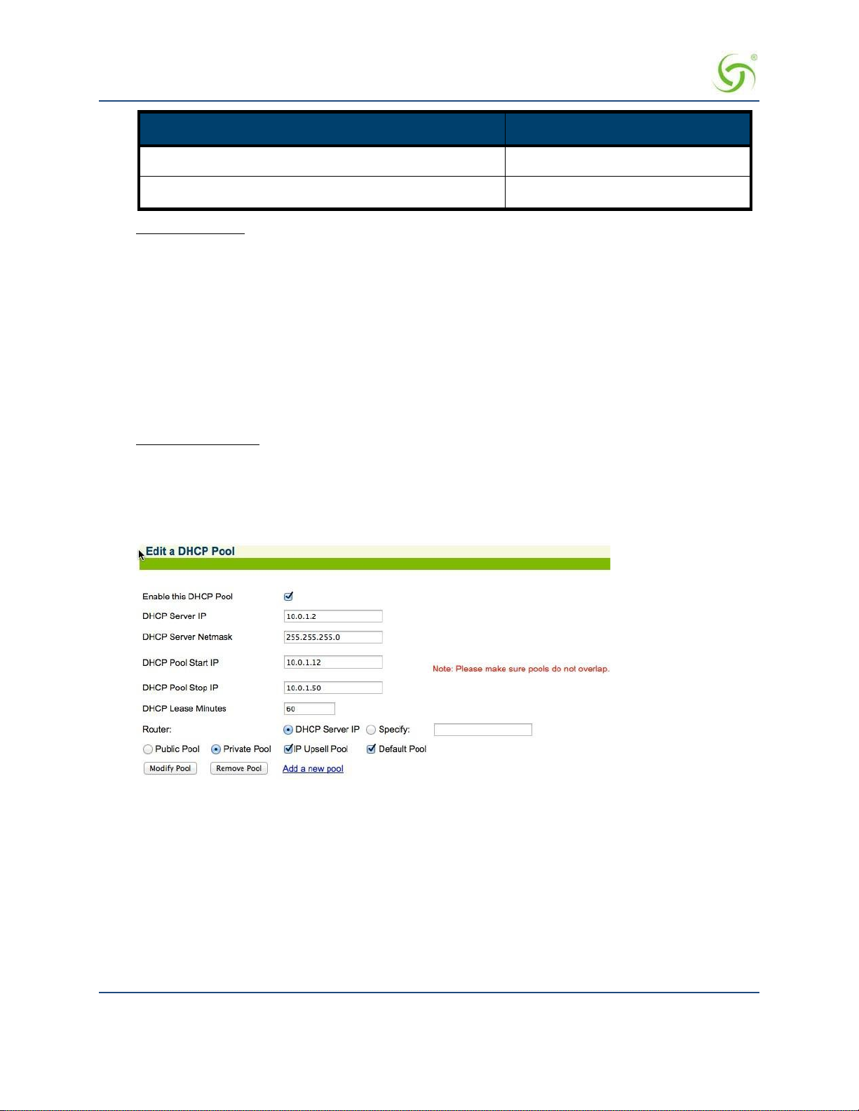
ACCESS GATEWAY
Option Description Option Code
Sequence of 1 or more octets 43
Ascii string of 1 or more printable characters 12, 14, 17-18, 40, 47, 64, 66-67
Disallowed options: Some option codes are not allowed, for one of the following reasons:
Items that are already configured elsewhere as a separate DHCP pool or NSE configuration
parameter, and/or are derived from one that is. Includes options 1 (subnet mask), 3 (router), 6
(domain name server), 15 (domain name), 51 (lease time), 54 (server identifier), 58 (renewal time),
59 (rebinding time).
Items not valid in a DHCP offer or ACK message. Includes options 50 (requested IP address), 55
(parameter request list), 56 (error message), 57 (maximum message size), 60 (vendor class
identifier), 61 (client identifier).
Items generated automatically by the mechanism of DHCP message construction, which carry no
application information. Includes options 0 (pad), 52 (option overload), 53 (DHCP message type),
255 (end).
Unrecognized options: Options 62-63, 77-254 are unrecognized. Some of these codes are legitimate and are
defined in other RFCs, while others are not defined. These option codes are not explicitly disallowed on the
NSE, but the NSE is “unaware” of them – that is, it will make no attempt to validate either the code or the
data. It is the administrator’s respo nsibility to ensure that the option codes and data entered are legitimate.
The following screens illustrate a dding additional DHCP options to a DHCP Pool.
58 Installing the Access Gateway
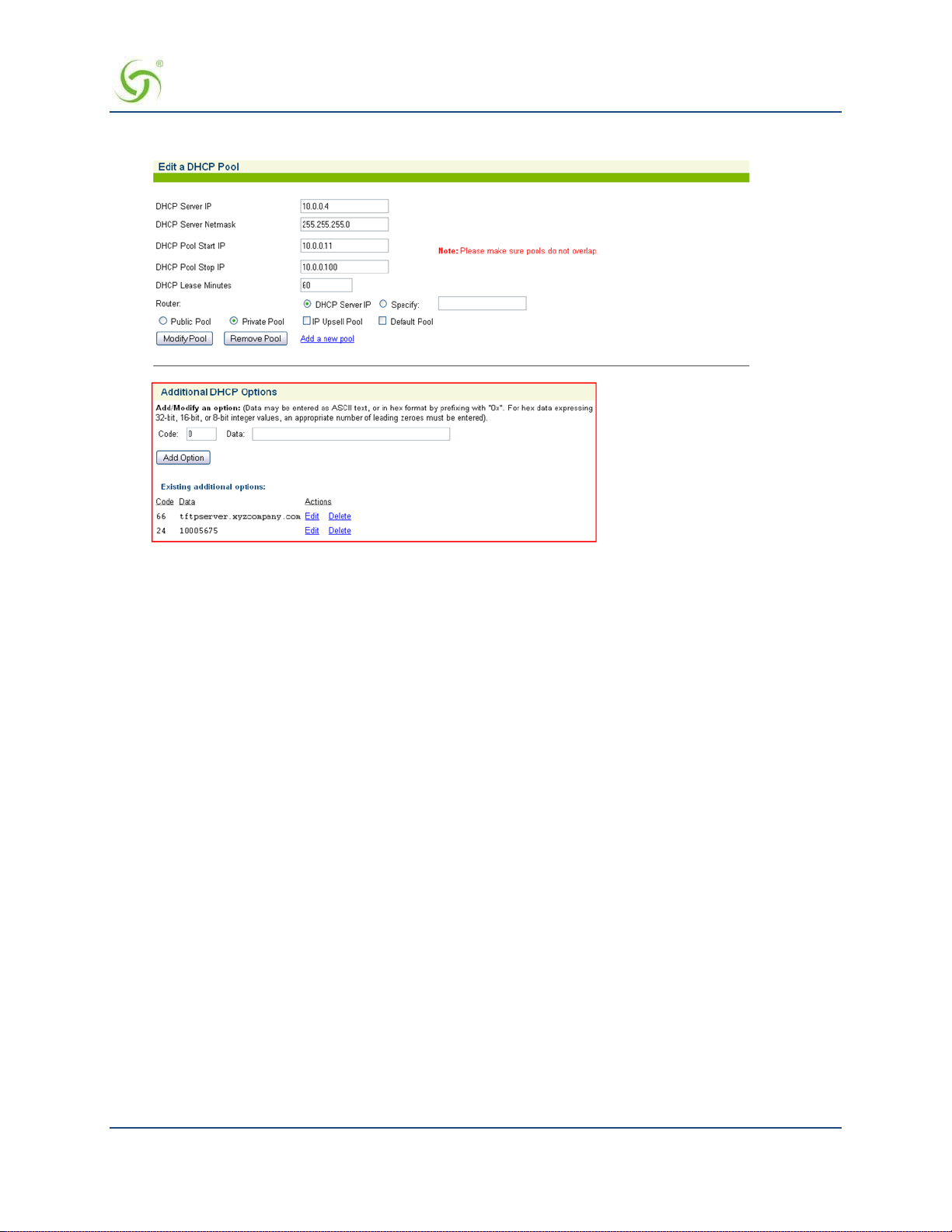
ACCESS GATEWAY
DHCP Dynamic Enable and Disable
Click Configuration->DHCP. Click the Server-IP and Enable this DHCP Pool. Note that DHCP
enable/disable is dynamic, no reboot required.
Setting the DNS Options
DNS allows subscribers to enter meaningful URLs into their browsers (instead of numeric IP addresses) by
automatically converting the URLs into the correct IP addresses.
After you have configured DNS global options in the command-line interface, you can assign a primary,
secondary, or tertiary (third) DNS server for each WAN in the Web Management Interface (WMI). See
Ethernet Ports / WAN on page 93 for WAN-specific DNS configuration.
To set the DNS global configuration options:
1.
Enter c (configuration) at the Access Gateway Menu. The Configuration menu appears.
2.
Enter dn (dnsglobal) at the Configuration menu.
3.
Enter the ho s t name (the DNS name of the Access Gateway). The host name must not conta i n any
spaces.
4.
Specify the Redirection Port Mode. If floating, the DNS will use ephemeral ports for the source port of
DNS requests. If
5.
Specify the UDP DNS Redirection Port.
6.
Enable (default) or disable DNSSEC (Domain Namer System Securit y Extensions).
Sample Screen Response:
fixed (default), the manually configured ports are used.
Configuration>dn
Enter host name (no spaces) [AG5x00 ]:usg
Redirection Port Mode (Fixed/Flo ating) [fixed ]:
Installing the Access Gateway 59

ACCESS GATEWAY
Enter UDP DNS Redirection Port [1029 ]:
Enter Proxy UDP DNS Port [1028 ]:
Enable/Disable DNSSEC [enabled ]:
Host Name usg
DNS Redirection Port Mode fixed
UDP DNS Redirection Port 1029
Proxy UDP DNS Port 1028
DNSSEC Support enabled
60 Installing the Access Gateway

ACCESS GATEWAY
Archiving Your Configuration Settings
Once you have installed your Access Gateway and established the configuration set tings, you should write the
settings to an archive file. If you ever experience problems with the system, your archived settings can be
restored at any time.
Refer to the following procedures:
Exporting Configuration Settings to the Archive File {Export}” on page 194.
Importing Configuration Settings from the Archive File {Import}” on page 197.
Installing the Access Gateway 61

ACCESS GATEWAY
Installing the Nomadix Private MIB
The Nomadix Private Management Information Base (MIB) allows you to view and manage SNMP objects
on your Access Gateway. To use the MIB, you must obtain the appropriate nomadix.mib file for your Access
Gateway. This file is available in the S upport area of the Nomadix web site.
Obtaining the Management Information Base (MIB) file
1.
Visit www.nomadix.com/support.
2.
Scroll to “Gateway Documenta tion”.
3.
Click “Latest Documentation”
4.
Scroll to the group for your Access Gateway model.
5.
Click the link to download the MIB file for your Access Gateway.
Click to download the
MIB file.
Configuring the Management Information Base
1.
Import the nomadix.mib file into your SNMP client manager.
Connect to the Access Gateway from a node on the network that is accessible via the
2.
Gateway’s network port (Internet, LAN, etc.). Be sure to enable the SNMP daemon on the Access
Gateway (available on the Access Gateway’s CLI or Web Management Interface, under the
Configuration menu –
All variables defined by Noma dix start with the following prefix:
3.
snmp).
iso.org.dod.internet.private.enterprises.nomadix
You should now be able to define queries and set the SNMP values on your
4.
Access
Gateway. If necessary, consult this User Guide or your SNMP client
manager’s documentation for further details.
We recommend that you change the predefined community strings in order to maintain a
secure environment for your Access Gateway.
Access
62 Installing the Access Gateway

ACCESS GATEWAY 3
System Administration
This section provides all the instructions and procedures necessary for system administrators to manage the
Access Gateway on the customer’s network (after a successful installation).
The system administration procedures in this section are organized as they are listed under their respective Web
Management Interface (WMI) menus:
Configuration Menu on page 68
Network Info Me n u on page 144
Port-Location Menu on page 151
Subscriber Administration Menu on page 160
Subscriber Interface Menu on page 170
System Menu on page 192
Now that the Access Gateway has been installed and configured successfully, this User
Guide moves away from the Command Line Interface (CLI) and documents the Access
Gateway from the Web Management Interface (WMI) viewpoint.
System Administration 63

ACCESS GATEWAY
Choosing a Remote Connection
Once installed and configured for the customer’s network, the Access Gateway can be managed and
administered remotely with any of the following interface options:
Using the Web Management Interface (WMI)―Provides a powerful and flexible Web interface for
network administrators.
Using an SNMP Manager ― Allows remote “Windows” management using an SNMP client
manager (for example, HP OpenView). However, before you can use SNMP to access the Access
Gateway, you must set up the appropriate SNMP communities. For more information, refer to
Managing the SNMP Com munities {SNMP} on page 136.
Using a Telnet Client
To use any of the remote connections (Web, SNMP, or Telnet), the network interface IP
address for the Access Gateway must be established (you did this during the installation
process).
Choose an interface connection, based on your preference.
Using the Web Management Interface (WMI)
The Web Management Interface (WMI) is a “graphical” version of the Command Line Interface, comprised
of HTML files. The HTML files are embedded in the Access Gateway and are dynamically linked to the
system’s functional command sets. You can access the WMI from any Web browser.
Your browser preferences or Internet options should be set to compare loaded pages with
cached pages.
To connect to the Web Management Interface, do the following:
1.
Establish a connection to the Internet.
2.
Open your Web browser.
3.
Enter the network interface IP address of the Access Gateway (set up during the installation process).
4.
Log in as usual (supplying your user name and password).
To access any menu item from the WMI, click on the item you want. The corresponding work screen then
appears in the right side frame. From here you can control the features and settings related to your selection.
Although the appearance is very different from the Command Line Interface, the information displayed to you
is basically the same. The only difference between the two interfaces is in the method used for making
selections and applying your changes (selections are checkable boxes, and applying your changes is achieved
by pressing the Save button). Pressing the Restore button resets the screen to its previous state (clearing all
your change s without applyin g t hem).
Selecting the language of the Web Management Interface
You can click on Language Selection to change t he language of the Web Management Int erface text.
Currently English (U.S.) and Chinese (simplified) are provided.
64 System Administration

ACCESS GATEWAY
Using an SNMP Manager
Once the SNMP communities are established, you can connect to the Access Gateway via the Internet using
an SNMP client manager (for example, HP OpenView). SNMP is the standard protocol used in the Network
Management (NM) system. Thi s system contains two primary elements:
Manager – The console (clien t) through which s ys tem administrators perform networ k
management functions.
Agent – An SNMP-compliant device which stores data about itself in a Management Information
Base (MIB). The Access Gateway is an example of such a device.
The Access Gateway contains managed objects that directly relate to its current operational state. These
objects include hardware configuration parameters and performance statistics.
Managed objects are arranged into a virtual information database, called a Management Information Base
(MIB). SNMP enables managers and agents to communicate with each other for the purpose of accessing these
MIBs and retrieving data. See also Installing the Nomadix Private MIB on page 62.
The following example shows a (partial) SNMP screen response.
Using a Telnet Client
There are many Telnet clients that you can use to connect with the Access Gateway. Using Telnet provides a
simple terminal emulation that allows you to see and interact with the Access Gateway’s Command Line
Interface (as if you were connected via the serial interface). As with any remote connection, the network
interface IP address for the Access Gateway must be established (you did this during the installation process).
System Administration 65

ACCESS GATEWAY
Logging In
To access the Access Gateway’s Web Management Interface, use the Manager or Operator login user name
and password you defined during the installation process (refer to Assigning Login User Names and
Passwords).
User names and passwords are case-sensitive.
66 System Administration

ACCESS GATEWAY
About Your Product License
Some features included in this section will not be available to you unless you have purchased the appropriate
product license from Nomadix . In this case, the following statement will appear either immediately below the
section heading or when the feature is mentioned in the body text:
Your product license may not support this feature. You can upgrade your product license
at any time.
System Administration 67

ACCESS GATEWAY
Configuration Menu
Defining the AAA Services {AAA}
This procedure shows you how to set up the AAA (Authentication, Authorization, and Accounting) service
options. AAA Services are used by the Access Gateway to authenticate, authorize, and subsequently bill
subscribers for their use of the customer’s network. The Access Gateway currently supports several AAA
models that are discussed in Subscriber Managem ent on page 213.
1.
From the Web Management Interface, click on Configuration, then AAA. The Authentication
Authorization and Accounting Settings screen appears:
2.
Enable or disable AAA Services. If you enable AAA Services, go to Step 3; otherwise this feature is
disabled and you can exit the procedure.
3.
Select a Logout IP address from the drop-down list. The list contains IP address that can be used as the
logout IP address. The default IP address is 1.1.1.1.
4.
Click Configure to configure t he XML Interface, as required.
68 System Administration
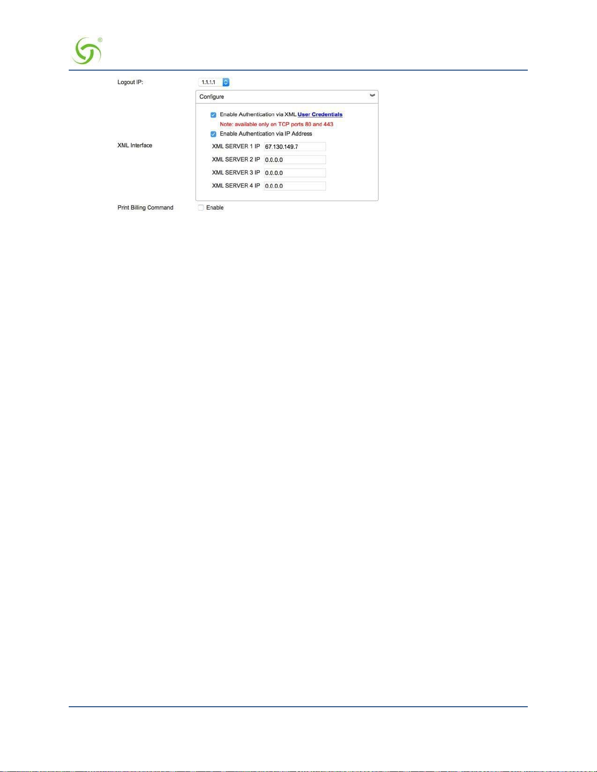
ACCESS GATEWAY
XML is used by the Access Gateway’s subscriber management module for port location and user
administration. Enabling the XML interface allows the Access Gateway to accept and process XML
commands from an external source. XML commands are sent over the network to the Access Gateway.
The Access Gateway parses the query string, executes the commands specified by the string, and returns
data to the system that initiated the command request.
You can authenticate XML commands via user credentials, as well as via IP addresses. You can choose
either or both authenticatio n mechanisms.
• If you select Enable Authentication via XML User Credentials, confirm that an XML user has
been set up. Either click on the User Credentials link, or select System > Login to set or confirm
the XML Login ID and password.
Below is an example XML command i nitiation that relies on XML User authentication:
wget http://NSE_IP/usg/command. xml -O out.tx t
--auth-no-challenge --user=xmlcommand
--password=xmlcommand --post-file="addUser.xml"
--header="Content-Type:text/xml"
• If you select Enable Authentication via IP Address, enter the valid XML server address(es). Up
to four addresses are supported.
5.
Enable or disable Print Billing Command, as required. This feature enables NSE to support Driverless
Print servers. If this feature is enabled, you must enable the XML interface and enter the IP address for the
XML interface (Step 3 and Step 4). With Print Billing enabled, print servers can b ill subscribers’ rooms
for printing their documents without them having to install printers.
The DNS name print.server.com will internally resolve to the Configured Print Server UR L that is
entered in the configuration. When subscribers are redirected to the Print Server the NSE adds
Parameters to that request, so that the Server is able to charge the proper subscriber.
With these variables sent to the server it can now send the XML command to bill the users properly.
Print Server IP needs to be entered as one of the XML server IP for the command to successfully
complete.
The XML command is:
<USG COMMAND="BILL_PRINT" IP_ADDR="">
<ROOM_NUM></ROOM_NUM>
<DOC_NAME></DOC_NAME>
<NUM_COPIES></NUM_COPIES>
System Administration 69

ACCESS GATEWAY
<NUM_PAGES></NUM_PAGES>
<COST></COST>
<TIME_SUBMITTED></TIME_SUBMITTED>
</USG>
Subscribers could get to print.server . c om by:
ICC button link
Printout in the hotel room
Link from the hotel’s HPR Page
Your product license may not support this feature.
6.
Enable or disable the AAA Passthrough Port feature, as required. System administrators can set the
Access Gateway to pass-through HTTPS traffic, in addition to standard port 80 traffic, without be ing
redirected. When access to a non-HTTPS address (for example, a Search Engine or News site) has been
requested, the subscriber is then redirected as usual.
7.
If AAA passthrough is enabled, enter the corresponding port number.
The port number must be different than 80, 2111, 1111, or 1112.
8.
Enable or disable the 802.1x Authentication Support feature, as required.
Both AAA and RADIUS Authentication must be enabled for 802.1x Authentication
support.
9.
Enable or disable the Origin Server (OS) parameter encoding for Portal Page and EWS feature, as
required.
10.
You can choose to Enable failover to Internal Web Server Authentication if Portal Page/External
Web Server is not reachable by placing a check in that box.
11.
Enable or disable Port Based Billing Policies.
With Port Based Billing Po licies enabled, you can individually configure the billing methods (RADIUS,
PayPal, PMS) and the billing plans available on each port.
This ability allows for having d ifferent billing methods and billing plans on different por ts identified by
VLANs or SNMP Port Query of the concentrator. A practical application of this feature is to have a
normal hotel room with a plan A that is $9.99 for a day with PMS billing and have a meeting room with a
plan of $14.99 an hour with PayPal billing.
In order for the port-based policies to work, you must enable Port Based Billing Policies. See also Adding
and Updating Port-Loc ati on A s si gn ments {A dd} on page 151.
12.
Enable or disable HTTPS Redirection.
The NSE re s ponds to regular HTTP requests from pe nding subscriber s with a redirection to the login
screen. The NSE does not respond to HTTPS requests from pending sub s cribers (HTTP requests with a
destination port = 443) with a redirect; this will result in a timeout or invalid certificate warning.
Enabling HTTPS Redirection adds a security exception to the user’s browser to allow the certificate
received from the NSE to be always “valid.”
70 System Administration

ACCESS GATEWAY
13.
Enable or disable Facebook Login. If you enable Facebook login, you must provide a Facebook App ID
and Facebook App secret code. Instructions for creating these are available from Facebook.
14.
Depending on which authoriz ation mode you choose, go to the following sub-sections in this procedure:
Enabling AAA Services with the Internal Web Server – The IWS is “flashed” into the system’s
memory and the subscriber’s login page is served directly from the Access Gateway.
Enabling AAA Services with an External Web Server – In the EWS mode, the Access Gateway
redirects the subscriber’s login request to an external server (transparent to the subscriber). The login
page served by the EWS reflects the “look and feel” of the solution provider’s network and presents
more login options.
Enabling AAA Services with the Internal Web Server
You are here because you want to enable the AAA Services with the Access Gateway’s Internal Web Server. The
Access Gateway maintains an internal database of authorized subscribers, based on their MAC (hardware
address) and user name (if enabled). By referring to its database record, also known as an authorization table,
the Access Gateway instantly recognizes new subscribers on the network.
You can configure the Access Gateway to handle new subscribers in various ways (see the table on this page).
With the IWS, you also have the option of enabling SSL support.
After selecting the Internal Web Server authorization mode, you have the option of enabling or disabling the
Usernames and New Subscribers fea tures. These features work in conjunction with each other to determine
how new subscribers are handled. Refer to the following table:
Usernames New Subscribers System Response
Disabled Enabled Allows new subscribers to enter the system without giving a user name and
password.
Enabled
(optional)
Enabled Disabled New subscribers are not allowed. Only existing subscribers are allowed after
Disabled Disabled You will not use this combination unless you want to lock out all
Enabled Allows new subscribers or authentication by their user name and password.
authenticating their user name and password.
subscribers.
System Administration 71

ACCESS GATEWAY
1.
Select the Internal Web Server tab.
2.
Enable or disable the SSL Support feature, as required. If you enable SSL Support, you must provide
Certificate DNS Name.
a valid
For more information about setting up SSL, go to Setting Up the SSL Feature on page 251.
SSL support allows for the creation of an end-to-end encrypted link between the Access Gateway and
its clients by enabling the Internal W e b Server (IWS) to display pages under a secure link—important
when transmi tting AAA information in a network.
Adding SSL support to the Acce ss Gateway requires service providers to obtain digital c e r tificates
from VeriSign™ to create HTTPS pages. Instructions for obtaining certificates are provided by
Nomadix.
To enable SSL Support, your Access Gateway’s flash must include the server.pem,
cakey.pem, and cacert.pem certificate files (the “cacert.pem” file is provided with your
Access Gateway). For assistance, contact Technical Support.
3.
If you want to designate a portal page, you must enable the Portal Page feature; otherwise leave this
feature disabled.
The Portal Page IP or DNS address are added to the IP passthrough list automatically.
4.
If you enabled the Portal Page feature, provide the following supporting information:
Portal Page URL
Parameter Passing (enabled or disabled)
Parameter Signing (includi ng Method, Parameters, and Shared Secret)
See Redirection Parameter Signing on page 74 for more information about parameter
signing.
Portal XML POST URL, target for the NSE’s USER_STATUS XML commands
72 System Administration

ACCESS GATEWAY
Portal XML Post Port
Support GIS Clients (enabled or disabled)
GIS stands for Generic Interface Specification, a document written by iPass.
Enabling the Smart Client option in the Access Gateway automatically supports all GIS
compliant clients using the Internal Web Server. Enabling “Support for GIS Clients” under
the Portal Page feature means that the Access Gateway will defer the management of the
GIS clients to the Portal Page server.
Block IWS Login Page (enabled or disabled)
5.
Enable or disable the Usernames feature, as required (refer to the table in Enabling AAA Services wit h
the Internal Web Server on page 71).
Some subscribers may want additional account flexibility and security for their services (for example, if
they use mor e than one comput er and their MAC add ress changes, or if they move betwee n portlocations). In this case, a subscriber can define a unique user name and password which they can use from
any machine or location (witho ut b e ing re- charged). Subscribers who choose this option are prompted for
their user name and password whenever they try to access the Internet. Solution providers can charge a
fee for this service.
6.
Enable or disable the New Subscribers feature (refer to the table in Enabling AAA Services with the
Internal Web Server on page 71).
New Subscribers must be enabled before enabling the PayPal and PMS options.
7.
If you enabled New Subscribers, enable or disable the Relogin After Timeout option.
8.
You can now enable or disable the PayPal feature. When this feature is enabled, subscribers are
prompted to enter either their PayPal account information or their credit card information (for billing
purposes). The Access Gateway is configured to use PayPal. You will need to open a business account
with PayPal before this feature can be used.
Please contact Nomadix Technical Support for assistance. Refer to Contact Information on page 268.
All data communications between the Access Gateway and PayPal are encrypted by the
SSL (Secure Sockets Layer) protocol. The Access Gateway never “sees” subscriber credit
card numbers.
9.
If the PayPal Service is enabled, enter the in fo rmation for the following fields:
PayPal App Name
Check whethe r this is a live en vi ronment. Leave unchecked if it is a sandbox /testing environment
Client ID
Set the Secret Code
WebHook ID
All the above settings will be obtained when creating the PayPal Business account. Please
contact Support for documentation explaining the setup of the PayPal account.
10.
Enable or disable Smart Client Support, as required.
11.
Click on the Save b utton to save your changes, click on Save then Reboot to reboot the Access Gateway
and make the changes take effect immediately, or click on the Restore button if you want to reset all the
values to their previous state.
System Administration 73
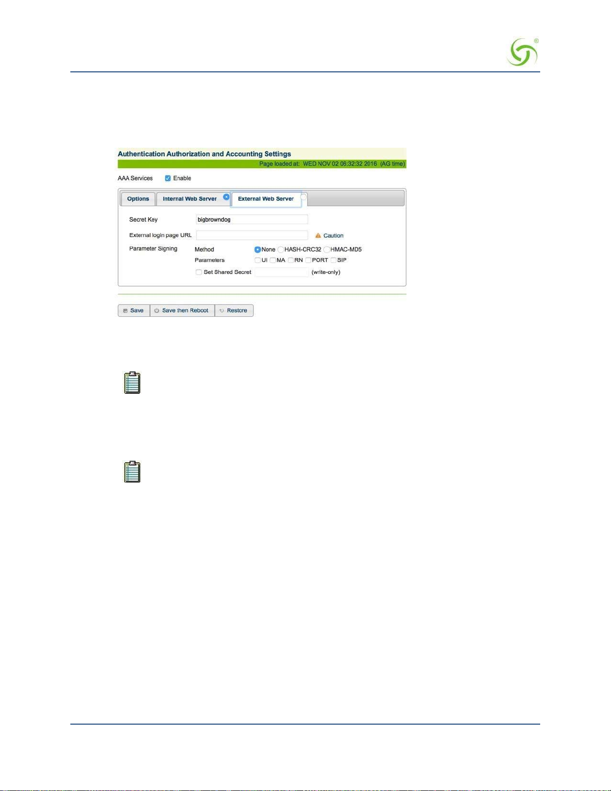
ACCESS GATEWAY
Enabling AAA Services with an External Web Server
You are here because you want to enable the AAA Services with an External Web Server (EWS). In the EWS
mode, the Access Gateway redirects the subscriber’s login request to an external server.
1.
Select the External Web Server tab.
Enter the Secret Key (The Access Gateway and the external authorization server must use
2.
secret key). The Secret Key ensures that the response the Access Gateway gets from the External Web
Server is valid.
DNS must be configured if you want to enter meaningful URLs instead of numeric IP
addresses into any of the Access Gateway’s configuration screens (for example, the
External login page URL in the following step).
the same
3.
Enter a valid External login page URL.
4.
Configure the Parameter Signing options.
See Redirection Parameter Signing for more information about parameter signing.
Click on the Save button to save your changes, cl i ck on Save then Reboot to reboot the
5.
and make the changes take effect immediately, or click on the
Restore button if you want to reset all the
Access Gateway
values to their previous state (makin g changes to the EWS settings does not require a system reboot).
Redirection Pa rameter Signing
External Web Server (EWS) and Internal Web Server (IWS) Portal Page Parameters can be digitally signed,
preventing malicious subscribers from intercepting, forging and replaying URL redirection strings used by the
NSE and EWS or IWS Portal Page to validate subscriber access. This capability eliminates a vulnerability that
was previously exploited to gain unauthorized Internet access at charge-for-use sites.
The signing feature can create a cryptographically strong signature that protects the sensitive portions of a
URL redirection string (i.e., NSE I D, MAC address of the subscriber, etc), while letting the EWS/Portal Page
verify that t he URL string has not been tampered or forged by the subscriber.
74 System Administration

ACCESS GATEWAY
The feature is configured by selecting a signing method, the parameters to be signed, and assigning a secret
key.
Two signature methods are supported:
HASH-CRC32
HMAC-MD5
Not all parameters that are part of the URL redirection string need to be included in the signature calculation.
The following parameters are considered sensitive and can be selected:
UI (the ID of the NSE)
MA (the subscriber’s MAC address)
RN (the Room Number)
PORT (the port number the subscriber is connected to)
The desired secret key simply needs to be entered in the field. Once entered, it is not visible to the user.
Information that indicates which parameters were signed, along with the resultant hash value, are then
included in s ome additional parameters that are appended to the redirection string.
In order to utilize the parameter signing feature, the EWS or Portal Page Server used must be configured to
correctly parse and verify the signing information. Documentation that includes guidelines for configuring a
server to support signing can be obtained by contacting Nomadix Technical Support.
Establishing Secure Administration {Access Control}
The Access Gateway allows you to block administrator access to interfaces (Telnet, WMI and FTP, SSH and
SFTP) and incorporates a master access control list that checks the source (IP address) of administrator logins.
A login is permitted only to the interfaces that have not been blocked, and only if a match is made wit h the
master “Source IP” list contained on the Access Gateway. If a match is not made with the “Source IP list,” the
login is denied, even if a correct login name and password are supplied. The access control list for source IPs
supports up to 50 (fifty) entries in the form of a specific IP address or range of IP addresses.
This procedure allows you to enable the “Access Control” feature and block administrator access to specific
interfaces, and add or remove administrator “Source IP” addresses.
System Administration 75

ACCESS GATEWAY
The NSE supports secure https connections to the Web Management Interface (WMI). Correct certificates
must be installed on the NSE flash memory for these connections to function properly. The same certificate
set that is used to support SSL connections for subscribers is used for this purpose. For documentation about
configuring the system to support secure connections, contact technical support. See Appendix A: Technical
Support.
In addition, corresponding options to block https connections (independent of http) are included in the NSE's
Access Control functionality, for both the network and subscriber sides.
If the required certificates are not resident on the flash, an attempted https connection will generate an error
syslog.
1.
From the Web Management Interface, click on Configuration, then Access Control. The Access Control
screen appears.
2.
For Configurable Ports, enter a Telnet Port and an HTTP or HTTPS Port.
3.
Enable or disable administrator access to any of the following interfaces:
Telnet Access
Web Management Access (HTTP)
Web Management Access (HTTPS)
FTP Access
SFTP Access
76 System Administration

ACCESS GATEWAY
SSH Shell Access
Blocking or unblocking interface access will terminate the current session.
Do not enable the blocking of all interfaces without setting up and enabling
SNMP. Enabling the blocking of all interfaces and disabling SNMP will completely
block access to the Access Gateway administration interface. For assistance,
contact Nomadix Technical Support.
4.
Enable or disable subscriber-side interface blocking for any of the following interfaces
Telnet Access: enables/disables blocking of Telnet access from the subscriber-side to the NSE
Telnet interface. Default setting is enabled.
Web Management Access (HTTP): enables/disables blocking of Web Management access from
the subscriber-side to the NSE WMI. Default setting is enabled.
Web Management Access (HTTPS): enables/disables blocking of secure Web Management
access from the subscriber-side to the NSE WMI. Default setting is enabled.
FTP Access: enables/disables blocking of FTP access from the subscriber-side to the NSE. Default
setting is enabled.
SFTP Access: enables/disables blocking of SFTP access from the subscriber-side to the NSE.
Default setting is enabled.
SSH Shell Access: enables/disables blocking of SSH shell access from the subscriber-
side to the NSE CLI. Default settin g is disabled.
5.
Click the check box for Access Control if you want to enable this feature, then click on the Save
button to save your changes.
If you enabled Access Control, administrator access is restricted only to the IP addresses shown under
the “Currently Access is Permitted for IPs” listing. If you want to add to or remove IP addresses from
the list, go to Step 7.
The Access Control list can contain up to 50 (fifty) valid administrator IP addresses or
ranges of IP addresses.
6.
Click the check box for IPv6 subscriber-side devices if you want to enable this feature.
7.
To add an IP address (or range of IP addresses) to the list, enter the “starting” IP address in the Access
Control Start IP field.
If you are adding a range of IP addresses to the access control list, you must now enter the
8.
address in the
Access Control End IP field. If you are adding a single IP address, enter None in the
Access Control End IP field.
9.
Click on the Add button to add the IP address (or range of IP addresses) to the list.
10.
To remove an IP address (or range of IP addresses) from the list, enter the “starting” IP address in the
Access Control Start IP field.
“ending” IP
If you are removing a range of IP addresses from the access control list, you must now enter the
“ending” IP address in the
Access Control End IP field. If you are removing a single IP address,
enter None in the Access Control End IP field.
11.
Click on the Remove button to remove the IP address (or range of IP addresses) from the list.
If you enabled Access Control and have “locked yourself out,” of the system (for
example, because you’ve forgotten your password), you must establish a local
System Administration 77

ACCESS GATEWAY
serial connection with the CLI to disable the Access Control feature, or change the
range of allowed IP addresses to access the management interfaces.
Defining Automatic Configuration Settings {Auto Configuration}
The Access Gateway allows you to define parameters to enable the automatic configuration of the system.
See also RADIUS-driven Auto Configuration on page 18.
1.
From the Web Management Interface, click on Configuration, then Auto Configuration.
The Autoconfiguration Settings screen appears:
2.
Enable or disable Autoconfiguration, as required.
3.
If you enabled Autoconfiguration, you must enter the following information into the corresponding
fields:
RADIUS Authentication Name
RADIUS Password
Confirm Password
4.
Click on the Save button to save your changes, cl i ck on Save then Reboot to reboot the Access
Gateway and make the changes take effect immediately, or click or the
Restore button to reset all data
to its previous state.
Enabling Auto Configuration
As shown in the diagra m below, two subsequent events drive the automatic configuration of Nomadix
devices:
1.
A flow of RADIUS Authentication Request and Reply messages between the Nomadix gateway and
the centralized RADIUS server that specifies the location of the meta configuration file (containing a
listing of the individual configuration files and their download frequency status) are downloaded
from an FTP server into the fla s h of the Nomadix device.
2.
Defines the automated login into the centralized FTP server and the actual download process into the
flash.
Step 1: RADIUS Authen Req/Response message to determine location of meta configuration file.
Step 2: FTP download of configuration files (secure)
78 System Administration
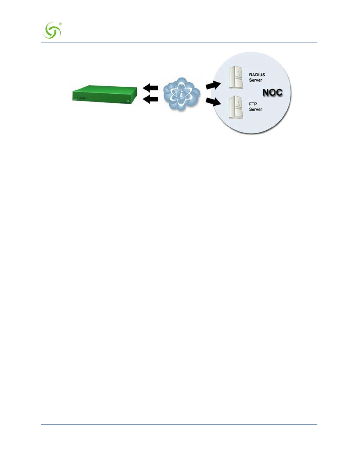
ACCESS GATEWAY
The Auto-Configuration setup requires a few basic steps to be completed by both the field engineer
and the NOC administrator.
Administrative Steps to Enable Auto -Config
Typically, these tasks are performed either at a device pre-staging center or by the field engineer.
1.
Establish a WAN connection and electronically accept the EULA.
2.
Setup RADIUS Server parameters (go to Defining the Realm-Based Routing Settings {RealmBased Routing} on page 130).
3.
Set up Username and Password for RADIUS Authentication.
Administrative Steps to Enable Auto -Config for the NOC Administrator:
1.
Add NAS IP address.
2.
Add Nomadix Auto-Config VSA to the Nomadix dictionary file on the RADIUS server.
3.
Create a RADIUS profile with the configuration VSA.
4.
Create an FTP server with the configuration files.
5.
The following diagram shows a sample RADIUS configuration file, meta file and illustrati on of the
FTP server setup.
System Administration 79

ACCESS GATEWAY
The Nomadix device will automatically initiate one reboot to enable the new settings. Co nfiguration updates
for network maintenance can be accomplished by simpl y enabling the Auto-Configuration option and
rebooting the device (for example, using SNMP). See also Defining Automatic Configuration Settings {Auto
Configuration}.
Setting Up Bandwidth Management {Bandwidth Management}
The Access Gateway allows system administrators to manage the bandwidth for subscribers, defined in Kbps
(Kilobits per seconds) for both upstream and downstream data transmissions. With the ICC feature enabled,
subscribers can increase or decrease their own bandwidth dynamically, and also adjust the pricing plan for
their service.
You can enable or disable bandwidth policies for bandwidth management and group bandwidth management
policies. You can specify settings for each individual WAN. The NSE supports setting default maximum up
and downstream bandwidths for subscribers who do not have a specified bandwidth.
1.
From the Web Management Interface, click on Configuration, then Bandwidth Management. The
Bandwidth Management screen appears:
2.
If required, click the check box for Bandwidth Managemen t Enabled.
80 System Administration

ACCESS GATEWAY
3.
If required, select Group Bandwidth Policies. Bandwidth Management must be enabled before you
can enable and specify Group Bandwidth Policies.
Note: The Bandwidth Management page only globally Enables and Disables Bandwidth Management and
Group Bandwidth Policies. Bandwidth settings themselves are set for each WAN interface in Ethernet
Ports/WAN.
4.
If desired, click the check box to enable Weighted Fair Queuing. See Weighted Fair Queueing on
page 22.
5.
With Weighted Fair Queuing enabled, you have the option to Share Unused Bandwidth. If checked,
unused bandwidth, if available, is distributed among users in proportion to the users’ bandwidth caps. If
unchecked, users are held to their bandwidth cap limits.
6.
If required, specify Default Valid Subscriber Bandwidth; Up and/or Down. These options specify the
default maximum up and down bandwidths for any subscribers that do not have a specified bandwidth
setting. A value of ‘0’ means that no limit will be applied.
7.
Click on the Save button to save your changes, or click the Restore button to reset all the values to their
previous state.
Group Bandwidth Limit Policy
The Group Bandwidth Limit Policy allows the you to assign a common bandwidth rate limiting policy to a
group of subscriber devices. A ll devices within the group share the total bandwidth allocated to the policy.
The Group Bandwidth Limit Policy feature defines the following vendor-specific attributes (VSAs):
Nomadix
VSA #
19 GROUP_BW_POLICY_ID Defines the ID the for the group policy. Integer between 1 and
20 GROUP_BW_MAX_UP Defines the total upstream bandwidth allowed for the group in
21 GROUP_BW_MAX_DOWN Defines the total downstream bandwidth allowed for the group in
Name Role/Value
16777215, inclusive.
Kilobits per second. Integer value. 0 is interpreted as unlimited.
Kilobits per second. Integer value. 0 is interpreted as unlimited.
Group Bandwidth Limit Policy – Operation
The NSE maintains a collection of all installed group bandwidth policies. The collectio n is indexed by the
bandwidth policy ID provided by the RADIUS server. The collection can store as many policy records as the
number of licensed subscriber devices. All subscriber devices sharing the same group bandwidth policy ID
belong to the same group. A subscriber device can participate in only one bandwidth-limiting group at a time.
When a login is performed to an account that returns a bandwidth policy ID that does not yet exist in the NSE,
a new policy record is created and inserted into the aforementioned collection. The subscriber authorized by
the Access-Accept is associated with the newly installed ba ndwidth policy ID, and the bandwidth limits
returned are invoked.
When the Access-Accept for a subscriber contains a bandwidth policy ID already present on NSE, the
subscriber is associated with the existing group policy. All subscribers that are now members of the group
share the total bandwidth allocate d to the policy.
If at some point a login is performed to a n acc ount that returns the policy ID for an existing polic y, but also
returns bandwidth values different than those currently allocated for that policy, the policy will be updated
with the new values found in the Access-Accept. Thus, the latest Access-Accept determines the current rates
for the entire group.
System Administration 81

ACCESS GATEWAY
The lifetime of a group policy record in the collection is determined by the session time of the authorized (i.e.
VALID) subscribers participating in the group. Group policy records are removed from the collection when
the last subscriber device belonging to the group is logged out of the NSE regardless of the reason (e.g.
session timeout, idle timeout, d e le tion of the subscriber by an administrator, etc).
The NSE does not support the ability to enforce both per-subscriber and gr oup bandwidth rate s
simultaneously for the same subscribers. The RADIUS server must specify either per- subscriber or group
bandwidth attributes. However, in case a RADIUS Access-Accept contains both individual and group
bandwidth attributes, the NSE will use the group attributes and ignore the per-subscriber attributes.
The NSE can concurrently support some subscribers as part of a group and some others
with limits set on a per-subscriber basis. However, a single subscriber cannot be assigned
group membership and individual limits at the same time.
Group Bandwidth Limit Policy – Current Table
When the feature is enabled, a group bandwidth policy ID column is displayed in the Current Subscribers
table (Subscriber Administ ration > Current). Once policies are instantiated, policy information can also be
viewed via XML.
Establishing Billing Records “Mirroring” {Bill Record Mirroring}
The Access Gateway can send copies of PayPal transactions and PMS billing records to external servers that
have been previously defined by system administrators. The Access Gateway assumes control of billing
transmissions and saving billing records. By “mirroring” the billing data, theAccess Gateway can also send
copies of billing records to predefined “carbon copy” servers. Additionally, if the primary and secondary
servers are down, the Access Gateway can store up to 2,000 credit card transaction records. When a
connectio n is re- established (with either server), the Access Gateway sends the stored information to the
server—no records are lost!
For more information about the bill record mirroring feature, go to Mirroring Billing Records o n page 260.
1.
From the Web Management Interface, click on Configuration, then Bill Record Mirroring. The Credit
Card Mirroring Settings screen appears:
82 System Administration
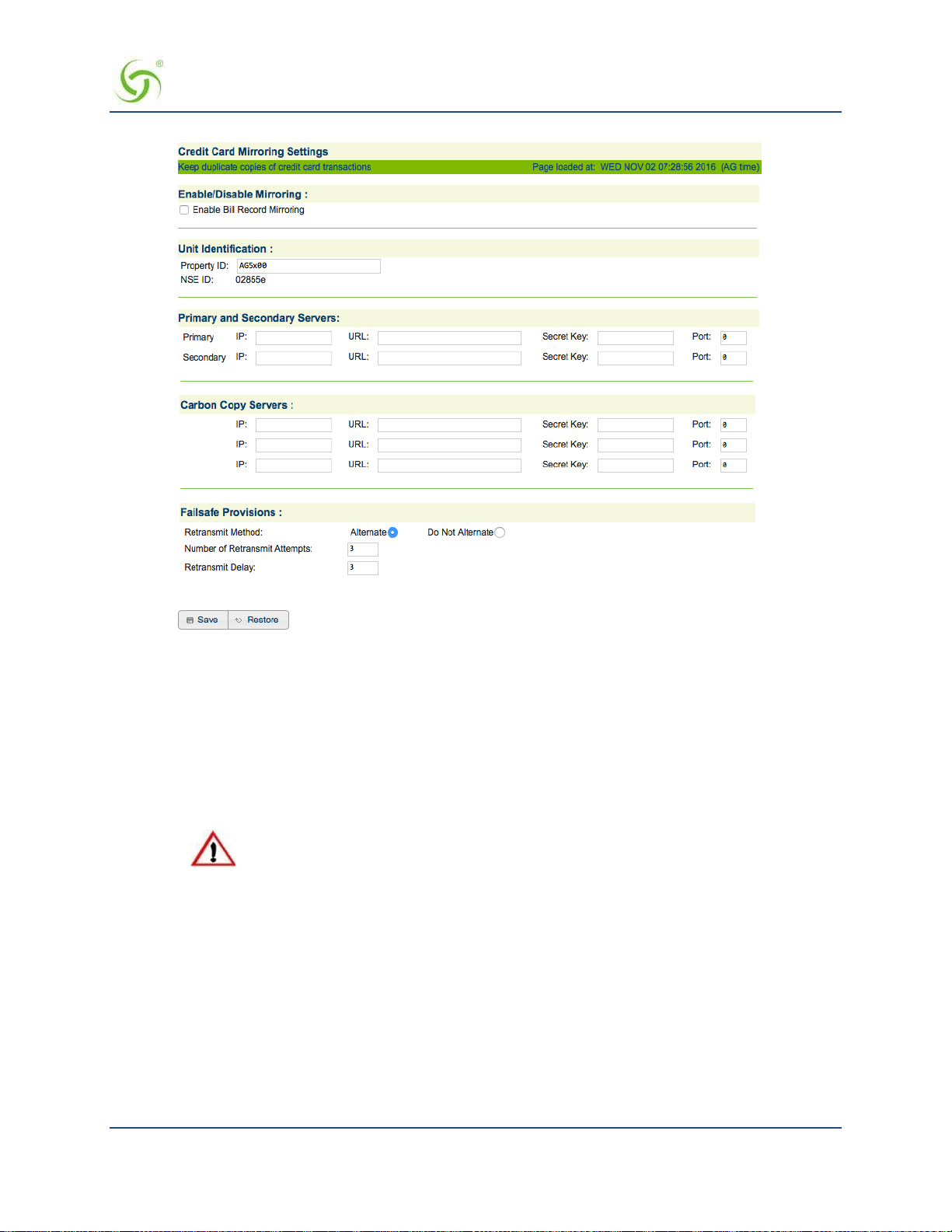
ACCESS GATEWAY
2.
If you want to enable the billing recor ds “mirroring” functionality for credit card transactions,
click on the check box for
3.
Enter the property identification code in the Property ID field.
4.
Enter the communication parameters for the primary server that is to be used for mirroring,
Enable Bill Record Mirroring.
including:
• Primary IP
• URL
• Secret Key
The Access Gateway and the “mirror” servers must use the same secret key.
5.
Repeat Step 4 for the secondary server (if any) and all carbon copy servers.
6.
Define the “fail-safe” provisions, including:
Retransmit Method – Alte rnate, or do not alternate.
Number of Retransmit Attempts – This tells the syste m how many times it should attempt to
retransmit billing records before suspending the task.
Retransmit Delay – This specifies the time delay between each retransmission.
7.
Click on the Save button to save your changes, or click on the Restore button if you want to reset all
the values to their previous state.
System Administration 83

ACCESS GATEWAY
Class-Based Queueing
Nomadix Class-Based Queueing provides a flexible way to control the bandwidth provided to individual
groups of use rs (classes). Classes have both maximum and minimu m bandwidth specifications.
You can add users to classes and apply attributes across entire classes. Each class has 3 configurable
attributes:
Priority
Minimum Bandwidth
Maximum Bandwidth
For additional details, see Class-Based Queueing on page 9.
To Enable and Configure Class-Based Queueing
1.
Click Configuration > Class Based Queueing. The Class Based Queueing screen appears.
2.
Click Enable and then Save to enable Class-Based Queueing.
3.
Click Add Class to add a class. Class names are case-sensitive. “Dot” notation (e.g.,
<top-level class>.<subclass>) is used to associate top-level classes and subclasses.
• Subscribers can only be assigned to sub-classes.
• Sub-classes cannot access bandwidth greater than their assigned WANlink.
• Top-level classes can be assigned a priority of 1 through 8. Sub-classes can be assigned a priority of 1,
2, or 3. One is the highe st priority.
• Minimum bandwidths are respected regardless of priority. Minimums/maximum bandwidth is applied
across all users i n a class.
84 System Administration

ACCESS GATEWAY
4.
Click on a class name to change the class name or modify the attributes of a class.
5.
Click Throughput Estimator to evaluate traffic scenarios. Given different loads per class, the interface
provides the estimated effective throughput. You can use this tool to preview how bandwidth will be
assigned ba sed on Class-Based Q ueueing structure a nd priority settings.
Assigning User s t o a Class
There are four ways to assign users to a particular class:
Radius
XML
Subscriber Administration menu
Subscriber Interface menu
Assigning a User t o Class-Based Queueing Using Radius
Subscribers can be assigned to a specific class/sub-class using Radius VSA. Subscribers with no class
membership are assigned a priority of 8.
ATTRIBUTE Nomadix-Bw-Class-Name 27 string
For example, when a subscriber logs in and this attribute is defined as follows, the subscriber gets assigned to
the class priority1.Subclass.
System Administration 85
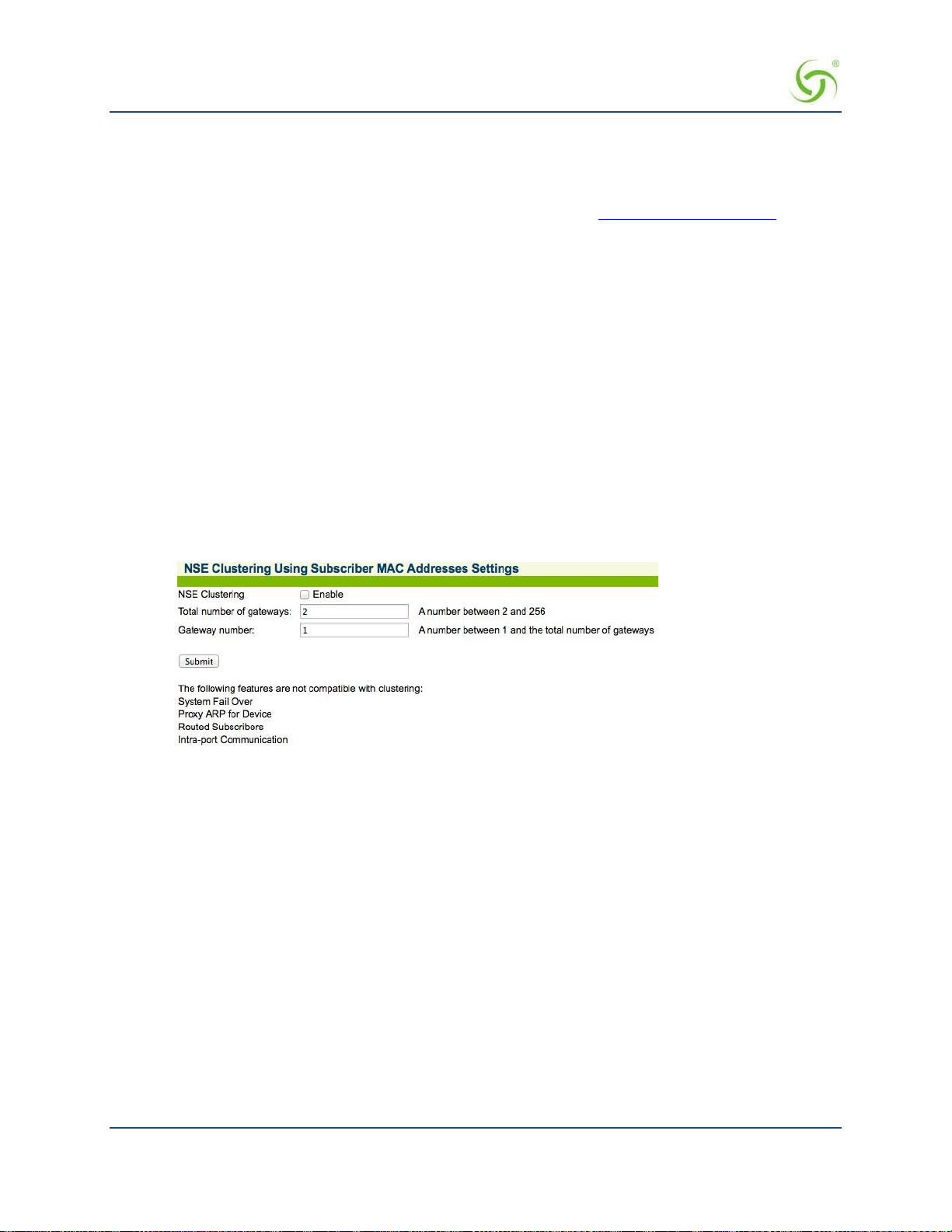
ACCESS GATEWAY
Nomadix-Bw-Class-Name = "priority1.Sub-class"
Assigning a user to a class using XML
The CLASS_NAME element has been added to the USER_ADD and USER_PAYMENT XML command s .
These are covered in the 8.4 XML DTD documentation, available from www.nomadix.com/support.
Assigning a User t o a Class using the Subscriber Administration menu
The procedures for Adding Subscriber Profiles (Subscriber Administration > Add) support adding a
subscriber, device, or group account profile to a class. See Adding Subscriber Profiles {Add} on page 160.
Assigning a User t o a Class Using Bill Plans (Subscriber Interface menu)
You can add a user to a class while setting up a billing plan. See Setting Up a “Normal” Billing Plan on page
173.
Clustering {Clustering}
NSE Clustering provides the ability to cluster multiple gateways on one network segment. For more
information about this feature, including description, limitations, and troubleshoo ting information, see
Multiple Unit Clustering on page 25.
To enable N SE Clustering:
1.
Click Configuration > Clustering and click Enable.
2.
Enter integers for the Total number of gateways and the Gateway number (must be from 2 to 256 with no
gaps). For example, if clustering is being configured on three gateways, one gateway must be 1, one
gateway must be 2 and one gateway must be 3.
Be aware of the following:
All gateways in a cluster must have the same configuration
WAN and INAT IP addresses must not clash among clustered gateways
All gateways must have the same number of licensed subscribers
No restrictions are placed on shared secrets, administrator credentials, RADIUS NAS identifier and
NAS port.
Configuring Destination HTTP Redirection {Destination HTTP Redirection}
Destination HTTP Redirect provides DNS-triggered redirection of HTTP requests to one or more portal page
URLs configured on the NSE. Portal pages could include account status, maps, local information, etc.
The NSE will intercept and respond to DNS queries containing configurable strings. Subscribers requesting a
website at that DNS will obtain a DNS respo n se that contains a “magic” IP address (which is the same value
obtained when the subscriber queries the DNS string “logout.nomadix.com”).
86 System Administration

ACCESS GATEWAY
The NSE will process HTTP requests for that “magic” IP address (configurable on the AAA page), and will
reply with an HTTP redirection (which may include a number of signed redirection parameters) to a
configured URL. By following the HTTP redirection, the subscriber will reach the target URL, and he/she
will then be served a page containing whatever information is relevant (account and/or other specific
information).
The figure above illustrates de stination HTTP redirection, assuming a DNS query string for
www.example.com,
configuration, the following would apply:
• A DNS query for www.example.com is intercepted by the NSE, which responds with the magic IP
address. Then, the subscriber’s browser sends an HTTP request to the magic IP and sets the Host
header to
• The NSE will process the HTTP request and will analyze the Host header to find the redirection URL
that corresponds to www.example.com,
then craft an HTTP redirection response that contains the portal page URL, followed by a query
string. The string will include vario us redirection parameters, time-stamped and signed, if signing is
enabled for that entry (which it is not i n this example).
• The subscriber will follow the redirection string and will land on the portal page URL. The portal
will verif y and analyze the query string and the n will return the relevant information (likely about the
subscriber’s account status, depending on what the portal is configured to handle).
• After successful redirection occurs the list of signed parameters and signature methods are passed to
the portal page.
HTTP/1.0 302 RD
http://portal1.myhotel.com/details?OS=<Original Server>&UI=<NSE’s
ID>&MA=<subscriber’s MAC>&RN=<Room
name>&PORT=<VLAN>&SIP=<subscriber’s IP>&TS=<timestamp>&NONCE=<16
chars>&SIGN=<signature>& SIGNED=<list of signed parameters>&
METHOD=<signature method>
a magic IP address of 1.1.1.1, and a portal page URL of po rtal1.myhotel.com. Given this
www.example.com.
which is portal1.myhotel.com in this example. The NSE will
System Administration 87
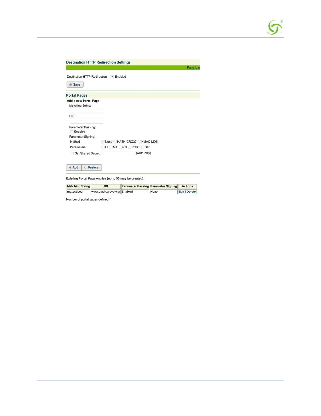
ACCESS GATEWAY
1.
From the Web Management Interface, click on Configuration, then Destina tion HTTP Redirection.
The Destination HTTP R e direction Settings screen appears:
2.
To enable Destination HTTP Redirection, click on the Enabled check box. The default setting is
disabled.
You may create up to 20 portal pages.
3.
In the Portal Pages section, enter the matching string that will be directed to the portal page in the
Matching String field.
4.
Enter the portal page’s URL in the URL field.
5.
To enable parameter passing, click on the Parameter Passing Enable check box.
6.
Select the Parameter Signing:
•
Method: None, HASH-CRC32, or HMAC-MD5 (select one method).
Parameters: UI, MA, RN, and PORT (select all applicable parameters).
•
7.
To enable Set Shared Secret, click on the Set Shared Secret check box. If you enable this feature, enter
the shared secret text string in the
8.
Click on the Save button to save the redirection settings, or click on the Restore button if you want to
Set Shared Secret field.
reset all the values to their previous state.
9.
Portal page setting are saved to the tab le in Existing Portal Page entries section of the screen.
From that table, you can edit or delete existing portal pages.
Managing the DHCP service options {DHCP}
When a device connects to the network, the DHCP server assigns it a “dynamic” IP address for the duration of
the session. Most users have DHCP capability on their computer. To enable this service on the Access Gateway,
you can either enable the DHCP relay (routed to an external DHCP server IP address), or you can enable the
Access Gateway to act as its own DHCP server. In both cases, DHCP functionality is necessary if you want to
automatically assign IP addresses to subscribers.
88 System Administration
 Loading...