

Page 1

Page 2

ACCESS GATEWAY
Access Gateway
Copyright © 2012 Nomadix, Inc. All Rights Reserved.
This product also includes software developed by: The University of California,
Berkeley and its contributors; Carnegie Mellon University, Copyright © 1998 by
Carnegie Mellon University All Rights Reserved; Go Ahead Software, Inc., Copyright
© 1999 Go Ahead Software, Inc. All Rights Reserved; Livingston Enterprises, Inc.,
Copyright © 1992 Livingston Enterprises, Inc. All Rights Reserved; The Regents of the
University of Michigan and Merit Network, Inc., Copyright 1992 – 1995 All Rights
Reserved; and includes source code covered by the Mozilla Public License, Version 1.0
and OpenSSL.
This User Guide is protected by U.S. copyright laws. You may not transmit, copy,
modify, or translate this manual, or reduce it or any part of it to any machine readable
form, without the express permission of the copyright holder.
Page 3

ACCESS GATEWAY
Trademarks
The symbol, and Nomadix Service Engine™ are trademarks
of Nomadix, Inc. All other trademarks and brand names are marks of their respective holders.
Product Information
Telephone: +1.818.597.1500
Fax: +1.818.597.1502
For technical support information, see the Appendix in this User Guide.
Patent Information
Covered by one or more of the following U.S. and foreign patents: US6,130,892; AU740012,
中国发明专利 98805023.4, Israel 131831, Korea 528156, Mexico 222100, New Zealand
337772; US6,868,399; US7,117,526, EU1226687 (validated in: BE1226687, FI1226687,
FR1226687, DE60028229.5, GB1226687, IE1226687, NL122668 7, ES1226687, SE1226687,
CH1226687); US7,197,556, EU1224788 (validated in: BE1224788, CH1224788,
DE60011799.5-08, ES1224788, FI1224788, FR1224788, GB1224788, NL1224788,
SE1224788); US6,636,894, EU1222791 (validated in: BE1222791, FI122279 1, FR1222791,
DE60020588.6, GB1222791, NL1222791, ES1222791, SE1222791, CH 1222 791); SG88575,
中国发明专利 00815828.2, AU2006207853; US6,789,110, Japan 3880856, Korea 559357,
SG88483, 中国发明专利 00815982.3, EU1234425 (validated in: BE1234425, FI12 34425,
FR1234425, DE60029819.1, GB1234425, IE1234425, NL123442 5, ES1234425, SE1234425,
CH1234425); US7,088,727; US6,857,009; US7,194,554, AU779137, Korea 0687837,
SG88465, 中国发明专利 00815827.4; US7,554,995; US7,698,432, EU1232610 (validated in:
BE1232610, FI1232610, FR1232610, DE60041352.7, GB1232610, IE1232610, IT1232610,
NL1232610, ES1232610, SE1232610, CH1232610) ; and US7,689,716. European patents
(EU) only validated in the indicated states. Other U.S. and foreign patents pendin g or granted .
Disclaimer
Nomadix, Inc. makes no warranty, either express or implied, including but not limited to any
implied warranties of merchantability and fitness for a particular purpose, regarding the
product described herein. In no event shall Nomadix, Inc. be liable to anyone for special,
collateral, incidental, or consequential damages in connection with or arising from the use of
Nomadix, Inc. products.
Write your product serial number in this box:
Page 4

ACCESS GATEWAY
WARNING
Risk of electric shock; do not open; no user-serviceable
parts inside.
AVERTISSEMENT
Risque de choc electrique; ne pas ouvrir; ne pas tenter de
demontre l’appareil.
WARNUNG
Nicht öffnen; elektrische Bauteile.
AVISO
Riesgo de shock eléctrico. No abrir. No hay piezas
configurables dentro.
CAUTION
Read the instruction manual prior to operation.
ATTENTION
Lire le mode d’emploi avant utilisation.
ACHTUNG
Lesen Sie das Handbuch bevor Sie das Gerät in Betrieb
nehmen.
PRECAUCIÓN
Leer el manual de instrucciones antes de poner en
marcha el equipo.
30851 Agoura Rd, Suite 102, Agoura Hills, CA 91301 USA (head office)
Page 5

ACCESS GATEWAY
v
Table of Contents
Chapter 1: Introduction .................................................................................................. 1
About this Guide....................................................................................................................... 1
Organization.............................................................................................................................. 1
Welcome to the Access Gateway.............................................................................................. 2
Product Configuration and Licensing ............................................................................... 2
Key Features and Benefits ............................................................................................. ........... 3
Platform Reliability............................................................................................................ 3
Local Content and Services ............................................................................................... 3
Transparent Connectivity .................................................. ................................................ 4
Billing Enablement ............ .......................................... ...................................................... 5
Access Control and Authentication.................................................................................... 5
Security .............................................................................................................................. 5
5-Step Service Branding .................................................................................................... 5
NSE Core Functionality............... ............................................................................................. 7
Access Control................................................................................................................... 8
Bandwidth Management .................................................................................................... 8
Billing Records Mirroring................................................................................................. 9
Bridge Mode ...................................................................................................................... 9
Command Line Interface ......................................................... ........................................ 10
Credit Card............................................................................................... ....................... 10
Dynamic Address Translation™.................................. .............................................. ...... 10
Dynamic Transparent Proxy............................................................................................ 10
End User Licensee Count ................................................................................................ 11
External Web Server Mode................. .......................................... ................................... 11
Home Page Redirect........................ ........................................... ..................................... 11
iNAT™............................................................................................................................. 11
Information and Control Console.................................................................................... 12
Internal Web Server................. .................................................................................... .... 13
International Language Support...................................................................................... 14
IP Upsell......................................................................................................................... . 14
Logout Pop-Up Window .................................................................................................. 14
MAC Filtering............................................................................. ..................................... 15
Multi-Level Administration Support................................................................................ 15
NTP Support .................................................. ........................................... ....................... 15
Portal Page Redirect ................................................... ........................................... ......... 15
RADIUS-driven Auto Configuration................................................................................ 16
RADIUS Client................................................................................................................. 16
RADIUS Proxy................................................................................................................. 16
Realm-Based Routing ...................................................................................................... 17
Page 6

ACCESS GATEWAY
vi
Remember Me and RADIUS Re-Authentication........................................ ....................... 17
Secure Management......................................................................................................... 17
Secure Socket Layer (SSL) ............................................................................................... 18
Secure XML API............................................................................................................... 18
Session Rate Limiting (SRL)............................................................................................. 19
Session Termination Redirect.................................. ......................................................... 19
Smart Client Support........................................................................................................ 19
SNMP Nomadix Private MIB........................................................................................... 19
Static Port Mapping ......................................................................................................... 20
Tri-Mode Authentication.................................................................................................. 20
URL Filtering.............................. .......................................... ........................................... 20
Walled Garden ................................................................................................................. 20
Web Management Interface ............................................................................................. 21
Optional NSE Modules............................................................................................................ 22
Hospitality Module........................................................................................................... 22
High Availability Module................................................................................................. 22
Network Architecture (Sample) .............................................................................................. 23
Online Help (WebHelp) .......................................................................................................... 24
Notes, Cautions, and Warnings............................................................................................... 24
Chapter 2: Installing the Access Gateway.................................................................... 25
Unpacking the Access Gateway.............................................................................................. 26
Installation Workflow.......................................................................................... .................... 27
Powering Up the System......................................................................................................... 28
Logging In to the Command Line Interface............................................................................ 29
The Management Interfaces (CLI and Web)........................................................................... 31
Making Menu Selections and Inputting Data with the CLI.............................................. 31
Menu Organization (Web Management Interface) .......................................................... 32
Inputting Data – Maximum Character Lengths............................ ... ................................ 34
Online Documentation and Help...................................................................................... 35
Quick Reference Guide ........................................................................................................... 36
Establishing the Start Up Configuration.................................................................................. 36
Assigning Login User Names and Passwords.................................................................. 37
Setting the SNMP Parameters (optional)......................................................................... 38
Enabling the Logging Options (recommended) ............................................................... 39
Assigning the Location Information and IP Addresses.................................................... 42
Logging Out and Powering Down the System........................................................................ 44
Connecting the Access Gateway to the Customer’s Network................................................. 44
Establishing the Basic Configuration for Subscribers............................................................. 45
Setting the DHCP Options ............................................................................................... 45
DHCP Options from RFC 2132....................................................................................... 47
Setting the DNS Options................................................................................................... 50
Page 7

ACCESS GATEWAY
vii
Archiving Your Configuration Settings.................................................................................. 51
Installing the Nomadix Private MIB....................................................................................... 52
Chapter 3: System Administration............................................................................... 53
Choosing a Remote Connection.............................................................................................. 53
Using the Web Management Interface (WMI)................................................................. 54
Using an SNMP Manager................................................................................................ 54
Using a Telnet Client....................................................................................................... 55
Logging In............................ .......................................... .......................................... ............... 55
About Your Product License................................................................................................... 55
Configuration Menu................................................................................ ................................ 56
Defining the AAA Services {AAA} ................................................................................... 56
Establishing Secure Administration {Access Control}.................................................... 67
Defining Automatic Configuration Settings {Auto Configuration} ................................. 70
Setting Up Bandwidth Management {Bandwidth Management}..................................... 73
Group Bandwidth Limit Policy........................................................................................ 74
Group Bandwidth Limit Policy – Operation.................................................................... 75
Group Bandwidth Limit Policy – Enable......................................................................... 76
Group Bandwidth Limit Policy – Current Table............................................................. 77
Establishing Billing Records “Mirroring” {Bill Record Mirroring}.............................. 77
Configuring Destination HTTP Redirect...................................... ................................... 79
Managing the DHCP service options {DHCP}............................................................... 82
Enabling DNSSEC Support ............................................................................................. 86
Managing the DNS Options {DNS}................................................................................. 87
Managing the Dynamic DNS Options {Dynamic DNS} .................................................. 88
GRE Tunneling {Gre Tunneling} ..................................................................................... 90
Setting the Home Page Redirection Options {Home Page Redirect}.............................. 91
Enabling Intelligent Address Translation (iNAT™)........................................................ 92
Defining IPSec Tunnel Settings {IPSec}....................................... ................................... 93
Establishing Your Location {Location}............................................................... ............ 99
Managing the Log Options {Logging}........................................................................... 102
Enabling MAC Authentication {MAC Authentication} .................................................. 107
Assigning Passthrough Addresses (Passthrough Addresses)........................................ 108
Assigning a PMS Service {PMS}................................................................................... 109
Setting Up Port Locations {Port-Location}................................................................... 115
Setting up Quality of Service {QoS} .................................. ............................................ 120
Defining the RADIUS Client Settings {RADIUS Client} ............................................... 121
Defining the RADIUS Proxy Settings {RADIUS Proxy} ................................................ 126
Defining the Realm-Based Routing Settings {Realm-Based Routing}........................... 130
Managing SMTP Redirection {SMTP}.......................................................................... 139
Managing the SNMP Communities {SNMP}................................................................. 140
Enabling Dynamic Multiple Subnet Support (Subnets) ................................................. 141
Displaying Your Configuration Settings {Summary} .................................................... 143
Page 8

ACCESS GATEWAY
viii
Setting the System Date and Time {Time}...................................................................... 144
Setting up Traffic Descriptors........................................................................................ 146
Setting Up URL Filtering {URL Filtering}.................................................................... 147
Selecting User Agent Filtering Settings......................................................................... 148
Zone Migration............................................................................................................... 1 49
Defining IPSec Tunnel Settings...................................................................................... 151
Network Info Menu.............................. ................................................................................. 153
Displaying ARP Table Entries {ARP}............................................................................ 153
Displaying DAT Sessions {DAT} ................................................................................... 153
Displaying the Host Table {Hosts} ................................................................................ 154
Displaying ICMP Statistics {ICMP}.............................................................................. 155
Displaying the Network Interfaces {Interfaces}............................................................. 155
Displaying the IP Statistics {IP} .................................................................................... 157
Viewing IPSec Tunnel Status {IPSec}............................................................................ 157
Displaying the Routing Tables {Routing}...................................................................... 157
Displaying the Active IP Connections {Sockets} ........................................................... 158
Displaying the Static Port Mapping Table {Static Port-Mapping} ............................... 159
Displaying TCP Statistics {TCP}................................................................................... 160
Displaying UDP Statistics {UDP} ................................................................................. 161
Port-Location Menu............................................................................................................... 161
Adding and Updating Port-Location Assignments {Add}.............................................. 162
Deleting All Port-Location Assignments {Delete All} ................................................... 165
Deleting Port-Location Assignments by Location {Delete by Location}....................... 166
Deleting Port-Location Assignments by Port {Delete by Port}..................................... 167
Exporting Port-Location Assignments {Export}............................................................ 167
Finding Port-Location Assignments by Description {Find by Description} ................. 168
Finding Port-Location Assignments by Location {Find by Location}........................... 169
Finding Port-Location Assignments by Port {Find by Port} ......................................... 170
Importing Port-Location Assignments {Import} ............................................................ 171
Displaying the Port-Location Mappings {List}.............................................................. 173
Subscriber Administration Menu ........................................ ........................................... ....... 173
Adding Subscriber Profiles {Add}.................................................................................. 173
Displaying Current Subscriber Connections {Current} ................................................ 179
Deleting Subscriber Profiles by MAC Address {Delete by MAC}................................. 180
Deleting Subscriber Profiles by User Name {Delete by User}...................................... 181
Displaying the Currently Allocated DHCP Leases {DHCP Leases} ............................. 182
Deleting All Expired Subscriber Profiles {Expired}...................................................... 182
Finding Subscriber Profiles by MAC Address {Find by MAC}..................................... 183
Finding Subscriber Profiles by User Name {Find by User}.......................................... 183
Listing Subscriber Profiles by MAC Address {List by MAC} ........................................ 184
Listing Subscriber Profiles by User Name {List by User}............................................. 18 5
Viewing RADIUS Proxy Accounting Logs {RADIUS Session History}......................... 186
Displaying Current Profiles and Connections {Statistics} ............................................ 187
Page 9

ACCESS GATEWAY
ix
Subscriber Interface Menu.................................................................................................... 187
Defining the Billing Options {Billing Options} ............................................................. 187
Setting Up the Information and Control Console {ICC Setup} ..................................... 194
Defining Languages {Language Support}..................................................................... 201
Enable Serving of Local Web Pages {Local Web Server}............................................. 203
Defining the Subscriber’s Login UI {Login UI}............................................................ 205
Defining the Post Session User Interface (Post Session UI) ......................................... 209
Defining Subscriber UI Buttons {Subscriber Buttons}.................................................. 212
Defining Subscriber UI Labels {Subscriber Labels}..................................................... 213
Defining Subscriber Error Messages {Subscriber Errors}........................................... 215
Defining Subscriber Messages {Subscriber Messages} ................................................ 217
System Menu............................. .......................................... ........................................... .. ..... 220
Adding an ARP Table Entry {ARP Add}........................................................................ 220
Deleting an ARP Table Entry {ARP Delete} ................................................................. 221
Configurable Gateway ARP Refresh Interval................................................................ 221
Enabling the Bridge Mode Option {Bridge Mode}........................................................ 222
Exporting Configuration Settings to the Archive File {Export} .................................... 223
Importing the Factory Defaults {Factory} .................................................................... 224
Defining the Fail Over Options {Fail Over} ................................................................. 225
Viewing the History Log {History}................................................................................ 226
Establishing ICMP Blocking Parameters {ICMP}........................................................ 227
Importing Configuration Settings from the Archive File {Import}................................ 228
Establishing Login Access Levels {Login} .................................................................... 229
Defining the MAC Filtering Options {Mac Filtering}................................................... 232
Rebooting the System {Reboot} ..................................................................................... 233
Adding a Route {Route Add}.......................................................................................... 234
Deleting a Route {Route Delete} ................................................................................... 235
Establishing Session Rate Limiting {Session Limit}...................................................... 235
Adding Static Ports {Static Port-Mapping Add} ........................................................... 236
Deleting Static Ports {Static Port-Mapping Delete} ..................................................... 238
Blocking a Subscriber Interface {Subscriber Interfaces}.............................................. 239
Updating the Access Gateway Firmware {Upgrade}.................................................... 239
Chapter 4: The Subscriber Interface ......................................................................... 241
Overview............................................................................................................................... 241
Authorization and Billing...................................................................................................... 242
The AAA Structure......................................................................................................... 243
Process Flow (AAA)....................................................................................................... 246
Internal and External Web Servers................................................................................ 247
Language Support.......................................................................................................... 247
Home Page Redirection.............. .......................................... ......................................... 247
Subscriber Management........................................................................................................ 248
Subscriber Management Models ................................................................................... 248
Page 10

ACCESS GATEWAY
x
Configuring the Subscriber Management Models ......................................................... 249
Information and Control Console (ICC)................................................................................ 250
ICC Pop-Up Window ........................................... .......................................... ................ 250
Logout Console .............................................................................................................. 25 1
Chapter 5: Quick Reference Guide............................................................................. 253
Web Management Interface (WMI) Menus.......................................................................... 253
Configuration Menu Items ............................................................................................. 254
Network Info Menu Items............................................................................................... 256
Port-Location Menu Items ............................................................................................. 256
Subscriber Administration Menu Items .......................................................................... 258
Subscriber Interface Menu Items ............................ ....................................................... 258
System Menu Items................ ..................................................................................... .... 259
Alphabetical Listing of Menu Items (WMI) ................................... ...................................... 262
Default (Factory) Configuration Settings.............................................................................. 264
Product Specifications........................................................................................................... 266
Sample AAA Log.................................................................................................. ................ 277
Message Definitions (AAA Log)..................................................................................... 277
Sample SYSLOG Report....................................................................................................... 278
Sample History Log............................................................................................................... 279
Keyboard Shortcuts....................................... ... .......................................... ........................... 280
HyperTerminal Settings......................................................................................................... 280
RADIUS Attributes............................................................................................................... 281
Authentication-Request .................................................................................................. 282
Authentication-Reply (Accept) ....................................................................................... 282
Accounting-Request........................................................................................................ 283
Selected Detailed Descriptions ...................................................................................... 284
Nomadix Vendor Specific Attributes .............................................................................. 285
Setting Up the SSL Feature................................................................................................... 287
Prerequisites................................................................................................................... 287
Obtain a Private Key File (cakey.pem).......................................................................... 287
Installing Cygwin and OpenSSL on a PC ........................................ .............................. 288
Private Key Generation.................................................................................................. 291
Create a Certificate Signing Request (CSR) File........................................................... 294
Create a Public Key File (server.pem)........................................................................... 295
Setting Up Access Gateway for SSL Secure Login............................................ ............. 298
Setting Up the Portal Page............................................................................................. 299
Mirroring Billing Records..................................................................................................... 300
Sending Billing Records................................................................................................. 300
XML Interface ................................................................................................................ 301
Page 11

ACCESS GATEWAY
xi
Chapter 6: Troubleshooting........................................................................................ 305
General Hints and Tips ......................................................................................................... 305
Management Interface Error Messages................................................................................. 306
Common Problems................................................................................................................ 308
Contact Information.............................................................................................................. 311
Page 12

ACCESS GATEWAY
xii
Page 13

ACCESS GATEWAY
Introduction 1
Introduction
About this Guide
This User Guide provides information and procedures that will enable system administrators to
install, configure, manage, and use the Access Gateway product successfully and efficiently.
Use this guide to take full advantage of the Access Gateway’s functionality and features.
Refer to “Product Specifications” on page 266 for a list of Access Gateway Products that this
document supports.
Organization
This User Guide is organized into the following sections:
Chapter 1 – Installing the Access Gateway. This section provides instructions for installing
the Access Gateway and establishing the start-up configuration.
Chapter 2 – System Administration. This section provides all the instructions and procedures
necessary to manage and administer the Access Gateway on the customer’s network, following
a successful installation.
Chapter 3 – The Subscriber Interface. This section provides an overview and sample scenario
for the Access Gateway’s subscriber interface. It also includes an outline of the authorization
and billing processes utilized by the system, and the Nomadix Information and Control
Console.
Chapter 4 – Quick Reference Guide. This section contains product reference information,
organized by topic and functionality. It also contains a full listing of all product configuration
elements, sorted alphabetically and by menu.
Chapter 5 – Troubleshooting. This section provides information to help you resolve common
hardware and software problems. It also contains a list of error messages associated with the
management interface.
Appendix A: Technical Support. The appendix informs you ho w to obt ain technical support.
Refer to Troubleshooting before contacting Nomadix, Inc. directly.
Glossary of Terms. The glossary provides an explanation of terms directly related to Nomadix
product technology. Glossary entries are organized alphabetically.
Index. The index is a valuable information search tool. Use the index to locate specific topics
and categories contained in this User Guide.
Page 14

ACCESS GATEWAY
2 Introduction
Welcome to the Access Gateway
The Access Gateway is a freestanding, fully featured network appliance that enables public
access service providers to offer broadband Internet connectivity to their customers.
The Access Gateway handles transparent connectivity, advanced security, policy-based traffic
shaping, and service placement supporting thousands of users simultaneously in a broadband
environment. The Access Gateway also offers a unique set of security and connectivity features
for deploying metro wireless 802.11 networks, including Mesh and WiMAX technologies.
The Access Gateway yields a complete solution to a set of complex issues in the Enterprise,
Public-LAN, and Residential segments.
Product Configuration and Licensing
All Nomadix Access Gateway products are powered by our patented and patent-pending suite
of embedded software, called the Nomadix Service Engine™ (NSE). The Access Gateway
employs our NSE core software package and comes pre-packaged with the option to purchase
additional modules to expand the product’s functionality.
This User Guide covers all features and functionality provided with the NSE core package, as
well as additional optional modules. Your product license must support the optional NSE
modules if you want to take advantage of the expanded functionality. The following note will
preface procedures that directly relate to optional modules.
See also:
NSE Core Functionality
Optional NSE Modules
Access Gateway
Page 15

ACCESS GATEWAY
Introduction 3
Key Features and Benefits
The Access Gateway is a 1U high, free-standing or rack-mountable Access Gateway that
employs three fast Ethernet ports to interface with the router (one for network side) and the
aggregation equipment (two for subscriber side) within the network. It also incorporates an
RS232 serial port for connecting to a Property Management System (PMS) and for system
management and administration, while maintaining one billing relationship with their chosen
provider.
The Access Gateway enables a wide variety of network deployment options for different venue
types. For example:
Allows for flexible WAN Connectivity (T1/E1, Cable, xDSL, and ISDN).
Supports 802.11a/b/g and hybrid networks utilizing wired Ethernet.
Supports key requirements needed to be compliant with the Wi-Fi ZONE™ program.
Allows you to segment your existing network into public and private sections using
VLANs, then leverage your existing network investment to create new revenue
streams.
Enables you to provide Wi-Fi access as a billable service or as an amenity to augment
the main line of business for your venue.
Contains an advanced XML interface for accepting and processing XML commands,
allowing the implementation of a variety of service plans and offerings.
Offers three user-friendly ways of remote management—through a Web interface,
SNMP MIBs, and Telnet interfaces—allowing for scalable, large public access
deployments.
Platform Reliability
The Access Gateway is designed as a network appliance, providing maximum uptime and
reliability unlike competitive offerings that use a server-based platform.
Local Content and Services
The Access Gateway’s Portal Page feature intercepts the user’s browser settings and directs
them to a designated Web site to securely sign up for service or log in if they have a preexisting account.
Allows the provider to present their customers with local services or have the user
sign up for service at zero expense.
Page 16
ACCESS GATEWAY
4 Introduction
Offers both pre and post authentication redirects of the user’s browser, providing
maximum flexibility in service brandi ng.
Transparent Connectivity
Resolving configuration conflicts is difficult and time consuming for network users who are
constantly on the move, and costly to the solution provider. In fact, most users are reluctant to
make changes to their computer’s network settings and won’t even bother. This fact alone has
prevented the widespread deployment of broadband network services.
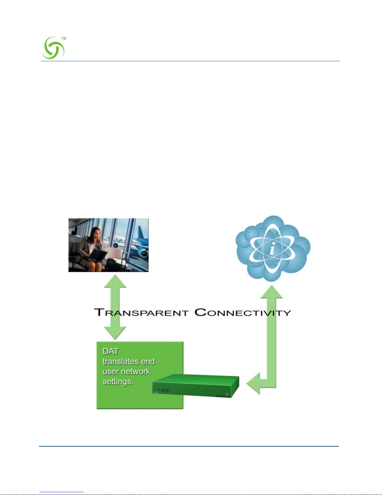
Our patented Dynamic Address Translation™ (DAT) functionality offers a true “plug and
play” solution by enabling a seamless and transparent experience and the tools to acquire new
customers on-site.
DAT greatly reduces provisioning and technical support costs and enables providers to deliver
an easy to use, customer-friendly service.
Page 17

ACCESS GATEWAY
Introduction 5
Billing Enablement
The Access Gateway supports billing plans using credit cards, scratch cards, or monthly
subscriptions, or direct billing to a hotel’s Property Management System (PMS) and can base
the billable event on a number of different parameters such as time, volume, IP address type, or
bandwidth.
Access Control and Authentication
The Access Gateway ensures that all traffic to the Internet is blocked until authentication has
been completed, creating an additional level of security in the network. Also, the Access
Gateway allows service providers to create their own unique “walled garden,” enabling users
to access only certain predetermined Web sites before they have been authenticated.
Nomadix simultaneously supports the secure browser-based Universal Access Method
(UAM), IEEE 802.1x, and Smart Clients for companies such as Adjungo Networks, Boingo
Wireless, GRIC and iPass. MAC-based authentication is also available.
Security
The patented iNAT™ (Intelligent Network Address Translation) feature creates an intelligent
mapping of IP Addresses and their associated VPN tunnels—by far the most reliable multisession VPN passthrough to be tested against diverse VPN termination servers from
companies such as Cisco, Checkpoint, Nortel and Microsoft. Nomadix’ iNAT feature allows
multiple tunnels to be established to the same VPN server, creating a seamless connection for
all users on the network.
The Access Gateway provides fine-grain management of DoS (Denial of Service) attacks
through its Session Rate Limiting (SRL) feature, and MAC filtering for improved network
reliability.
5-Step Service Branding
A network enabled with the Nomadix Access Gateway offers a 5-Step service branding
methodology for service providers and their partners, comprising:
1. Initial Flash Page branding.
2. Initial Portal Page Redirect (Pre-Authentication). Typically , this is used to redirect the user
to a venue-specific Welcome and Login page.
3. Home Page Redirect (Post-Authentication). This redirect page can be tailored to the
individual user (as part of the RADIUS Reply message, the URL is received by the NSE)
or set to re-display itself at freely configurable intervals.
Page 18

ACCESS GATEWAY
6 Introduction
4. The Information and Control Console (ICC) contains multiple opportunities for an
operator to display its branding or the branding of partners during the user’s session. As an
alternative to the ICC, a simple pop-up window provides the opportunity to display a
single logo.
5. The “Goodbye” page is a post-session page that can be defined either as a RADIUS VSA
or be driven by the Internal Web Server (IWS) in the NSE. Using the IWS option means
that this functionality is also available for other post-paid billing mechanisms (for
example, post-paid PMS).
Page 19

ACCESS GATEWAY
Introduction 7
NSE Core Functionality
Powering Nomadix’ family of Access Gateways, the Nomadix Service Engine (NSE) delivers
a full range of features needed to successfully deploy public access networks. These “core”
features solve issues of connectivity, security, billing, and roaming in a Wi-Fi public access
network.
The NSE’s core package of features includes:
Access Control
Bandwidth Management
Billing Records Mirroring
Bridge Mode
Command Line Interface
Credit Card
Dynamic Address Translation™
Dynamic Transparent Proxy
End User Licensee Count
External Web Server Mode
Home Page Redirect
iNAT™
Information and Control Console
Internal Web Server
International Language Support
IP Upsell
Logout Pop-Up Window
MAC Filtering
Multi-Level Administration Support
NTP Support
Portal Page Redirect
RADIUS Client
RADIUS-driven Auto Configuration
Page 20

ACCESS GATEWAY
8 Introduction
RADIUS Proxy
Realm-Based Routing
Remember Me and RADIUS Re-Authentication
Secure Management
Secure Socket Layer (SSL)
Secure XML API
Session Rate Limiting (SRL)
Session Termination Redirect
Smart Client Support
SNMP Nomadix Private MIB
Static Port Mapping
Tri-Mode Authentication
URL Filtering
Walled Garden
Web Management Interface
Access Control
For IP-based access control, the NSE incorporates a master access control list that checks the
source (IP address) of administrator logins. A login is permitted only if a m a tch is made wi th
the master list contained within the NSE. If a match is not made, the login is denied, even if a
correct login name and password are supplied.
The access control list supports up to 50 (fifty) entries in the form of a specific IP address or
range of IP addresses.
The NSE also offers access control based on the interface being used. This feature allows
administrators to block access from Telnet, Web Management, and FTP sources.
Administration can now be performed after unblocking the interfaces for the Subscriber side of
the NSE. The Administrative ports are configurable as well. See Establishing Secure
Administration {Access Control}.
Bandwidth Management
The NSE optimizes bandwidth by limiting bandwidth usage symmetrically or asymmetrically
on a per device (MAC address / User) basis, and manages the WAN Link traffic to provide
Page 21
ACCESS GATEWAY
Introduction 9
complete bandwidth management over the entire network. Y ou can ensure that every user has a
quality experience by placing a bandwidth ceiling on each device accessing the network, so
every user gets a fair share of the available bandwidth.
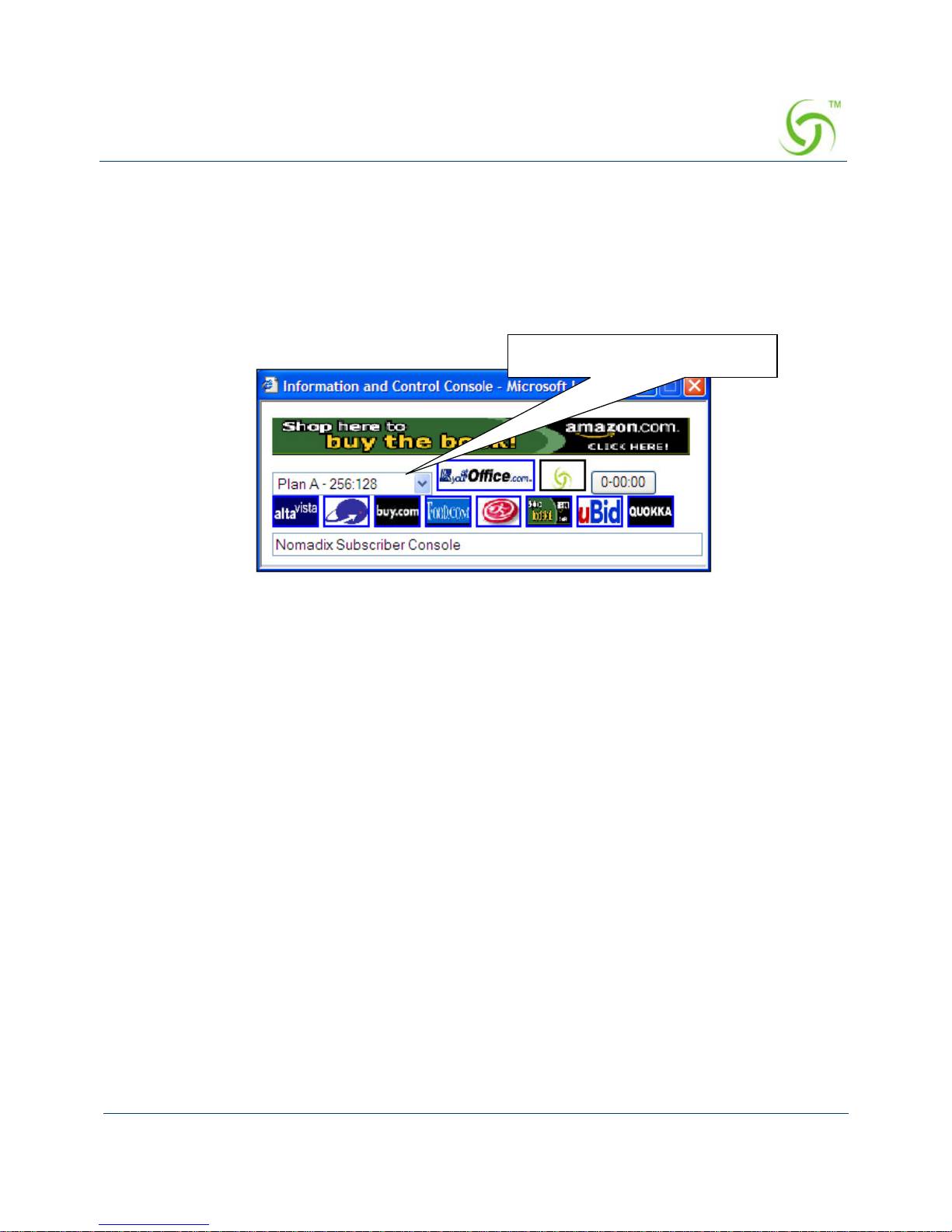
With the Nomadix ICC feature enabled, subscribers can increase or decrease their own
bandwidth and pricing plans for their service dynamically.
Billing Records Mirroring
NSE-powered devices can send copies of credit card billing records (and optionally, PMS) to
external servers that have been previously defined by system administrators. The NSE assumes
control of billing transmissions and the saving of billing records. By effectively “mirroring”
the billing data, the NSE can send copies of billing records to predefined “carbon copy”
servers. Additionally, if the primary and secondary servers are not responding, the NSE can
store up to 2,000 billing records. The NSE regularly attempts to connect with the primary and
secondary severs. When a connection is re-established (with either server), the NSE sends the
cached information to the server. Customers can be confident that their billing information is
secure and that no transaction records are lost.
Bridge Mode
This feature allows complete and unconditional access to devices. When Bridge Mode is
enabled, your NSE-powered product is effectively transparent to the network in which it is
located.
The NSE forwards any and all packets (except those addressed to the NSE network interface).
The packets are unmodified and can be forwarded in both directions. The Bridge Mode
function is a very useful feature when troubleshooting your entire network as it allows
Information and Control Console (ICC)
Bandwidth selection (pull down)
Page 22

ACCESS GATEWAY
10 Introduction
administrators to effectively “remove” your product from the network without physically
disconnecting the unit.
Command Line Interface
The Command Line Interface (CLI) is a character-based user interface that can be accessed
remotely or via a direct cable connection. Until your Nomadix product is up and running on the
network, the CLI is the Network Administrator’s window to the system. Software upgrades can
only be performed from the CLI.
See also “The Management Interfaces (CLI and Web)” on page 31.
Credit Card
The Credit Card provides a secure interface over SSL to enable billing via a credit card for
High Speed Internet Access (HSIA). This module also includes the Bill Mirror functionality
for posting of billing records to multiple sources.
See also:
“Secure Socket Layer (SSL)” on page 18.
“Billing Records Mirroring” on page 9.
Dynamic Address Translation™
Dynamic Address Translation (DAT) enables transparent broadband network connectivity,
covering all types of IP configurations (static IP, DHCP, DNS), regardless of the platform or
the operating system used—ensuring that everyone gets access to the network without the need
for changes to their computer’s configuration settings or client-side software. The NSE
supports both PPTP and IPSec VPNs in a manner that is transparent to the user and that
provides a more secure standard connection. See also, Transparent Connectivity.
Dynamic Transparent Proxy
The NSE directs all HTTP and HTTPS proxy requests through an internal proxy which is
transparent to subscribers (no need for users to perform any reconfiguration tasks). Uniquely,
the NSE also supports clients that dynamically change their browser status from non-proxy to
proxy, or vice versa. In addition, the NSE supports proxy ports 80, 800-900, 911 and 990 as
well as all unassigned ports (for example, ports above 1024), thus ensuring far fewer proxy
related support calls than competitive products.
Page 23

ACCESS GATEWAY
Introduction 11
End User Licensee Count
The NSE supports a range of simultaneous user counts depending on the Nomadix Access
Gateway you choose. In addition, depending on your platform, various user count upgrades are
available for each of our NSE-powered products that allow you to increase the simultaneous
user count.
External Web Server Mode
The External Web Server (EWS) interface is for customers who want to develop and use their
own content. It allows you to create a “richer” environment than is possible with your
product’s embedded Internal Web Server.
The advantages of using an External Web Server are:
Manage frequently changing content from one location.
Serve different pages depending on site, sub-location (for example, VLAN), and user.
Take advantage of the comprehensive Nomadix XML API to implement more
complex billing plans.
Recycle existing Web page content for the centrally hosted portal page.
If you choose to use the EWS interface, Nomadix Technical Support can provide you with
sample scripts. See also, “Contact Information” on page 311.
Home Page Redirect
The NSE supports a comprehensive HTTP redirect logic that allows network administrators to
define multiple instances to intercept the browser’s request and replace it with freely
configurable URLs.
Portal page redirect enables redirection to a portal page
before the authentication process. This
means that anyone will get redirected to a Web page to establish an account, select a service
plan, and pay for access. Home Page redirect enables redirection to a page
after the
authentication process (for example, to welcome a specific user to the service—after the user
has been identified by the authentication process. See also, Portal Page Redirect.
iNAT™
Nomadix invented a new way of intelligently supporting multiple VPN connecti ons to the
same termination at the same time (iNAT™), thus solving a key problem of many public
access networks.
Page 24

ACCESS GATEWAY
12 Introduction
Nomadix’ patented iNAT™ (intelligent Network Address Translation) feature contains an
advanced, real-time translation engine that analyzes all data packets being communicated
between the private address realm and the public address realm.
The NSE performs a defined mode of network address translation based on packet type and
protocol (for example, GRE, ISAKMP etc.). UDP packet fragmentation is supported to provide
more seamless translation engine for certificate-based VPN connections.
If address translation is needed to ensure the success of a specific application (for example,
multiple users trying to access the same VPN termination server at the same time), the packet
engine selects an IP address from a freely definable pool of publicly routable IP addresses. The
same public IP address can be used as a source IP to support concurrent tunnels to different
termination devices—offering unmatched efficiency in the utilization of costly public IP
addresses. If the protocol type can be supported wi thout the use of a public IP (for example,
HTTP, FTP), our proven Dynamic Address Translation™ functionality continues to be used.
Some of the benefits of iNAT™ include:
Improves the success rate of VPN connectivity by misconfigured users, thus reducing
customer support costs and boosting customer satisfaction.
Maintains the security benefits of traditional address translation technologies while
enabling secure VPN connections for mobile workers accessing corporate resources
from a public access location.
Dynamically adjusts the mode of address translation during the user's session,
depending on the packet type.
Supports users with static private IP addresses (for example, 192.168.x.x) or public
(different subnet) IP addresses without any changes to the client IP settings.
Dramatically heightens the reusability factor of costly public IP addresses.
Information and Control Console
The Nomadix ICC is a HTML-based pop-up window that is presented to subscribers with their
Web browser. The ICC allows subscribers to select their bandwidth and billing options quickly
Page 25

ACCESS GATEWAY
Introduction 13
and efficiently from a simple pull-down menu. For credit card accounts, the ICC displays a
dynamic “time” field to inform subscribers of the time remaining on their account.
Additionally, the ICC contains multiple opportunities for an operator to display its branding or
the branding of partners during the user’s session, as well as display advertising banners and
present a choice of redirection options to their subscribers.
See also:
5-Step Service Branding
Logout Pop-Up Window
Information and Control Console
Internal Web Server
The NSE offers an embedded Internal Web Server (IWS) to deliver Web pages stored in flash
memory. These Web pages are configurable by the system administrator by selecting various
parameters to be displayed on the internal pages. When providers or HotSpot owners do not
want to develop their own content, the IWS is the answer. A banner at the top of each IWS
page is configurable and contains the customer's company logo or any other image file they
desire.
To support PDAs and other hand-held devices, the NSE automatically formats the IWS pages
to a screen size that is optimal for the particular device being used.
See also:
5-Step Service Branding.
International Language Support.
Information and Control Console (ICC)
Page 26

ACCESS GATEWAY
14 Introduction
International Language Support
The NSE allows you to define the text displayed to your users by the IWS without any HTML
or ASP knowledge. The language you select determines the language encoding that the IWS
instructs the browser to use. See also, Internal Web Server.
The available language options are:
English
Chinese (Big 5)
French
German
Japanese (Shift_JIS)
Spanish
Other, with drop-down menu
IP Upsell
System administrators can set two different DHCP pools for the same physical LAN. When
DHCP subscribers select a service plan with a public pool address, the NSE associates their
MAC address with their public IP address for the duration of the service level agreement. The
opposite is true if they select a plan with a private pool address. This feature enables a
competitive solution and is an instant revenue generator for ISPs.
The IP Upsell feature solves a number of connectivity problems, especially with regard to
L2TP and certain video conferencing and online gaming applications.
Logout Pop-Up Window
As an alternative to the ICC, the NSE delivers a HTML-based pop-up window with the
following functions:
Provides the opportunity to display a single logo.
Displays the session’s elapsed/count-down time.
Presents an explicit Logout button.
See also, Information and Control Console.
Page 27

ACCESS GATEWAY
Introduction 15
MAC Filtering
MAC Filtering enhances Nomadix' access control technology by allowing system
administrators to block malicious users based on their MAC address. Up to 50 MAC addresses
can be blocked at any one time. See also, Session Rate Limiting (SRL).
Multi-Level Administration Support
The NSE allows you to define 2 concurrent access levels to differentiate between managers
and operators, where managers are permitted read/write access and operators are restricted to
read access only.
Once the logins have been assigned, managers have the ability to perform all write commands
(Submit, Reset, Reboot, Add, Delete, etc.), but operators cannot change any system settings.
When Administration Concurrency is enabled, one manager and three operators can access the
Access Gateway platform at any one time.
NTP Support
The NSE supports Network Time Protocol (NTP), an Internet standard protocol that assures
accurate synchronization (to the millisecond) of computer clock times in a network of
computers. NTP synchronizes the client’s clock to the U.S. Naval Observatory master clocks.
Running as a continuous background client program on a computer, NTP sends periodic time
requests to servers, obtaining server time stamps and using them to ad just the client's clock.
Portal Page Redirect
The NSE contains a comprehensive HTTP page redirection logic that allows for a page redirect
before (Portal Page Redirect) and/or after the authentication process (Home Page Redirect).
As part of the Portal Page Redirect feature, the NSE can send a defined set of parameters to the
portal page redirection logic that allows an External Web Server to perform a redirection based
on:
Access Gateway ID and IP Address
Origin Server
Port Location
Subscriber MAC address
Externally hosted RADIUS login failure page
This means that the network administrator can now perform location-specific service branding
(for example, an airport lounge) from a centralized Web server.
See also, Home Page Redirect.
Page 28

ACCESS GATEWAY
16 Introduction
RADIUS-driven Auto Configuration
Nomadix’ unique RADIUS-driven Auto Configuration functionality utilizes the existing
infrastructure of a mobile operator to provide an effortless and rapid method for configuring
devices for fast network roll-outs. Once configured, this methodology can also be effectively
used to centrally manage configuration profiles for all Nomadix devices in the public access
network.
Two subsequent events drive the automatic configuration of Nomadix devices:
1. A flow of RADIUS Authentication Request and Reply messages between the Nomadix
gateway and the centralized RADIUS server that specifies the location of the meta
configuration file (containing a listing of the individual configuration files and their
download frequency status) are downloaded from an FTP server into the flash of the
Nomadix device.
2. Defines the automated login into the centralized FTP server and the actual download
process into the flash.
Optionally, the RADIUS authentication process and FTP download can be secured by sending
the traffic through a peer-to-peer IPSec tunnel established by the Nomadix gateway and
terminated at the NOC (Network Operations Center). See also, Secure Management.
RADIUS Client
Nomadix offers an integrated RADIUS (Remote Authentication Dial-In User Service) client
with the NSE allowing service providers to track or bill users based on the number of
connections, location of the connection, bytes sent and received, connect time, etc. The
customer database can exist in a central RADIUS server, along with associated attributes for
each user. When a customer connects into the network, the RADIUS client authenticates the
customer with the RADIUS server, applies associated attributes stored in that customer's
profile, and logs their activity (including bytes transferred, connect time, etc.). The NSE's
RADIUS implementation also handles vendor specific attributes (VSAs), required by WISPs
that want to enable more advanced services and billing schemes, such as a per device/per
month connectivity fee. See also, RADIUS Proxy.
RADIUS Proxy
The RADIUS Proxy feature relays authentication and accounting packets between the parties
performing the authentication process. Different realms can be set up to directly channel
RADIUS messages to the various RADIUS servers. This functionality can be ef fectively
deployed to:
Support a wholesale WISP model directly from the edge without the need for any
centralized AAA proxy infrastructure.
Page 29

ACCESS GATEWAY
Introduction 17
Support EAP authenticators (for example, WLAN APs) on the subscriber-side of the
NSE to transparently proxy all EAP types (TLS, SIM, etc.) and to allow for the
distribution of per-session keys to EAP authenticators and supplicants.
Complementing the RADIUS Proxy functionality is the ability to route RADIUS m e ssages
depending on the Network Access Identifier (NAI). Both prefix-based (for example, ISP/
[email protected]) and suffix-based ([email protected]) NAI routing mechanisms are
supported. Together, the RADIUS Proxy and Realm-Based Routing further support the
deployment of the Wholesale Wi-Fi™ model allowing multiple providers to service one
location. See also, RADIUS Client.
Realm-Based Routing
Realm-Based Routing provides advanced NAI (Network Access Identifier) routing
capabilities, enabling multiple service providers to share a HotSpot location, further supporting
a Wi-Fi wholesale model. This functionality allows users to interact only with their chosen
provider in a seamless and transparent manner.
Remember Me and RADIUS Re-Authentication
The NSE’s Internal Web Server (IWS) stores encrypted login cookies in the browser to
remember logins, using usernames and passwords. This “Remember Me” functionality creates
a more efficient and better user experience in wireless networks.
The RADIUS Re-Authentication buffer has been expanded to 720 hours, allowing an even
more seamless and transparent connection experience for repeat users.
Secure Management
There are many different ways to configure, manage and monitor the performance and up-time
of network devices. SNMP, Telnet, HTTP and ICMP are all common protocols to accomplish
network management objectives. And within those objectives is the requirement to provide the
highest level of security possible.
While several network protocols have evolved that offer some level of security and data
encryption, the preferred method for attaining maximum security across all network devices is
to establish an IPSec tunnel between the NOC (Network Operations Center) and the edge
device (early VPN protocols such as PPTP have been widely discredited as a secure tunneling
method).
As part of Nomadix’ commitment to provide outstanding carrier-class network management
capabilities to its family of public access gateways, we offer secure management through the
NSE’ s standards-driven, peer-to-peer IPSec tunneling with strong data encryption.
Establishing the IPSec tunnel not only allows for the secure management of the Nomadix
Page 30

ACCESS GATEWAY
18 Introduction
gateway using any preferred management protocol, but also the secure management of third
party devices (for example, WLAN Access Points and 802.3 switches) on private subnets on
the subscriber side of the Nomadix gateway. See also, Defining IPSec Tunnel Settings.
T wo subsequent events drive the secure manage ment function of the Nomadix gateway and the
devices behind it:
1. Establishing an IPSec tunnel to a centralized IPSec termination server (for example, Nortel
Contivity). As part of the session establishment process, key tunnel parameters are
exchanged (for example, Hash Algorithm, Security Association Lifetimes, etc.).
2. The exchange of management traffic, either originating at the NOC or from the edge
device through the IPSec tunnel. Alternatively, AAA data such as RADIUS
Authentication and Accounting traffic can be sent through the IPSec tunnel. See also,
RADIUS-driven Auto Configuration.
The advantage of using IPSec is that all types of management traffic are supported, including
the following typical examples:
ICMP - PING from NOC to edge devices
Telnet - Telnet from NOC to edge devices
Web Management - HTTP access from NOC to edge devices
SNMP
SNMP GET from NOC to subscriber-side device (for example, AP)
SNMP SET from NOC to subscriber-side device (for example, AP)
SNMP Trap from subscriber-side device (for example, AP) to NOC
Secure Socket Layer (SSL)
This feature allows for the creation of an end-to-end encrypted link between your NSEpowered product and wireless clients by enabling the Internal Web Server (IWS) to display
pages under a secure link—important when transmitting AAA information in a wireless
network when using RADIUS.
SSL requires service providers to obtain digital certificates to create HTTPS pages.
Instructions for obtaining certificates are provided by Nomadix.
Secure XML API
XML (eXtensible Markup Language) is used by the subscriber management module for user
administration. The XML interface allows the NSE to accept and process XML commands
from an external source. XML commands are sent over the netw ork to your NSE-powered
product which executes the commands, and returns data to the system that initiated the
Page 31

ACCESS GATEWAY
Introduction 19
command request. XML enables solution providers to customize and enhance their product
installations.
This feature allows the operator to use Nomadix' popular XML API using the built-in SSL
certificate functionality in the NSE so that parameters passed between the Gateway and the
centralized Web server are secured via SSL.
Session Rate Limiting (SRL)
Session Rate Limiting (SRL) significantly reduces the risk of “Denial of Service” attacks by
allowing administrators to limit the number sessions any one user can take over a given time
period and, if necessary, then block malicious users.
Session Termination Redirect
Once connected to the public access network, the NSE will automatically redirect the customer
to a Web site for local or personalized services if the customer logs out or the customer’s
account expires while online and the goodbye page is enabled. In addition, the NSE also
provides pre- and post-authentication redirects as well as one at session termination.
Smart Client Support
The NSE supports authentication mechanisms used by Smart Clients by companies such as
Adjungo Networks, Boingo Wireless, GRIC and iPass.
SNMP Nomadix Private MIB
Nomadix’ Access Gateways can be easily managed over the Internet with an SNMP client
manager (for example, HP OpenView or Castle Rock).
To take advantage of the functionality provided with Nomadix ’ pri vate MIB (Management
Information Base), simply import the
nomadix.mib file from the Accessories CD (supplied
with the product) to view and manage SNMP objects on your product.
See also:
Using an SNMP Manager
Installing the Nomadix Private MIB
If you plan to implement XML for external billing, please contact technical
support for the XML specification of your product. Refer to “Contact
Information” on page 311.
Page 32

ACCESS GATEWAY
20 Introduction
Static Port Mapping
This feature allows the network administrator to setup a por t map pi n g scheme that forwards
packets received on a specific port to a particular static IP (typically private and misconfigured)
and port number on the subscriber side of the NSE. The advantage for the network
administrator is that free private IP addresses can be used to manage devices (such as Access
Points) on the subscriber side of the NSE without setting them up with Public IP addresses.
Tri-Mode Authentication
The NSE enables multiple authentication models providing the maximum amount of flexibility
to the end user and to the operator by supporting any type of client entering their network and
any type of business relationship on the back end. For example, in addition to supporting the
secure browser-based Universal Access Method (UAM) via SSL, Nomadix is the only
company to simultaneously support port-b ased authentication using IEEE 802.1x and
authentication mechanisms used by Smart Clients. MAC-based authentication is also available.
See also:
Access Control and Authentication
Smart Client Support
URL Filtering
The NSE can restrict access to specified Web sites based on URLs defined by the system
administrator . URL filtering will block access to a list of sites and/or domains entered by the
administrator using the following three methods:
Host IP address (for example, 1.2.3.4).
Host DNS name (for example, www.yahoo.com).
DNS domain name (for example, *.yahoo.com, meaning all sites under the
yahoo.com hierarchy, such as finance.yahoo.com, sports.yahoo.com, etc.).
The system administrator can dynamically add or remove up to 300 specific IP addresses and
domain names to be filtered for each property.
Walled Garden
The NSE provides up to 300 IP passthrough addresses (and/or DNS entries), allowing you to
create a “Walled Garden” within the Internet where unauthenticated users can be granted or
denied access to sites of your choosing.
Page 33

ACCESS GATEWAY
Introduction 21
Web Management Interface
Nomadix’ Access Gateways can be managed remotely via the built-in Web Management
Interface where various levels of administration can be established. See also, Using the Web
Management Interface (WMI).
Page 34

ACCESS GATEWAY
22 Introduction
Optional NSE Modules
Hospitality Module
The optional Hospitality Module provides the widest range of Property Management System
(PMS) interfaces to enable in-room guest billing for High Speed Internet Access (HSIA)
service. This module also includes 2-Way PMS interface capability for in-room billing in a W iFi enabled network. In addition, the Hospitality Module includes the Bill Mirror functionality
for posting of billing records to multiple sources. With this module, the NSE also supports
billing over a TCP/IP connection to select PMS interfaces.
PMS Integration
By integrating with a hotel’s PMS, your NSE-powered product can post charges for Internet
access directly to a guest’s hotel bill. In this case, the guest is billed only once. The NSE
outputs a call accounting record to the PMS system whenever a subscriber purchases Internet
service and decides to post the charges to their room. Nomadix’ Access Gateways are equipped
with a serial PMS interface port to facilitate connectivity with a customer’s Property
Management System.
High Availability Module
The optional High Availability Module offers enhanced network uptime and service
availability when delivering high-quality Wi-Fi service by providing Fail-Over functionality .
This module allows a secondary Nomadix Access Gateway to be placed in the network that can
take over if the primary device fails, ensuring Wi-Fi service remains uninterrupted.
Your product license may not support this feature.
Some Property Management Systems may require you to obtain a license before
integrating the PMS with the Access Gateway. Check with the PMS vendor.
Your product license may not support this feature.
Page 35
ACCESS GATEWAY
Introduction 23
Network Architecture (Sample)
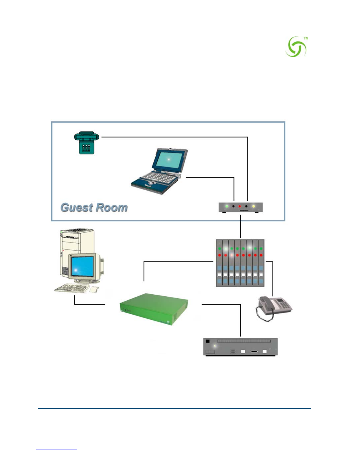
The Access Gateway can be deployed effectively in a variety of wireless and wired broadband
environments where there are many users—usually mobile—who need high speed access to
the Internet.
The following example shows a potential Hospitality application:
Phone
Laptop
DSL Modem
PMS
DSLAM
PBX
Router
AG
Page 36

ACCESS GATEWAY
24 Introduction
Online Help (WebHelp)
The Access Gateway incorporates an online Help system called “WebHelp” which is
accessible through the Web Management Interface (when a remote Internet connection is
established following a successful installation). WebHelp can be viewed on any platform (for
example, Windows, Macintosh, or UNIX-based platforms) using either Internet Explorer or
Netscape Navigator (see note).
WebHelp is useful when you have an Internet connection to the Access Gateway and you want
to access information quickly and efficiently. It contains all the information you will find in
this User Guide.
For more information about WebHelp and other online documentation resources, go to “Online
Documentation and Help” on page 35.
Notes, Cautions, and Warnings
The following formats are used throughout this User Guide:
General notes and additional information that may be useful are indicated with a
Note.
Cautions and warnings are indicated with a Caution. Cautions and warnings
provide important information to eliminate the risk of a system malfunction or
possible damage.
Page 37

ACCESS GATEWAY
1
Installing the Access Gateway 25
Installing the Access Gateway
This section provides installation instructions for the hardware and software components of the
Access Gateway. It also includes an overview of the management interface, some helpful hints
for system administrators, a Quick Reference Guide, and procedures for the following tasks:
“Unpacking the Access Gateway” on page 26
“Powering Up the System” on page 28
“Logging In to the Command Line Interface” on page 29
“Establishing the Start Up Configuration” on page 36
“Logging Out and Powering Down the System” on page 44
“Connecting the Access Gateway to the Customer ’s Network” on page 44
“Establishing the Basic Configuration for Subscribers” on page 45
“Archiving Your Configuration Settings” on page 51
“Installing the Nomadix Private MIB” on page 52
Nomadix Access Gateway
Once you have installed your Access Gateway and established the configuration
settings, you should write the settings to an archive file. If you ever experience
problems with the system, your archived settings can be restored at any time. See
“Archiving Your Configuration Settings” on page 51.
Page 38

ACCESS GATEWAY
26 Installing the Access Gateway
Unpacking the Access Gateway
When you unpack the Access Gateway, you will find the following items in the carton:
Item Qty
Access Gateway module 1
Cable – power cord (US or European) 1
Cable – serial, DB9 female to DB9 female (6ft length) Null Modem (NM) or
DB9 female to RJ45 (6ft length) Null Modem (NM)
1
Cable – CATS5, standard (7 ft. length) 1
Cable – CATS5, crossover (7 ft. length) 1
Screw 10-32 X 1/2 PH with internal washer 4
Screw 4-40 5/16” flathead 100 deg 8
Plastic bumper feet 4
Universal mounting bracket 2
Quick Start Guide 1
“Accessories” CD-ROM (containing this User Guide, README file, NOMADIX
Enterprise MIB file, and any other useful accessories)
1
Customer letter 1
End User License Agreement (EULA) 1
Packing materials (polystyrene end caps) 2
Page 39
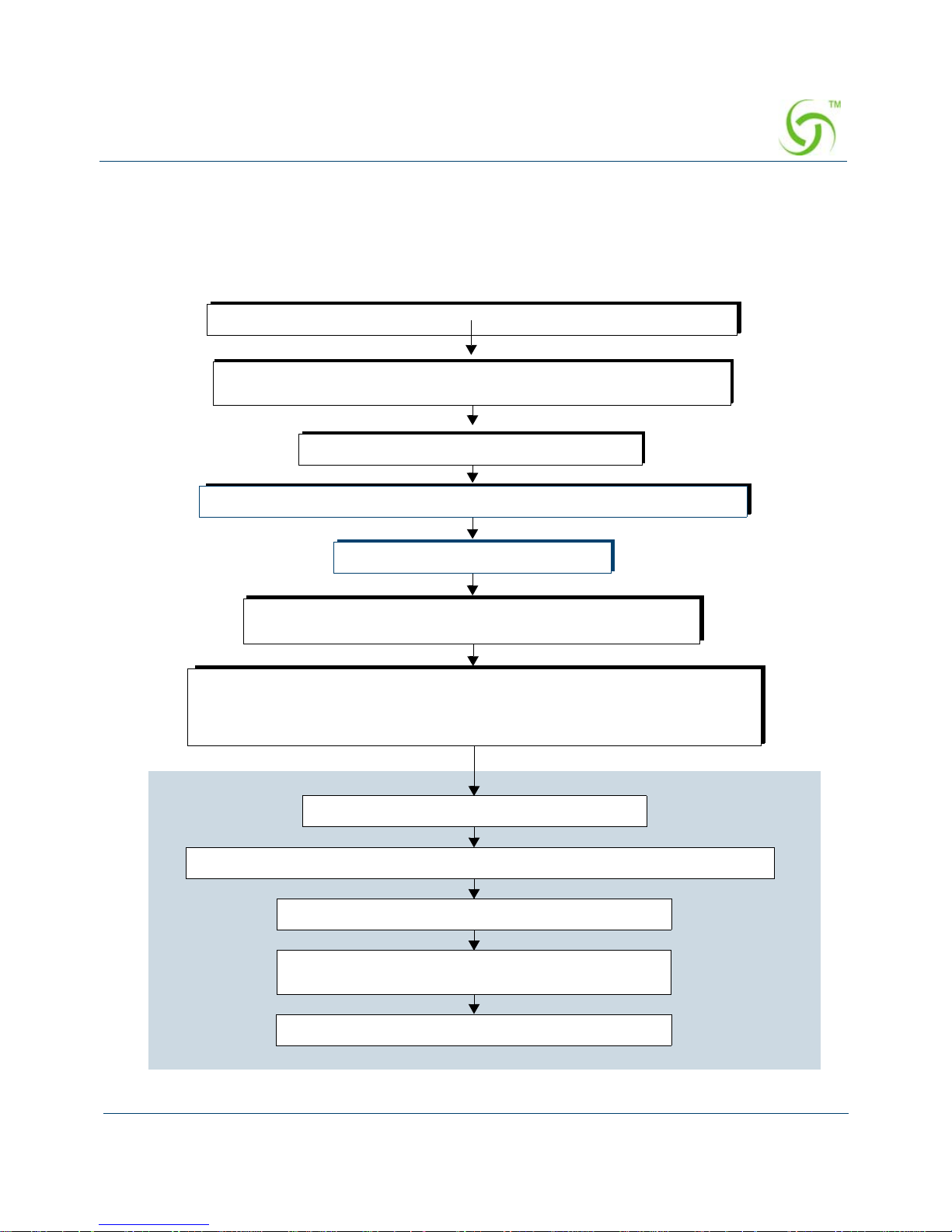
ACCESS GATEWAY
Installing the Access Gateway 27
Installation Workflow
The following flowchart illustrates the steps that are required to install and configure your
Access Gateway successfully. Review the installation workflow before attempting to install
the Access Gateway on the customer’s network.
Place the AG on a flat and stable work surface and connect the power cord.
Start a HyperTerminal session to communicate with the AG via the serial port.
Power up your computer and turn on the AG.
Log in to the Command Line Interface.
When prompted, configure your AG’s IP, DNS, and Location
settings. The AG will then prompt you to reboot the system.
Connect the AG to the customer’s network.
Power up the AG and log in via a Telnet session or the Web Management Interface.
Set the basic configuration parameters for subscribers.
Network
Connect the AG to a “live” network. Use the DB9 serial cable (6 ft. length)
between the AG’s serial port and your computer.
Export your configuration settings to an archive file.
The AG is now ready for administrators to add, delete, or
change unique subscriber profiles.
When prompted, accept to the Nomadix End User License Agreement (EULA). You
must accept the EULA before the AG can connect with the Nomadix License Key
Server. When the key is successfully received from the server, your AG will reboot.
You can now power down and connect the AG to the customer’s network.
Page 40
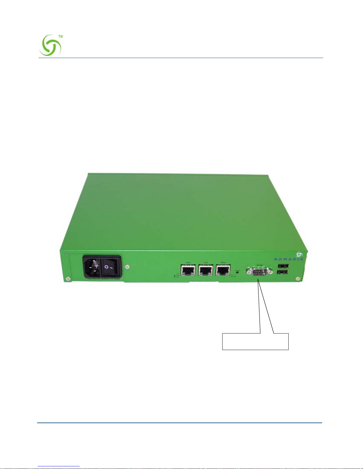
ACCESS GATEWAY
28 Installing the Access Gateway
Powering Up the System
Use this procedure to establish a direct cable connection between the Access Gateway and your
laptop computer, and to power up the system.
1. Place the Access Gateway on a flat and stable work surface.
2. Connect the power cord.
3. Connect the DB9 serial cable between the Access Gateway’ s “serial port” or “front Access
RJ45 port” and your computer.
4. Turn on your computer and allow it to boot up.
5. Turn on the Access Gateway.
Connect the serial
cable here
(On other platforms,
connection may be via
front-access RJ45 port).
Page 41

ACCESS GATEWAY
Installing the Access Gateway 29
Logging In to the Command Line Interface
Use this procedure to initialize the system and log in to the Access Gateway’s Command Line
Interface (CLI). The character-based CLI is used at initial start-up.
1. Start a HyperTerminal™ session to connect to the Access Gateway. Use the following
HyperTerminal settings:
2. When connected to the Access Gateway, a login prompt appears on your screen.
The default login user name is “admin.” The password is “admin.” Login names and
passwords are case-sensitive.
3. Enter admin when prompted for a user name and password. The Access Gateway Menu
appears when you have logged in to the Access Gateway’s management interface
successfully. If this is an initial installation which requires the Access Gateway to receive
Bits per second 9600
Data bits 8
Parity None
Stop bits 1
Flow control None
Page 42
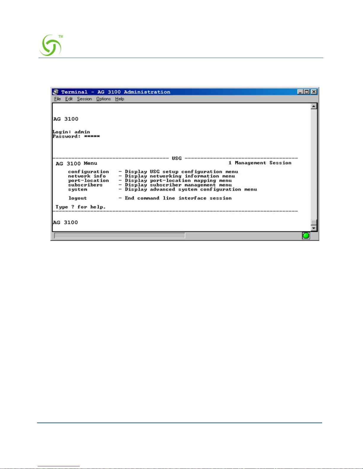
ACCESS GATEWAY
30 Installing the Access Gateway
a license key from the Nomadix License Key Server, you must accept the Nomadix End
User License Agreement (EULA)..
.
Page 43

ACCESS GATEWAY
Installing the Access Gateway 31
The Management Interfaces (CLI and Web)
Until the unit is installed on the customer’ s network and a remote connection is established, the
CLI is the administrator’s window to the system. This is where you establish all the Access
Gateway start-up configuration parameters, depending on the customer’s network architecture.
The Access Gateway Menu is your starting point. From here, you access all the system
administration items from the 5 (five) primary menus available:
Configuration
Network Info
Port-location
Subscribers
System
Making Menu Selections and Inputting Data with the CLI
The CLI is character-based. It recognizes the fewest unique characters it needs to correctly
identify an entry. For example, in the Access Gateway Menu you need only enter
c to access
the Configuration menu, but you must enter
su to access the Subscribers menu and sy to
access the System menu (because they both start with the letter “s”).
You may also do any of the following:
Enter b (back) or press Esc (escape) to return to a previous menu.
Press Esc to abort an action at any time.
Press Enter to redisplay the current menu.
Press ? at any time to access the CLI’s Help screen.
The Access Gateway supports various methods for managing the system
remotely. These include, an embedded graphical Web Management Interface
(WMI), an SNMP client, or Telnet. However, until the unit is installed and
running, system management is performed from the Access Gateway’s embedded
CLI via a direct serial cable connection. The CLI can also be accessed remotely.
Although the basic functional elements are the same, the CLI and the WMI have
some minor content and organizational differences. For example, in the WMI the
“subscribers” menu is divided into “Subscriber Administration” and
“Subscriber Interface.” See also, “Menu Organization (Web Management
Interface)” on page 32.
Page 44

ACCESS GATEWAY
32 Installing the Access Gateway
When using the CLI, if a procedure asks you to “enter sn,” this means you must type sn and
press the
Enter key. The system does not accept data or commands until you hit the Enter key.
Menu Organization (Web Management Interface)
When you have successfully installed and configured the Access Gateway from the CLI, you
can then access the Access Gateway from its embedded Web Management Interface (WMI).
The WMI is easier to use (point and click) and includes some items not found in the CLI. You
can use either interface, depending on your preference.
For a complete description of all features available in the WMI, see “Using the Web
Management Interface (WMI)” on page 54.
The following “composite” screen shows how the Access Gateway’ s WMI menus (folders) are
organized (shown here side-by-side for clarity and space). See also, About Your Product
License.
Page 45
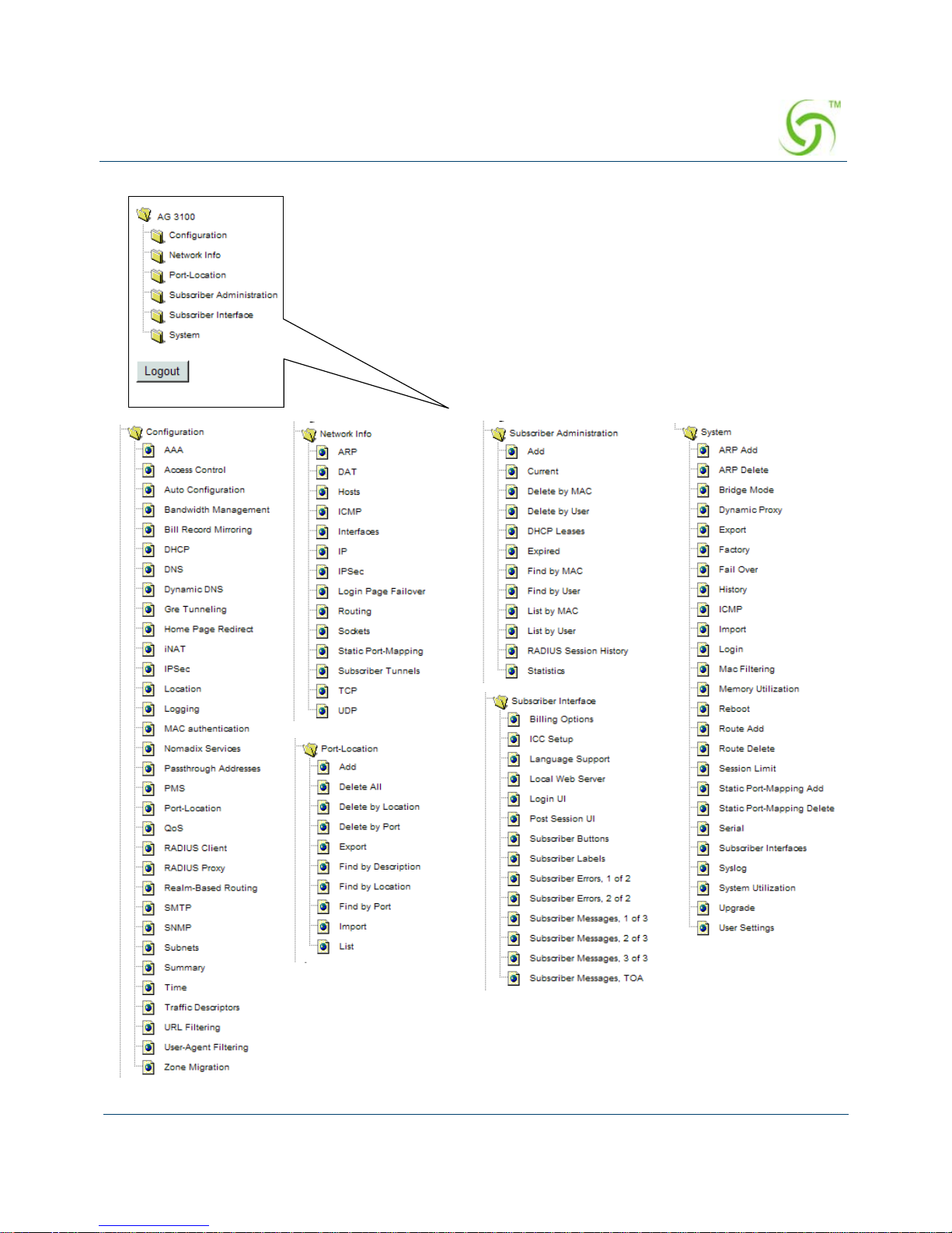
ACCESS GATEWAY
Installing the Access Gateway 33
Note: Your browser preferences or
Internet options should be set to
compare loaded pages with cached
pages.
Page 46

ACCESS GATEWAY
34 Installing the Access Gateway
Inputting Data – Maximum Character Lengths
The following table details the maximum allowable character lengths when inputting data:
Data Field Max. Characters
All Messages (billing options) 72
All Messages (subscriber error messages) 72
All Messages (subscriber login UI) 72
All Messages (subscriber “other” messages) 72
Description of Service (billing options Plan) 140
Home Page URL 237
Host Name and Domain Name (DNS settings) 64
IP / DNS Name (passthrough addresses) 237
Label (billing options plan) 16
Location settings (all fields) 99
Partner Image File Name 12
Password (adding subscriber profiles) 128
Port Description (finding ports by description) 63
Redirection Frequency (in minutes) 2,147,483,647
(recommend 3600)
Reservation Number 24
Username (adding subscriber profiles) 96
Valid SSL Certificate DNS Name 64
Page 47
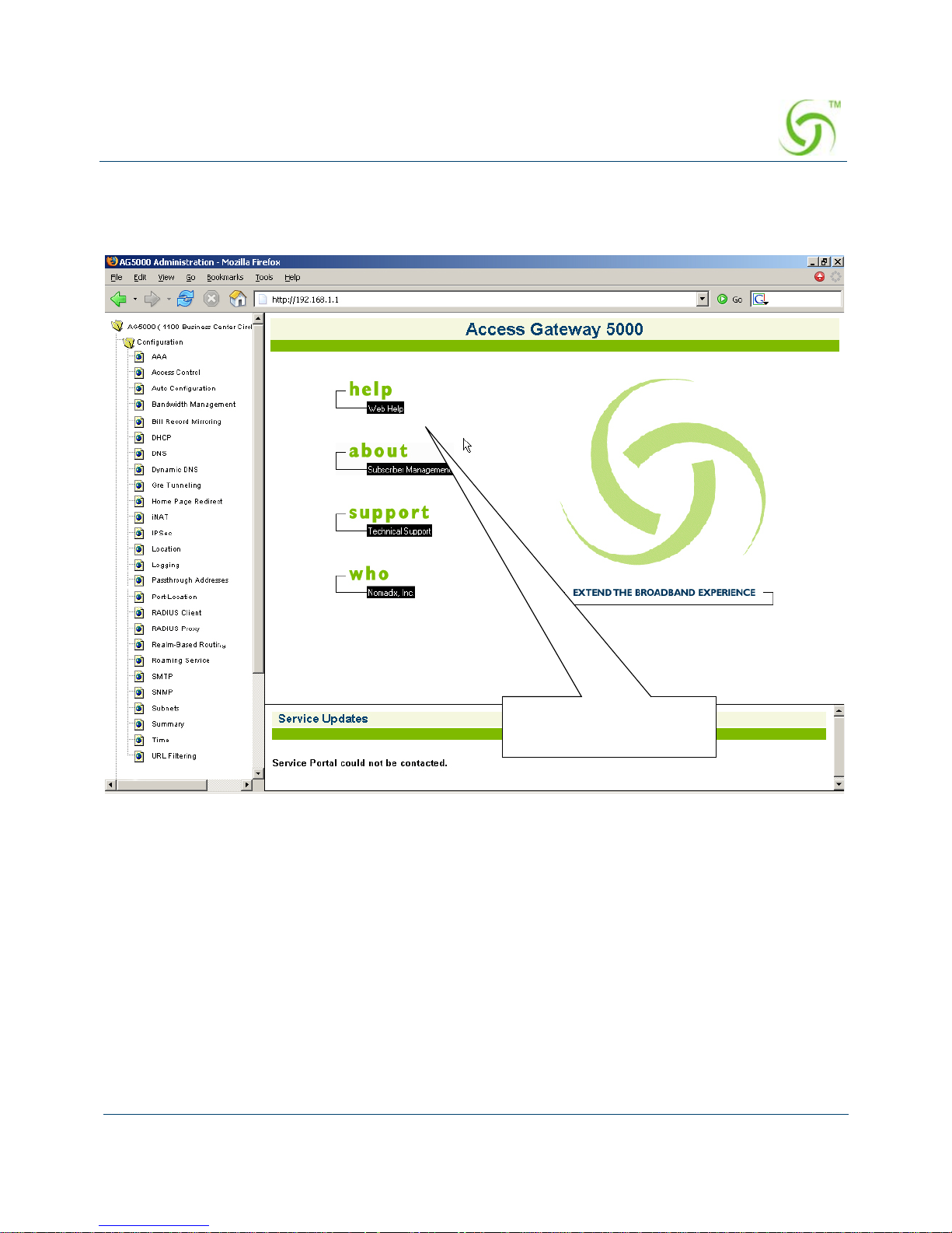
ACCESS GATEWAY
Installing the Access Gateway 35
Online Documentation and Help
The W eb Management Interface (WMI) incorporates an online help system which is accessible
from the main window.
Other online documentation resources, available from our corporate Web site
(www.nomadix.com), include a full PDF version of this User Guide (viewable with Acrobat™
Reader), white papers, technical notes, and business cases. The PDF version of this User Guide
and associated README files are also available on the “Accessories” CD-ROM supplied with
your Access Gateway.
Click here to access the
online Help system
Page 48

ACCESS GATEWAY
36 Installing the Access Gateway
Quick Reference Guide
This manual contains a “Quick Reference Guide” on page 36 which provides information to
help you navigate and use the management interfaces (CLI and Web) quickly and efficiently. It
also contains the product specifications, a listing of the factory default settings, sample log
reports, listings of commands (by menu and alphabetical), HyperTerminal settings, and some
common keyboard shortcuts.
Establishing the Start Up Configuration
The CLI allows you to administer the Access Gateway’s start-up configuration settings.
The start up configuration must be established before connecting the Access Gateway to a
customer’s network. The “start up” configuration settings include:
Assigning Login User Names and Passwords – You must assign a unique login user
name and password that enables you to administer and manage the Access Gateway
securely.
Setting the SNMP Parameters (optional) – The SNMP (Simple Network Management
Protocol) parameters must be established before you can use an SNMP client (for
example, HP OpenView) to manage and monitor the Access Gateway remotely.
Enabling the Logging Options (recommended) – Servers must be assigned and set up
if you want to create system and AAA (billing) log files, and retrieve error messages
generated by the Access Gateway.
When establishing the start-up configuration for a new installatio n, you are
connected to the Access Gateway via a direct serial connection (you do not have
remote access capability because the Access Gateway is not yet configured or
connected to a network). Once the installation is complete (see “Installation
Workflow” on page 27) and the system is successfully configured, you will have
the additional options of managing the Access Gateway remotely from the
system’s Web Management Interface, an SNMP client manager of your choice, or
a simple Telnet interface.
User names and passwords are case-sensitive.
Page 49

ACCESS GATEWAY
Installing the Access Gateway 37
Assigning the Location Information and IP Addresses:
Assigning the Network Interface IP Address - This is the public IP
address that allows administrators and subscribers to see the Access Gateway
on the network. Use this address when you need to make a network connection
with the Access Gateway.
Assigning the Subnet Mask – The subnet mask defines the number of IP
addresses that are available on the routed subnet where the Access Gateway is
located.
Assigning the Default Gate w ay IP Add res s – This is the IP address of
the router that the Access Gateway uses to transmit data to the Internet.
Assigning Login User Names and Passwords
When you initially powered up the Access Gateway and logged in to the Management
Interface, the default login user name and password you used was “admin.” The Access
Gateway allows you to define 2 concurrent access levels to differentiate between managers and
operators, where managers are permitted read/write access and operators are restricted to read
access only . Once the logins have been assigned, ma nagers have the ability to perform all write
commands (Submit, Reset, Reboot, Add, Delete, etc.), but operators cannot change any system
settings. When Administration Concurrency is enabled, one manager and three operators can
access the Access Gateway at any one time (the default setting for this feature is “disabled”).
1. Enter sy (system) at the Access Gateway Menu. The System menu appears.
2. Enter lo (login).
The system prompts you for the current login. If this is the first time you are changing the
login parameters since initializing the Access Gateway, the default login name and
password is “admin.”
3. When prompted, confirm the current login parameters and enter new ones.
Sample Screen Response:
System>lo
Enable/Disable Administration Concurrency [disabled]: e
Current login: admin
Current password: *****
Enter new manager login: newmgr
Enter new password: *******
Retype new password: *******
The system accepts up to 11 characters (any character type) for user names and
passwords. All user names and passwords are case-sensitive.
Page 50

ACCESS GATEWAY
38 Installing the Access Gateway
The administrative login and password were changed
Enter new operator login: newop
Enter new operator password: *****
Retype new operator password: *****
The operator login and password were changed
Enter RADIUS remote test login: rad
Enter new RADIUS remote test password: *****
Retype new RADIUS remote test password: *****
The RADIUS remote test login and password were changed
You must use the new login user name(s) and password(s) to access the system.
Setting the SNMP Parameters (optional)
You can address the Access Gateway using an SNMP client manager (for example, HP
OpenView). SNMP is the standard protocol that regulates network management over the
Internet. To do this, you must set up the SNMP communities and identifiers. For more
information about SNMP, see “Using an SNMP Manager” on page 54.
1. Enter c (configuration) at the Access Gateway Menu. The Configuration menu appears.
2. Enter sn (snmp).
3. Enable the SNMP daemon, as required. The system displays any existing SNMP contact
information and prompts you to enter new information. If this is the first time you have
initialized the SNMP command since removing the Access Gateway from its box, the
system has no information to display (there are no defaults).
4. Enter the SNMP parameters (communities and identifiers). The SNMP parameters include
your contact information, the get/set communities, and the IP address of the trap recipient.
Your SNMP manager needs thi s information to enable network management over the
Internet.
5. If you enabled the SNMP daemon, you must reboot the system for your changes to take
effect. In this case, enter
y (yes) to reboot your Access Gateway.
Sample Screen Response:
Configuration>sn
Enable the SNMP Daemon? [Yes]:
Enter new system contact: [email protected]
[Nomadix, Newbury Park, CA]
If you want to use SNMP, you must manually turn on SNMP.
Page 51

ACCESS GATEWAY
Installing the Access Gateway 39
Enter new system location: Office, Newbury Park, CA
Enter read/get community [public]:
Enter write/set community [private]:
Enter IP of trap recipient [0.0.0.0]: 10.11.12.13
SNMP Daemon: Enabled
System contact: [email protected]
System location: Office, Newbury Park, CA
Get (read) community: public
Set (write) community: private
Trap recipient: 10.11.12.13
Reboot to enable new changes? [yes/no] y
Rebooting...
You can now address the Access Gateway using an SNMP client manager.
Enabling the Logging Options (recommended)
System logging creates log files and error messages generated at the system level. AAA
logging creates activity log files for the AAA (Authentication, Authorization, and Accounting)
functions. You can enable either of these options.
When system logging is enabled, the standard SYSLOG protocol (UDP) is used to send all
message logs generated by the Access Gateway to the specified server.
1. Enter log (logging) at the Configuration menu. The system displays the current logging
status (enabled or disabled).
2. Enable or disable the system and/or AAA logging options, as required. If you enable
either option, go to Step 3, otherwise logging is disabled and you can terminate this
procedure.
3. Assign a valid ID number (0-7) to each server.
4. Enter the IP addresses to identify the location of the system and AAA SYSLOG servers on
the network (the default for both is 0.0.0.0).
When logging is enabled, log files and error messages are sent to these servers for future
retrieval. To see sample reports, go to “Sample SYSLOG Report” on page 278 and
“Sample AAA Log” on page 277.
Although the AAA and billing logs can go to the same server, we recommend that
they have their own unique server ID number assigned (between 0 and 7). When
managing multiple properties, the properties ar e identified in the log files by their
IP addresses.
Page 52

ACCESS GATEWAY
40 Installing the Access Gateway
Sample Screen Response:
Configuration>log
Enable/disable System Log [disabled ]: enable
Enter System Log Number (0-7) [0 ]: 2
Enter System Log Filter
0: Emergency
1: Alert
2: Critical
3: Error
4: Warning
5: Notice
6: Info
7: Debug
Select an option from above [7]: 7
Enter System Log Server IP [255.255.255.255]: 10.10.10.10
Enable/disable System Log Save to file [disabled ]: enable
Enable/disable AAA Log [disabled ]: enable
Enter AAA Log Number (0-7) [0 ]: 2
Enter AAA Log Filter
0: Emergency
1: Alert
2: Critical
3: Error
4: Warning
5: Notice
6: Info
7: Debug
Select an option from above [7]: 7
Enter AAA Log Server IP [255.255.255.255]: 10.10.10.10
Enable/disable AAA Log Save to file [disabled ]: enable
Enable/disable RADIUS History Log [disabled ]: enable
Enter RADIUS History Log Number (0-7) [0 ]: 2
Enter RADIUS History Log Filter
0: Emergency
1: Alert
2: Critical
3: Error
4: Warning
5: Notice
6: Info
Page 53

ACCESS GATEWAY
Installing the Access Gateway 41
7: Debug
Select an option from above [6]: 7
Enter RADIUS History Log Server IP [255.255.255.255]: 10.10.10.10
Enable/disable RADIUS History Log Save to file [disabled ]: enable
Enable/disable System Report Log [disabled ]: enable
Enter System Report Log Number (0-7) [0 ]: 2
Enter System Report Log Server IP [255.255.255.255]: 10.10.10.10
Enter System Report Log interval (minutes) [0]: 5
Enable/disable Tracking Log [disabled ]: enable
Enter Tracking Log Number (0-7) [0 ]: 2
Enter Tracking Log Server IP [255.255.255.255]: 10.10.10.10
Enable/disable Tracking Log Save to file [disabled ]:
Enable/Disable Name Reporting [disabled ]: enable
Enable/Disable Port Reporting [disabled ]: enable
Enable/Disable Location Reporting [disabled ]: enable
Enable/Disable 500th Packet Count Reporting [disabled ]: enable
System Log Enabled
System Log Number 2
System Log Filter 7
System Log Server IP 10.10.10.10
System Log Save to file Enabled
AAA Log Enabled
AAA Log Number 2
AAA Log Filter 7
AAA Log Server IP 10.10.10.10
AAA Log Save to file Enabled
RADIUS History Log Enabled
RADIUS History Log Number 2
RADIUS History Log Filter 7
RADIUS History Log Server IP 10.10.10.10
RADIUS History Log Save to file Enabled
System Report Log Enabled
System Report Log Number 2
System Report Log Server IP 10.10.10.10
System Report Log Interval (in minutes) 5
Tracking Log Enabled
Tracking Log Number 2
Tracking Log Server IP 10.10.10.10
Tracking Log Save to file Disabled
Tracking Name Reporting Enabled
Page 54

ACCESS GATEWAY
42 Installing the Access Gateway
Tracking Port Reporting Enabled
Tracking Location Reporting Enabled
Tracking Report every 500th packet Enabled
WARNING: Communication between the gateway and the syslog server may need to be
secured to comply with local laws. Consider routing communication through an IPSec tunnel.
Configuration>
Assigning the Location Information and IP Addresses
The “location” command in the Configuration menu establishes the Access Gateway’s location
settings, the network interface IP address, the subnet mask, and the default gateway IP address.
All of these Access Gateway “location” parameters must be set up as part of the system’s start
up configuration (otherwise the Access Gateway will not be “visible” on the network).
1. Enter c (configuration) at the Access Gateway Menu. The Configuration menu appears.
2. Enter loc (set Location options). The system displays the Company Name. If the name
displayed is not correct (or no name is entered), enter it now.
3. When prompted, enter the company’s address (line by line - 6 lines).
4. When prompted, enter a valid email address for this company.
The system now displays the current network interface IP address (the default address is
10.0.0.10) and prompts you for a valid address. The network interface IP address is the
public IP address that allows administrators to see the Access Gateway on the network.
Use this address when you need to make a network connection with the Access Gateway.
5. When prompted, enter a valid network interface IP address.
The IP addresses from subscribers that are on a subnet different from the Access Gateway
(for example, misconfigured) are translated by Nomadix’ Dynamic Address Translation
(DAT).
6. Enter a valid subnet mask.
After assigning the subnet mask, the system displays the current default gateway IP
address (the factory default is 10.0.0.1). This is the IP address of the router that the Access
Gateway uses to transmit data to the Internet.
7. Enter a valid default gateway IP address.
8. After establishing all “Location” settings, you must reboot the Access Gateway for your
changes to take effect.
The network interface address must be on the same subnet.
Page 55

ACCESS GATEWAY
Installing the Access Gateway 43
Sample Screen Response:
Configuration>loc
Please enter your company name [companyname]: newname
Please enter your site name [sitename]: Coffee House
Please enter your address <Line 1> [line1address]: newline1
<Line 2> [line2address]: newline2
<City> [city]: newcity
<State> [state]: newstate
<Zip/Postal Code> [zip]: newzip
<Country> [country]: newcountry
Please enter your email address [[email protected]]: [email protected]
Please select the venue type that most reflects your location
1. Apartment
2. Bar/Coffeeshot/Restaurant
3. Convention Center
4. Corporate Guest Access
5. Education
6. Hospitality
7. Marina/Camp Ground
8. Public Space
9. Public Transport
10. Airport
11. Truckstop / Rest Area
12. Car Rental Facility
13. Club
14. Health Club
15. Bar
16. Retail Business
17. Marina
18. Arena
19. Theatre
20. Metro Area / HotZone
21. Indoor Public Space / Hospital / Museum / Library
22. Gas Station
23. Resort
24. Lab / T est
25. Other
Please enter a number from the above list [ 1]:
Select Network Interface Configuration Mode:
0 - Static
1 - DHCP Client
2 - PPPoE Client
Select the Network Interface Configuration Mode [0]:
Page 56

ACCESS GATEWAY
44 Installing the Access Gateway
Enter network interface IP [ ]:
Enter subnet mask [ ]:
Enter default gateway IP [ ]:
Please enter your ISO country code [US]: US
Please enter your phone country code [1]: 1
Please enter your calling area code [818]: 818
Please enter your network SSID/Zone [ ]: samplezonename
The system must be reset to function properly. Reboot? [yes/no]: y
Your new settings are displayed and the Access Gateway reboots. When the system
restarts, the Telnet interface is enabled (based on your new configuration settings which
are saved to the Access Gateway’s on-board flash memory).
Go to “Logging Out and Powering Down the System” on page 44.
Logging Out and Powering Down the System
Use this procedure to log out and power down the Access Gateway.
1. Enter l (logout) at the Access Gateway Menu. Yo ur serial session closes automatically.
2. Turn off the Access Gateway and disconnect the power cord.
3. Disconnect the serial cable between the Access Gateway and your computer.
Connecting the Access Gateway to the Customer’s Network
Use this procedure to connect the Access Gateway to the customer’s network (after the start up
configuration parameters have been established).
1. Choose an appropriate physical location that allows a minimum clearance of 4cm either
side of the unit (for adequate airflow).
2. Connect the Access Gateway to the router, then connect the Access Gateway to the
customer’s subscriber port.
Start up configuration is now complete; however, before connecting the Access
Gateway to the customer’s network, you must power down the system.
Page 57
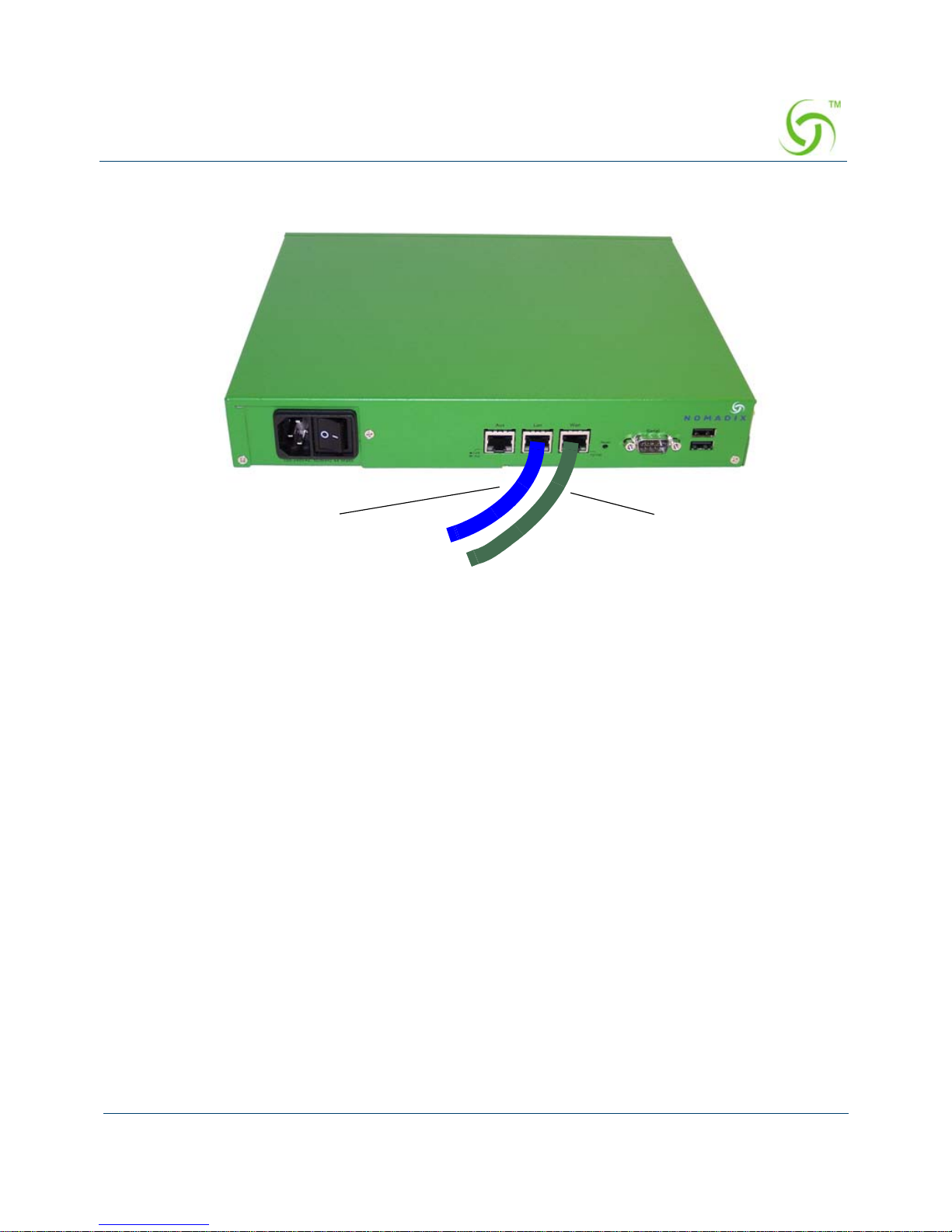
ACCESS GATEWAY
Installing the Access Gateway 45
3. Connect the power cord and turn on the Access Gateway.
4. Go to “Establishing the Basic Configuration for Subscribers” on page 45.
Establishing the Basic Configuration for Subscribers
When you have successfully established the start up configuration and installed the uni t onto
the customer’s network, connect to the Access Gateway via Telnet. You must now set up the
basic configuration parameters for subscribers, including:
Setting the DHCP Options – DHCP (Dynamic Host Configuration Protocol) allows
you to assign IP addresses automatically (to subscribers who are DHCP enabled). The
Access Gateway can “relay” the service through an external DHCP server or it can be
configured to act as its own DHCP server.
Setting the DNS Options – DNS (Domain Name System) allows subscribers to enter
meaningful URLs into their browsers (instead of complicated numeric IP addresses).
DNS converts the URLs into the correct IP addresses automatically.
Setting the DHCP Options
When a device connects to the network, the DHCP server assigns it a “dynamic” IP address for
the duration of the session. Most users have DHCP capability on their computer. To enable this
service on the Access Gateway, you can either enable the DHCP relay (routed to an external
DHCP server IP address), or you can enable the Access Gateway to act as its own DHCP
To Network
To Subscribers
Rear View
Page 58
ACCESS GATEWAY
46 Installing the Access Gateway
server. In both cases, DHCP functionali ty is necessary if you want to automatically assign IP
addresses to subscribers.
1. Enter c (configuration) at the Access Gateway Menu. The Configuration menu appears.
2. Enter dh (dhcp).
3. Follow the on-screen instructions to set up your DHCP options. For example:
Sample Screen Response:
Configuration>dh
Enable/Disable IP Upsell [disabled ]:
Enable/Disable DHCP Relay [disabled ]:
Enable/Disable DHCP Server [enabled ]:
Enable/Disable Subnet-based DHCP Service [disabled
Enable/Disable Forwarded DHCP Clients [disabled ]:
IP Upsell Disabled
DHCP Relay Disabled
External DHCP Server IP 0.0.0.0
DHCP Relay Agent IP 0.0.0.0
DHCP Server Enabled
DHCP Server Subnet-based Disabled
Forwarded DHCP Clients Disabled
The Access Gateway’s adaptive configuration technology provides Dynamic
Address Translation (DAT) functionality. DAT is automatically configured to
facilitate “plug-and-play” access to subscribers who are misconfigured with
static (permanent) IP addresses, or subscribers that do not have DHCP capability
on their computers. DAT allows all users to obtain network access, regardless of
their computer’s network settings.
By default, the Access Gateway is configured to act as its own DHCP server and
the relay feature is “disabled.”. Please verify that your DHCP Server supports
DHCP packets before enabling the relay. Not all devices containing DHCP
servers (for example, routers) support DHCP Relay functionality.
When assigning a DHCP Relay Agent IP address for the DHCP Relay, ensure
that the IP address you use does not conflict with devices on the network side of
the Access Gateway.
Although you cannot enable the DHCP relay and the DHCP service at the
same time, it is possible to “disable” both functions from the Command Line
Interface. In this case, a warning message informs you that no DHCP services
are available to subscribers.
Page 59
ACCESS GATEWAY
Installing the Access Gateway 47
Server-IP Server-Netmask Start-IP End-IP Lease Type IPUp
208.11.0.4 255.255.0.0 208.11.0.5 208.11.0.7 20 PRIV NO
10.0.0.4 255.255.255.0 10.0.0.5 10.0.0.250 30 PRIV NO *
* Default IP Pool
DHCP IP Pools Configuration:
0 - Show IP Pools
1 - Add a new IP Pool
2 - Modify an IP Pool
3 - Remove an IP Pool
4 - Exit this menu
Select the DHCP Pool configuration mode [0]:
DHCP Options from RFC 2132
You can configu re DHCP options as defined in RFC 2132. The configured options are sent to
subscribers who obtain their network configuration from the NSE via DHCP.
This capability only applies to the NSE’s DHCP Server function. There is no change to the
NSE’ s operation as a DHCP client.
The options are configurable on a per-pool basis. Different sets of options can be configured
for different pools.
A given DHCP option consists of an option code and a value. RFC 2132 details the various
available options, and the data type for each. The NSE will validate the data entered to ensure
that it is type-correct for the option code in question. If it is incorrect, the option is not
accepted.
Numerical integer values can be entered in decimal format, or hex format using a “0x” prefix.
The following DHCP option codes are supported:
After setting up your DHCP options, the system must be rebooted for your
changes to take effect.
Option Description Option Code
Single IP address 16, 28, 32
List of one or more IP addresses 3-5, 7-1 1 , 41-42, 44-45, 48-49, 65, 69-76
List of zero or more IP addresses 68
List of one or more pairs of IP addresses (or
address/mask pairs)
21, 33
Page 60

ACCESS GATEWAY
48 Installing the Access Gateway
Disallowed options: Some option codes are not allowed, for one of the following reasons:
Items that are already configured elsewhere as a separate DHCP pool or NSE
configuration parameter, and/or are derived from one that is. Includes options 1
(subnet mask), 3 (router), 6 (domain name server), 15 (domain name), 51 (lease time),
54 (server identifier), 58 (renewal time), 59 (rebinding time).
Items not valid in a DHCP offer or ACK message. Includes options 50 (requested IP
address), 55 (parameter request list), 56 (error message), 57 (maximum message size),
60 (vendor class identifier), 61 (client identifier).
Items generated automatically by the mechanism of DHCP message construction,
which carry no application information. Includes options 0 (pad), 52 (option
overload), 53 (DHCP message type), 255 (end).
Unrecognized options
: Options 62-63, 77-254 are unrecognized. Some of these codes are
legitimate and are defined in other RFCs, while others are not defined. These option codes are
not explicitly disallowed on the NSE, but the NSE is “unaware” of them – that is, it will make
no attempt to validate either the code or the data. It is the administrator’s responsibility to
ensure that the option codes and data entered are legitimate.
The following screens illustrate adding additional DHCP options to a DHCP Pool.
32-bit unsigned integer value 2, 24, 35, 38
16-bit unsigned integer value 13, 22, 26
8-bit unsigned integer value 23, 37, 46
List of 1 or more 16-bit unsigned integer values 25
Single octet Boolean (value may be 1 or 0) 19-20, 27, 29-31, 34, 36, 39
Sequence of 1 or more octets 43
Ascii string of 1 or more printable characters 12, 14, 17-18, 40, 47, 64, 66-67
Option Description Option Code
Page 61
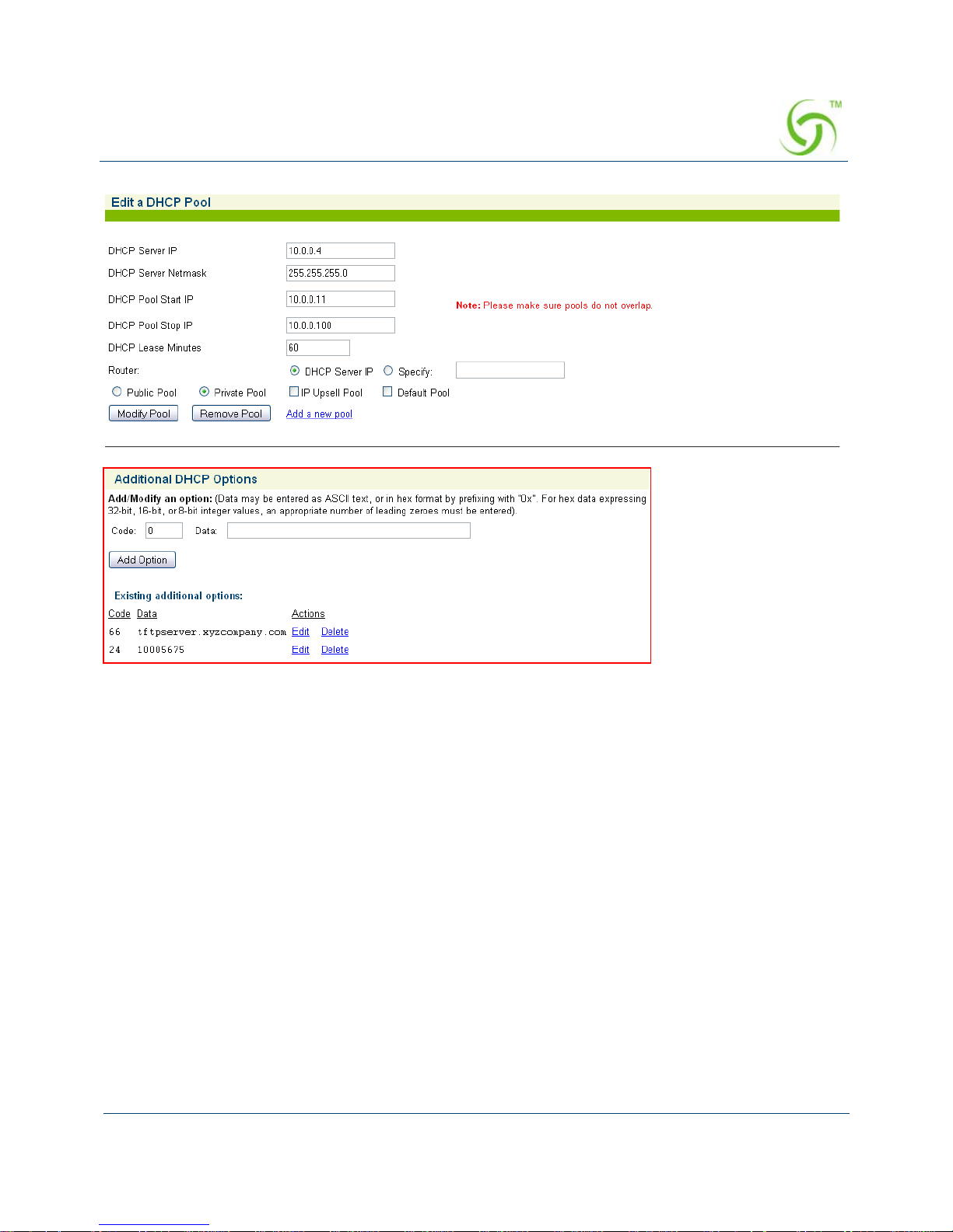
ACCESS GATEWAY
Installing the Access Gateway 49
Page 62
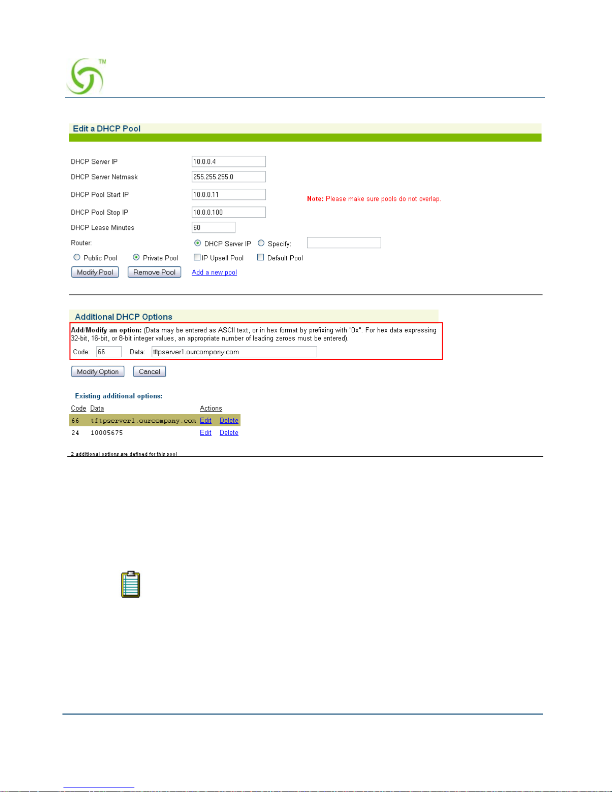
ACCESS GATEWAY
50 Installing the Access Gateway
Setting the DNS Options
DNS allows subscribers to enter meaningful URLs into their browsers (instead of complicated
numeric IP addresses) by automatically converting the URLs into the correct IP addresses. Y ou
can assign a primary, secondary, or tertiary (third) DNS server. The Access Gateway utilizes
whichever server is currently available.
Use the following procedure to set the DNS configuration optio ns.
1. Enter c (configuration) at the Access Gateway Menu. The Configuration menu appears.
2. Enter dn (dns) at the Configuration menu. The system displays the current domain (the
default is “nomadix”).
3. Enter a valid domain name (the Internet domain that DNS requests will utilize).
You must configure DNS if you want to enter meaningful URLs instead of numeric
IP addresses into any of the Access Gateway’s configuration screens.
Page 63

ACCESS GATEWAY
Installing the Access Gateway 51
4. Enter the host name (the DNS name of the Access Gateway). The host name must not
contain any spaces.
After assigning the host name, the system requests IP addresses for the primary,
secondary, and tertiary DNS servers (the default for the DNS primary address is 0.0.0.2).
5. Enter the IP addresses for the DNS servers (located at the customer’s network operating
center where DNS requests are sent).
6. You must now reboot the system for your settings to take effect. Enter y (yes) to reboot the
Access Gateway
Sample Screen Response:
Configuration>dns
NOTE: If DHCP Client or PPPoE Client is enabled, the Primary and
Secondary DNS Server may not be configured, since the DHCP/PPPoE server
may provide those items. Furthermore, if DHCP Client is configured, the
Domain may not be configured.
Enter domain [nomadix.com ]:
Enter host name (no spaces) [usg ]:
Enter primary DNS [0.0.0.2 ]: 4.2.2.2
Enter secondary DNS [0.0.0.0 ]:
Enter tertiary DNS [0.0.0.0 ]:
Enter DNS Redirection Port [1029 ]:
Enter Proxy DNS Port [1028 ]:
The system must be rebooted to function properly.
The DNS options have been established. DNS will now convert subscriber browser URLs
into the correct IP addresses automatically.
Archiving Your Configuration Settings
Once you have installed your Access Gateway and established the configuration settings, you
should write the settings to an archive file. If you ever experience problems with the system,
your archived settings can be restored at any time.
Refer to the following procedures:
“Exporting Configuration Settings to the Archive File {Export}” on page 223.
“Importing Configuration Settings from the Archive File {Import}” on page 228.
The secondary and tertiary DNS servers are only utilized if the primary DNS
server is unavailable.
Page 64

ACCESS GATEWAY
52 Installing the Access Gateway
Installing the Nomadix Private MIB
The Nomadix Private MIB is supplied on the “Accessories” CD-ROM, delivered with your
Access Gateway. After importing the nomadix.mib file from the CD-ROM you will be able to
view and manage SNMP objects on your Access Gateway.
Procedure
1. Import the nomadix.mib file into your SNMP client manager.
2. Connect to the Access Gateway from a node on the network that is accessible via the
Access Gateway’s network port (Internet, LAN, etc.). Be sure to enable the SNMP
daemon on the Access Gateway (available on the Access Gateway’s CLI or Web
Management Interface, under the Configuration menu –
snmp).
3. All variables defined by Nomadix start with the following prefix:
iso.org.dod.internet.private.enterprises.nomadix
4. You should now be able to define queries and set the SNMP values on your Access
Gateway. If necessary, consult this User Guide or your SNMP client manager’s
documentation for further details.
We recommend that you change the predefined community strings in order to
maintain a secure environment for your Access Gateway.
Page 65

ACCESS GATEWAY
2
System Administration 53
System Administration
This chapter provides all the instructions and procedures necessary for system administrators to
manage the Access Gateway on the customer’s network (after a successful installation).
The system administration procedures in this section are organized as they are listed under their
respective Web Management Interface (WMI) menus:
“Configuration Menu” on page 56
“Network Info Menu” on page 153
“Port-Location Menu” on page 1 61
“Subscriber Administration Menu” on page 173
“Subscriber Interface Menu” on page 187
“System Menu” on page 220
Choosing a Remote Connection
Once installed and configured for the customer’s network, the Access Gateway can be
managed and administered remotely with any of the following interface options:
Using the Web Management Interface (WMI) - Provides a powerful and flexible Web
interface for network administrators.
Using an SNMP Manager - Allows remote “Windows” management using an SNMP
client manager (for example, HP OpenView). However, before you can use SNMP to
access the Access Gateway, you must set up the appropriate SNMP communities. For
more information, refer to “Managing the SNMP Communities {SNMP}” on
page 140.
Using a Telnet Client
Choose an interface connection, based on your preference.
Now that the Access Gateway has been installed and configured successfully, this
User Guide moves away from the Command Line Interface (CLI) and documents
the Access Gateway from the Web Management Interface (WMI) viewpoint.
To use any of the remote connections (Web, SNMP, or Telnet), the network
interface IP address for the Access Gateway must be established (you did this
during the installation process).
Page 66

ACCESS GATEWAY
54 System Administration
Using the Web Management Interface (WMI)
The Web Management Interface (WMI) is a “graphical” version of the Command Line
Interface, comprised of HTML files. The HTML files are embedded in the Access Gateway
and are dynamically linked to the system’s functional command sets. You can access the WMI
from any Web browser.
To connect to the Web Management Interface, do the following:
1. Establish a connection to the Internet.
2. Open your Web browser.
3. Enter the network interface IP address of the Access Gateway (set up during the
installation process).
4. Log in as usual (supplying your user name and password).
T o access any menu item from the WMI, simply click on the item you want. The corresponding
work screen then appears in the right side frame. From here you can control the features and
settings related to your selection. Although the appearance is very different from the Command
Line Interface, the information displayed to you is basically the same. The only difference
between the two interfaces is in the method used for making selections and applying your
changes (selections are checkable boxes, and applying your changes is achieved by pressing
the
Submit button). Pressing the Reset button resets the screen to its previous state (clearing
all your changes without applying them).
Using an SNMP Manager
Once the SNMP communities are established, you can connect to the Access Gateway via the
Internet using an SNMP client manager (for example, HP OpenView). SNMP is the standard
protocol used in the Network Management (NM) system. This system contains two primary
elements:
Manager – The console (client) through which system administrators perform
network management functions.
Agent – An SNMP-compliant device which stores data about itself in a Management
Information Base (MIB). The Access Gateway is an example of such a device.
The Access Gateway contains managed objects that directly relate to its current operational
state. These objects include hardware configuration parameters and performance statistics.
Yo ur browser preferences or Internet options should be set to compare loaded
pages with cached pages.
Page 67
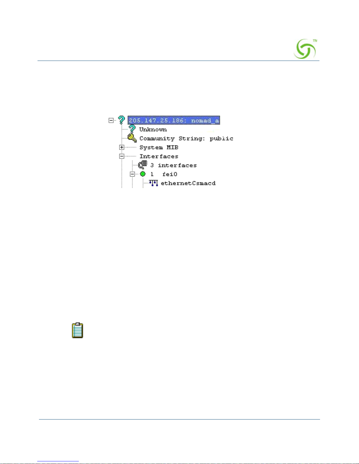
ACCESS GATEWAY
System Administration 55
Managed objects are arranged into a virtual information database, called a Management
Information Base (MIB). SNMP enables managers and agents to communicate with each other
for the purpose of accessing these MIBs and retrieving data. See also, “Installing the Nomadix
Private MIB” on page 52.
The following example shows a (partial) SNMP screen response.
Using a Telnet Client
There are many Telnet clients that you can use to connect with the Access Gateway. Using
T elnet provides a simple terminal emulation that allows you to see and interact with the Access
Gateway’ s Command Line Interface (as if you were connected via the serial interface). As with
any remote connection, the network interface IP address for the Access Gateway must be
established (you did this during the installation process).
Logging In
To access the Access Gateway’s Web Management Interface, use the Manager or Operator
login user name and password you defined during the installation process (refer to Assigning
Login User Names and Passwords).
About Your Product License
Some features included in this section will not be available to you unless you have purchased
the appropriate product license from Nomadix. In this case, the following statement will
User names and passwords are case-sensitive.
Page 68

ACCESS GATEWAY
56 System Administration
appear either immediately below the section heading or when the feature is mentioned in the
body text:
Configuration Menu
Defining the AAA Services {AAA}
This procedure shows you how to set up the AAA (Authentication, Authorization, and
Accounting) service options. AAA Services are used by the Access Gateway to authenticate,
authorize, and subsequently bill subscribers for their use of the customer’s network. The
Access Gateway currently supports several AAA models which are discussed in “Subscriber
Management” on page 248.
1. From the Web Management Interface, click on Configuration, then AAA. The
Authentication, Authorization, and Accounting Settings screen appears:
Your product license may not support this feature. You can upgrade your product
license at any time.
Page 69
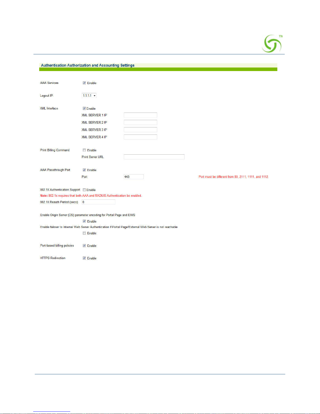
ACCESS GATEWAY
System Administration 57
Page 70
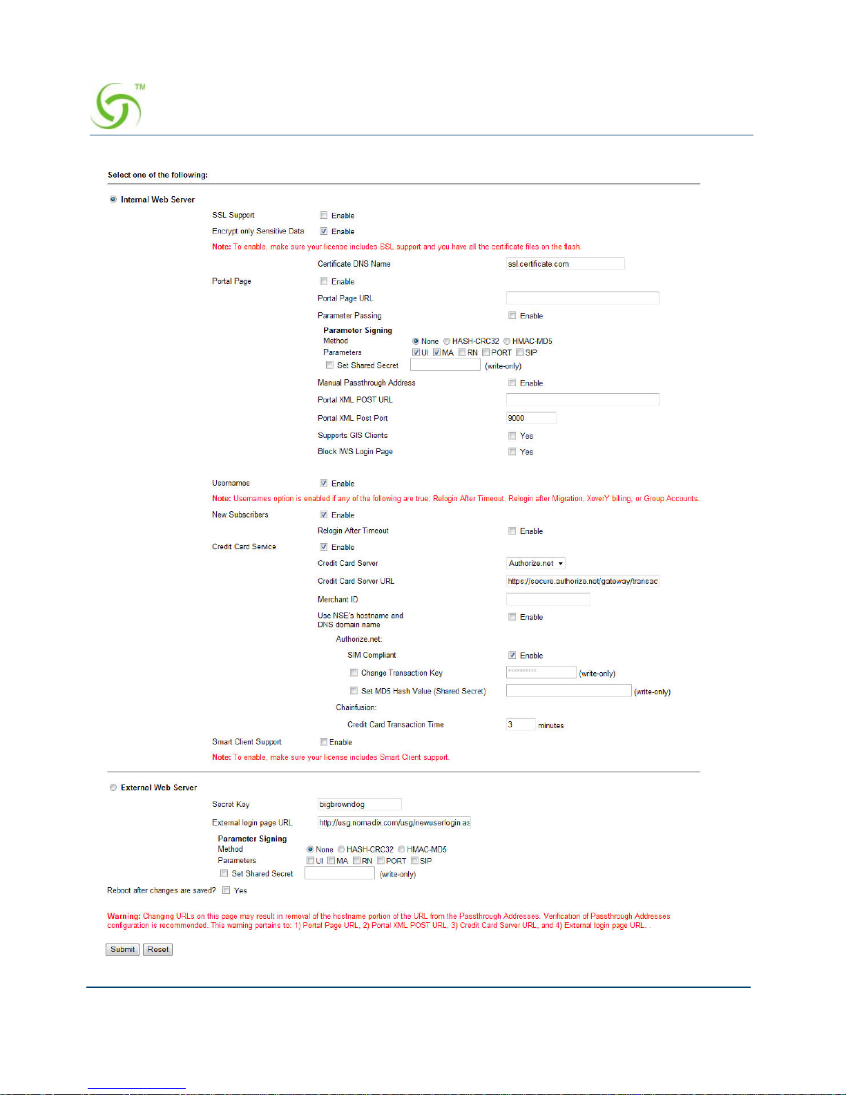
ACCESS GATEWAY
58 System Administration
Page 71

ACCESS GATEWAY
System Administration 59
2. Enable or disable AAA Services. If you enable AAA Services, go to Step 3, otherwise this
feature is disabled and you can exit the procedure.
3. Select a Logout IP address from the drop-down list. The list contains IP address that can
be used as the logout IP address. The default IP address is 1.1.1.1.
4. Enable or disable the XML Interface, as required.
XML (eXtensible Markup Language) is used by the Access Gateway’s subscriber
management module for port location and user administration. En abling the XML
interface allows the Access Gateway to accept and process XML commands from an
external source. XML commands are sent over the network to the Access Gateway. The
Access Gateway parses the query string, executes the commands specified by the string,
and returns data to the system that initiated the command request.
5. If you enabled the XML Interface feature, enter the XML IP (server) address.
6. Enable or disable Print Billing Command, as required. This feature enables NSE to
support Driverless Print servers. If this feature is enabled, you must enable the XML
interface and enter the IP address for the XML interface (Step 3 and Step 4). With Print
Billing enabled, print servers can bill subscribers’ rooms for printing their do cum e nts
without them having to install printers.
The DNS name print.server.com will internally resolve to the Configured Print Server
URL that is entered in the configuration. When subscribers are redirected to the Print
Server the NSE adds Parameters to that request, so that the Server is able to charge the
proper subscriber.
With these variables sent to the server it can now send the XML command to bill the users
properly.
Print Server IP needs to be entered as one of the XML server IP for the command to
successfully complete.
The XML command is:
<USG COMMAND="BILL_PRINT" IP_ADDR="">
<ROOM_NUM></ROOM_NUM>
<DOC_NAME></DOC_NAME>
<NUM_COPIES></NUM_COPIES>
<NUM_PAGES></NUM_PAGES>
<COST></COST>
<TIME_SUBMITTED></TIME_SUBMITTED>
</USG>
Subscribers could get to print.server.com by:
ICC button link
Printout in the hotel room
Page 72

ACCESS GATEWAY
60 System Administration
Link from the hotel’s HPR Page.
7. Enable or disable the AAA Passthrough Port feature, as required. System administrators
can set the Access Gateway to pass-through HTTPS traf fic, in addition to standard port 80
traffic, without being redirected. When access to a non-HTTPS address (for example, a
Search Engine or News site) has been requested, the subscriber is then redirected as usual.
8. If AAA passthrough is enabled, enter the corresponding port number.
9. Enable or disable the 802.1x Authentication Support feature, as required.
10. Enable or disable the Origin Server (OS) parameter encoding for Portal Page and EWS
feature, as required.
11. You can choose to Enable failover to Internal Web Server Authentication if Portal
Page/External Web Server is not reachable
by placing a check in that box.
12. Enable or disable Port Based Billing Policies.
The Port Location capabilities on the NSE have been enhanced. It is now possible to
define a policy on a port. The billing methods (RADIUS, Credit Card, PMS, L2TP
Tunneling) and the billing plans available on each port can now be individually
configured.
This ability allows for having different billing methods and billing plans on different ports
identified by VLANs or SNMP Port Query of the concentrator. A practical application of
this feature is to have a normal hotel room with a plan A that is $9.99 for a day with PMS
billing and have a meeting room with a plan of $14.99 an hour with Credit Card billing.
In order for the port-based po licies to work, you must enable Port Based Billing Policies.
See also “Adding and Updating Port-Location Assignments {Add}” on page 162.
13. Enable or disable HTTPS Redirection.
The NSE responds to regular HTTP requests from pending subscribers with a redirection
to the login screen. The NSE does not respond to HTTPS requests from pending
subscribers (HTTP requests with a destination port = 443) with a redirect; this will result
in a timeout or invalid certificate warning.
Your product license may not support this feature.
The port number must be different than 80, 2111, 1111, or 1112.
Both AAA and RADIUS Authentication must be enabled for 802.1x
Authentication support.
Page 73

ACCESS GATEWAY
System Administration 61
Enabling HTTPS Redirection adds a security exception to the user’ s browser to allow the
certificate received from the NSE to be always “valid.”
14. Depending on which authorization mode you choose, go to the following sub-sections in
this procedure:
Enabling AAA Services with the Internal Web Server – The IWS is “flashed” into the
system’s memory and the subscriber’s login page is served directly from the Access
Gateway.
Enabling AAA Services with an External W eb Server – In the EWS mode, the Access
Gateway redirects the subscriber’s login request to an external server (transparent to
the subscriber). The login page served by the EWS reflects the “look and feel” of the
solution provider ’s network and presents more login options.
Enabling AAA Services with the Internal Web Server
You are here because you want to enable the AAA Services with the Access Gateway’ s Internal
Web Server. The Access Gateway maintains an internal database of authorized subscribers,
based on their MAC (hardware address) and user name (if enabled). By referring to its
database record, also known as an authorization table, the Access Gateway instantly
recognizes new subscribers on the network.
You can configure the Access Gateway to handle new subscribers in various ways (see the
table on this page). With the IWS, you also have the option of enabling SSL support.
After selecting the Internal W eb Server authorization mode, you have the option of enabling or
disabling the Usernames and New Subscribers features. These features work in conjunction
with each other to determine how new subscribers are handled. Refer to the following table:
1. Select the Internal Web Server.
Usernames New Subscribers System Response
Disabled Enabled Allows new subscribers to enter the system without
giving a user name and password.
Enabled
(optional)
Enabled Allows new subscribers or authentication by their
user name and password.
Enabled Disabled New subscribers are not allowed. Only existing
subscribers are allowed after authenticating their
user name and password.
Disabled Disabled Y ou will not use this combination unless you want to
lock out all subscribers.
Page 74

ACCESS GATEWAY
62 System Administration
2. Enable or disable the SSL Support feature, as required. If you enable SSL Support, you
must provide a valid
Certificate DNS Name.
For more information about setting up SSL, go to Setting Up the SSL Feature.
SSL support allows for the creation of an end-to-end encrypted link between the Access
Gateway and its clients by enabling the Internal Web Server (IWS) to display pages under
a secure link—important when transmitting AAA information in a netw ork .
Adding SSL support to the Access Gateway requires service providers to obtain digital
certificates from VeriSign™ to create HTTPS pages. Instructions for obtaining certificates
are provided by Nomadix.
3. If you want to designate a portal page, you must enable the Portal Page feature, otherwise
leave this feature disabled.
4. If you enabled the Portal Page feature, provide the following supporting information:
Portal Page URL
Parameter Passing (enabled or disabled)
Parameter Signing (including Method, Parameters, and Shared Secret)
Portal XML POST URL
Portal XML Post Port
To enable SSL Support, your Access Gateway’s flash must include the server.pem,
cakey.pem, and cacert.pem certificate files (the “cacert.pem” file is provided
with your Access Gateway). For assistance, contact Appendix A: Technical
Support.
You must reboot the Access Gateway every time you enable or disable SSL
Support.
The Portal Page IP or DNS address are added to the IP passthrough list
automatically.
See Redirection Parameter Signing for more information about parameter
signing.
Page 75

ACCESS GATEWAY
System Administration 63
Support GIS Clients (enabled or disabled)
Block IWS Login Page (enabled or disabled)
5. Enable or disable the Usernames feature, as required (refer to the table in “Enabling AAA
Services with the Internal Web Server” on page 61).
Some subscribers may want additional account flexibility and security for their services
(for example, if they use more than one computer and their MAC address changes, or if
they move between port-locations). In this case, a subscriber can define a unique user
name and password which they can use from any machine or location (without being recharged). Subscribers who choose this option are prompted for their user name and
password whenever they try to access the Internet. Solution providers can charge a fee for
this service.
6. Enable or disable the New Subscribers feature (refer to the table in “Enabling AAA
Services with the Internal Web Server” on page 61).
7. If you enabled New Subscribers, enable or disable the Relogin After Timeout option.
8. You can now enable or disable the Credit Card Service. When this feature is enabled,
subscribers are prompted for their credit card information (for billing purposes). The
Access Gateway is configured to use either Authorize.net or Chainfusion (selected from a
pull-down menu). You will need to open a merchant account with Authorize.net,
Chainfusion or Datacenter (Luxembourg) before this feature can be used.
Please contact Nomadix Technical Support for assistance. Refer to “Contact Information”
on page 311.
GIS stands for Generic Interface Specification, a document written by iPass.
Enabling the Smart Client option in the Access Gateway automatically supports
all GIS compliant clients using the Internal Web Server. Enabling “Support for
GIS Clients” under the Portal Page feature means that the Access Gateway will
defer the managment of the GIS clients to the Portal Page server.
New Subscribers must be enabled before enabling the Credit Card and PMS
options.
All data communications between the Access Gateway and the credit card server
are encrypted by the SSL (Secure Sockets Layer) protocol. The Access Gateway
never “sees” subscriber credit card numbers.
Page 76

ACCESS GATEWAY
64 System Administration
9. If you enabled the Credit Card Service, define which service you require (Authorize.net
or
Chainfusion) from the pull-down menu.
10. If the Credit Card Service is enabled, enter the information for the following fields:
Credit Card Server URL
Credit Card Server IP
Merchant ID (a valid ID issued by the credit card reconciliation service provider –
Authorize.net or Chainfusion).
11. Check the Use NSE’s Hostname and DNS domain name box if you want the Hostname
and domain name to be sent to the Credit Card server instead of the local NSE IP address.
12. Enable or disable the SIM Compliant feature, as required. With this feature enabled, you
can change the transaction key at your discretion. To change the transaction key, simply
enter the key in the
Change Transaction Key box, then re-enter the key in the Verify
Transaction Key
box.
13. Enable or disable Smart Client Support, as required.
14. You can assign a session idle timeout parameter for subscribers (see following note). To
assign an idle timeout, simply enter a numeric value (in seconds) in the Subscriber Idle
Timeout
box (the default is 1200).
15. If you enabled or disabled SSL Support on this screen, you must click the check box for
Reboot after changes are saved? (the Access Gateway must be rebooted every time the
SSL Support feature is enabled or disabled).
16. Click on the Submit button to save your changes, or click on the Reset button if you want
to reset all the values to their previous state.
Enabling AAA Services with an External Web Server
You are here because you want to enable the AAA Services with an External Web Server
(EWS). In the EWS mode, the Access Gateway redirects the subscriber’s login request to an
external server.
DNS must be configured if you want to enter meaningful URLs instead of numeric
IP addresses into any of the Access Gateway’s configuration screens (for
example, the Credit Card Server URL in the following step).
The SIM Compliant option refers to Authorize.net's Simple Integration Method.
Subscriber Idle Timeout does not apply to RADIUS and Post Pay PMS
subscribers.
Page 77

ACCESS GATEWAY
System Administration 65
1. Select the External Web Server.
After enabling the External Web Server you must enter a Secret Key. The Secret Key
ensures that the response the Access Gateway gets from the EWS is valid.
2. Enter the Secret Key (The Access Gateway and the external authorization server must use
the same secret key).
3. Enter a valid External login page URL.
4. Configure the Parameter Signing options.
5. Click on the Submit button to save your changes, or click on the Reset button if you want
to reset all the values to their previous state (making changes to the EWS settings does not
require a system reboot).
Redirection Parameter Signing
External Web Server (EWS) and Internal Web Server (IWS) Portal Page Parameters can be
digitally signed, preventing malicious subscribers from intercepti ng, forging and replaying
URL redirection strings used by the NSE and EWS or IWS Portal Page to validate subscriber
access. This capability eliminates a vulnerability that was previously exploited to gain
unauthorized Internet access at charge-for-use sites.
The signing feature can create a cryptographically strong signature that protects the sensitive
portions of a URL redirection string (i.e., NSE ID, MAC address of the subscriber, etc), while
letting the EWS/Portal Page verify that the URL string has not been tampered or forged by the
subscriber.
DNS must be configured if you want to enter meaningful URLs instead of numeric
IP addresses into any of the Access Gateway’s configuration screens (for
example, the External login page URL in the following step).
See Redirection Parameter Signing for more information about parameter
signing.
Page 78
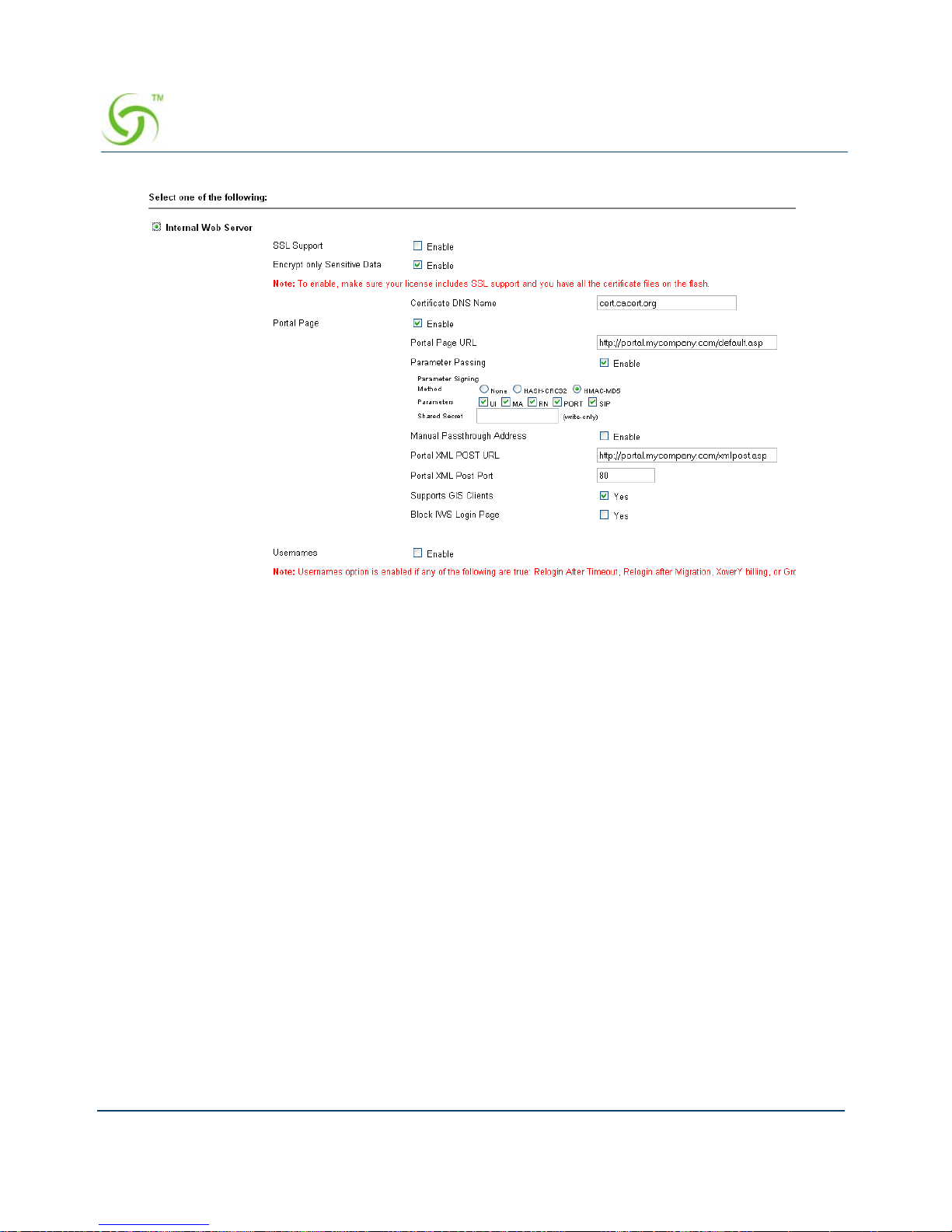
ACCESS GATEWAY
66 System Administration
The feature is configured by selecting a signing method, the parameters to be signed, and
assigning a secret key.
Two signature methods are supported:
HASH-CRC32
HMAC-MD5
Not all parameters that are part of the URL redirection string need to be included in the
signature calculation. The following parameters are considered sensitive and can be selected:
UI (the ID of the NSE)
MA (the subscriber’s MAC address)
RN (the Room Number)
PORT (the port number the subscriber is connected to)
SIP (the subscriber IP address)
The desired secret key simply needs to be entered in the field. Once entered, it is not visible to
the user.
Information that indicates which parameters were signed, along with the resultant hash value,
are then included in some additional parameters that are appended to the redirection string.
Page 79

ACCESS GATEWAY
System Administration 67
In order to utilize the parameter signing feature, the EWS or Portal Page Server used must be
configured to correctly parse and verify the signing information. Documentation that includes
guidelines for configuring a server to support signing can be obtained by contacting Nomadix
Technical Support.
Establishing Secure Administration {Access Control}
The Access Gateway allows you to block administrator access to interfaces (Telnet, WMI and
FTP, SSH and SFTP) and incorporates a master access control list that checks the source (IP
address) of administrator logins. A login is permitted only to the interfaces that have not been
blocked, and only if a match is made with the master “Source IP” list contained on the Access
Gateway. If a match is not made with the “Source IP list,” the login is denied, e ven if a correct
login name and password are supplied. The access control list for source IPs supports up to 50
(fifty) entries in the form of a specific IP address or range of IP addresses.
This procedure allows you to enable the “Access Control” feature and block administrator
access to specific interfaces, and add or remove administrator “Source IP” addresses.
The NSE supports secure https connections to the W eb Management Interface (WMI). Correct
certificates must be installed on the NSE flash memory for these connections to function
properly. The same certificate set that is used to support SSL connections for subscribers is
used for this purpose. For documentation about configuring the system to support secure
connections, contact technical support. See Appendix A: Technical Support.
In addition, corresponding options to block https connections (independent of http) are
included in the NSE's Access Control functionality, for both the network and subscriber sides.
If the required certificates are not resident on the flash, an attempted https connection will
generate an error syslog.
Page 80
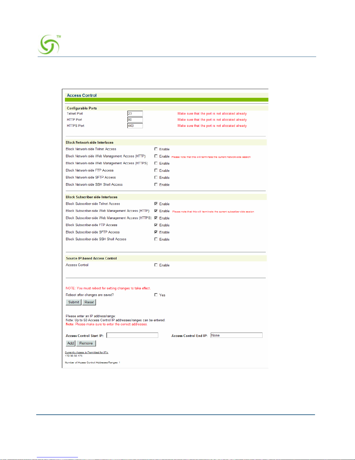
ACCESS GATEWAY
68 System Administration
1. From the Web Management Interface, click on Configuration, then Access Control. The
Access Control screen appears.
2. For Configurable Ports, enter a Telnet Port and an HTTP Port.
3. Enable or disable administrator access to any of the following interfaces:
Page 81

ACCESS GATEWAY
System Administration 69
Telnet Access
Web Management Access (HTTP)
Web Management Access (HTTPS)
FTP Access
SFTP Access
SSH Shell Access
4. Enable or disable subscriber-side interface blocking for any of the following interfaces
T elnet Access: enables/disables blocking of T elnet access from the subscriber -side to
the NSE Telnet interface. Default setting is enabled.
Web Management Access (HTTP): enables/disables blocking of Web Management
access from the subscriber-side to the NSE WMI. Default setting is enabled.
Web Management Access (HTTPS): enables/disables blocking of secure Web
Management access from the subscriber-side to the NSE WMI. Default setting is
enabled.
FTP Access: enables/disables blocking of FTP access from the subscriber-side to the
NSE. Default setting is enabled.
SFTP Access: enables/disables blocking of SFTP access from the subscriber-side to
the NSE. Default setting is enabled.
SSH Shell Access: enables/disables blocking of SSH shell access from the
subscriber-side to the NSE CLI. Default setting is disabled.
5. Click the check box for Access Control if you want to enable this feature, then click on
the Submit button to save your change.
If you enabled Access Control, administrator access is restricted only to the IP addresses
shown under the “Currently Access is Permitted for IPs” listing. If you want to add to or
remove IP addresses from the list, go to Step 6 through Step 8.
Blocking or unblocking interface access will terminate the current session.
Do not enable the blocking of all interfaces without setting up and enabling
SNMP. Enabling the blocking of all interfaces and disabling SNMP will
completely block access to the Access Gateway administration interface. For
assistance, contact Nomadix Technical Support.
The Access Control list can contain up to 50 (fifty) valid administrator IP
addresses or ranges of IP addresses.
Page 82

ACCESS GATEWAY
70 System Administration
6. T o add an IP address (or range of IP addresses) to the lis t, enter the “starting” IP address in
the
Access Control Start IP field.
7. If you are adding a range of IP addresses to the access control list, you must now enter the
“ending” IP address in the
Access Control End IP field. If you are adding a single IP
address, enter
None in the Access Control End IP field.
8. Click on the Add button to add the IP address (or range of IP addresses) to the list.
9. To remove an IP address (or range of IP addresses) from the list, enter the “start ing” IP
address in the
Access Control Start IP field.
If you are removing a range of IP addresses from the access control list, you must now
enter the “ending” IP address in the
Access Control End IP field. If you are removing a
single IP address, enter
None in the Access Control End IP field.
10. Click on the Remove button to remove the IP address (or range of IP addresses) from the
list.
Defining Automatic Configuration Settings {Auto Configuration}
The Access Gateway allows you to define parameters to enable the automatic configuration of
the system. See also, RADIUS-driven Auto Configuration.
If you enabled Access Control and have “locked yourself out,” of the system
(for example, because you’ve forgotten your password), you must establish a
local serial connection with the CLI to disable the Access Control feature, or
change the range of allowed IP addresses to access the management interfaces.
If you have changed the serial port to act as a PMS interface, please contact
Nomadix technical support. In this case, refer to “Contact Information” on
page 311.
Page 83
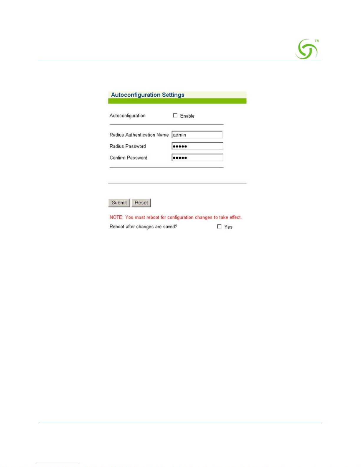
ACCESS GATEWAY
System Administration 71
1. From the Web Management Interface, click on Configuration, then Auto Configuration.
The Autoconfiguration Settings screen appears:
2. Enable or disable Autoconfiguration, as required.
3. If you enabled Autoconfiguration, you must enter the following information into the
corresponding fields:
RADIUS Authentication Name
RADIUS Password
Confirm Password
4. Click on the check box for Reboot after changes are saved? to reboot the system when
you submit your changes.
5. Click on the Submit button to save your changes, or click or the Reset button to reset all
data to its previous state.
See Enabling Auto Configuration.
Enabling Auto Configuration
As shown in the diagram below, two subsequent events drive the automatic configuration of
Nomadix devices:
1. A flow of RADIUS Authentication Request and Reply messages between the Nomadix
gateway and the centralized RADIUS server that specifies the location of the meta
Page 84
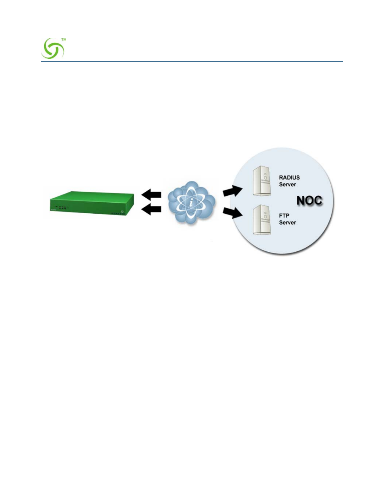
ACCESS GATEWAY
72 System Administration
configuration file (containing a listing of the individual configuration files and their
download frequency status) are downloaded from an FTP server into the flash of the
Nomadix device.
2. Defines the automated login into the centralized FTP server and the actual download
process into the flash.
The Auto-Configuration setup requires a few basic steps to be completed by both the field
engineer and the NOC administrator.
Administrative Steps to Enable Auto-Config
Typically, these tasks are performed either at a device pre-staging center or by the field
engineer.
1. Establish a WAN connection and electronically accept the EULA.
2. Setup RADIUS Server parameters (go to “Defining the Realm-Based Routing Settings
{Realm-Based Routing}” on page 130).
3. Setup Username and Password for RADIUS Authentication.
Administrative Steps to Enable Auto-Config for the NOC Administrator:
1. Add NAS IP address.
2. Add Nomadix Auto-Config VSA to the Nomadix dictionary file on the RADIUS server.
3. Create a RADIUS profile with the configuration VSA.
4. Create an FTP server with the configuration files.
Step 1: RADIUS Authen Req/Response
message to determine location of meta
configuration file
Step 2: FTP download of configuration files
(secure)
Page 85
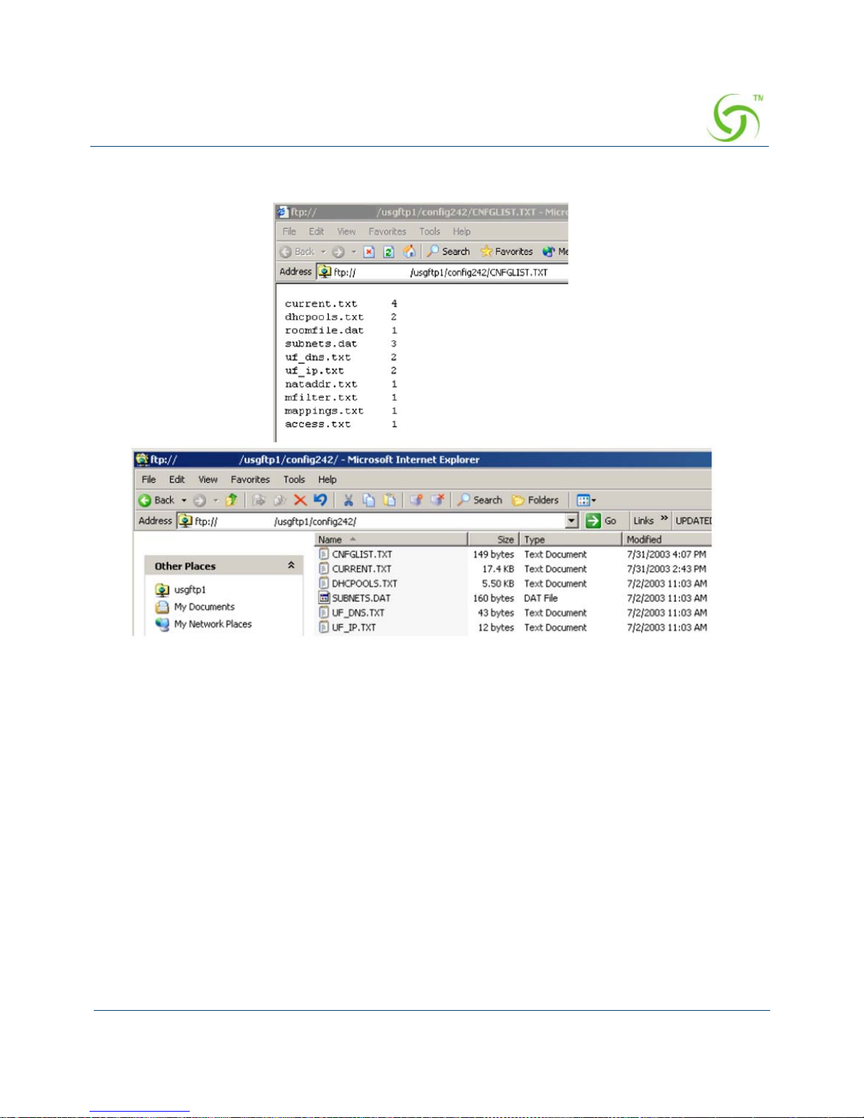
ACCESS GATEWAY
System Administration 73
5. The following diagram shows a sample RADIUS configuration file, meta file and
illustration of the FTP server setup.
The Nomadix device will automatically initiate one reboot to enable the new settings.
Configuration updates for network maintenance can be accomplished by simply enabling the
Auto-Configuration option and rebooting the device (for example, using SNMP). See also,
Defining Automatic Configuration Settings {Auto Configuration}.
Setting Up Bandwidth Management {Bandwidth Management}
The Access Gateway allows system administrators to manage the bandwidth for subscribers,
defined in Kbps (Kilobits per seconds) for both upstream and downstream data transmissions.
With the ICC feature enabled, subscribers can increase or decrease their own bandwidth
dynamically, and also adjust the pricing plan for th eir service.
Page 86
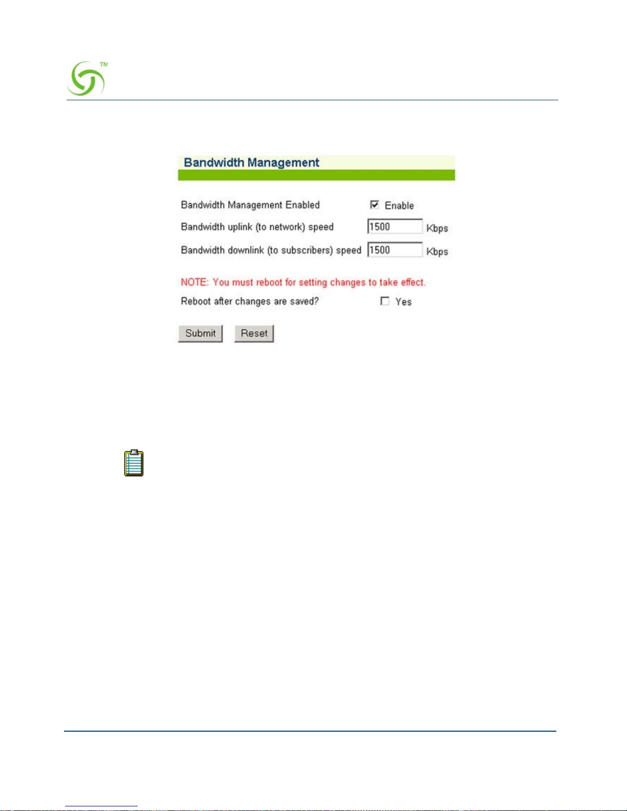
ACCESS GATEWAY
74 System Administration
1. From the Web Management Interface, click on Configuration, then Bandwidth
Management. The Bandwidth Management screen appears:
2. If required, click the check box for Bandwidth Mana geme nt Ena bl ed (this field is not
available on the AG2300 platform because Bandwidth Management is always enabled).
3. If you enabled Bandwidth Management, enter the uplink and downlink speeds (in Kbps) in
the appropriate fields.
4. If you made any changes to the settings on this screen, you must click the check box for
Reboot after changes are saved? (the Access Gateway must be rebooted).
5. Click on the Submit button to save your changes and reboot the system, or click on the
Reset button if you want to reset all the values to their previous state.
Group Bandwidth Limit Policy
The Group Bandwidth Limit Policy allows the you to assign a common bandwidth rate limiting
policy to a group of subscriber devices. All devices within the group share the total bandwidth
allocated to the policy.
The Group Bandwidth Limit Policy feature defines the following vendor-specific attributes
(VSAs):
Setting the uplink or downlink speeds to anything greater than what your product
supports is prevented by the NSE. Please refer to “Product Specifications” on
page 266 for your product’s capabilities.
Page 87

ACCESS GATEWAY
System Administration 75
Group Bandwidth Limit Policy – Operation
The NSE maintains a collection of all installed group bandwidth policies. The collection is
indexed by the bandwidth policy ID provided by the RADIUS server. The collection can store
as many policy records as the number of licensed subscriber devices. All subscriber devices
sharing the same group bandwidth policy ID belong to the same group. A subscriber device
can participate in only one bandwidth-limiting group at a time.
When a login is performed to an account that returns a bandwidth policy ID th at does not yet
exist in the NSE, a new policy record is created and inserted into the aforementioned
collection. The subscriber authorized by the Access-Accept is associated with the newly
installed bandwidth policy ID, and the bandwidth limits returned are invoked.
When the Access-Accept for a subscriber contains a bandwidth policy ID already present on
NSE, the subscriber is associated with the existing group po licy. All subscribers that are now
members of the group share the total bandwidth allocated to the policy.
If at some point a login is performed to an account that returns the policy ID for an existing
policy, but also returns bandwidth values different than those currently allocated for that
policy, the policy will be updated with the new values found in the Access-Accept. Thus, the
latest Access-Accept determines the current rates for the entire group.
The lifetime of a group policy record in the collection is determined by the session time of the
authorized (i.e. VALID) subscribers participating in the group. Group policy records are
removed from the collection when the last subscriber device belonging to the group is logged
out of the NSE regardless of the reason (e.g. session timeout, idle timeout, deletion of the
subscriber by an administrator, etc).
The NSE does not support the ability to enforce both per-subscriber and group bandwidth rates
simultaneously for the same subscribers. The RADIUS server must specify either per-
Nomadix
VSA #
Name Role/Value
19 GROUP_BW_POLICY_ID Defines the ID the for the group policy. Integer
between 1 and 16777215, inclusive.
20 GROUP_BW_MAX_UP Defines the total upstream bandwidth allowed
for the group in Kilobits per second. Integer
value. 0 is interpreted as unlimited.
21 GROUP_BW_MAX_DOWN Defines the total downstream bandwidth
allowed for the group in Kilobits per second.
Integer value. 0 is interpreted as unlimited.
Page 88
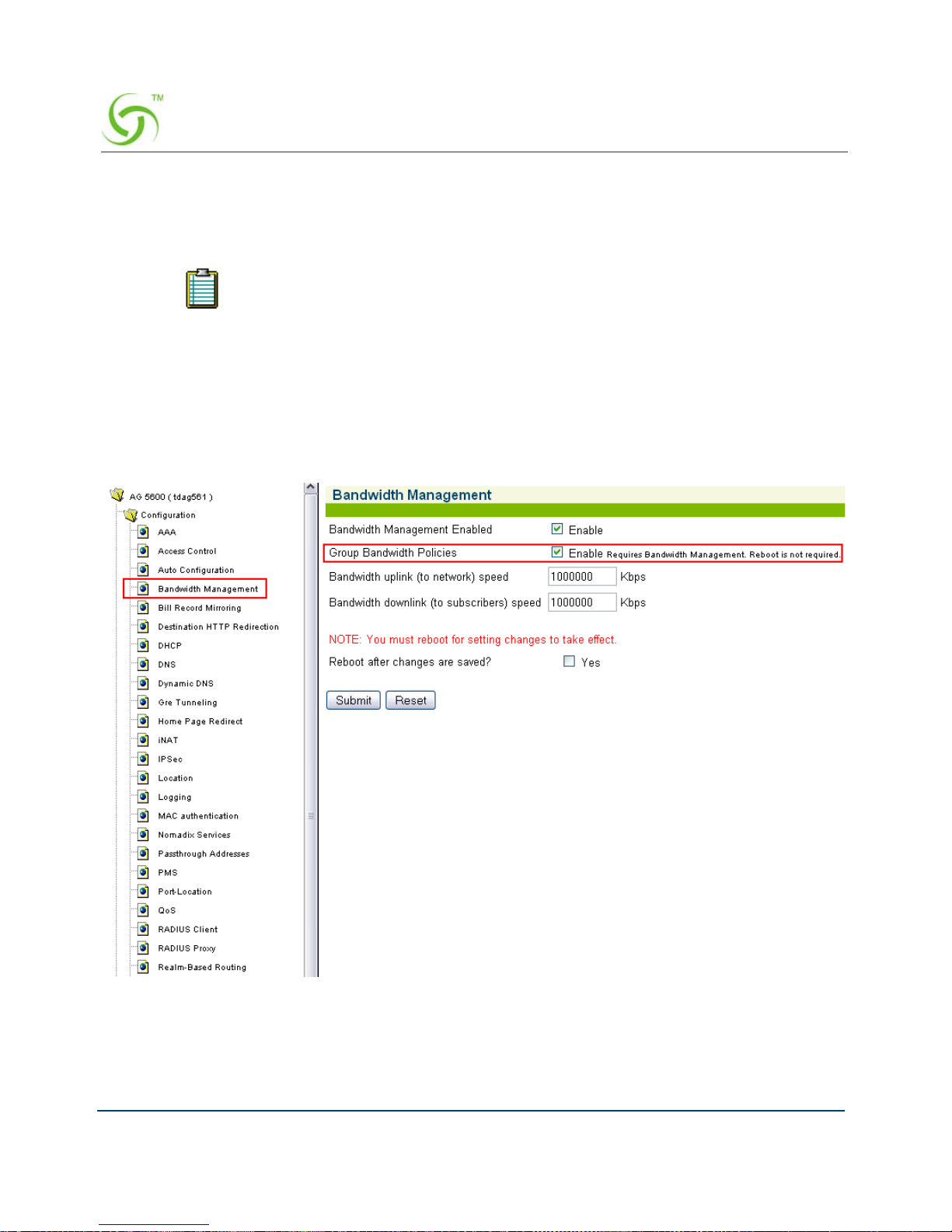
ACCESS GATEWAY
76 System Administration
subscriber or group bandwidth attributes. However, in case a RADIUS Access-Accept contains
both individual and group bandwidth attributes, the NSE will use the group attributes and
ignore the per-subscriber attributes.
Group Bandwidth Limit Policy – Enable
The Group Bandwidth feature is globally enabled via an option on the Bandwidth management
page.
The NSE can concurrently support some subscribers as part of a group and some
others with limits set on a per-subscriber basis. However, a single subscriber
cannot be assigned group membership and individual limits at the same time.
Page 89
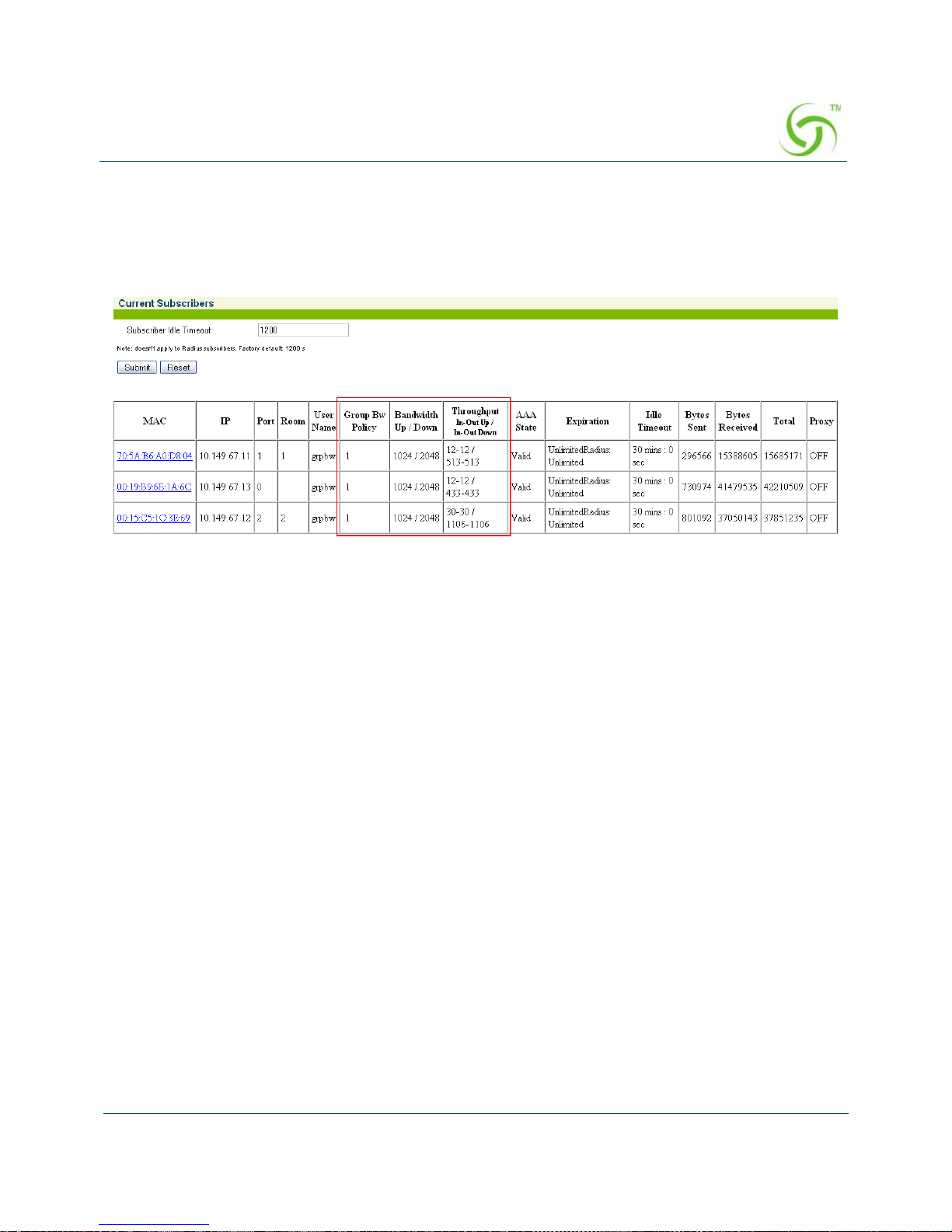
ACCESS GATEWAY
System Administration 77
Group Bandwidth Limit Policy – Current Table
When the feature is enabled, a group bandwidth policy ID column is displayed in the current
table. Once policies are instantiated, policy information can be viewed via XML.
Establishing Billing Records “Mirroring” {Bill Record Mirroring}
The Access Gateway can send copies of credit card transaction and PMS billing records to
external servers that have been previously defined by system administrators. The Access
Gateway assumes control of billing transmissions and saving billing records. By “mirroring”
the billing data, theAccess Gateway can also send copies of billing records to predefined
“carbon copy” servers. Additionally, if the primary and secondary servers are down, the
Access Gateway can store up to 2,000 credit card transaction records. When a connection is reestablished (with either server), the Access Gateway sends the stored information to the
server—no records are lost!
For more information about the bill record mirroring feature, go to “Mirroring Billing
Records” on page 300.
1. From the Web Management Interface, click on Configuration, then Bill Record
Mirroring. The Credit Card/PMS Mirroring Settings screen appears:
Page 90
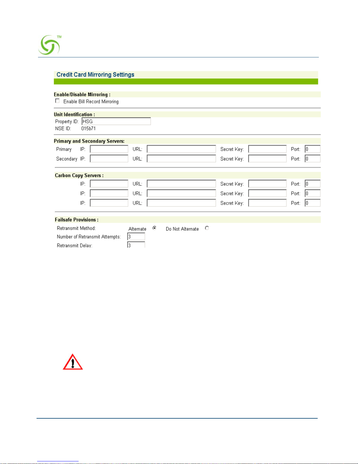
ACCESS GATEWAY
78 System Administration
2. If you want to enable the billing records “mirroring” functionality for credit card
transactions, click on the check box for
Enable Bill Record Mirroring.
3.
Enter the property identification code in the Property ID field.
4. Enter the communication parameters for the primary server that is to be used for mirroring,
including:
Primary IP
URL
Secret Key
5. Repeat Step 4 for the secondary server (if any) and all carbon copy servers.
6. Define the “fail-safe” provisions, including:
Retransmit Method – Alternate, or do not alternate.
The Access Gateway and the “mirror” servers must use the same secret key.
Page 91

ACCESS GATEWAY
System Administration 79
Number of Retransmit Attempts – This tells the system how many times it should
attempt to retransmit billing records before suspending the task.
Retransmit Delay – This specifies the time delay between each retransmission.
7. Click on the Submit button to save your changes, or click on the Reset button if you want
to reset all the values to their previous state.
Configuring Destination HTTP Redirect
Destination HTTP Redirect provides DNS-triggered redirection of HTTP requests to one or
more portal page URLs configured on the NSE. Portal pages could include account status,
maps, local information, etc.
The NSE will intercept and respond to DNS queries containing configurable strings.
Subscribers requesting a website at that DNS will obtain a DNS response that contains a
“magic” IP address (which is the same value obtained when the subscriber queries the DNS
string “logout.nomadix.com”).
The NSE will process HTTP requests for that “magic” IP address (configurable on the AAA
page), and will reply with an HTTP redirection (which may include a number of signed
redirection parameters) to a configured URL. By following the HTTP redirection, the
subscriber will reach the target URL, and he/she will then be served a page containing
whatever information is relevant (account and/or other specific information).
Page 92

ACCESS GATEWAY
80 System Administration
The figure above illustrates destination HTTP redirection, assuming a DNS query string for
www.example.com, a magic IP address of 1.1.1.1, and a portal page URL of
portal1.myhotel.com. Given this configuration, the following would apply:
A DNS query for www.example.com is intercepted by the NSE, which responds with
the magic IP address. Then, the subscriber’s browser sends an HTTP request to the
magic IP and sets the Host header to www.example.com.
The NSE will process the HTTP request and will analyze the Host header to find the
redirection URL that corresponds to www.example.com, which is
portal1.myhotel.com in this example. The NSE will then craft an HTTP redirection
response that contains the portal page URL, followed by a query string. The string
will include various redirection parameters, time-stamped and signed, if signing is
enabled for that entry (which it is not in this example).
The subscriber will follow the redirection string and will land on the portal page URL.
The portal will verify and analyze the query string and then will return the relevant
information (likely about the subscriber’s account status, depending on what the
portal is configured to handle).
User NSE ExternalServer
portal1.myhotel.com/
DNSquery:www.example.com?
*DNSresponse:1.1.1.1
GET/ HTTP/1. 1…
Host:www.example.com
***HTTP/1.1200 OK
…
**HTTP/1.0302 RD
Location:
portal1.myhotel.com/details?OS=..&UI=..&MA=..&RN=..&PORT=..&SIP=..&TS= ..&NO
NCE=..&SIGN=..&SIGNED=..&METHOD=..
…
* Magic I P Addr es s
** Redirect Message
*** OK Accept Me ssage
GET
details?OS=..&
UI=..&MA=..&RN=..&PORT=..&SIP=..&TS=..&NONCE=..&SIGN=..&
SIGNED=..&METHOD=..H TTP/1.1
Host:
portal1.myhotel.com
Page 93
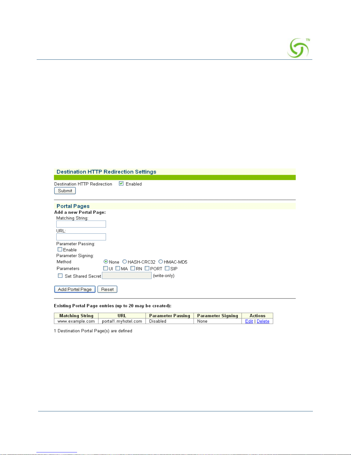
ACCESS GATEWAY
System Administration 81
After successful redirection occurs the list of signed parameters and signature
methods are passed to the portal page.
HTTP/1.0 302 RD
http://portal1.myhotel.com/details?OS=<Original
Server>&UI=<NSE’s ID>&MA=<subscriber’s MAC>&RN=<Room
name>&PORT=<VLAN>&SIP=<subscriber’s
IP>&TS=<timestamp>&NONCE=<16 chars>&SIGN=<signature>&
SIGNED=<list of signed parameters>& METHOD=<signature
method>
1. From the Web Management Interface, click on Configuration, then Destination HTTP
Redirection. The Destination HTTP Redirection Settings screen appears:
2. To enable Destination HTTP Redirection, click on the Enabled check box. The default
setting is disabled.
You may create up to 20 port al pages.
3. In the Portal Pages section, enter the matching string that will be directed to the portal
page in the
Matching String field.
4. Enter the portal page’s URL in the URL field.
Page 94

ACCESS GATEWAY
82 System Administration
5. To enable parameter passing, click on the Parameter Passin g Enable check box.
6. Select the Parameter Signing:
Method:
None, HASH-CRC32, or HMAC-MD5 (select one method).
Parameters:
UI, MA, RN, PORT, and SIP (select all applicable parameters).
7. T o enable Set Shared Secret, click on the Set Shared Secret check box. If you enable this
feature, enter the shared secret text string in the Set Shared Secret field.
8. Click on the Submit button to save the redirection settings, or click on the Reset button if
you want to reset all the values to their previous state.
Portal page setting are saved to the table in
Existing Portal Page entries section of the
screen. From that table, you can edit or delete existing portal pages
Managing the DHCP service options {DHCP}
When a device connects to the network, the DHCP server assigns it a “dynamic” IP addres s for
the duration of the session. Most users have DHCP capability on their computer. To enable this
service on the Access Gateway, you can either enable the DHCP relay (routed to an external
DHCP server IP address), or you can enable the Access Gateway to act as its own DHCP
server. In both cases, DHCP functionali ty is necessary if you want to automatically assign IP
addresses to subscribers.
Page 95
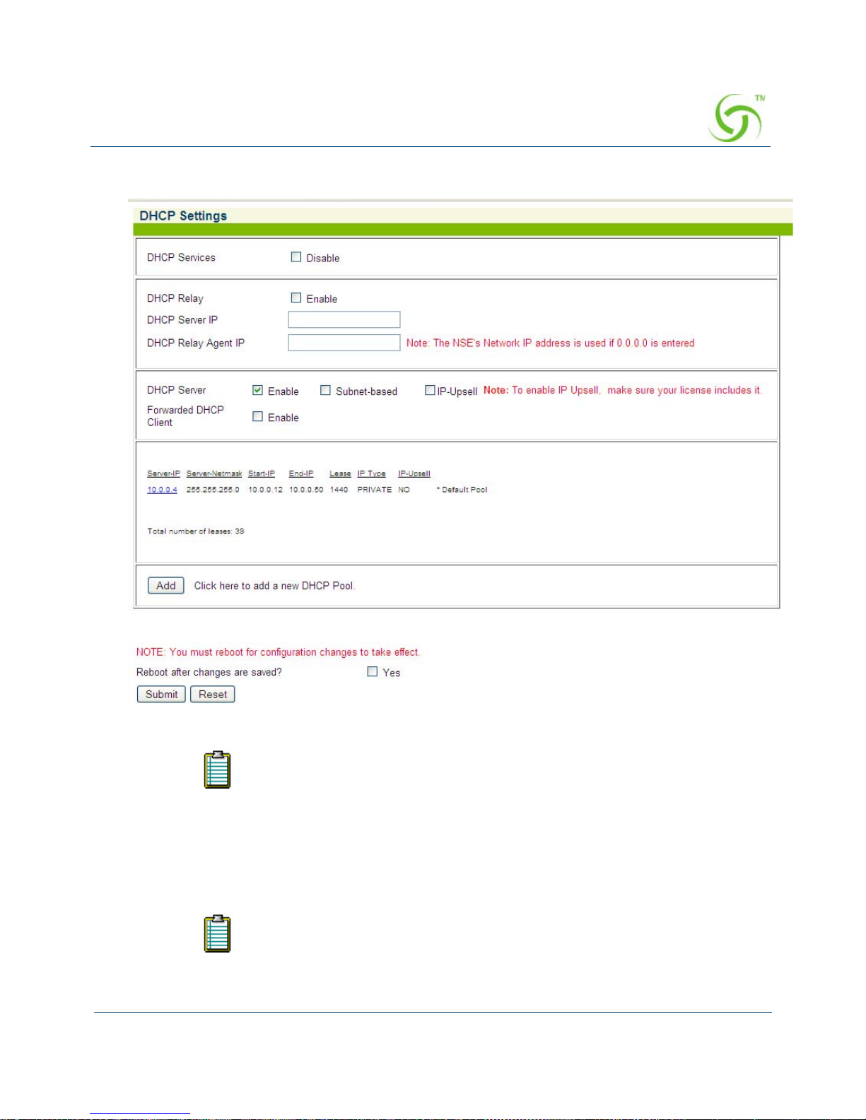
ACCESS GATEWAY
System Administration 83
1. From the Web Management Interface, click on Configuration, then DHCP. The
DHCP Settings screen appears:
2. DHCP Services is enabled by default. Do not disable it unless you want to lose
all your DHCP services.
Nomadix’ patented Dynamic Address Translation (DAT) functionality is
automatically configured to facilitate “plug-and-play” access to subscribers who
are misconfigured with static (permanent) IP addresses, or subscribers that do
not have DHCP capability on their computers. DAT allows all users to obtain
network access, regardless of their computer’s network settings.
By default, the Access Gateway is configured to act as its own DHCP server and
the relay feature is disabled. If you want the Access Gateway to act as its own
DHCP server, do not enable the relay. Go directly to Step 8.
Page 96

ACCESS GATEWAY
84 System Administration
3. To route DHCP through an external server, enable the DHCP Relay.
4. If you enabled the DHCP Relay feature, you must assign a valid DHCP Server IP address
(the default is 0.0.0.0) and a valid
DHCP Relay Agent IP address.
The DHCP Relay Agent allows the Access Gateway to request a specific range of IP
addresses from different IP pools from the DHCP Server. Leaving thes e fields blank forces
the system to use the IP pool that contains IP addresses that are on the same subnet as the
Access Gateway.
5. If you want the Access Gateway to act as its own DHCP Server (you did not enable the
DHCP Relay), enable it now.
6. If required, you can make the DHCP Server feature Subnet -based by checking the
appropriate box.
7. If required, enable the IP Upsell feature.
System administrators can set two different DHCP pools for the same physical LAN.
When DHCP subscribers select a service plan with a public pool address, the Access
Gateway associates their MAC address with their public IP address for the duration of the
service level agreement. The opposite is true if they select a plan with a private pool
address. This feature enables a competitive solution and is an instant revenue generator for
ISPs. The IP Upsell functionality solves a number of connectivity problems, especially
with regard to L2TP and certain video conferencing and online gaming applications.
Y ou must disable the DHCP server befor e enabling the DHCP relay. Both features
cannot be enabled concurrently.
If the DHCP Relay Agent IP address is set for an address that is already used or
the IP address of the server, the other system will get an IP conflict and will not
have Internet access.
Page 97
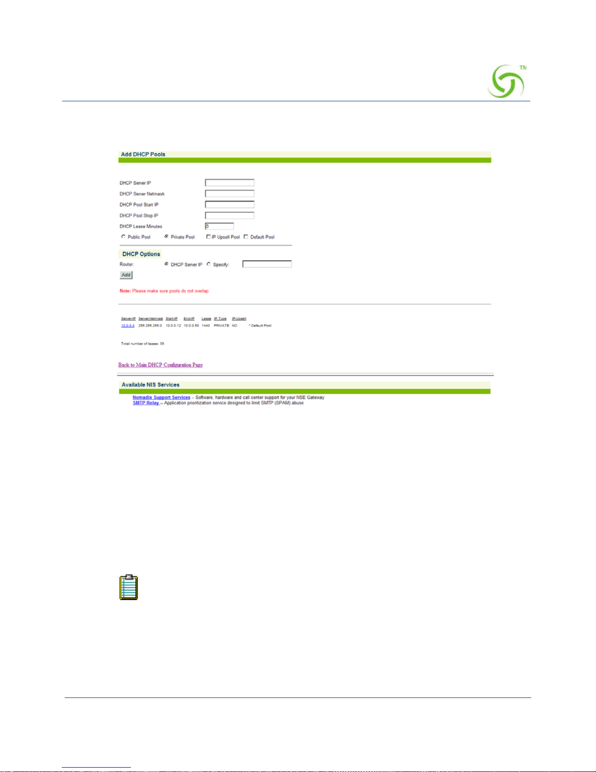
ACCESS GATEWAY
System Administration 85
8. If you want to add a new DHCP Pool, click on the Add button. The Add DHCP Pools
screen appears:
9. Enter a valid DHCP Server IP address for the DHCP server.
10. Enter the DHCP Server Netmask.
11. Enter the starting and ending IP addresses for the DHCP address pool you want to use:
DHCP Pool Start IP
DHCP Pool Stop IP
12. Enter the DHCP Lease Minutes.
13. Select Public Pool or Private Pool, as required.
A “public” IP address will not be translated by DAT.
Page 98

ACCESS GATEWAY
86 System Administration
14. If required, make this an IP Upsell Pool and/or the Default Pool by checking the
appropriate boxes.
15. Optional, if the gateway router for the DHCP Pool is other than that of the DHCP Server
IP, select
Specify and enter the IP address of the gateway router of choice.
16. When finished establishing your DHCP Pools, click on the Back to Main DHCP
Configuration Page
to return to the previous page.
17. Y ou must now reboot the system for the new settings to take effect. Click the check box for
Reboot after changes are saved? then click on the Submit button to save your changes
and reboot the system, or click on the
Reset button if you want to reset all the values to
their previous state.
The existing lease pool and lease table are deleted and the Access Gateway reboots. The
Access Gateway can issue IP addresses to any DHCP enabled subscriber who enters the
network.
Enabling DNSSEC Support
DNSSEC support adds authentication and integrity capability to DNS systems. The DNSSEC
feature in the NSE allows DNSSEC queries and responses to traverse the NSE between
subscribers and the NSE’s configured DNS servers. The NSE itself does not participate in
DNSSEC trust relationships with subscribers. Reboot is not required.
Use the following procedure to set the DNS configuration optio ns.
1. From the Web Management Interface, click on Configuration, then DNS. The Domain
Name System (DNS) Settings screen appears:
Do not allow pools to overlap.
Page 99
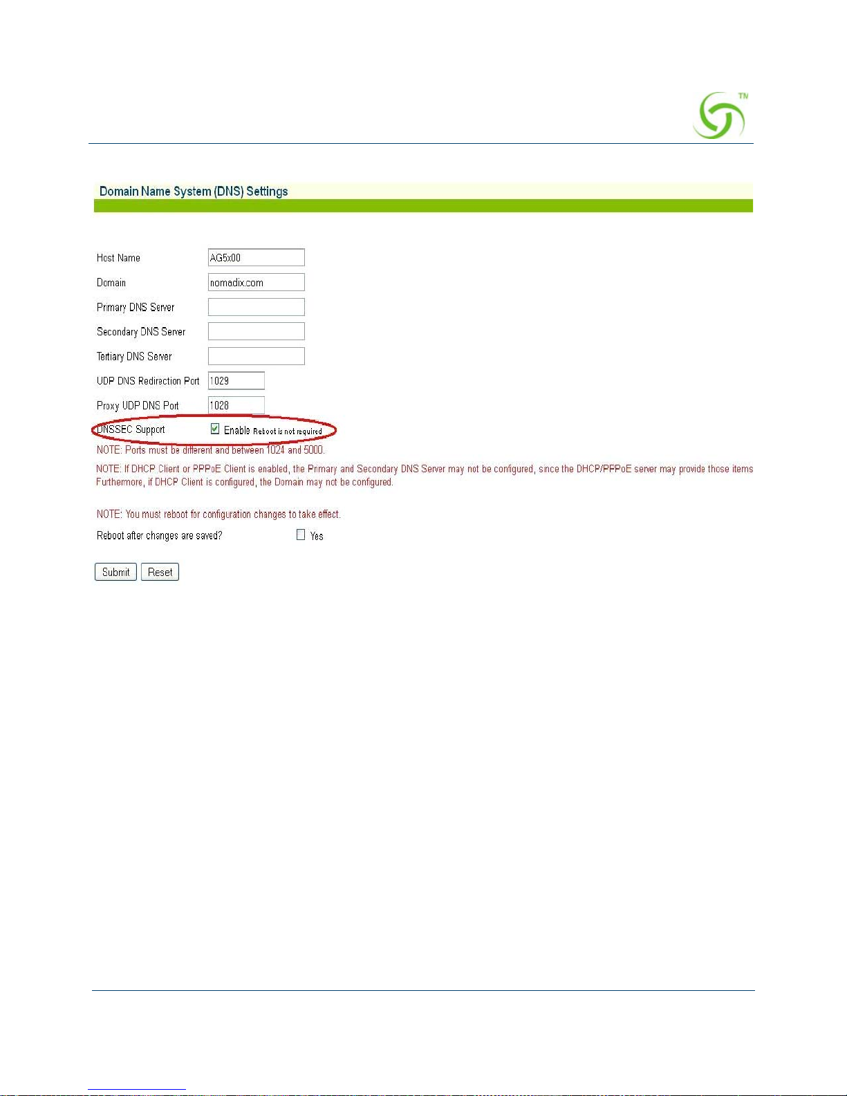
ACCESS GATEWAY
System Administration 87
2. Check the Enable check box to enable DNSSEC Support functionality. The default setting
is disabled.
3. Click on the Submit button to save your changes (reboot is not required), or click on the
Reset button if you want to reset all the values to their previous state.
Managing the DNS Options {DNS}
DNS allows subscribers to enter meaningful URLs into their browsers (instead of complicated
numeric IP addresses) by automatically converting the URLs into the correct IP addresses. Y ou
can assign a primary, secondary, or tertiary (third) DNS server. The Access Gateway utilizes
whichever server is currently available.
Use the following procedure to set the DNS configuration options.
1. From the Web Management Interface, click on Configuration, then DNS. The Domain
Name System (DNS) Settings screen appears:
Page 100

ACCESS GATEWAY
88 System Administration
2. Enter the Host Name (the DNS name of the Access Gateway).
3. Enter a valid Domain name (the Internet domain that DNS requests will utilize).
4. Enter the IP addresses for the DNS servers (located at the customer’s network operating
center where DNS requests are sent). Servers include:
Primary DNS Server
Secondary DNS Server
Tertiary DNS Sever
5. Enter a DNS Redirection Port and a Proxy DNS Port.
6. When finished, you must reboot the system for the new settings to take effect. Click on the
check box for Reboot after changes are saved? to reboot the system after saving your
changes.
7. Click on the Submit button to save your changes and reboot the system, or click on the
Reset button if you want to reset all the values to their previous state.
Managing the Dynamic DNS Options {Dynamic DNS}
Use the following procedure to set the Dynamic DNS options.
The host name must not contain any spaces.
The secondary and tertiary DNS servers are only utilized if the primary DNS
server is unavailable.
 Loading...