

Page 1

USERS GUIDE
Version 1.0.2
Published July 2005
Page 2
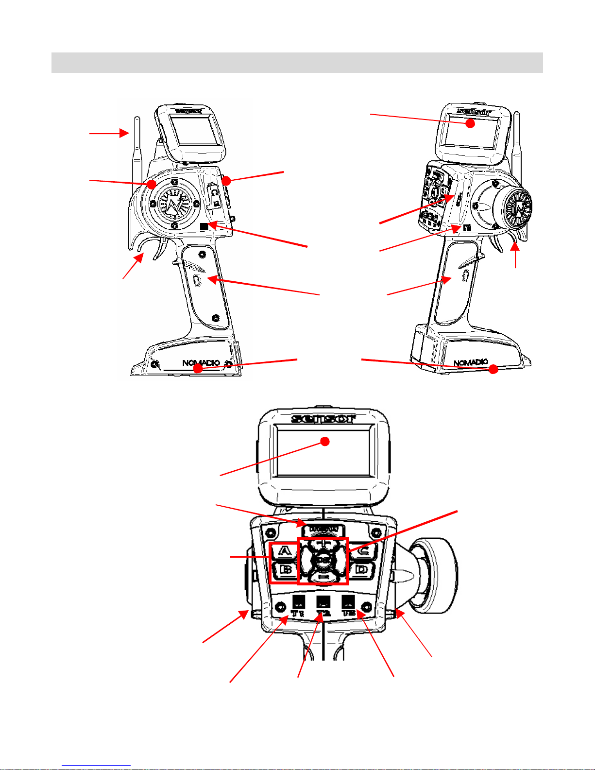
Sensor Quick Reference
Antenna
Speaker
Throttle
Trigger
Display Screen
Menu Button
Display Screen
Headphone &
PC Conne ctions
On/Off Sw itch
Ste eri ng Tr im
Steering W heel
S h ift Butto n s
Battery
Compartment /
Receiver Program ming
Cable
Navigation
Controls
Selecti on Buttons
(TL) Steering Tr im
(T1) Throttle Dual
Rate Trim
(T2) Steering Dual
Rate Trim
(TR) Stee r ing Trim
(T3) Throttle Tr im
Page 3
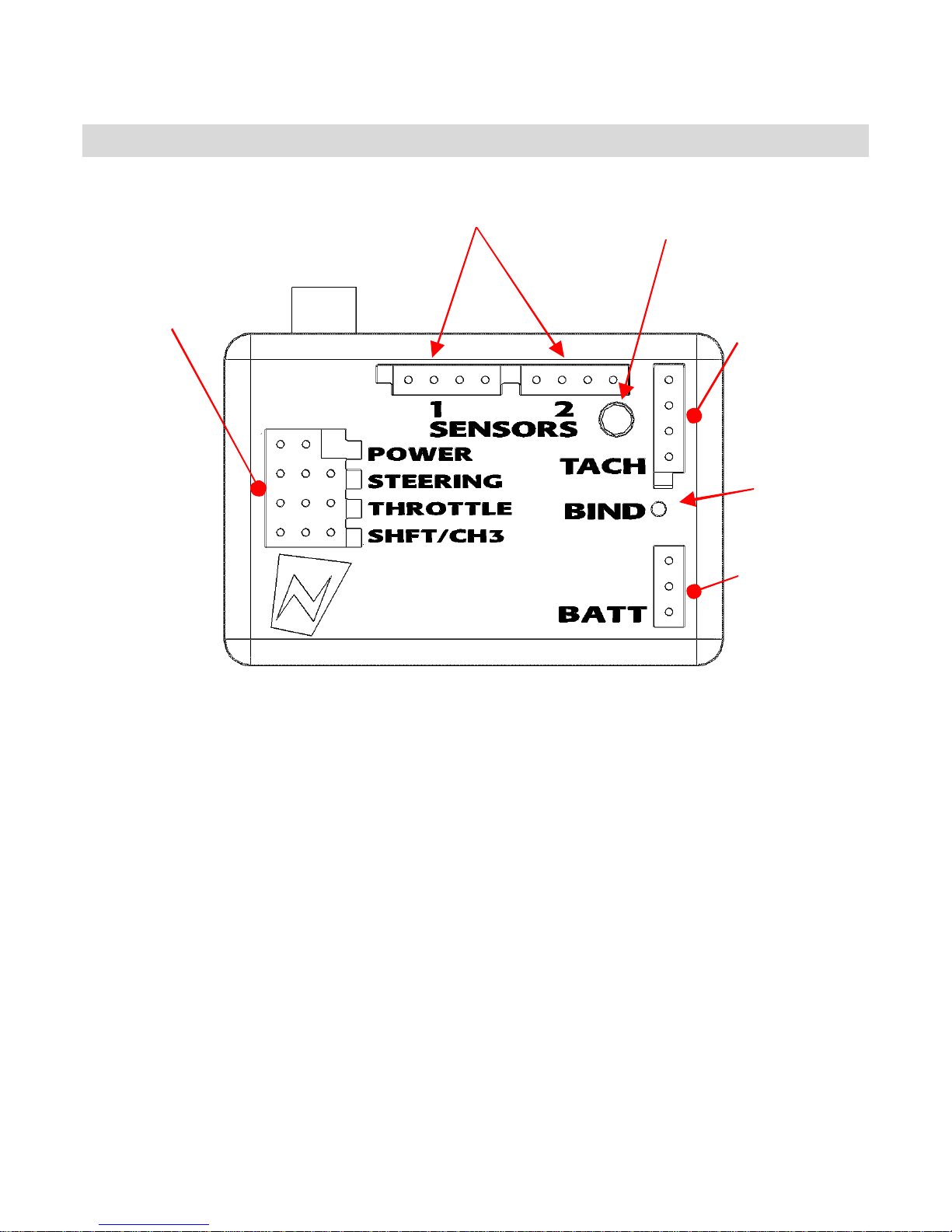
Transceiver Quick Reference
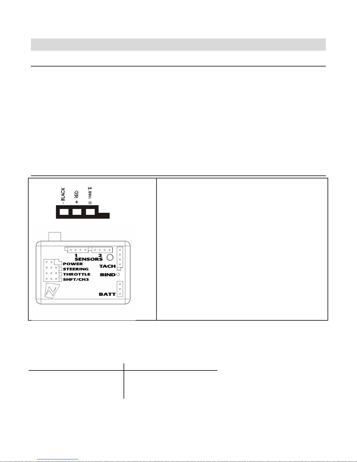
Receptacles for:
RX B attery (power )
Ste eri ng (Ch1 )
Throttl e (Ch2 )
S h ift S ervo (Ch3)
Receptacle for:
Analog Sensor s
(e.g., Temp)
Indicator LE D
Receptacle for:
Digital Sens or (e.g.,
RPM/Speed ) /Receiver
Progr am m i ng Cable
BIND bu tton
(recessed)
Receptacle for:
Ca r Battery Sen sor
Page 4

Sensor Quick Ref erence.................................. II
Transceiver Quick Re ference.........................III
Statement of C ompliance ................................ 2
Getting t o know your Sensor........................... 3
Po wer Switc h......................................................3
Display Screen....................................................3
Menu Butt on.......................................................3
Na vigat ion Button s ...............................................3
S election B uttons.................................................4
Trim Butto ns.......................................................4
Gri p Butt ons.......................................................4
Connec ti on Ports.................................................4
Charging and Installing Batte ries ...................5
Charg ing the Suppli ed Ni MH Batt eri es......................5
I nstalling the Bat teries.......................................... 5
Adjusting the Screen........................................ 6
Conve rting for Le ft H anded Use...................... 7
Installing the Transceiver................................9
M ounting the Transceiver......................................9
Connecting the Transceiver....................................9
Installing the Sensors....................................10
Receiver Battery Sensor......................................10
Voltag e Sens or..................................................10
Temper atu re Sensor...........................................10
Connec tin g the Temper atu re S enso r......................11
Binding the Transceiver.................................12
How the Bindi ng Proc ess Wor ks ............................12
Binding your transceiv er the first time....................14
Sensor Contr ol s ..............................................15
Top Menu Le vel .................................................16
Ste er in g Func ti ons............................................. 16
Throt tle Funct ion s ..............................................30
Shif t Ser vo Func tio ns.......................................... 46
Model Manage ment............................................ 56
Contr oll er Setup................................................ 60
Failsafes.......................................................... 64
Sensor Digi tal RC Desktop.............................66
Mini mu m Syst em Requ ir em ent s............................66
I nsta lling the RC De sktop.................................... 66
Connec tin g the Sens or to your Co mput er................ 73
Usin g the Senso r Digi tal R C Des ktop...................... 73
Registration......................................................74
Receiving Sett ing s From the Sensor....................... 76
Edit in g Setting s.................................................77
Sa ving Setti ngs................................................. 77
S ending Settings to the Sensor............................. 78
Installing Sensor Fir mware.................................. 78
Specifications .................................................79
Senso r Cont ro ller ...............................................79
Transceiver ...................................................... 79
Support ...........................................................80
Nomadio 3 Year Limited Warranty................81
War ran ty Cover age............................................81
E xclusions and Limitations...................................81
Page 5

Statement of Complia nce
FCC Co mp liance Statement
This equipment ha s been teste d and found to compl y wit h the limits for a Cl ass B digital device, pursuant to Part
15 of the FCC Rules. These limits are designed to provide reasonable protection against harmful interference in a
re sidentia l install ation. This equipme nt generat es, use s and can ra diate ra dio fre quency energy and, if not
i nstalled and use d in accorda nce with t he instruct ions, may cause harmful interference t o radio communicati ons.
However, there is no guarantee that interference will not occur in a particular installation.
If this equipment does cause harmful interference to radio or television reception, which can be determined by
turning the equipment off and on, the user is encouraged to try to correct the interference by one or more of the
following measures:
– Reorient or relocate the receiving antenna.
– Increase the separation between the equipment and recei ver.
– Connect the equipment into an outlet on a circuit different from that to which the receiver is connected.
– Consul t the dea ler or a n experienced te chnician for help.
• This device complies with Part 15 of the FCC Rules and with RSS-210 of Industry Canada.
Operation is subject to the following two conditions:
1) this device my not cause ha rmful i nterf erence, and
2) this device must accept any inte rfere nce rece ived, including interference that ma y cause undesi red operation.
• The users manual or instruction manual for an intentional or unintentional radiator shall caution the user that
changes or modifications not expressly approved by the party responsible for compliance could void the user's
authority to operate the equipment.
Warning: Changes or modi fications made to this equipment not e xpressly approved b y Nomadi o may void the
FCC authorization to operate this equipment.
RF Exp o su re St at ement
This transmitter has been tested and meets the FCC RF ex posure guidelines when used with the Nomadio
a cc essories supplied or de signated f or this product, and provided at lea st 20 cm separa tion betwe en the antenna
and the user's body is maintained. Use of other accessories may not ensure compliance with FCC RF exposure
guidelines.
Sensor and its software are designed and manuf actured in the U nited St at es o f Am erica.
Page 6
u
Gettin g to know your Sensor
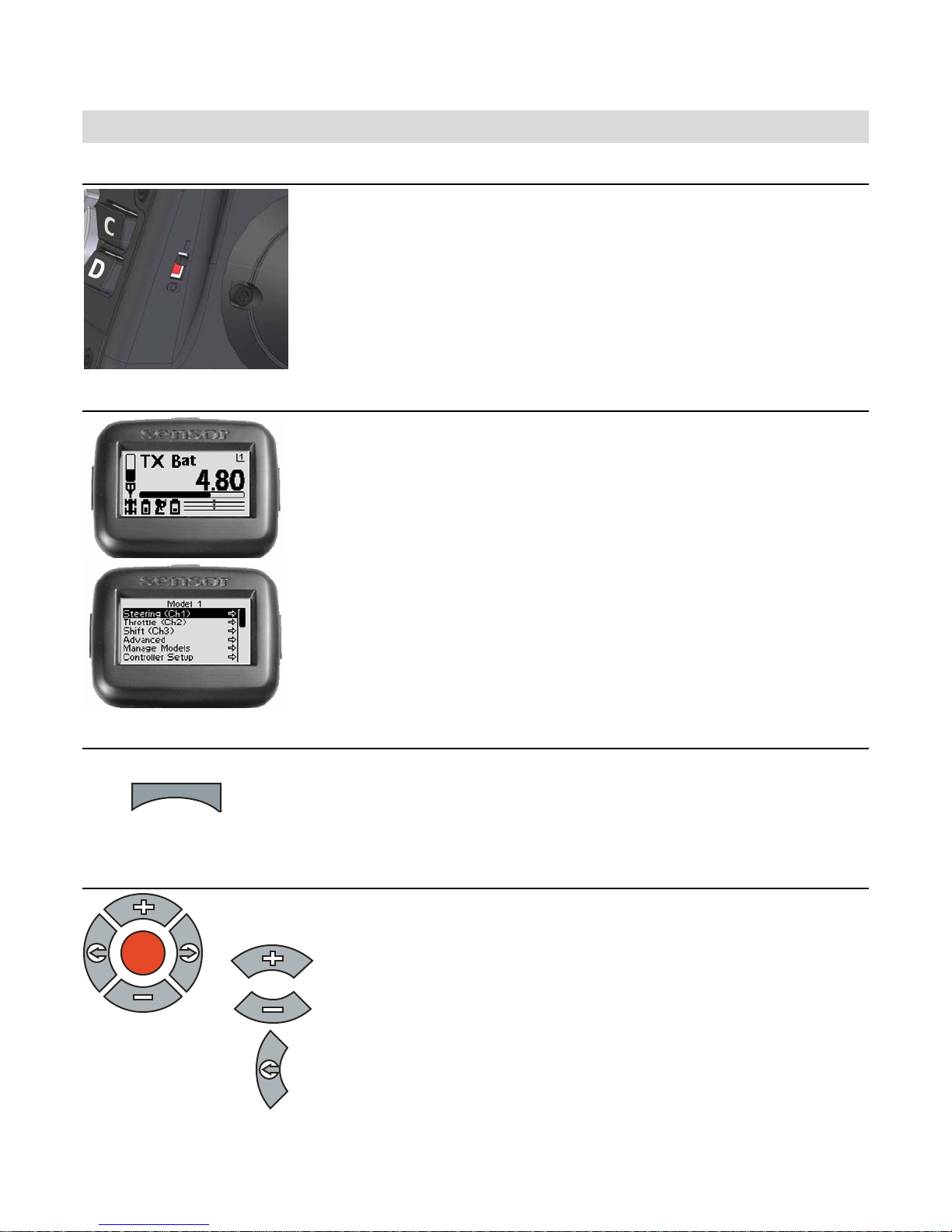
Power Switch
This switch turns the Sensor on and off.
Display Screen
Driv ing screen
This is the screen you’ll be seeing 95% of the time
while using the Se nsor. It displays radio a n d battery
status, telemetry data that you select, and your
se rvo informa tion.
Menu Button
men
Navigation Buttons
Button In the drivi ng screen In the function menu
OK
This screen is the gateway to the Sensor’s menu
Menu screen
Pressing this button toggles Sensor between the driving screen
and the top level function menu, or returns to the pre vious
level from a sub-menu.
Moves to next higher me nu item.
system, which is described in detail later. You can
a lways go back to the driving scr een by just
pre ssing the me nu key.
Moves to ne xt l ower menu item.
Displays previous reading. Decreases selected value.
3
Page 7
OK
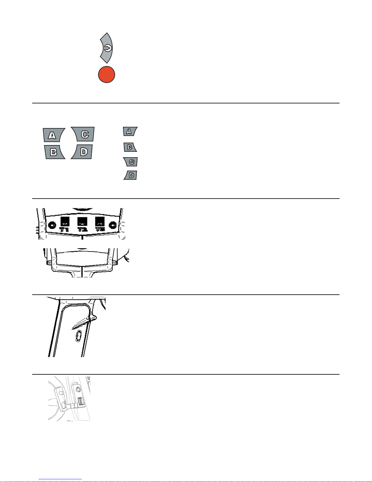
Selection Buttons
Trim Buttons
Displays next reading.
In the function menu
Sets the currently edited value to its maximum
value.
Sets the currently edited value to its minimum
value.
Cancels any changes made and resets value to
where it was before you started editing.
Resets the value to the factory default
• Increases selected value.
• Goe s to next sub-menu.
• Goes to selected sub-menu
• Saves the change to the
selec t ed set ti n g .
Grip Buttons
Connection Ports
T1 Adjusts the throttle dual rate setting.
T2 Adjusts the steering dual rate setting.
Left steering trim
Right steering trim
Performs shi fting ac tion on chann el 3.
Headphone
port
T3 Adjusts the throttle trim setting.
button
button
Accepts a 1/8” stereo headphone jack. The
output is the same in each ear (mono).
Adjusts the steering trim to the left or
right
Adjusts the steering trim to the left or
right.
Computer port
This connects to the USB port of your
comput er using the supplied ca ble.
4
Page 8
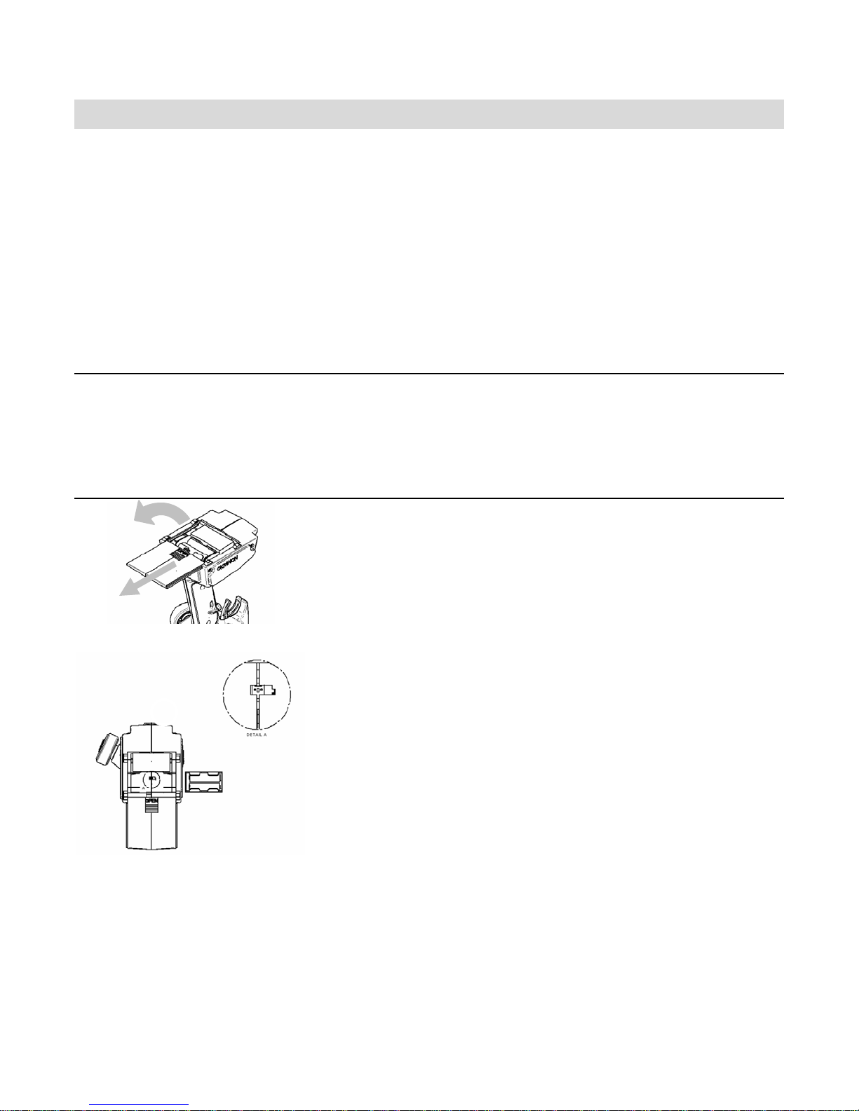
Chargin g and Installin g Batteries
The Sensor is powere d by four AA-size batterie s (1.2~1.5V). You may use the four AA-size
1.2V NiMH batt eries provided with t he Sensor, or you may use AA-size alkaline batt eries
(1.5V). Before using your Sensor, make sure the batterie s are fully charged.
The Sensor is reverse voltage protected: installing batterie s backwards cannot damage it. If
the batteries are backwards, simply reverse the battery connector.
Also inside the battery compartment is the 4 wire Receiver Programming Cable. This cable
can be plugged into the receiver’s TACH pins in order to upgrade the software on the receiver.
The R C Des ktop will instruct yo u when a soft war e u pgr ade is ava ilable.
Charging the Supplied NiMH Batteries
When using t he supplied NiMH batteries, charge the batteries for 12-14 hours (using the
supplied charger) befo re u sin g t he Sensor. Be sure t o get the polarit y correct whe n in st all in g
th e batt eri es i nt o th e ch a rger .
Installing the Batteries
1. Slide and remove the battery compartment cover at the bottom of the
Sensor.
2. Remove the battery holder.
NOTE:
The battery holder wires connect to a receptacle in the battery compartment.
It is no t necessary to unplug the connector when you remove the battery holde r.
However, if you do unplug the connector, note its orientation first.
in wrong, your Sensor will not turn on - no damage will be done to your
Se nsor, just remove and reverse it.
3. Install the batteries in the battery holder. Observe proper polarity.
4. Plug the battery holder connector into the receptacle in the battery
compartment.
5. Place the battery holder in the battery c ompartment. Make sure the
wires do not pinch.
6. Slide the battery compartment cover into place.
If you plug it
5
Page 9
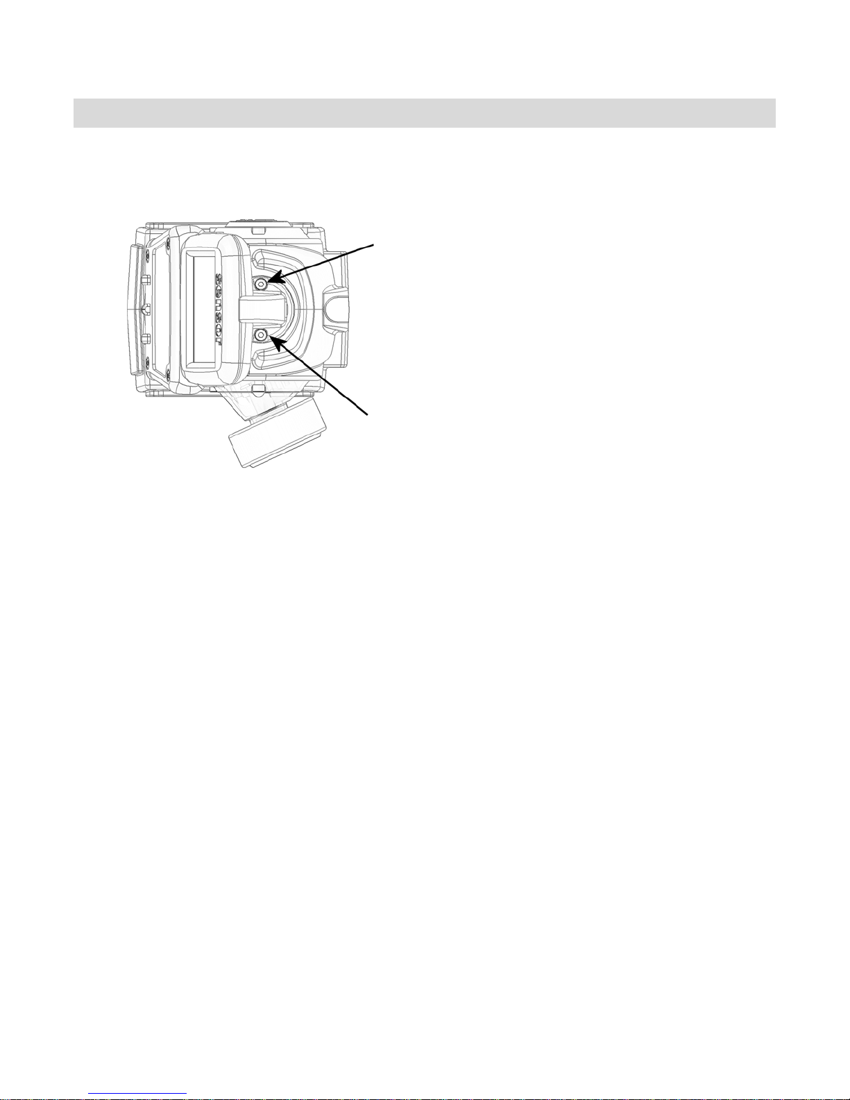
Adjust in g the Screen
Th e dis p lay sc r een at the to p of th e S e n s or can be repos iti on e d f or easi er vie wi n g.
Tools needed:
7/ 64” h ex wren ch
1. Make su re Se nsor is turned of f befo re
moving t he screen.
2. Using the hex w rench, loosen the two
screws holding the display screen.
3. Reposition the disp lay screen .
4. Retighten the screws
6
Page 10
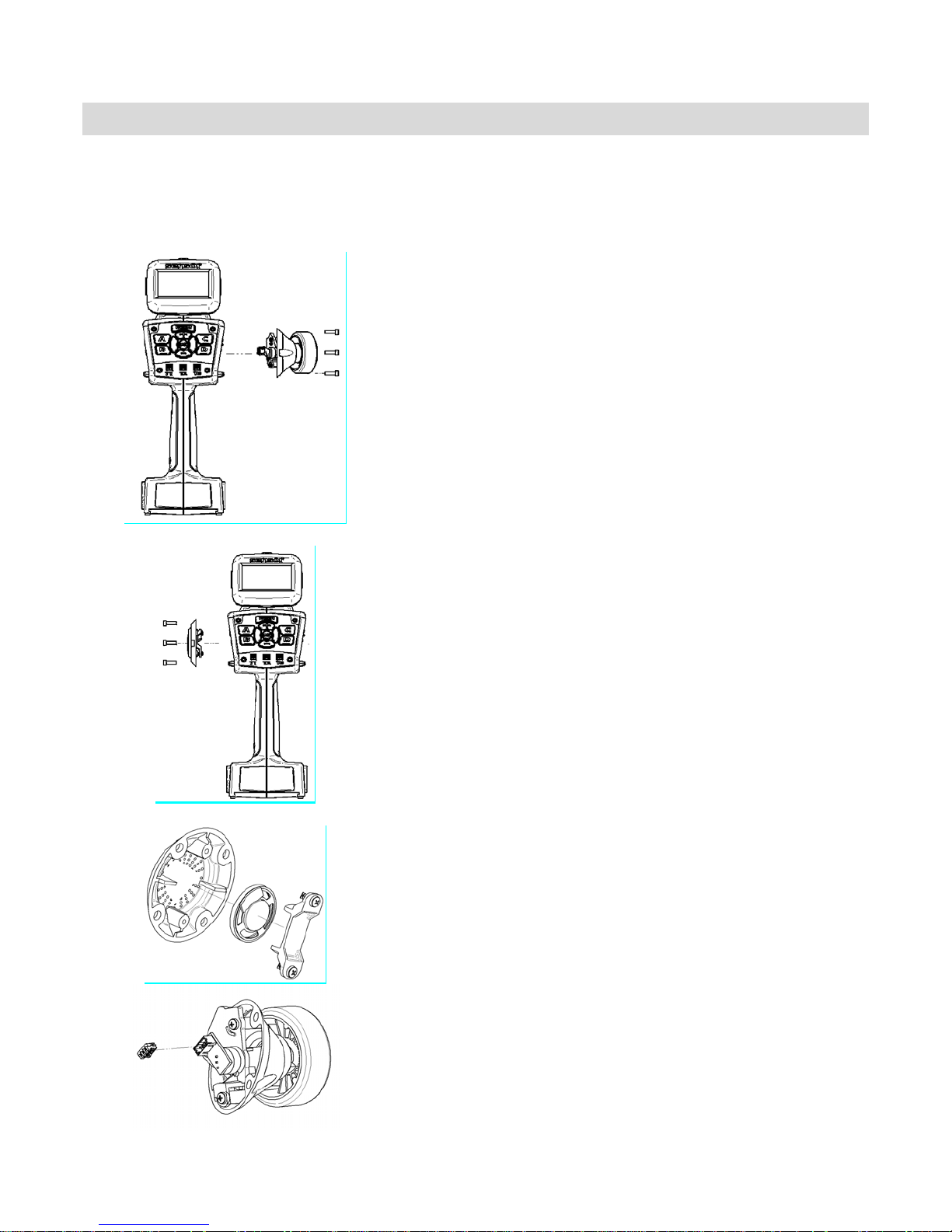
Convertin g for Left Handed Use
You can ea sily conv ert th e Sensor to lef t-ha nd ed use .
7/6 4” hex wr en ch
A : Remo v e t h e St eering Wh eel A ssembly
A1: Mak e sure th e S ensor is tu rned off
A2. Carefully remove t he Nomadio emble m in the
center of th e steering whe el. I t is held in place by
fr iction a nd p ulls towar d you, it does not twist.
A3. U se t he Ph il lips sc rewdriver to loosen and remove
the screw holding the steering wheel. Remove the
steering wheel.
A4. Use the h e x wre n ch to r emove t h e thre e s c rews
holding the steering wheel assembly.
A5. C a refully pull the s teering wheel a s sembly a way
from the Sensor body.
A6. Carefully unplug t he connector from the steering
wheel a ssembly .
B: Remove the Speaker Assembly
B1. Use t he hex wrench to remove the four screws
holding the s p eaker a s sembly.
B2. Pu ll th e speake r assembly away from the Sensor
body.
B3. U se t he Phillips screwdriver t o remove the tw o
s peaker cla m p s cre ws h olding the spea k er t o the pla s ti c
cover.
Tools needed:
#2 Ph il lips screwd river,
C: Swap the Assemblies
C1 . P ass t he st eering wheel co nnector wire t hrough the
S en sor body so it co m es o ut the LEF T sid e ho le (w here
the speaker used to be).
C2 . P ass t he speake r t hrough the Sensor body so it
comes out the RIGHT side hole (where the steering
whe e l u sed to b e) .
7
Page 11
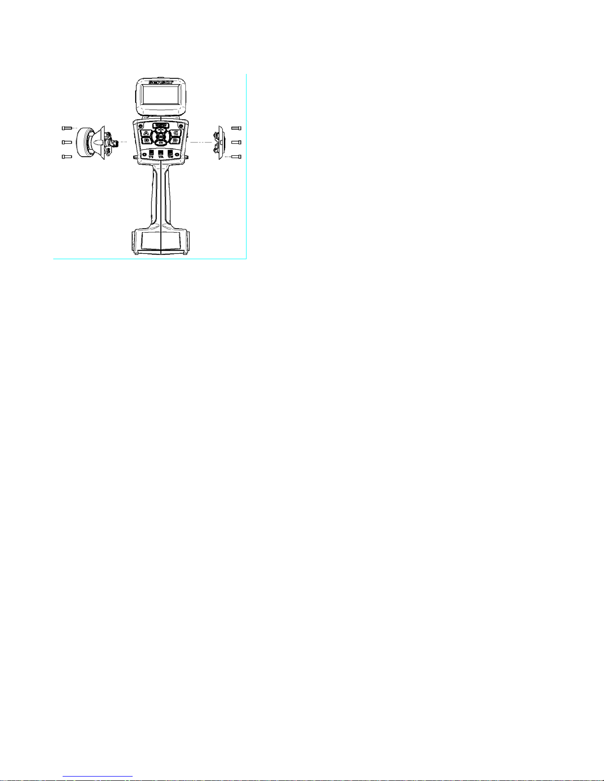
D: Re-assemb le
D1. Reattach the speaker to the plastic cover using the
two screws. Be careful not to over tighten and break
the speaker clamp.
D 2. R e co n n e ct th e steeri ng w heel wi re co nnec t or to th e
steering wheel.
D3. Reatta ch the speaker assembly to t he RIGH T sid e
of the Se nsor body.
D4. Reattach the steering wheel assembly to the LEFT
s i de of th e Sens or body .
D5. Reattach the steering wheel.
Make s ur e the steering wheel has full left-and-r ight
movement.
D6. Reinsert the Nomadio emblem in the center of the
steering wheel.
8
Page 12
Installin g the Transceiver
Mounting the Transceiver
• Install the transceiver so it is protected from vibration or shock.
• Use double-sided tape or Velcro® to mount the transceiver.
• Position the transceiver where it will not contact other solid components.
• Mount the transceiver away from moving parts, sharp corners, and possible contaminants (fuel, dirt,
etc.).
• When possible, waterproof and protect the transceiver by wr apping it in f oam rubber and placing it in a
rubber ball oon or plastic bag. I f you accidental ly get moisture or fu el inside the transceiver, inte rmittent
or erratic operation m ay result.
• Position the transceiver so the sensors can be easily connected to it.
Antenna
• The thinner portion at the end of the antenna wire must be outside the vehicle body
• DO N OT CUT the ante nna wire
Connecting the Transceiver
Servo Co nnect ion
Servo Input Plugs
The transceiver is designed to use Futaba J-style input plugs
with wiring order as show n in the diagra m.
Se rvo lead wires MUST be i n this order. If the servo wire s are
i n a different order, you must re-order the wires in the input
plug. Check with your servo manufacturer about the color and
order of the servo lead wiring.
When you insert the servo input plug into the transceiver, note
that the input plug may have an alignment tab. Orient the
a lignment tab prope rly before inserting the input pl ug.
To remove in input plug from the transceiver, pull the input
plug rather than the servo wires.
C o n nect t h e s e r vos to the a pp ro p ria te po sition s in the tr ansceiv er:
C onne c t… …into transc eiv er receptacle
Receiver battery “Power”
Steering servo “Steering”
Throttle servo or ESC “Throttle”
Shi fting se rvo “Shft/CH3”
9
Page 13
Installin g the Sensors
Your Sensor radio sy st em come s with sev eral se nsors that you ca n install in y ou r v ehic le and
connect to the transceiver. When properly installed and connected, these sensors w ill send
information back to the Sensor so that you can monitor the readings while you drive.
Receiver Battery Sensor
The t ransceiver monitors the receiver battery voltage from the POWER receptacle. T here is no
instal lation necessary f or th is sensor.
Voltage Sensor
The voltage sensor is used to monit or the voltage of a separat e battery pack (for example, an
electric ca r’s main ba ttery pack). In a Nitr o car , this sensor is not needed.
1. Connect the RED wire of voltage sense to t he posit ive
terminal of your battery pack and the BLACK wire of the
voltage sense to the negative terminal of the battery pack
you want to m oni tor .
2 . C arefully route, prot ect, and secure t he sen sor wire s.
3. Plug the voltage sensor into the BATT receptacle.
Temperature Sensor
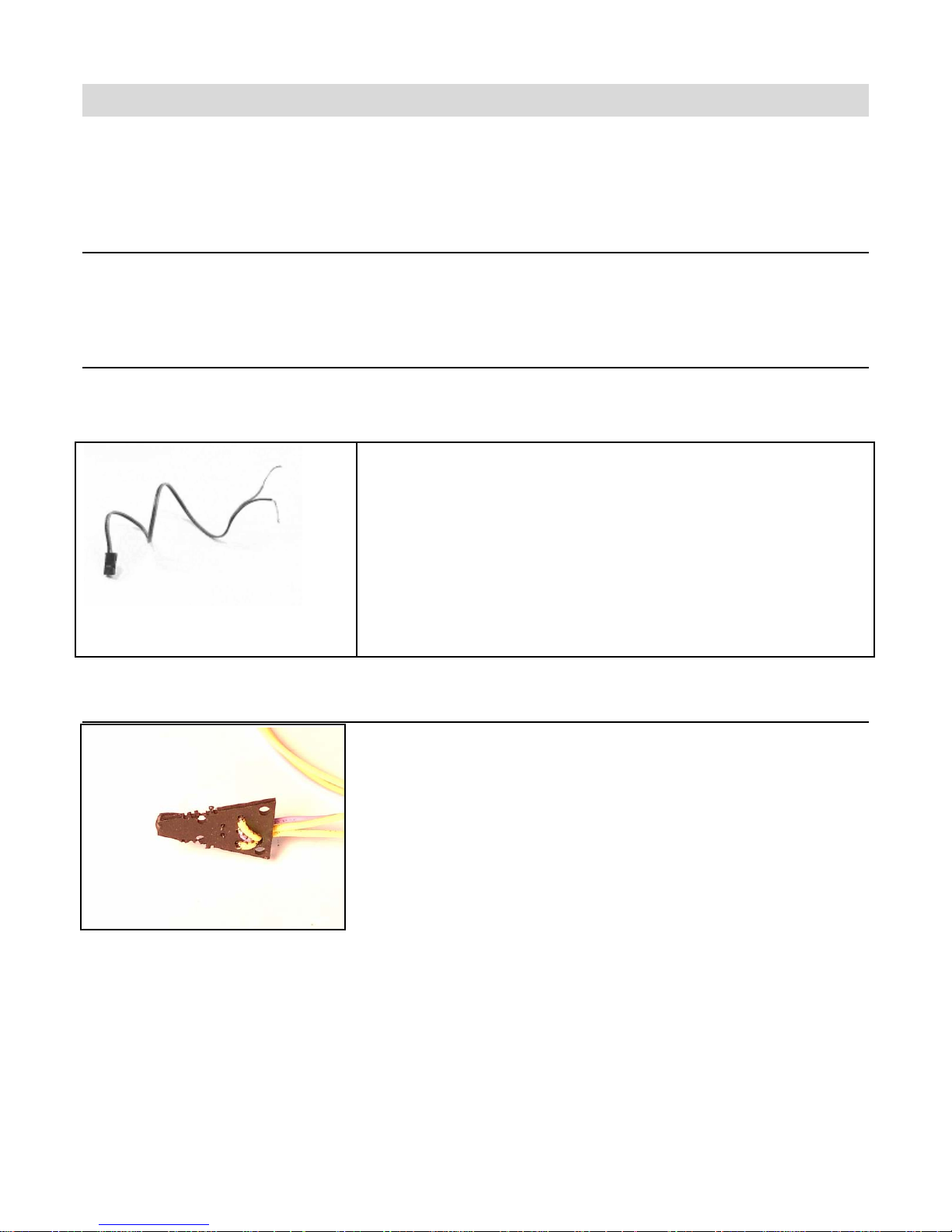
The temperature sensor is used to monit or the temperature
of a vehicle component such as a main battery pack, electric
motor, o r nitro engine.
Installation
The tip of the triangular temperature sensor is the active
measuring element. Install the sensor so that this tip is
pr ess ed ag a ins t the i t em whos e t em per a t ure you wish to
measure.
T he sensor has been designed to be thin enough to fit between the fins on a heat sink. Two
sets of holes ar e provided to wire-tie the se nsor in place if desired. Alternately, a high-
temperat ure epoxy may be used to secure the sensor.
Whe n installin g on a nitro motor, place the sensor as low as possible on the head, op posite
the exhaust port. The sensor may also be inst alled on an elect ric motor, batt e ry pack, or ESC
heat sink.
10
Page 14
Connect ion
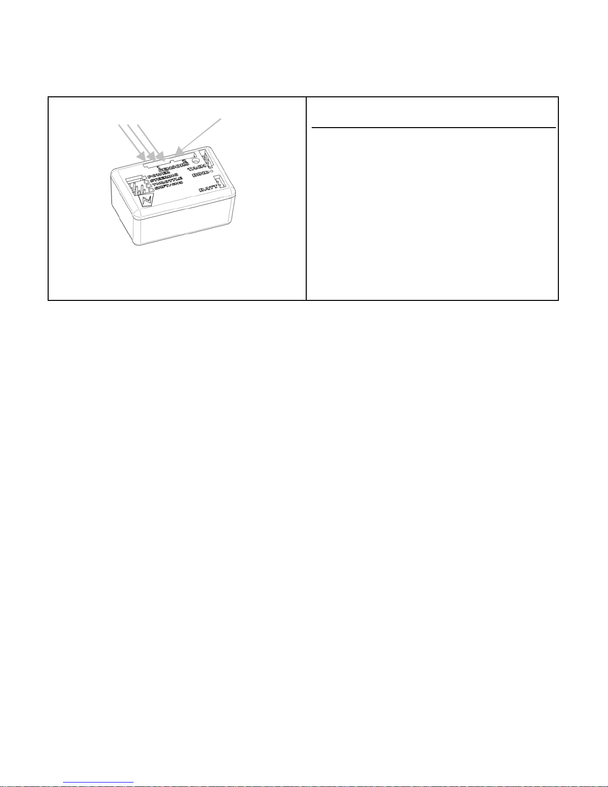
Connected Pins
Unused Pin
Connecting the Temperat ure Sensor
Aft er you install the temp eratur e sensor in
the vehicle, plug it into t he “Sensor 1” or
“Sen sor 2” re ceptacle.
The four-pin connector on the sensor cable
has only three w ires populated. The
unpo pul a ted pi n shoul d be the one furth est
from the connector key in the receiver
plastic.
The S e n sor tr an s c e iv er wil l a u to m aticall y
d et ect wh ic h sensors are installe d.
11
Page 15
Bind in g the Transceiver
The binding process “locks” the Sensor and a transceiver together so that they listen only to
ea ch o ther .
Since the Sensor has eight model memories, it is po ssible that your Se nsor will be used to
co m mun icate with eight tr an s ceive r s. Yo u mu st there f o r e p e rfo rm the b ind ing pro c ess once for
each tr ansceiver that will communicate with your Sens or .
N o t e that the Sen s o r cann ot com mun ic ate with a ll of the tra n s c e iv ers at the s am e tim e, but
rather the Sensor will communicate only with the transceiver associated with the Sensor’s
currently a c tive mo del. Fo r more infor matio n, s e e “Ma naging Models ” later in this instruc tion
manual.
How the Binding Process Works
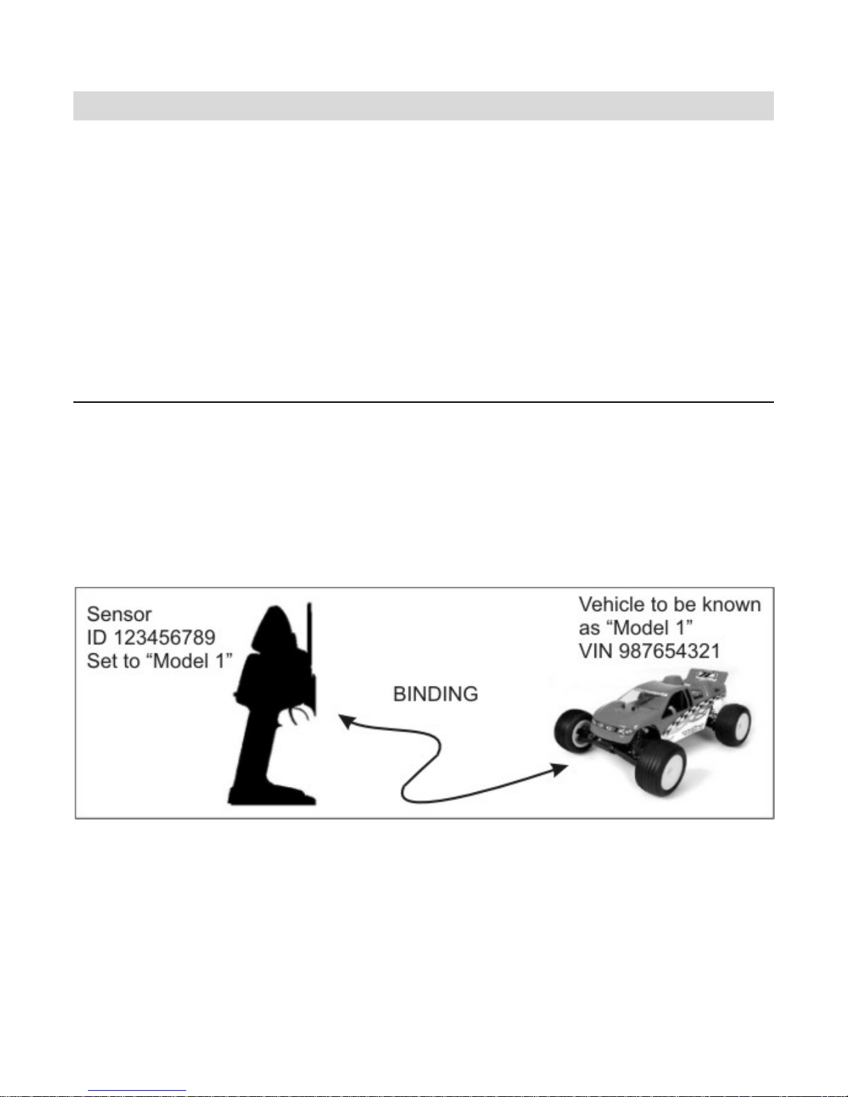
The binding proce ss is set in mot ion by depressing the “bind” button on the transceiver when
the Sensor is in “bind mode .” The transceiver broadcasts an inquiry message, indicating that it
is looking for a Sensor to bind to.
Th e S e nsor r es p o n ds back to the tra n s c eiver , i n dicati n g i ts I D number (f or exa m p le, th e
Sens or I D ma y b e 12 345 67 89). The tra ns ceiver res p onds back t o the Se nsor, i ndi ca ti n g i ts
o wn VIN num ber (for exam pl e, th e VIN may be 9876 54 32 1). Af t er tha t, th e bi nding process i s
complete.
12
Page 16
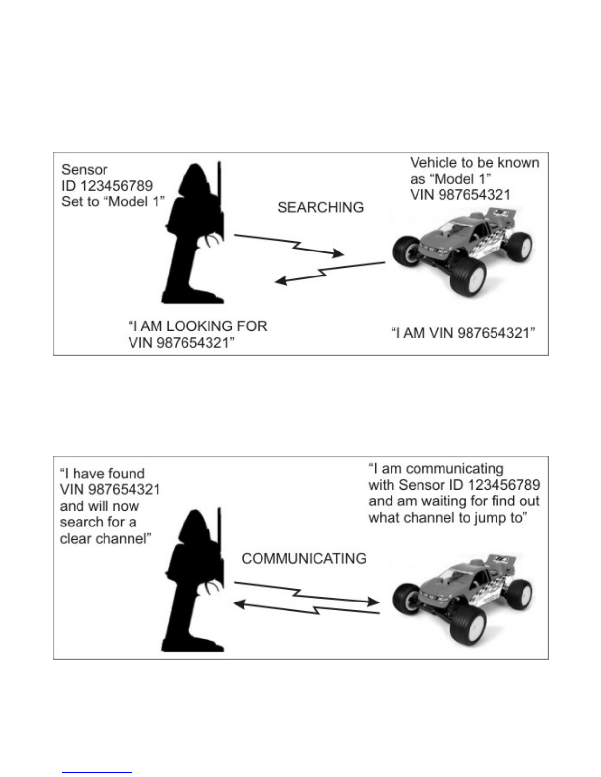
Now, every time you turn on the Sensor and set it to the appropriate model ID (see “Managing
Models” later in this ma nual), the Sensor go es to a spe cia l “lookup c ha nnel” a nd se ar ches for
messages f rom the approp riate VIN.
Wh en yo u tur n on t h e ve h i c le’s tr a n s ceiv er , t h e tr a n s c eiver g oes t o th e l ook up ch a nnel an d
broadcast s its VIN so it can be found by the appropriate Sensor.
Wh en th e S ensor find s t he ap pr opr ia te VI N , the co n nec ti o n i s m a de. Th e S ens o r t h e n sear ches
for a clear frequency channel; when one is found, the Sensor “tells” the transceiver to jump to
that clear frequency channel.
13
Page 17

Binding your transceiver the first time
1 . Install a transceiver in to y our ve hicle .
(For this example, ins tall a tra nsceiver into your electric tour ing ca r, w hich will be known to
the Sensor as “Model 1.”)
2. In the Sensor’s “Manage Models” function menu, go to “Active Model” and select the
appropriate mode l ID for the vehicle you are going to bind to . (For this example, select “Model
1.”)
3. After putting your model on a st and to prevent runaw ays, powe r up the vehicle and
transceiver.
4. Br ing the Senso r clos e to the model. This will help the tra nsc eiver and Sensor to “find”
each ot her more easily.
5. In the Sensor’s “Manage Models” function menu, select “Rebind . ”
6. Using an extended paperclip, depress and ho ld the transceiver’s “bind” button until the
onboa r d LED illuminates.
7: Confirm binding on your Sensor by pressing the “O K”as the transceiver VIN numbe r is
displayed.
T he binding process is now complete!
14
Page 18
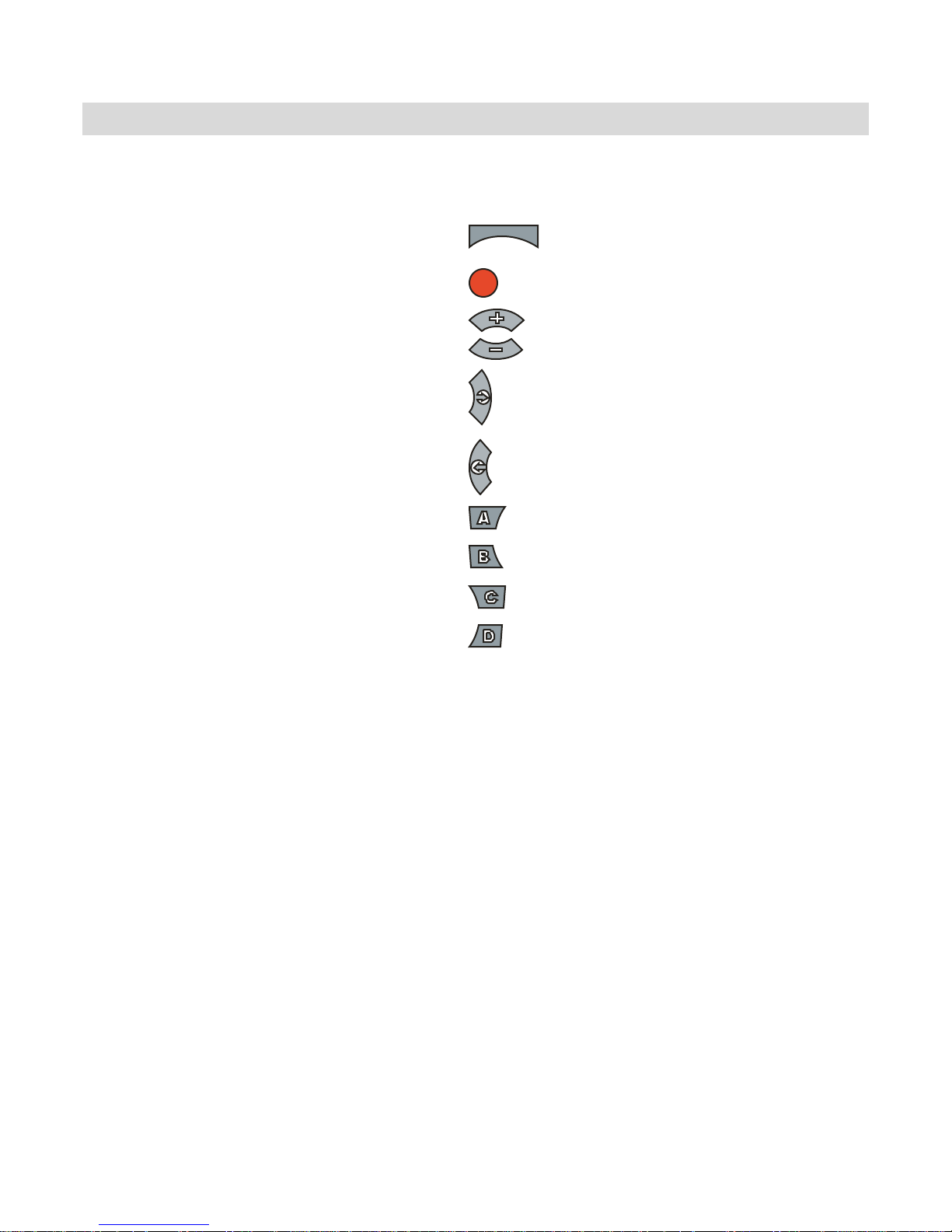
Sensor Controls
T he functions of the Sensor are controlled through the function menu and/o r trim controls.
To perform this action… Press…
Toggles between the driving screen and the function
menu or returns to the previous level from a submenu
menu
Menu: Go to t he sele cted sub-menu
Menu: Move to t he next higher me nu item.
Menu: Move to the next lower menu ite m.
Menu: Go to t he sele cted sub-menu.
Drive: Display next statist ic.
Menu: Decrease the selected value setting.
Drive: Display previous statistic.
Menu: Set currently edited value to maximum.
Menu: Set currently edited value to minimum.
Menu: Cancel cha nges made to the current
parameter.
Menu: Reset current ly edite d value to factory defa ult.
OK
15
Page 19
A
Top Menu Level
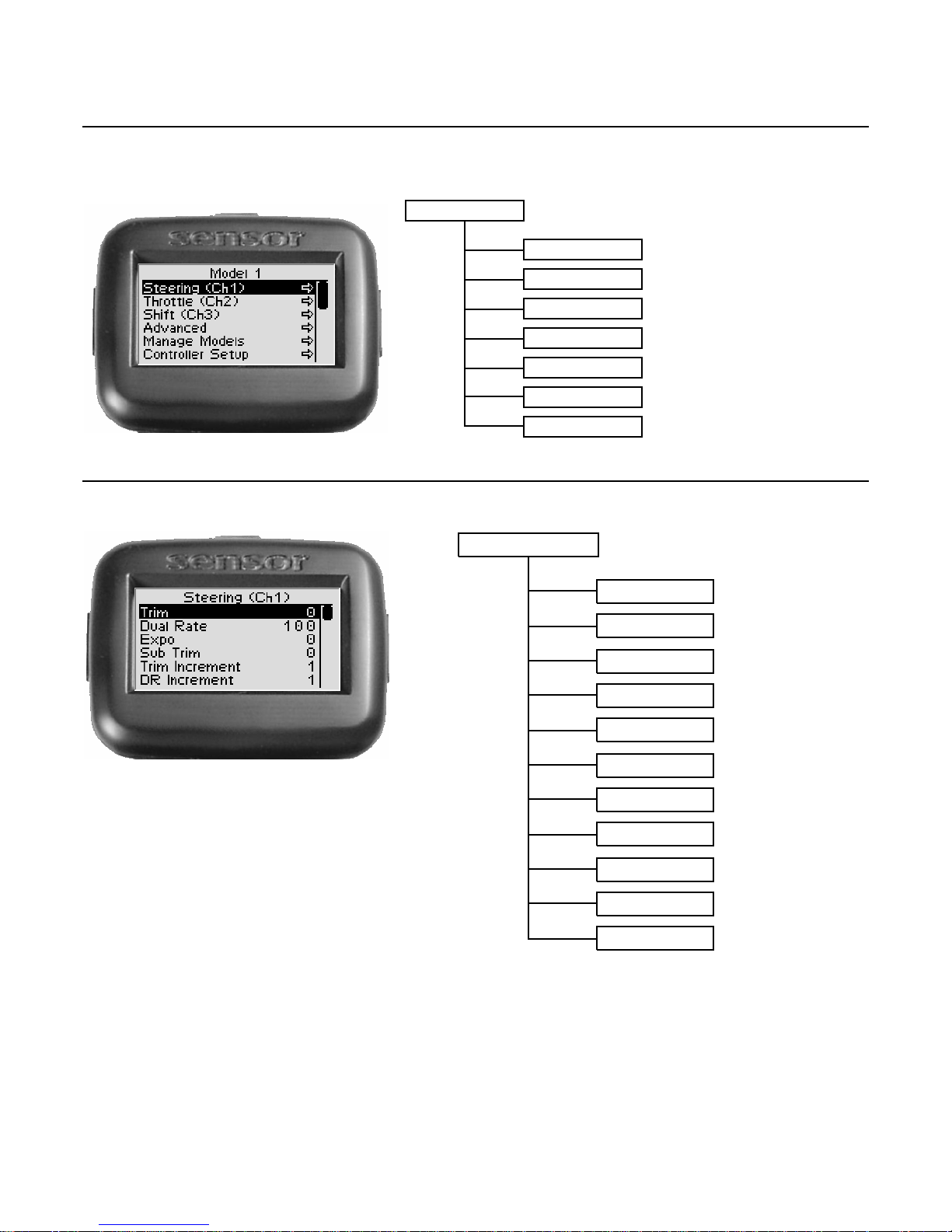
The following illustration shows the func tion me nu str ucture fo r the top level menu. All ma in
sub-menus may be accesse d fro m the top menu level.
Top Level Menu
St e e rin g ( C h 1)
Throttle (Ch2)
Shift (Ch3)
Advanced
Ma nage Models
Controller Setu p
Statistics
Steering Functions
The following illustration shows the func tion me nu str ucture fo r the steer ing functions:
Steering ( Ch 1 )
Dual Ra te
Expo
Sub Trim
Trim Increment 1 -
DR Increment
Left End Point
Ri gh t E nd P o i n t
S ervo Reve rs e
Trim
- 100 to 100
0 -
100
- 100 to 100
- 100 to 100
20
1 -
20
0 to 100
0 to 100
Off , On
16
Servo Type
Servo Speed Input,Return,Trigger
nalog , Digital
,
Page 20
S tee ring Tr im
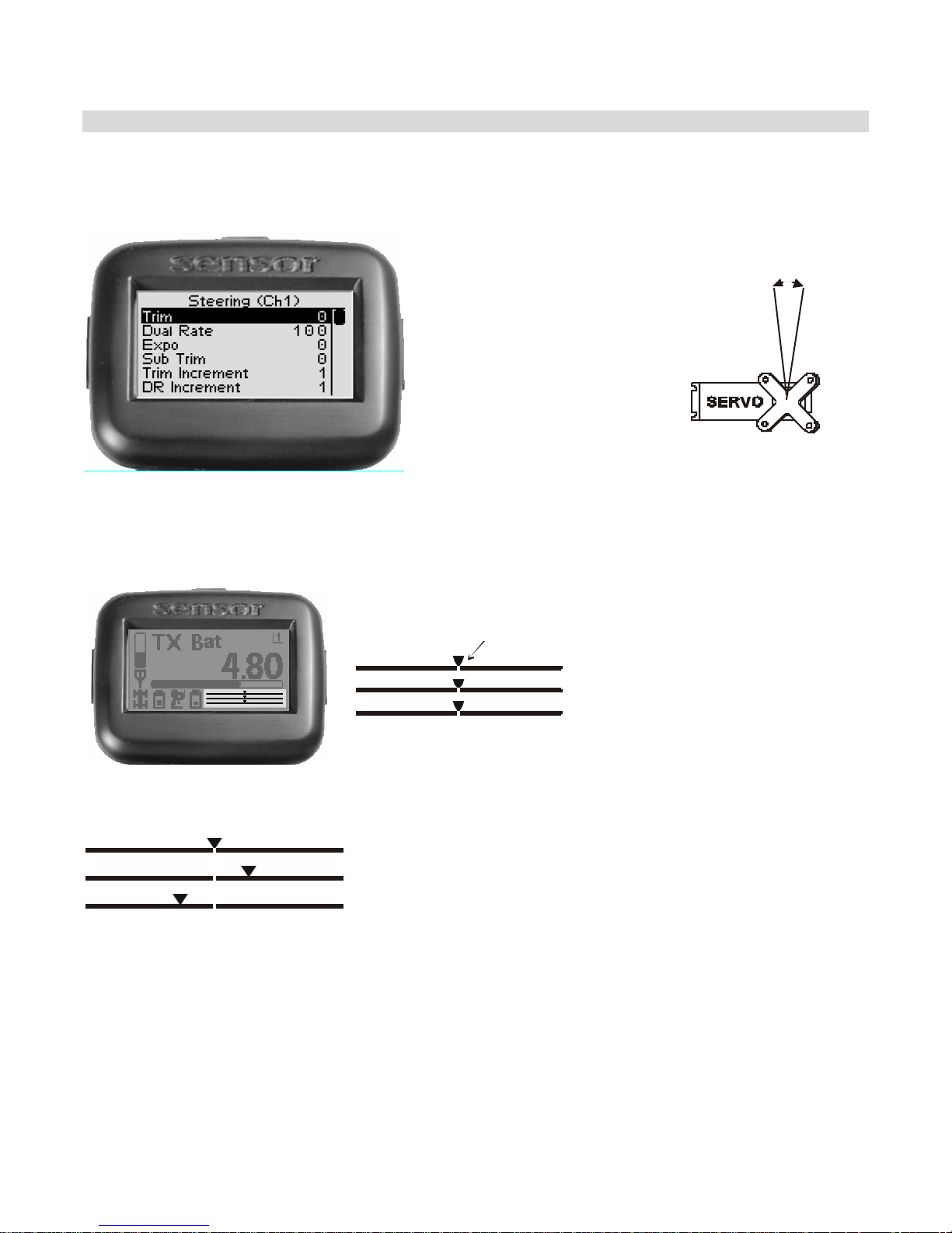
Steerin g trim adjusts the
center point of the steering
servo by adjusting the
center point within the
steering servo’s t otal travel
range. Unlike steering sub-
trim, t he st eering left and
r i ght end poi n ts ar e
unaffected by steering t rim;
by mo v ing t he cen t er poi nt
o f t he st eering servo u sin g
trim, the center position
moves closer to one end
poi nt or the o th er.
Ste ering tr im s hould be
used o nly after you have
initially adjusted steering
sub-t rim.
Steering Trim
Steering (Ch1)
Throttle (Ch2)
Shift (Ch3)
On the dri ving screen,
steering trim is represented
by the position of the
poin ter on the upper bar.
As you c ha nge the ste ering trim, it is shown gr aphically on the d r iving scr een tr im indicato r
bars:
Steering trim is centered in range (value = 0)
Steering trim is offset to the RIGHT (+ve value)
Steering trim is offset to the LEFT (-ve value)
If you find that you have to use a large amount of steering t rim to get the vehicle to
dr ive straight , you s hould cons ider res e tting the s teer ing tr im to 0 and re-adjusting the
serv o horn on t he servo output shaft .
17
Page 21
Ad j ust ing Ste e r ing T r im using the Fu nctio n Me nu
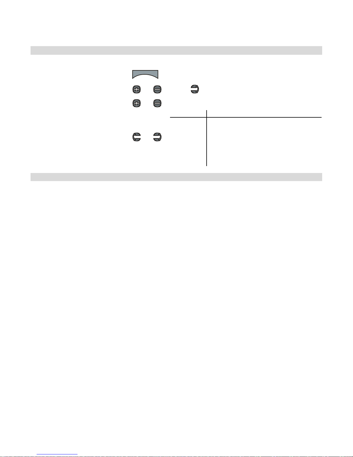
Use the navigation controls to adjust steering trim as follows:
1. Access the top function menu
from the driving screen.
2. Navigate to the Steering (Ch1)
menu.
3. Navigate to Trim.
4. Change the value.
menu
or : then
or
or
Value Description
0 Steering trim is centered within the servo
-ve value
(-100 Æ -
1)
+ve value
(1 Æ 100)
range.
Steering trim is to the LEFT.
Steering trim is to the RIGHT.
Ad j ust ing Ste e r ing T r im using the Ste e r ing T r im B uttons
You can use the steering trim buttons on the left and right sides of the Sensor to adjust steering trim. Push the
trim button forward to adva nce the trim, backward to reduce it. If you have a sound attached to the trim
adjustment you will hear the sound each time the trim is changed.
A trim (or s ub-trim ) s e t ting of 100 is e quiva le nt to a n E nd P oint s e t ting of 20.
18
Page 22
Steering Dual Rat e
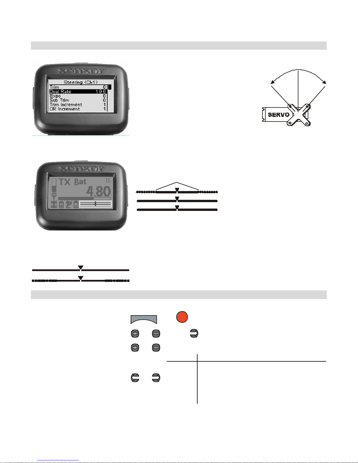
Steerin g dual rate ad justs the range o f
servo movement when the s teering
wheel is fully turned in either the left
or r ight d irection. This is used to
increase or decrease the steering
sensitivity acros s the e n tire ser vo
range. The st eering dual rate value is
applied to both left and right side s,
and is expressed as a pe rcentage of
serv o range (conf ig ured by end po in t
adjustments).
On the dri ving screen,
steering dual rate range is
represented by the solid
Dual Rat e Range
Steering (Ch1)
Throttle (Ch2)
Shift (Ch3)
length of the upper bar.
The total length of the bar
(sol id and dotted)
represents the servo
range. The length of the
solid bar represents the
range set by the dual rate
value.
As you c ha nge the d ual ra te settin g it is s hown gra phically on the d r iving scr een tr im indicato r
bars:
Full servo range is used.
Lowe r dual ra te value reduces servo range.
Adjust ing Steering Dual Rat e using the Funct ion Menu
Use the navigat ion controls to adjust steering dual rate as fo llows:
1. Access the top function menu
from the driving screen.
2. Navigate to the Steering (Ch1)
menu.
3. Navigate to Dual Rate.
4. Change the value.
menu
or : then
or
or
OK
or
Value Description
0 Steering servo range is set to minimum (0%).
1-99
100 Steering servo range is set to full (100%)
19
Steering servo range is set to a percentage of
full range.
For example, value “50” gives 50% of full
s ervo range .
Page 23
Ad j ust ing Ste e r ing Dual Rat e u s ing th e T r im B utton
You can also use the T2 trim button to adjust the steering dual rate.
Dual Rate and End Point Adjust ment
Full servo range is dete rmined by the le ft and right end point adjust ments. The dual rat e value
d et ermines the relative se rv o ran ge between t he left and right end points. The servo will n ever
move be yond the set end po int adjust ment s, no matter what dual rate setting is applied.
S tee r ing E x ponentia l
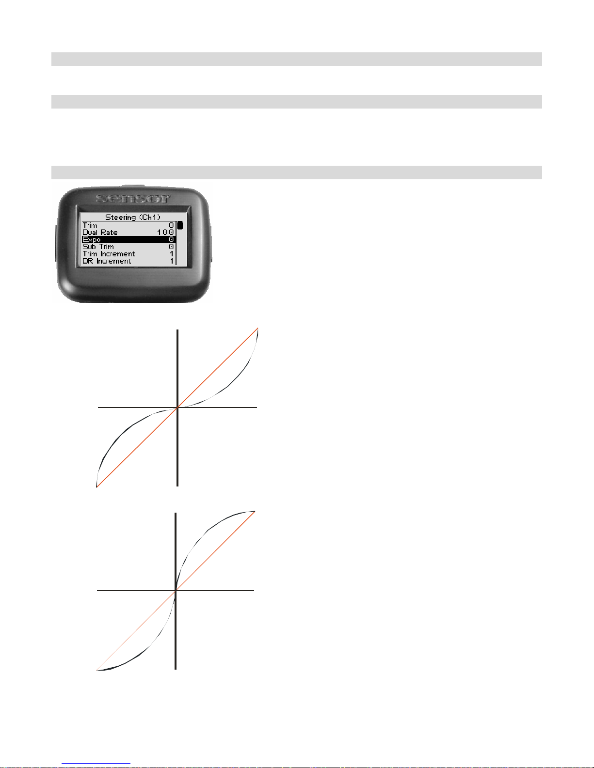
Steerin g exponential adju sts how quick ly or slowly t he
steering servo responds with respect to the amount tha t the
steering whe el is turned. T his affects the s ensitivity of the
steering servo near its neutral positio n (center).
Adjusting the steering exponential value affects both left and
right steering response at the same rate.
Servo trav el
RIGHT
-ve exponen t i al
(milder resp onse)
Steer ing w hee l
tur ned full LEFT
+ ve exponential
(quicker response)
Steerin g whee l
turned f u ll LEFT
Neutral
Servo trav el
LEFT
Servo travel
RIG HT
Neutral
0% ( linear )
1~100%
(quick)
0% ( li near)
-1 ~ -100%
(mild )
Ste ering w h eel
t ur ned ful l RIGH T
Steering w h eel
tu r n ed f ul l RIGH T
A neg ative (-ve ) exponential value g ives a
milder steering response near the steering
neutral point, m aking it LESS res p onsive to
steering in puts at t he st eering wheel.
A positive (+ve) exponential value g ives a
q uic k er steering respo nse near t he steering
neutral point, m aking it MORE responsive
to steering inputs at the steering wheel.
Servo travel
LEFT
20
Page 24
Ad j ust ing Ste e r ing E x pon ential
U se the naviga tion controls to adjust s teer ing exponentia l as follows:
1. Access the top function menu from
the driving screen.
2. Navigate to the Steering (Ch1)
menu.
3. Navigate to Expo.
4. Change the value.
menu
or : then
or
or
Value Description
0 Neutral steering response (linear).
-ve value
(-1 to -
100)
+ve value
(1 to 100)
Milder steering response near
center.
Quicker steering response near
center.
Steering Sub-Trim
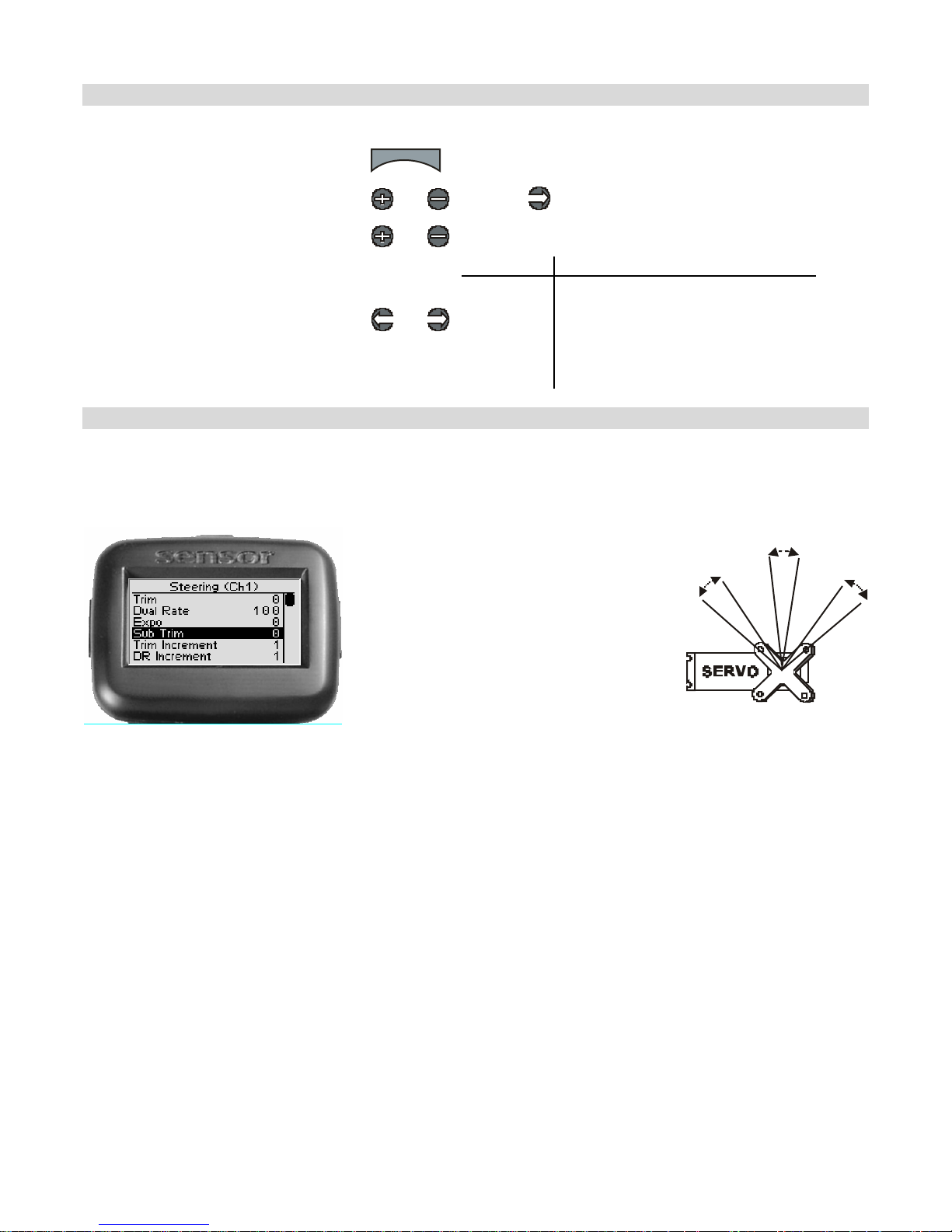
Steerin g su b-trim adjusts the center
p oin t of the st eering servo. This
differs from steering trim in th at
steering sub-trim ad justs t he servo’s
en tir e tr a v el range; b y mo ving t he
center point of the servo, the left and
right end po int s (le ft, right) stay t he
sa me rela tive “distance” from t he
serv o center.
Ste ering sub-trim s hould be initially
ad justed after you h av e assem bled
your v ehicle’s st eering sy st em; aft er
you begin driving t he ve hicle , use
steering trim to make fine
a djus tm e nts to c e nter the steer ing
within the to tal s teering ra nge.
If you find that you have to use a large amount of ste e ring sub-t rim to get the vehicle
to dr ive straight, you s hould consider rese tting the steering s ub- trim to 0 and re-
ad justing the servo ho rn on the servo output shaft .
21
Page 25
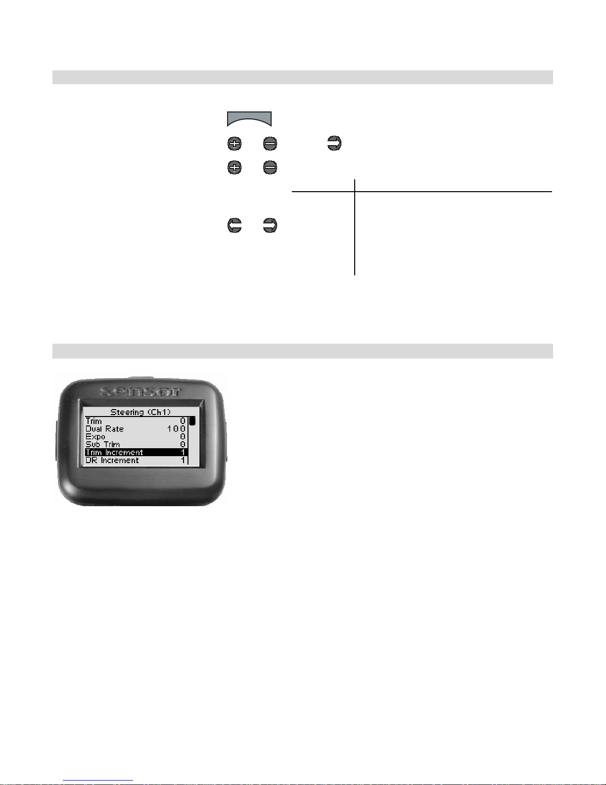
Ad j ust ing Ste e r ing Sub-tr im
Use the naviga tio n co ntrols to adjust st eering sub-t rim as follo ws:
1. Access the top function menu
from the driving screen.
2. Navigate to the Steering (Ch1)
menu.
3. Navigate to Sub Tri m.
4. Change the value.
menu
or : then
or
or
Value Description
0 Steering sub-trim is centered within the
-ve value
(-100 Æ -
1)
+ve value
(1 Æ 100)
s ervo range .
Steering sub-trim is to the LEFT.
Steering sub-trim is to the RIGHT.
Tri m and EPA In te ract ion
A trim (or sub-trim) setting of 100 is equivalent to an End Point setting of 20.
Steering Trim In crement
Steering trim increment adjusts the sensitivity of the
steering t rim buttons on the left and right sides of t he
Sen sor, by adjust ing the amo unt that the servo t rim valu e
increments for one “step” of adjustment.
For example, sett ing the t rim increment value t o “5”
ch anges the ste e r ing tr im value by 5 e a ch tim e that a
st eering trim button is pressed once.
Adjusting the steer ing tr im increment v alue affects both
left and right steering trim at the same rate.
22
Page 26
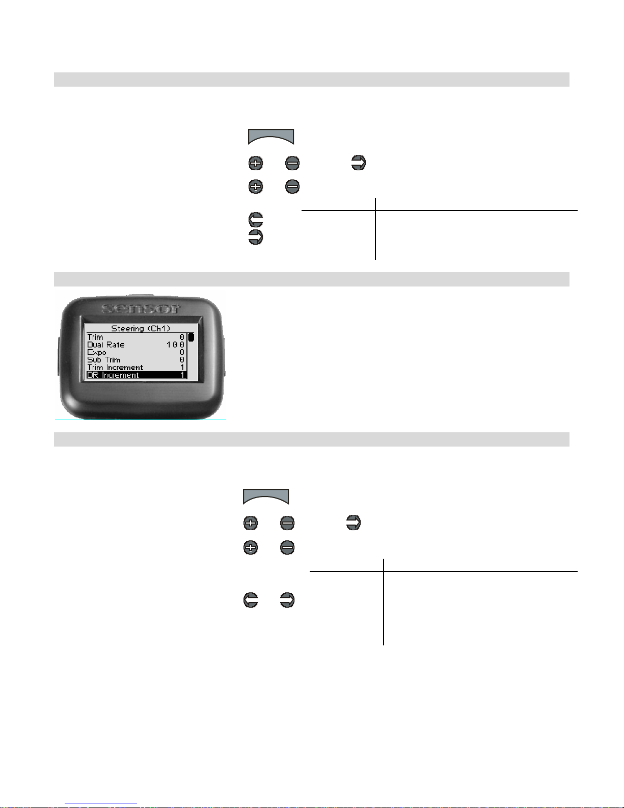
A d ju sting St eering Trim Incremen t
Use the navigat ion controls to adjust steering trim increment as follows:
1. Access the top function menu from
the driving screen.
2. Navigate to the Steering (Ch1)
menu.
3. Navigate to Trim Increment.
4. Change the value.
menu
or : then
or
or
Value Description
1-20
Steering trim value changes by set
increment.
Use smaller values for finer trim control.
Use larger values for coarser trim control.
Steering Dual Rat e Increment
Steering dual rate increment adjusts the sensitivit y of the
steering du al rate by adjusting the am ount dual rate value
increments for one “step” of adjustment.
For example, sett ing the dual rate increment value to “5”
changes the steering dual rate value by 5 each time that a
st eering dual rate t rim button is pressed once.
A d ju sting St eering Dual Rate Increment
Use the navigat ion controls to adjust steering dual rate increment as follows:
1. Access the top function menu from
the driving screen.
2. Navigate to the Steering (Ch1)
menu.
3. Navigate to DR Increment.
4. Change the value.
menu
or : then
or
or
Value Description
1-20
Ste ering dual rat e value changes by s et
increment.
Use smal ler value s for f iner dua l rate
control.
Use large r values f or coarser dual rate
control.
23
Page 27
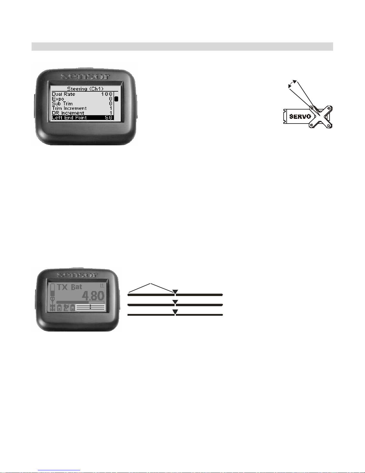
S tee ring L e ft E nd Point
The steering left end point value adjusts
how far the s teering servo turns to the
LEFT with respect to its full range of
m o tion to t h e l e ft. E nd po int a d j u stm ent
shou ld be adjust ed prior t o ot her st eering
sett ings, as the le ft end point value
affects other steering settings.
The left end point is set independently of
the right end point (which adjusts how
far the st eering servo tu rns t o t he
RIGHT).
The left end point settin g s hould b e used to do the following:
• Limit steering th row to reduce mech anic al b in din g or servo strain t hat m ay occu r on full
serv o t hrow to the left. For e xample, if t he servo is tryin g to tu rn the st eering sy st em t o
the left farther than it is m ec hanically able.
• Ad just ste e r ing th r ow to c hange st e ering c h a ra cteris tics when tu rnin g to the l e ft.
For example, if the current amount of steering throw to the left causes oversteer or
un d ers t eer w hen tur n i n g t o th e l eft.
On the dri ving screen,
the left end point is
represented by the
length of the bar to the
left of the pointer on the
Left End Point
S teeri ng (Ch1)
Throttle (Ch2)
Shift (Ch3)
upper ba r.
The greater the left
length of the bar, the
greater the left end
point value.
The position of the
pointer on the bar is
affected by the end
point settings (left
and right) and trim
settings.
24
Page 28
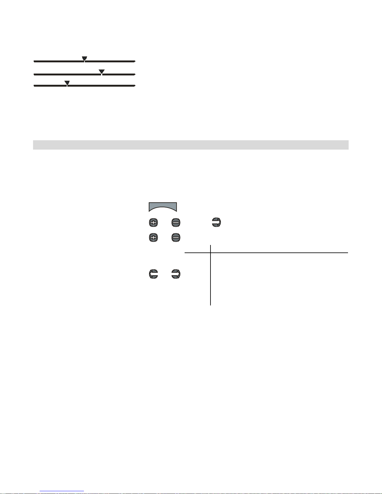
Changing the left end point value has the follow ing visual effect on the driving screen bars.
Left e nd point value is approximately the sam e as the right end point
value.
Increased left end point value (more servo travel to the left is possible).
Decreased left end point value (less servo tra vel to the left is possible).
Th e po s iti on of th e p oin t er on t he ba r i s af fect ed by the steer ing end p oint se t ti n gs (l eft
and right) and trim sett ing; increasing t he left end point value may visually appear to
have the same effect as decreasing the right end point value.
Ad j ust ing the Left End Point
The left end point va lue is a r elative value, and is express ed a s the per c entage o f full travel to
the left. For example, setting the left end point value to “50” allows the steering servo to turn
only 50% of full travel t o the left.
U se the na viga tion controls to a djust the left end point a s follows:
1. Access the top function menu from
the driving screen.
2. Navigate to the Steering (Ch1)
menu.
3. Navigate to Left End Point.
4. Change the value.
menu
or : then
or
or
Value Description
0
1-99
100
Minimum left end point; allows NO turning
motion to the left.
Left end point value is set to a percentage of
full le ft-turning range . For example, a value of
“50” gi ve s 50% of ful l left-turning range.
Maximum left end point; allows FULL leftt urning range.
Tri m and EPA In te ract ion
A trim (or sub-trim) setting of 100 is equivalent to an End Point setting of 20.
25
Page 29
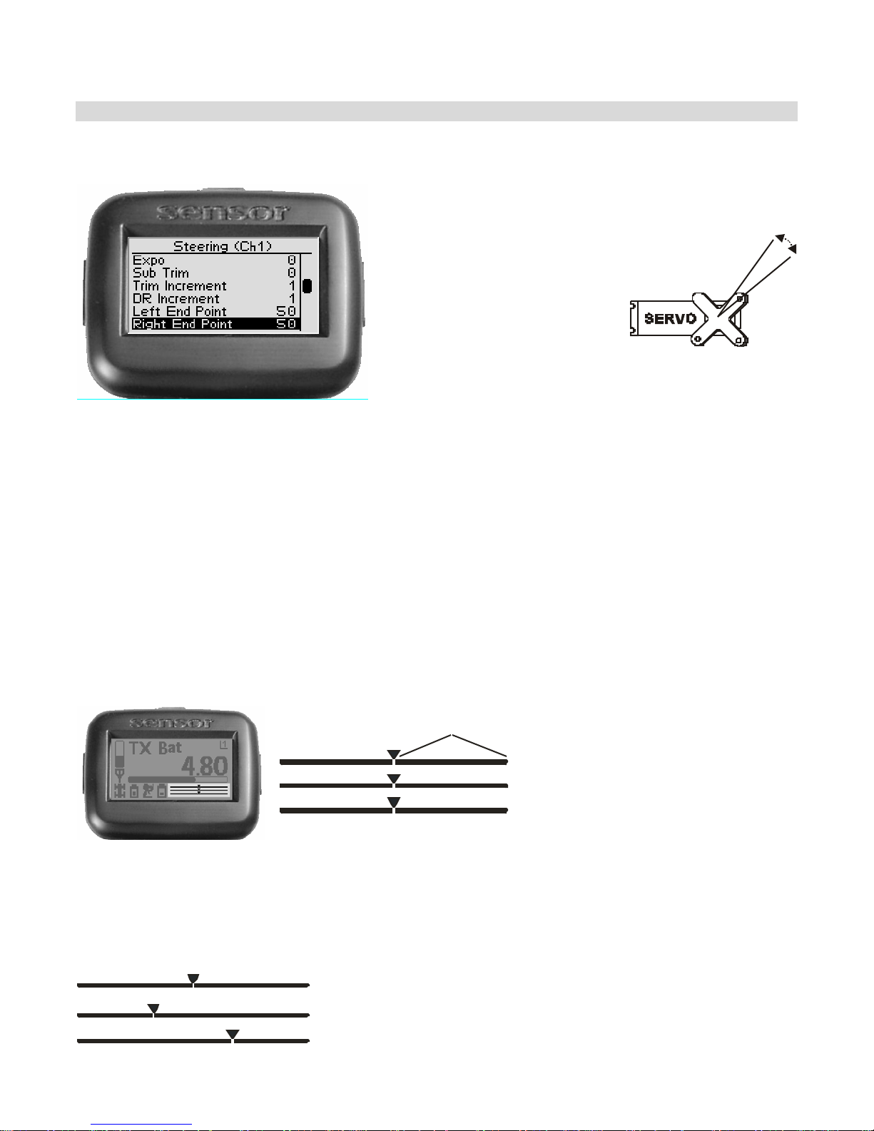
Steering Right End Po int
The steering right end point
value adjusts how far t he
steering servo turns to the
RIGHT with respect to its full
range of motion to the right.
End point adjustment should
be adjusted prio r to other
st eering sett ings, as the right
end point value affects other
steering set tin gs.
The right end point is set
independently of the left end
p oin t (wh ich adjusts how far
the stee ring s e r vo tu rns to the
LEFT).
The right e nd point settin g should be us e d to do the followin g:
• Limit steering th row to reduce mech anic al b in din g or servo strain t hat m ay occu r on full
s e rvo th ro w to t h e r ig h t. F or ex am p le, if the s e rvo is tr y in g to tu rn the st ee ri n g s y st em
to the right far ther than it is mechanically a b le.
• Ad just ste e r ing th r ow to c hange st e ering c h a ra cteris tics when tu rnin g to the r igh t.
For example, if your car is oversteering when turning to the right, then reduce t he Right
End Poin t value to reduce the range of the steering servo on the right.
On the driving screen, the
right e nd point is
represented by the length of
the bar to the right of the
Right End Poin t
S teeri ng (Ch1)
Throttle (Ch2)
Sh i f t (C h3)
poin ter on the upper bar.
The greater the right length
of the bar, the greater the
ri ght end poi nt va lue .
The position of the
pointer on the bar is
affected by the end point
value s (left and right)
and tri m setting.
Changing t he right end point value has the following visual effect on the driving scree n bars.
R ight end point value is approximately the same as the left en d point
value.
Increased right end point value (more servo travel to right is possible).
Decreased right e nd point value (less se r vo t r avel to right is possible ).
26
Page 30
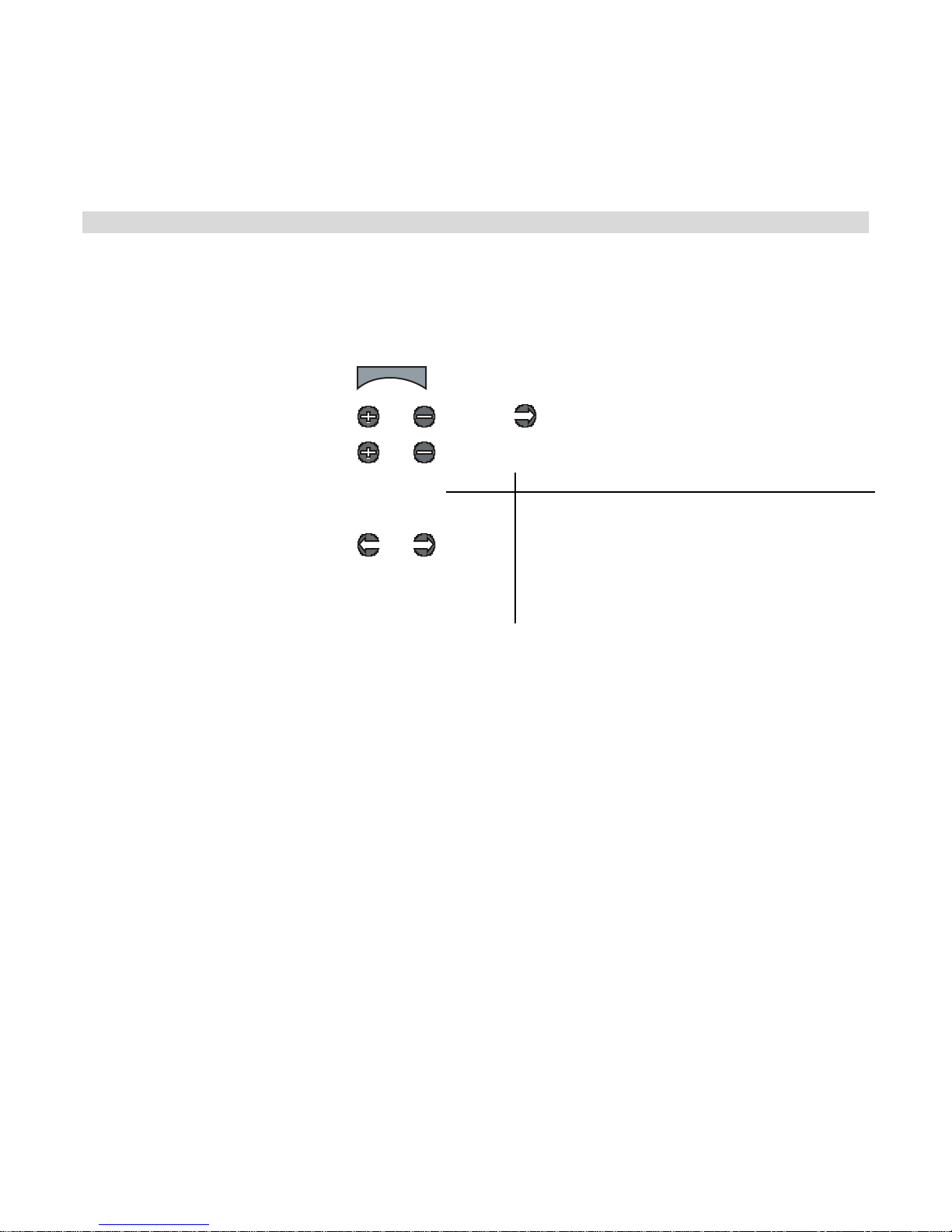
Th e po s iti on of th e p oin t er on t he ba r i s af fect ed by the steer ing end p oint val ues (lef t
and right) and trim setting; increasing t he right end po int value may visually appear to
have the same effect as decreasing the left end point value.
Ad justing th e Rig ht E nd Point
The right end point value is a relative value, and is expressed as the percentage of full t ravel
to the right. For example, setting the right end point value to “50” allows the steering servo to
turn only 50% of full travel to the right.
Use the navigation controls to adjust the right end point as follows:
1. Access the top function menu
from the driving screen.
2. Navigate to the Steering (Ch1)
menu.
3. Navigate to Right End Point.
4. Change the value.
menu
or : then
or
or
Value Description
0
1-99
100
Minimum right end point; allows NO turning
motion to the right.
Right end point setting is set to a percentage of
full right-turning range. For example , a val ue of
“50” gives 50% of f u ll right-turning range.
Maximum right end point; a llows F ULL right-
t urning range.
Tri m and EPA In te ract ion
A trim (or sub-trim) setting of 100 is equivalent to an End Point setting of 20.
27
Page 31
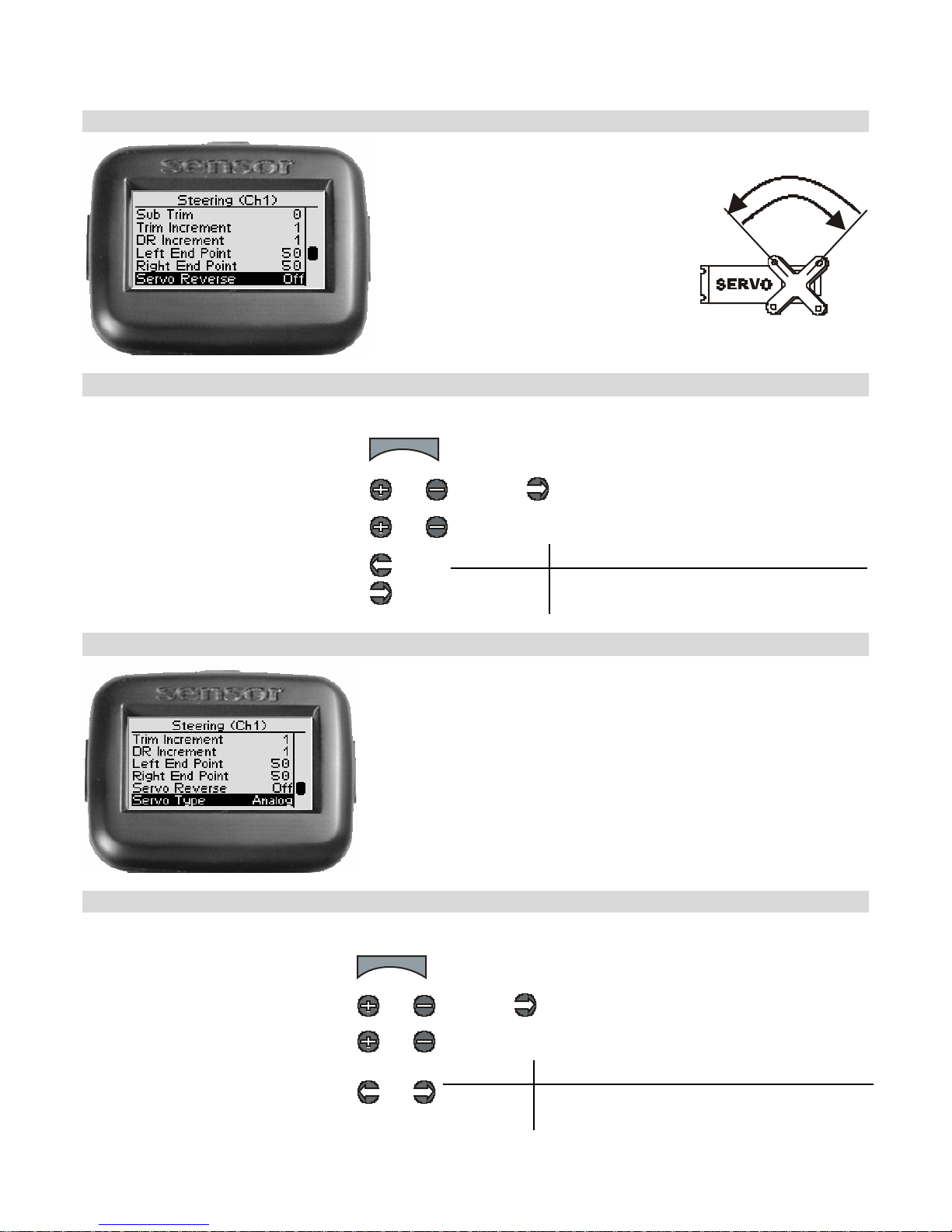
Steering Servo Rev erse
Steerin g serv o reversin g reve rses
the direction the servo moves upon
rec eiving an input from the st eering
wheel.
Chan g ing th e St eering S ervo R everse S ett ing
Use the navigation controls to ch ange t he st eering servo reverse setting as f ollows:
1. Access the top function menu from
the driving screen.
2. Navigate to the Steering (Ch1)
menu.
3. Navigate to Servo Reverse.
4. Change the value.
menu
or : then
or
or
Value Description
Off Standard servo direction.
On Reve rsed servo dire ction.
Steering Servo Type
Steering servo type lets you select the type of steering
servo (analog or digital) in the vehicle . Analog servos are
sent sign als at 50 frames/sec, w hile D ig ital se rv os are sent
sign als at 100 frames/sec.
If you have high end analog servos, they may operate
better wit h t he digital sett ing, t ry both settings and choo se
the best perform a nce.
Cha n ging the Steering Ser vo T ype
Use the navigation controls to change the steering servo type as follows:
1. Access the top function menu
from the driving screen.
2. Navigate to the Steering (Ch1)
menu.
3. Navigate to Servo Ty pe.
4. Change the value.
menu
or : then
or
or
Value Description
Analog Steering servo is analog.
Digita l Ste ering servo is digital.
28
Page 32
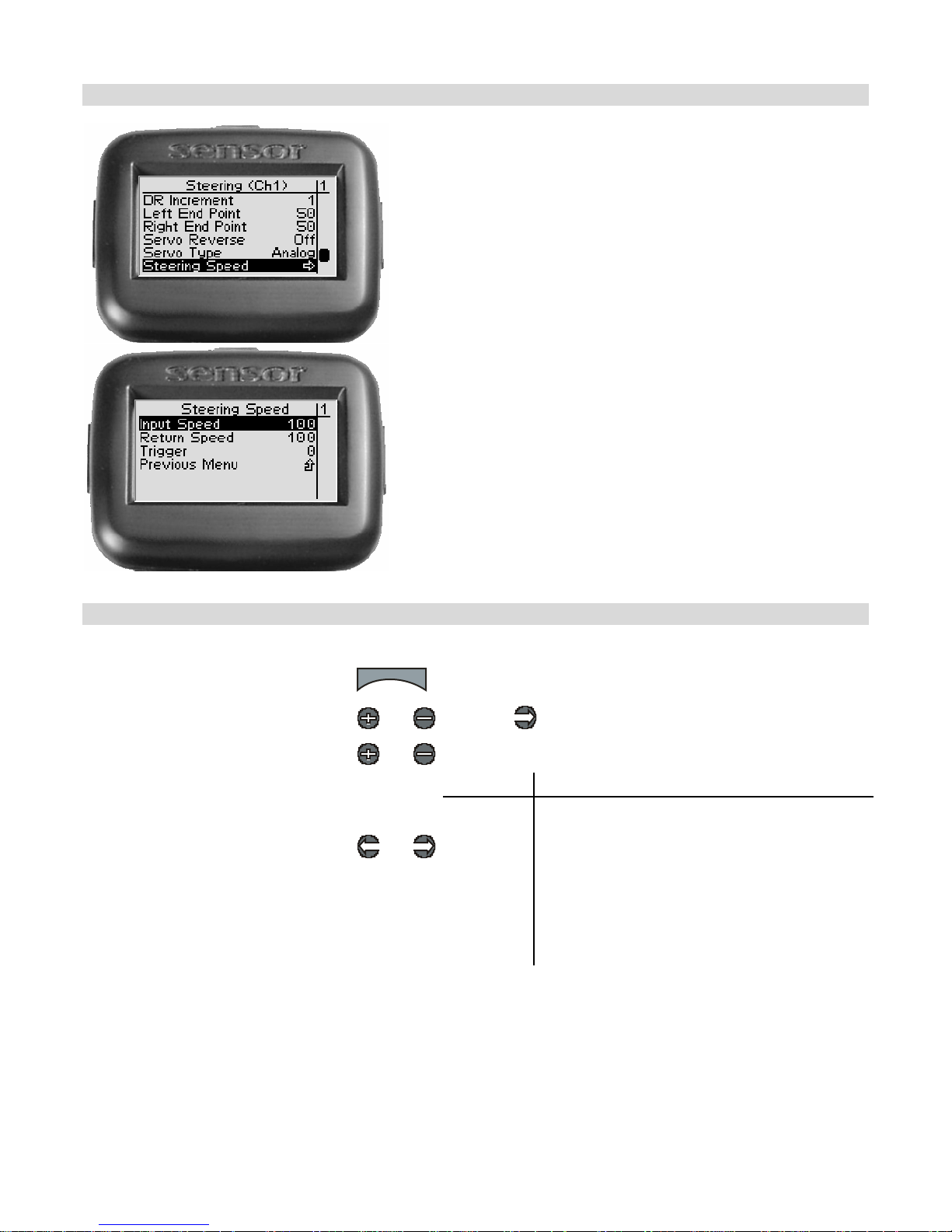
Steering Sp eed
Steering speed allows yo u to limit the maximum speed
that the steering servo will be driven to match your
m ov ements o n th e w heel . Th er e are thr e e p a r amet ers
t hat can be adjusted to precisely set up your limiting.
Trigger sets th e minimum amount o f contro l input
before the speed limit e r becomes ac tive. At 0%,
limiting is always active (input is always >= 0%). At
50%, limitin g is only active if the w heel is tu r ned half
wa y or m o re .
Input speed determines the limited speed that is
ap plied t o motions aw ay f rom center that are abov e t he
trigger setting . 100 is maximum se rvo mo v ement rate .
1 is minimum rate . De f au lt is 100 (full sp eed)
Return spe ed determines the lim ited s peed t hat is
applied to motions back toward center that are above
the trigger sett ing. 100 is maximum se rvo mo v ement
rate. 1 is minimum rate . Default is 100 (full speed)
Changing the Steering Speed
Use the navigation controls to change the steering servo type as follows:
1. Access the top function menu
from the driving screen.
2. Navigate to the Steering (Ch1)
menu.
3. Navigate to Steering Speed.
4. Change the values.
menu
or : then
or
or
Value Description
Input
Speed
Return
Speed
Trigger
The percentage of full speed appl ied to serv o
motion away from center once the trigger
amount has been exceeded.
The percentage of full speed appl ied to serv o
motion toward center once the trigger amount
has been exceeded.
The threshold above whi ch speed limiting will
be applied.
Interaction with other parameters
Servo Speed is applied after Expo. The trigger le vel for Servo Speed refe rs to the curved input
value.
29
Page 33
A
Throttle Functions
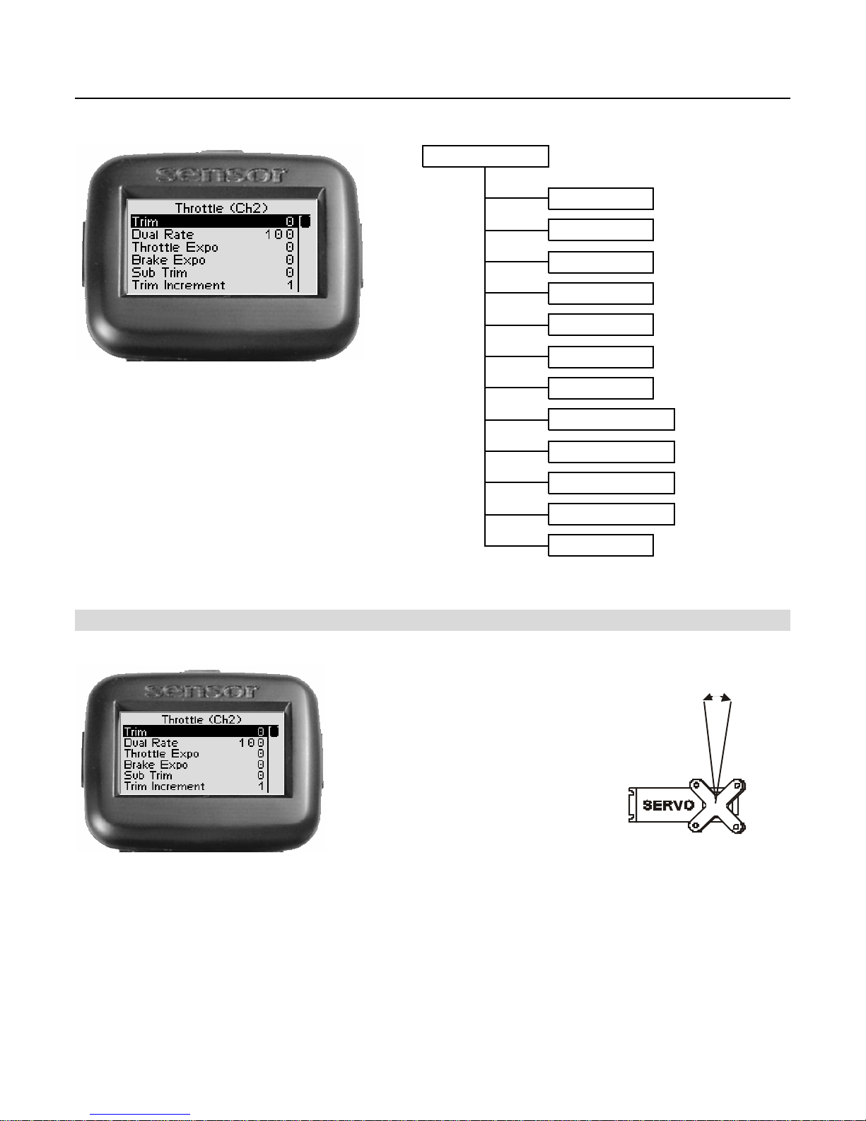
The following illus tration shows the function me nu str ucture fo r th e thro ttle functio ns :
Throttle ( Ch 2 )
Tri m
- 100 to 100
Thr ot tle Trim
Dual Ra te
Throttle Expo
Brake Expo
Sub Trim
Trim Increment 1 -
DR Increment
Brake End Point
Thro ttle End Point
Servo Reverse
S ervo Ty pe
Servo Speed Thr/Brake Speed,Trigger
0 -
- 100 to 100
- 100 to 100
- 100 to 100
1 -
100
20
20
0 to 100
0 to 100
Off , On
nalog , Dig ital
,
Throt tle tr im adjusts the restin g
(centered) position of the throttle
serv o horn (electric or nitro
vehicle) or the neutral point of an
ESC (e lectric vehicle).
When in itially settin g up the
vehicl e, the throttle tri m setting
should be set to 0. On a thro ttle
serv o, the serv o horn shou ld be
posit ioned as appropriate on the
serv o.
30
Page 34
Throttle Trim
S teering (Ch1)
Throttle (Ch2)
Shift (Ch3)
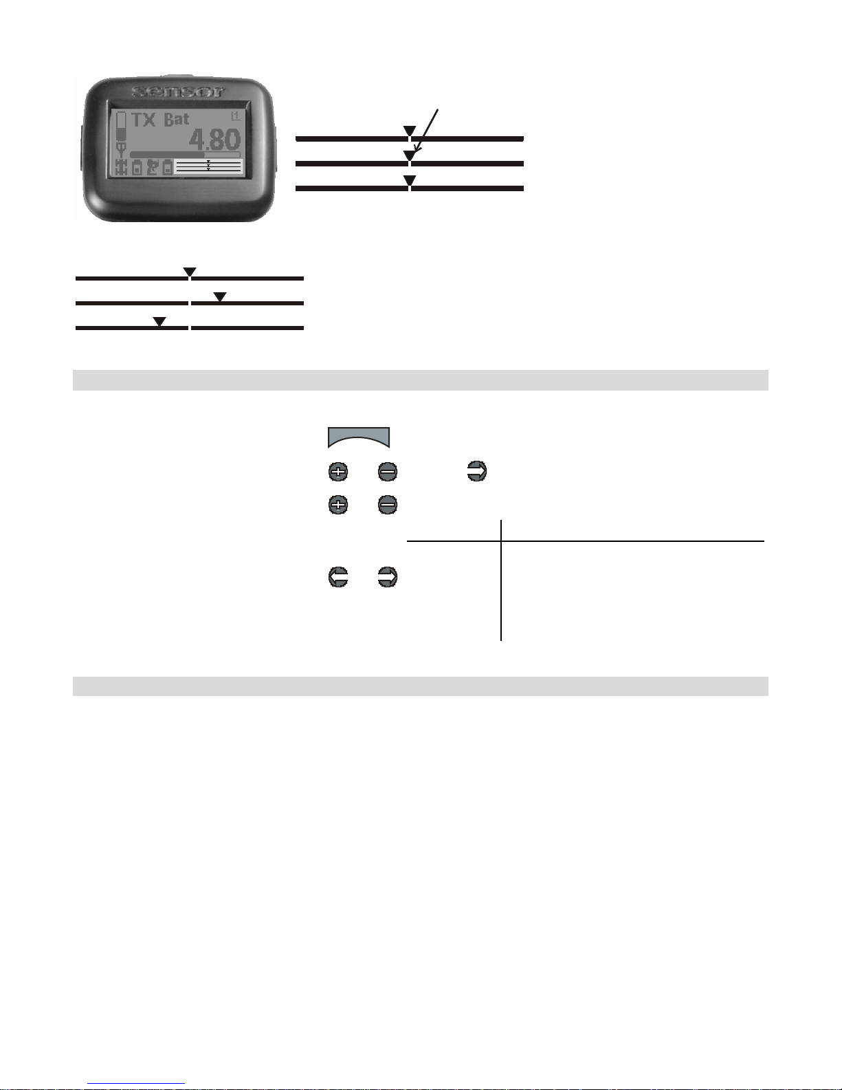
On the dri ving screen,
throttle trim is
represented by the
position of the pointer
on t h e middle bar.
Cha nging the thro ttle trim ha s the followin g visual effect on the driving screen bar s :
Throttle trim is centered in range (value = 0)
Throttle trim is offset to throttle end (+ve value)
Throttle trim is offset to brake end (-ve value)
Ad j ust ing Thro t tle Tr im using the Function M e nu
U se the na viga tion controls to a djust thr o ttle trim a s follows:
1. Access the top function menu from
the driving screen.
2. Navigate to the Thr ottle (C h2)
menu.
3. Navigate to Trim.
4. Change the value.
menu
or : then
or
or
-ve value
(-100 Æ -1)
+ve value
(1 Æ 100)
Value Description
0 Throttle trim is centered within servo
range.
Throttle trim is to the BRAKE end.
Throttle trim is to the THROTTLE end.
Ad j ust ing Thro t tle Tr im using the T r im B utton
Y ou c an a ls o use the T3 trim but ton to adju s t thro ttle tr im.
Tri m and EPA In te ract ion
A trim (or sub-trim) setting of 100 is equivalent to an End Point setting of 20.
31
Page 35
Thr ot tle D u al R at e
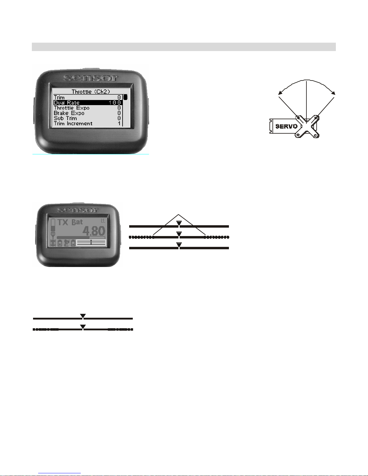
Thrott le dual rate adjust s the
range of serv o movement whe n
the throttle trigger is move d from
full br ake to f ull th r o ttle positio n.
This is us ed to increas e o r
de c r ea se th e t hr ot tl e s e n s iti v ity
ac ross the entire servo range.
The throttle dual rate value is
applied to both thrott le and brake
end, and is e xpressed as a
p ercentage of servo range
(configured by e nd point
adjustments).
On the dri ving screen,
throttle dual rate
range is represented
Dual Rate Range
S teering (Ch1)
Throttle (Ch2)
Shift (Ch3)
by the solid length of
the middle bar.
The total length of
the bar (sol id and
dotted) represents
the servo range. The
length of the solid bar
represents the servo
range set by the dual
rate value .
Cha nging the dua l r ate s etting ha s the following vis ua l effec t on the d r iving scr een bars :
Full servo range is used.
Lowe r dual ra te value reduces servo range.
32
Page 36
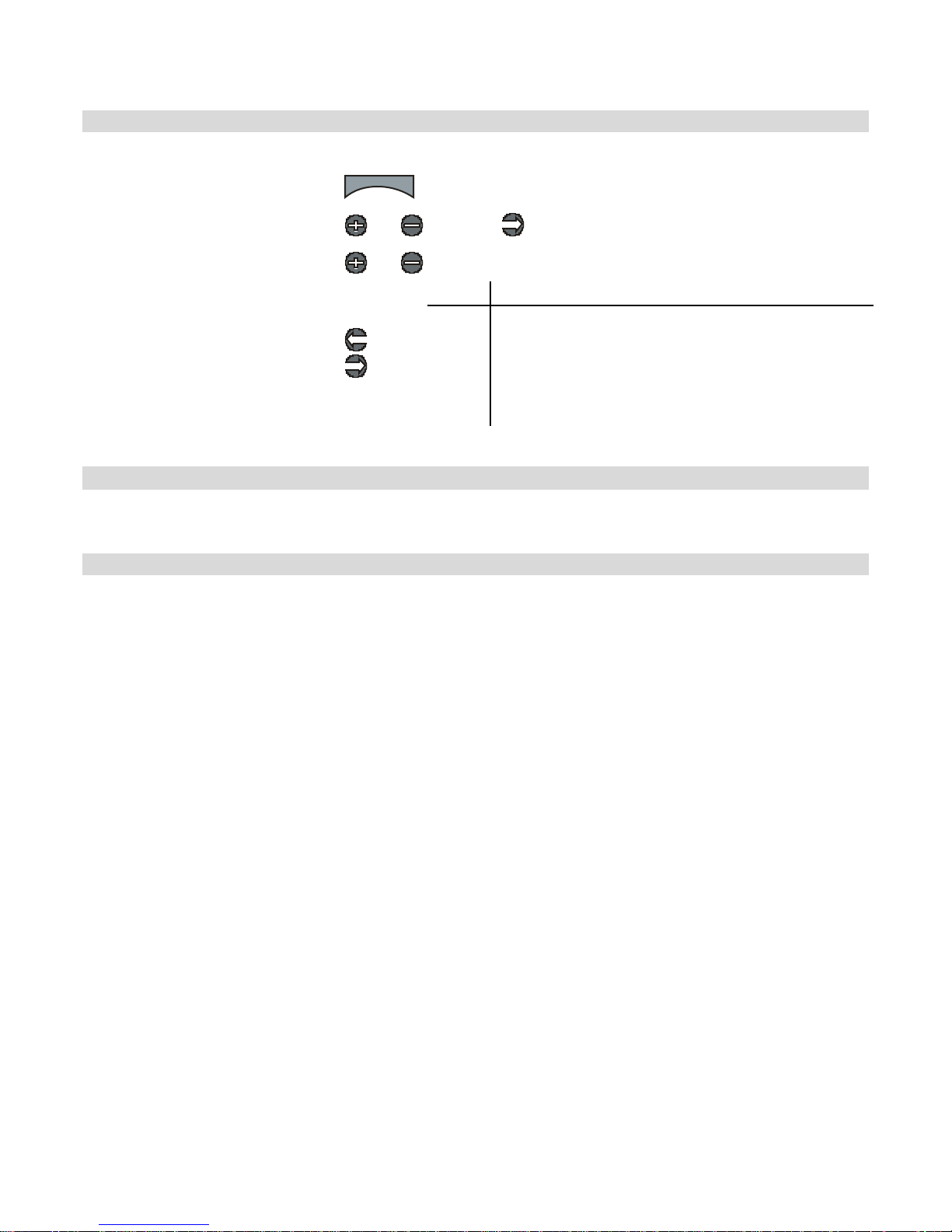
Adj usting Thro t tle D ua l Rate using the Fu nctio n Me nu
Use the navigation controls to adjust throttle dual rate as follows:
1. Access the top function menu
from the driving screen.
2. Navigate to the Thr ottle (C h2)
menu.
3. Navigate to Dual Rate.
4. Change the value.
menu
or : then
or
or
Value Description
0 Throttle/brake range is set to minimum (0%).
Throttle/brake range is set to a percentage of full
1-99
100 Throttle/brake range is set to full (100%)
range.
For example, value “50” gives 50% of full servo
range.
Ad j ust ing Thro t tle Dua l R ate us ing the Tr im B utton
Y ou c an a ls o use the T1 trim but ton to adju s t thro ttle d u al r a te .
Dual Rate and End Point Adjust ment
Full servo range is dete rmined by the thrott le and brake end point adjustment s. The dual rate
value determines the relat ive servo range between the throttle and brake end points. The
ser vo will never move beyond the s et end point adjustments, no m at ter what dual ra te se ttin g
is applied.
33
Page 37
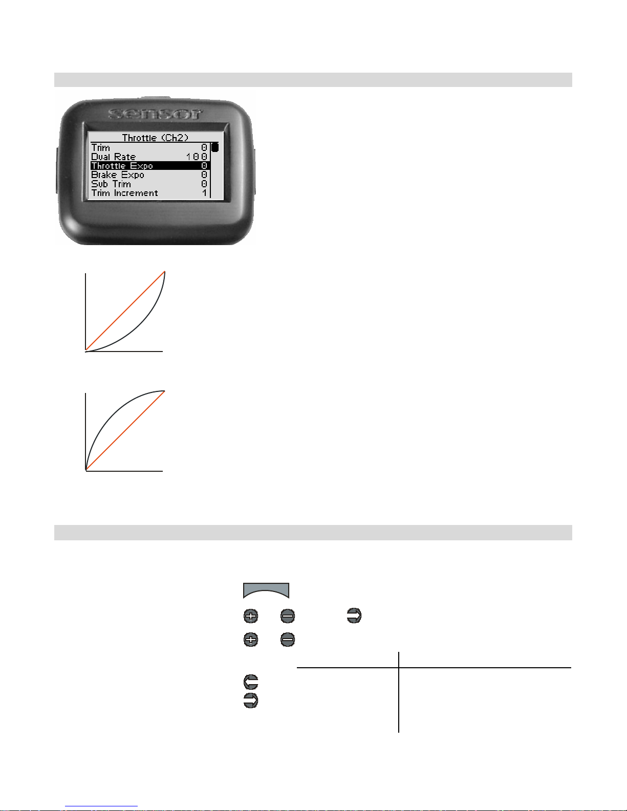
Thr ot tle Ex ponential
Servo travel
THROTTLE
Thro ttle expo nential a djusts how quickly or slowly the
throttle servo responds with respect to the amount that
the t h ro ttle tr igg er i s mo v ed to th e THR OT TL E e nd.
This af fects the sensitivity of t he throttle servo near its
neut ral position.
Adjusting the th rot tle exponential does no t affec t the
brake exponential; these sett ings are set individually.
0% ( line ar)
-1 ~ -100%
(mi ld)
A neg ative (-ve ) exponential va lue g ives a milde r th rott le
response near t he t hrottle neu tral p oint, m ak in g it L ESS
r e spo n s ive to bra king inp uts at th e throt tle trigg er.
Neutral
-ve exp one nti al
(mi lder resp onse)
Servo travel
THROTTLE
1~100%
(quick)
Ful l thro ttl e
A positive (+ve ) e xp onential v alue gives a quicker thr o ttle
0% (linear)
response near t he t hrottle neu tral p oint, m ak in g it MORE
r e spo n s ive to bra king inp uts at th e throt tle trigg er.
Neutral
+ve exp one nti al
(quicker r esponse)
Ful l thro ttl e
Adj usting Thro t tle Ex po nential
U se the naviga tion controls to adj ust thr ottle e xponential a s follows:
1. Access the top function menu from
the driving screen.
2. Navigate to the Thr ottle (C h2)
menu.
3. Navigate to Throttle Expo.
4. Change the value.
menu
or : then
or
Value Description
0 Ne utral t hrottle response (l inea r).
or
-ve value
(-1 to -100)
+ve value
(1 to 100)
Milder throttle response near
neutral.
Quicker throttle response near
neutral.
34
Page 38
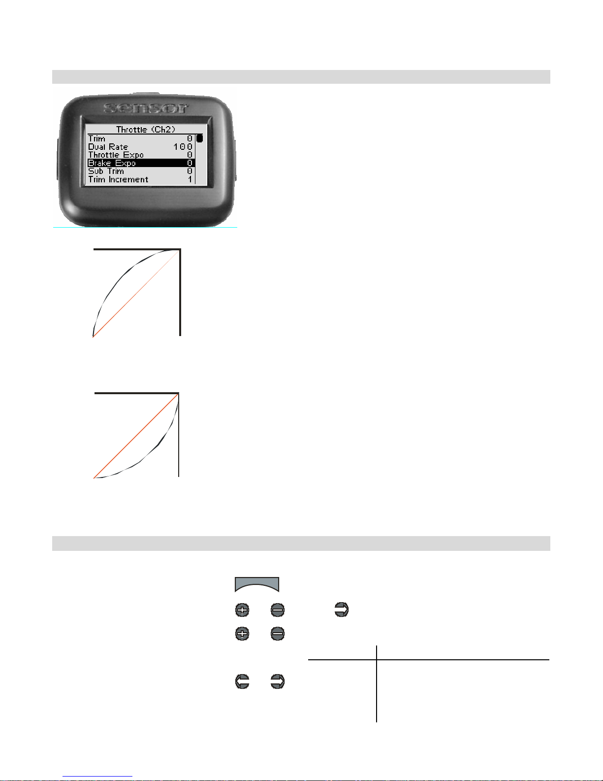
Brake Exponential
Ful l br ake
-1 ~ -100%
(mild )
0% (l i n ear )
Neutral
Servo travel
BRAKE
Bra ke exponential adjus ts how quickly or slowly the
throttle servo responds with respect to the amount that
the t h ro ttle tr igg er i s mo v ed to th e BRAKE e n d . This
affects the sensitivity of the thr o ttle servo nea r its neutral
posit ion.
Adj u sti n g the br a k e ex pone nti a l does not af f e c t the
thro ttle expo nential; these settings ar e s et in dividua lly.
A negative ( - ve) expo nential value gives a milder br a king
response near t he t hrottle neu tral p oint, m ak in g it L ESS
r e spo n s ive to bra king inp uts at th e throt tle trigg er.
-ve expon ential
(milder respo ns e)
Fu ll br ake
0% ( li near)
+ve ex ponentia l
(qu icker response)
1~100%
( quic k)
Ser vo t ra vel
BRA KE
Neutral
A positive (+ve ) e xp onential v alue gives a quicker br a king
response near t he t hrottle neu tral p oint, m ak in g it MORE
r e spo n s ive to bra king inp uts at th e throt tle trigg er.
Adj usting Br a k e E xpone ntial
U se the naviga tion controls to adjust brake e xponentia l as follows:
1. Access the top function menu from
the driving screen.
2. Navigate to the Thr ottle (C h2)
menu.
3. Navigate to Brake Expo.
4. Change the value.
menu
or : then
or
Value Description
or
-ve value
(-1 to -100)
+ve value
(1 to 100)
0 Neutral braking response (linear).
Milder braking response near neutral.
Quicker braking response near
neutral.
35
Page 39
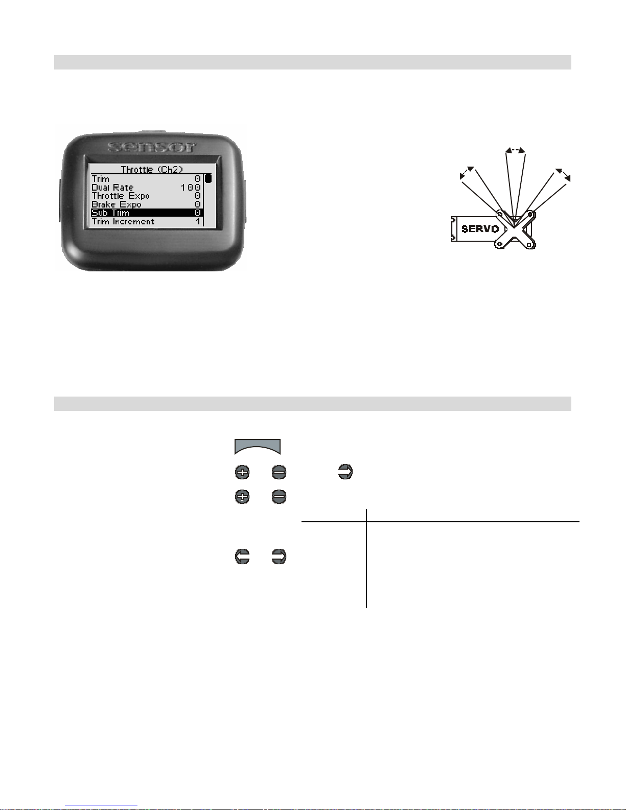
Throttle Sub-Trim
If you find that you have to use a large amount of throttle sub-trim to adjust the
throttle position, you should consider resetting the steering sub-trim to 0 and re-
ad justing the servo ho rn on the servo output shaft .
Throt tle su b-trim ad justs the
center point of the throttle servo.
This differs from throt tle trim in
that throttle sub-t rim adjusts t he
servo’s entire travel range; by
moving t he center point of the
s er v o, th e t h r ottle an d br a k e end
points (throttle, brake) stay the
sa me rela tive “distance” from t he
serv o center.
Thro ttle sub-trim should be
initially adjusted be fore using
thro ttle tr im, wh ic h is us ed t o
make f ine ad justment s to center
the t h ro ttle within t h e to tal
steering range.
Ad j ust ing Thro t tle Su b-tr im
U se the na viga tion controls to adj ust thr o ttle sub-trim as follows:
1. Access the top function menu
from the driving screen.
2. Navigate to the Thr ottle (C h2)
menu.
3. Navigate to Sub Tri m.
4. Change the value.
menu
or : then
or
or
Value Description
0 Throttle sub-trim is centered within the
-ve value
(-100 Æ -
1)
+ve value
(1 Æ 100)
s ervo range .
Throttle sub-trim is to the BRAKE end.
Throttle sub-trim is to the THROTTLE end.
Tri m and EPA In te ract ion
A trim (or sub-trim) setting of 100 is equivalent to an End Point setting of 20.
36
Page 40
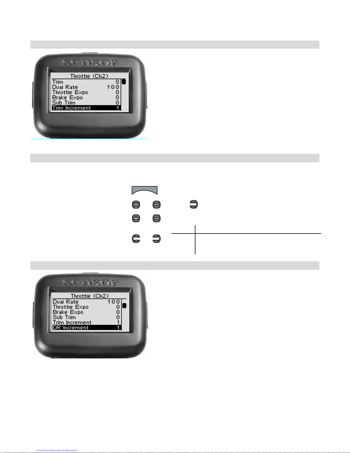
Thr ot tle Trim Incremen t
Thro ttle tr im increment adj usts the se nsitivity of the
thrott le trim button, by adjusting the amou nt that the
thro ttle tr im value changes for o ne “step” of
adjustment.
For example, sett ing the t hrottle trim increment value
to “5” changes the throttle trim value by 5 each time
that the throttle tri m button is pressed once.
Ad j ust ing Thro t tle Tr im Inc r ement
Use the navigation controls to adjust throttle trim increment as follows:
1. Access the top function menu from
the driving screen.
2. Navigate to the Thr ottle (C h2)
menu.
3. Navigate to Trim Increment.
4. Change the value.
menu
or : then
or
or
Value Description
1-20
Throttle trim value changes by set increment.
Use smaller values for finer trim control.
Use larger values for coarser trim control.
Thro ttle Dual Rate In crement
Thro ttle dua l ra te increment adjusts the s ensitivity of
the thrott le dual rate b y adjusting the amou nt thrott le
dual rate value increments for one “step” of
adjustment.
For example, sett ing the t hrottle dual rate increment
value to “5” change s the thrott le dual rate value b y 5
each time that the throttle dual rate trim button is
pr ess ed on ce .
37
Page 41
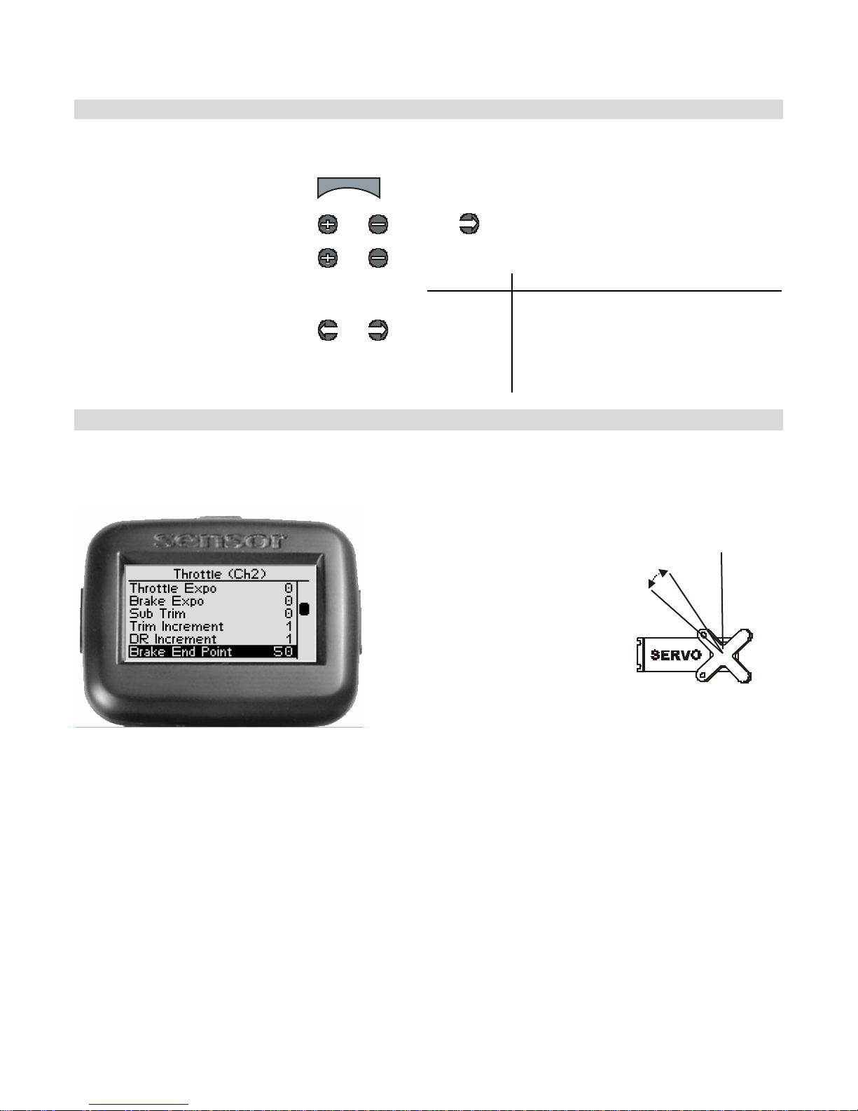
Ad j ust ing Thro t tle Dua l R ate In c r e me nt
Use the navigation controls to adjust throttle dual rate increment as follows:
1. Access the top function menu
from the driving screen.
2. Navigate to the Thr ottle (C h2)
menu
3. Navigate to DR Increment.
4. Change the value.
menu
or : then
or
or
Value Description
1-20
Throttle dual rate value changes by set
increment.
Use smal ler value s for f iner dua l rate
control.
Use large r values f or coarser dual rate
control.
Brake End P oint
Th e bra k e end poin t va lue
ad justs how far t he t hrot tle
goes to the BRAKE en d wi th
respect to its full range of
moti on to the bra ke en d. End
p oin t adjustment sho uld be
adjusted prior to other
throttle settings, as the brake
end point value affects other
thrott le sett ings.
The brake end point is set
ind e pen dently o f the thro ttle
end point (which adjusts how
f a r the throt tle mo ves to t h e
THROTTLE end).
The brake end point setting should be used to do the following:
• Limit throttle throw to reduce me chanic al b inding or serv o strain that m ay occu r on f ull
servo throw t o the brak e end . For example, if the servo is trying to pu ll a me ch anic al
br ake linka ge far ther tha n it is mechanically ab le.
• Adjust braking range to reduce the full braking force of t he vehicle.
38
Page 42
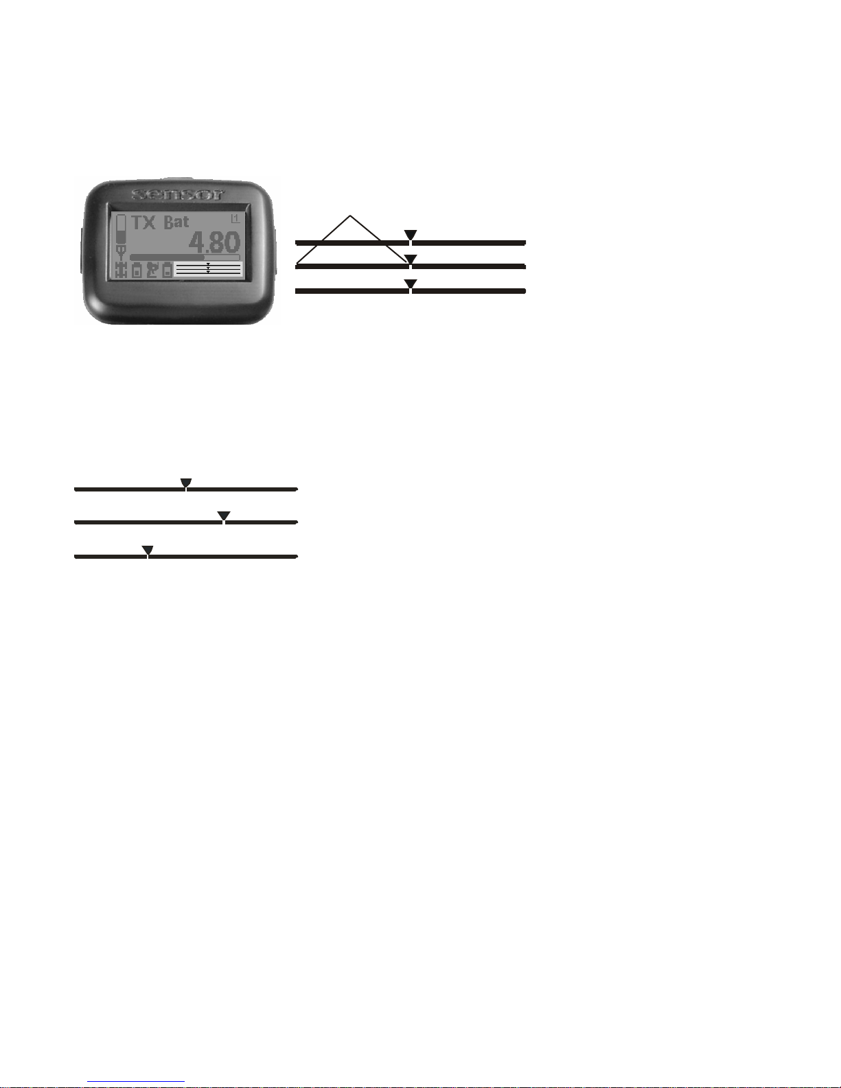
On the dri ving screen,
the brake end point is
represented by the
length of the bar to
the left of the pointer
on t h e middle bar.
Brake End Point
S teering (Ch1)
Throttle (Ch2)
Shift (Ch3)
The greater the left
length of the bar, the
greater the brake end
point value.
The position of the
pointer on the bar
is affected by end
point settings
(throttl e and
brake) and trim
setting.
Changing t he brake end point value has the following visual effect on the driving screen bars.
Brake end poi nt value is approximately the same as the throttle end
point value.
Increased brake end poi nt value (more servo travel for BR AKING is
possible).
Decreased brake end point value (less servo travel for BRAKING is
possible).
The position of the pointer on the bar is affected by end point settings (throttle and
brake) and trim setting; increasing the brake end point value may visually appear to
ha v e the same ef fe c t a s de cr easing th e throt tl e en d p oin t val u e.
39
Page 43
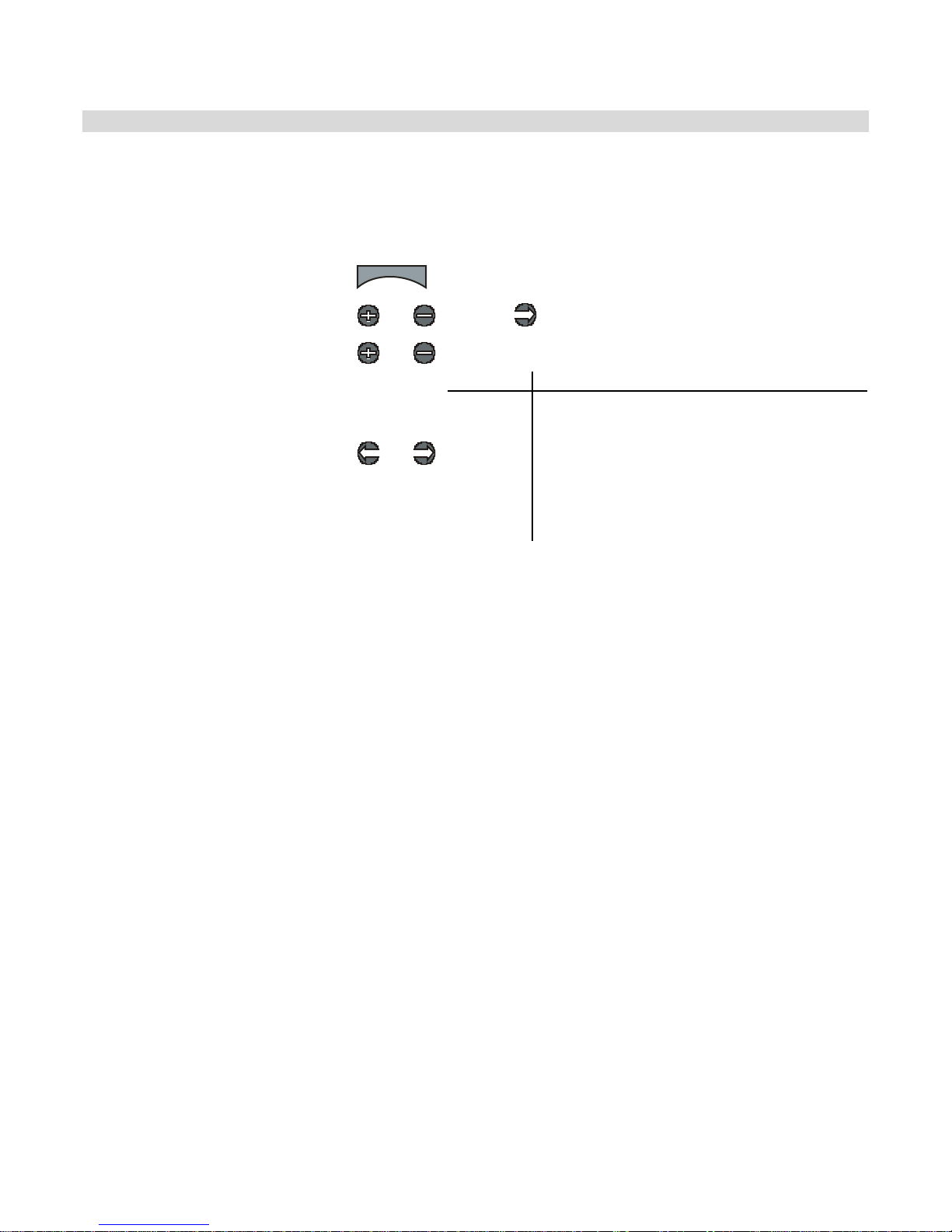
A d ju sting th e Brake End Po int
The brake end point value is a relative value, and is expressed as the percentage of full t ravel
to the BRAKE end. For example, setting the brake end point value to “50” allows the throttle to
go t o o nly 50% of full br ake.
Use t he navigation controls to adjust the brake end point as follows:
1. Access the top function menu
from the driving screen.
2. Navigate to the Thr ottle (C h2)
menu.
3. Navigate to Brake End Point.
4. Change the value.
menu
or : then
or
or
Value Description
0
1-99
100
Minimum brake end point; al lows NO brake
travel.
Brake end poi nt value is set to a percentage
of full braking travel.
For example, a value of “50” gives 50% full
brake travel.
Maximum brake end point; all ows FUL L brake
travel.
Tri m and EPA In te ract ion
A trim (or sub-trim) setting of 100 is equivalent to an End Point setting of 20.
40
Page 44
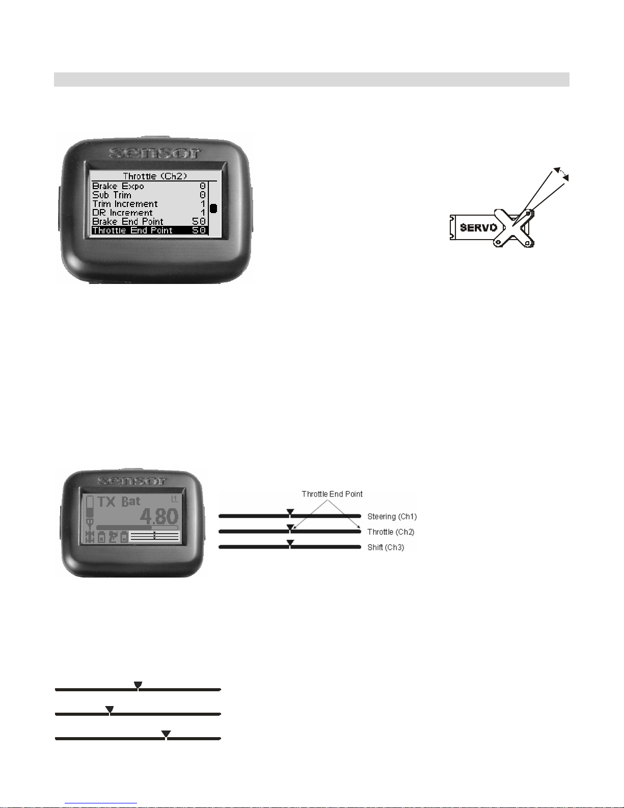
Thr ot tle End Po int
Th e t hro t tl e en d p oin t val u e
ad justs how far t he t hrot tle
goes to the THR OT TL E end with
respect to its full range of
m o tion to t h e th rottle end. E n d
p oin t adjustment sho uld be
adjusted prior to other throttle
setti ngs, as the throttle end
point value affects other
thrott le sett ings.
The thro ttle end poin t is set
independently of the brake end
p oin t (wh ich adjusts how far
the throttle servo turns to the
BRAKE en d).
The throttle end point setting should be used to do the following:
• Limit throttle throw to reduce me chanic al b inding or serv o strain that m ay occu r on f ull
serv o t hrow t o th e t hrottle end. For exam ple, if the serv o is trying to pu ll a me ch anic al
thro ttle linkage fa rther tha n it is mec hanically a ble.
• Ad just throttle r ang e to reduc e the to p s pee d o f the vehicle.
On the driving screen, the
throttle end point is
represented by the length of
the bar to the right of the
poin ter on the middle ba r .
The greater the right length of
the bar, the greater the
throttle end point value.
The position of the pointer
on the bar i s aff ected by
end point values (throttle
and brake) and trim
setting.
Changing the thrott le end point value has the following visual effect on the driving screen
bars.
Throttle end point value is approximately the same as the brake end
point value.
Increased throttle end point value (more servo travel for THROTTLE is
possible).
Decreased throttle end point value (less servo travel for THROTTLE is
possible).
41
Page 45
Th e po s iti on of th e p oin t er on t he ba r i s af fect ed by en d point va lues ( thr ot tl e a nd
br ake) a nd tr im settin g; increasing the throttle end point va lue ma y v isually appear to
have the same effect as decreasing the brake end point value.
Ad j usting the T hrottle E nd Point
The throttle end point value is a r elative v alue, a nd is expres sed as the percentage of full
tr a v el to the THROTTLE en d . F or ex a m p le, se t ti n g the thro t tle en d po in t va lue t o “ 50 ” allows
the t h ro ttle to go to on ly 50% o f full tr av el to the throttle end.
Use the navigation controls to adjust the throttle end point as follows:
1. Access the top function menu from
the driving screen.
2. Navigate to the Thr ottle (C h2)
menu.
3. Navigate to Throttle End Point.
4. Change the value.
menu
or : then
or
or
Value Description
0 Minimum throttle end point; allows NO throttle.
1-99
100
Throttle end point value is set to a percentage
of full throttle travel.
For example, a value of “50” gives 50% full
throttle travel.
Maximum throttle end point; allows FULL
throttle travel.
Tri m and EPA In te ract ion
A trim (or sub-trim) setting of 100 is equivalent to an End Point setting of 20.
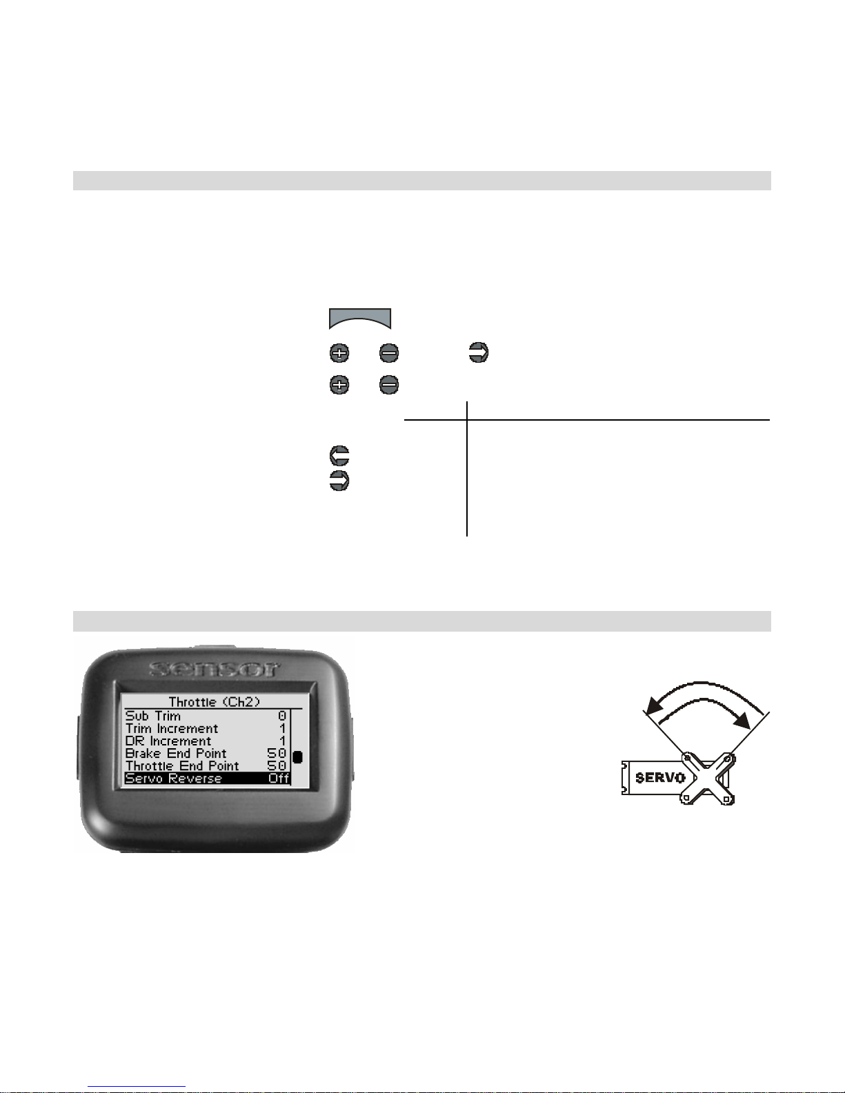
Throttle Servo Reverse
Throt tle serv o re versing
reverses the direction the
throt tle serv o moves u pon
rec eiving an input from the
th r ot tle trigg e r .
42
Page 46
Ch an g ing t he Th rottle Servo R ev erse S ett ing
U se the na viga tion controls to change the throttle ser vo reve rse settin g as follows :
1. Access the top function menu from
the driving screen.
2. Navigate to the Thr ottle (C h2)
menu.
3. Navigate to Servo Reverse.
4. Change the value.
menu
or : then
or
or
Value Description
Off Standard servo direction.
On Reve rsed servo dire ction.
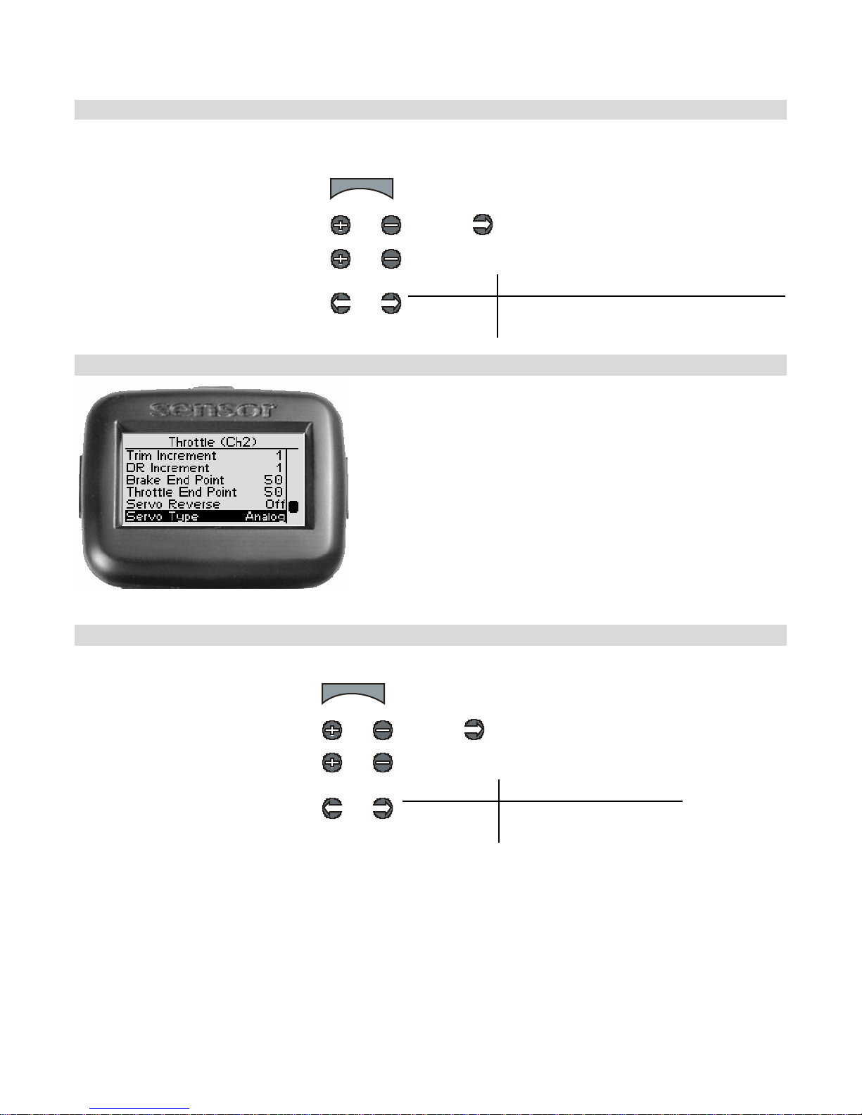
Throttle Servo Type
Th r ot tle s erv o typ e l ets yo u s e lect the ty pe o f th ro ttle
servo (analog or digital) in the vehicle . Analog servos
are sent signals at 5 0 f ram es/sec, while Dig ital se rvos
are sent signals at 1 00 frames/sec.
If you are running an electric car wit h an ESC, it may
perfor m be tt er wi th th e digital se tti ng. Some E SCs ma y
not operate at all wit h the higher frame rate. Try both
s ettings an d choose th e bes t perf or m ance .
Ch a n gin g t h e Th rottle Serv o Ty pe
Use the navigation controls to change the throttle servo type as follows:
1. Access the top function menu
from the driving screen.
2. Navigate to the Thr ottle (C h2)
menu.
3. Navigate to Servo Ty pe.
4. Change the value.
menu
or : then
or
or
Value Description
Analog Throttle servo is analog.
Digital Throttle servo is digital.
43
Page 47
Throttle Speed
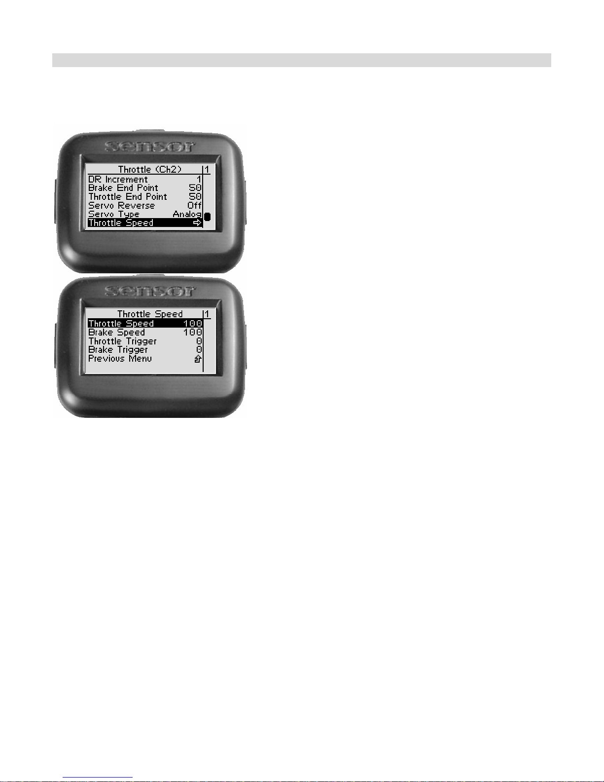
Th rottle speed allows yo u to limit the maximum speed
that the thrott le se rvo w ill be d riven to match your
movement s on the trigger. T here are four paramet ers
t hat can be adjusted to precisely set up your limiting.
Throttle Speed determines the percent age of full speed
th at is a p p lied to the throt tle movemen ts th at a re
above the thrott le trigge r setting. 100 is maximum
servo movement rate. 1 is min imum rate. Defau lt is
100 (full speed).
Brake Speed determines the percentage of full speed
that is ap plie d t o brakin g m oveme nts that are above
the trigger sett ing. 100 is maximum se rvo mo v ement
rate. 1 is minimum rate . Default is 100 (full speed).
Throttle Tri gger sets the mini mum amount of control
input before the speed limiter becomes active. At 0%,
limiting is always active (input is always >= 0%). At
50%, limitin g is only active if the thr o ttle is on half way
or more.
Brake Trigge r set s the minimum amou nt o f control
input before the speed limiter becomes active. At 0%,
limiting is always active (input is always >= 0%). At
50%, limitin g is only active if the br ake is on ha lf way
or more.
44
Page 48
Chan ging t h e Th rott le S p eed
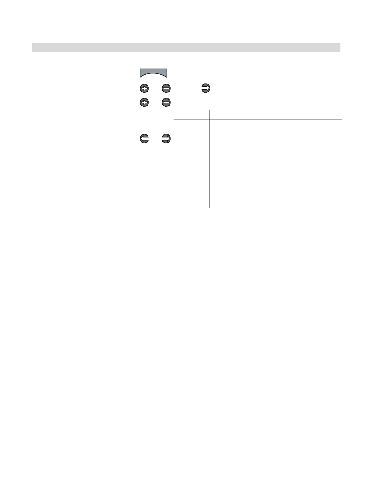
Use the navigation controls to change the steering servo type as follows:
1. Access the top function menu
from the driving screen.
2. Navigate to the Steering (Ch1)
menu.
3. Navigate to Throttle Speed.
4. Change the values.
menu
or : then
or
or
Value Description
Throttle
Speed
Brake
Speed
Throttle
Trigger
Brake
Trigger
The amount of limiting applied to servo
throttle motion once the trigger amount has
been exceeded.
The amount of limiting applied to servo brake
motion once the trigger amount has been
exceeded.
The percentage of full throttle range that will
be limited.
The percentage of full braking range that will
be limited.
I nter a c ti on wi t h o ther Se t tings
• Servo Speed is applied after Expo. The trigger levels refer to the curved input value.
• ABS is applied after Brake Speed, so Brake Speed can lim it how quickly the brake input
moves to the ABS Act ive region, but once there ABS pulses happen at full speed.
• Ser vo Sp eed is a pplied after Au toStart, so if the A u toStart Level is set higher than the
Thro ttle Speed Tr igger, the s ervo movement will be s lowed.
• Idle Up only takes effect when the trigger is centered. Throttle Speed can slow down
the return to center, and therefore slow down Idle Up activation. Once Idle Up is
started, the servo will j um p to the set p os ition.
45
Page 49
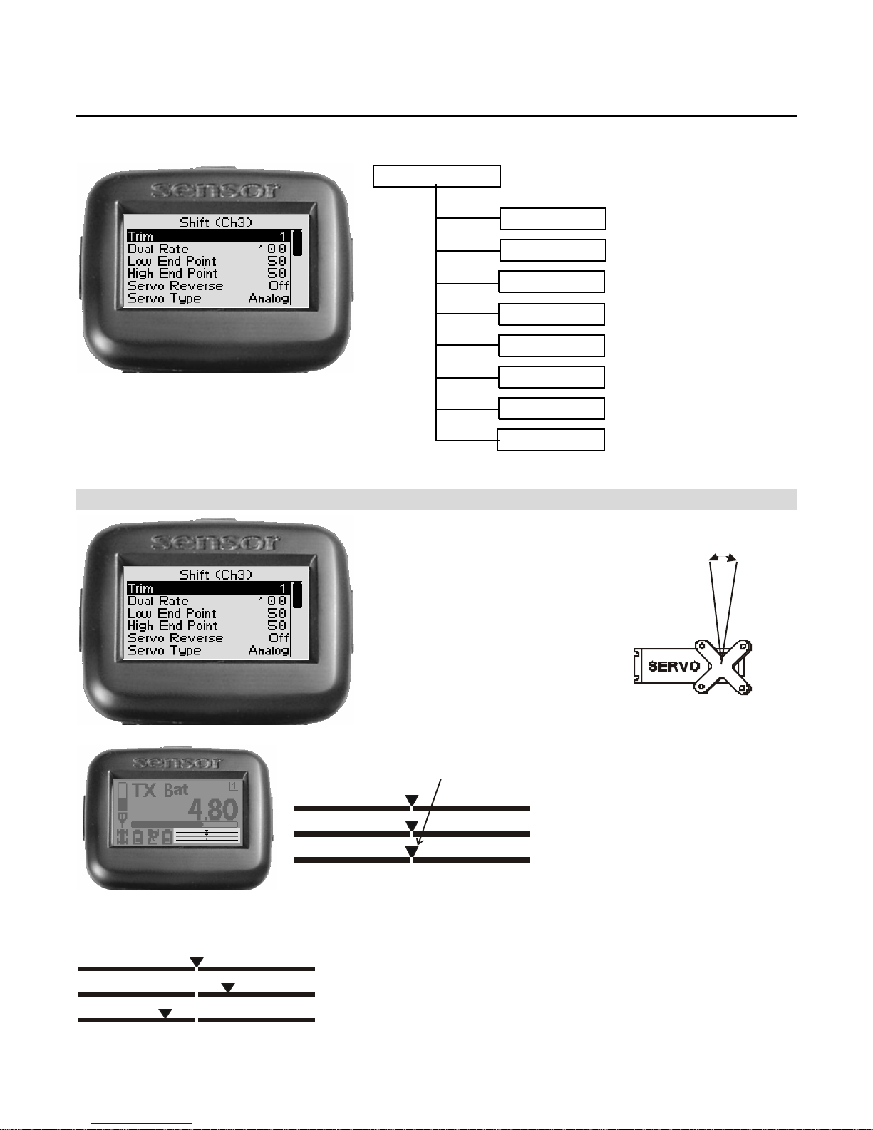
Shift Servo Functions
The following illus tration shows the function me nu str ucture fo r th e s hift ser vo functio ns:
Shift ( Ch 3 )
Trim
- 100 to
100
Shift Servo Trim
Dual Rate
Low End P oint
High End Point
Servo Reverse
S ervo Type
Mode
Ch3 Speed
Shift servo trim adjusts the
resting (centered) position of
the shift servo.
When in itially settin g up the
veh ic le, the shift servo t rim
set tin g should be set to 0. On
the shift servo, the servo horn
should be pos itioned as
appropriate on the servo.
0 -
100
- 100 to 0
0 to 100
Off , On
Analog , Digital
Off , Togg le , Hold , 4 WS
Thr/Brake Speed,Trigger
Ch angin g t he shift servo t rim has t he f ollowing visual effe ct on the drivin g screen bars:
Shift Servo T rim
S teering (Ch1)
Throttle (Ch2)
Shift (Ch3)
Shift servo trim is centered in range (value = 0)
Shift servo trim is offset to high end (+ve value)
Shift servo trim is offset to low end (-ve value)
46
On the dri ving screen,
shift servo trim is
represented by the
position of the pointer
on the bottom bar.
Page 50
Ad j ust ing Shift Se r vo Tr im
U se the na viga tio n controls to a djus t s hift servo tr im as follows:
1. Access the top function menu
from the driving screen.
2. Navigate to the Shi ft (Ch3)
me nu.
3. Navigate to Trim.
4. Change the value.
menu
or : then
or
or
-ve value
(-100 Æ -1)
+ve value
(1 Æ 100)
Value Description
0 Shift servo trim is centered within the
s ervo range .
Shift servo trim is to the LOW end.
Shift servo trim is to the HIGH end.
Tri m and EPA In te ract ion
A tr im (or sub-tr im) settin g of 100 is e quivalent to an End Point settin g of 20.
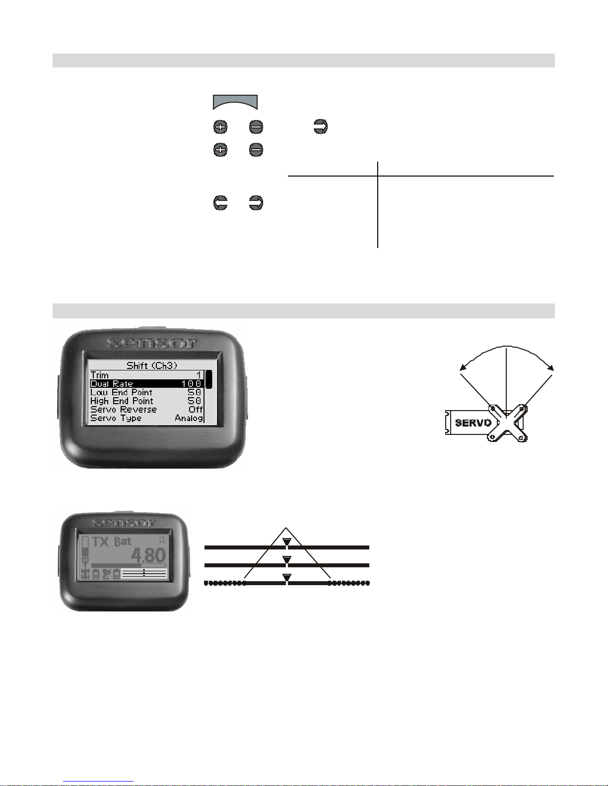
Shift Servo Dual Rate
Shift servo dual rate adjusts the
range of serv o movement whe n
the grip buttons are activated.
The shift servo d ual rate valu e is
applied to both low and high
ends, and is expresse d as a
p ercentage of servo range
(configured by e nd point
adjustments).
On the dri ving screen,
shi ft se rvo dual rat e
Dual Rate Range
S teering (Ch1)
Throttle (Ch2)
Shift (Ch3)
range is represented by
the solid length of the
bot tom bar.
The total length of the
ba r (sol id and dotted)
represents the servo
range. The length of the
solid bar represents the
se rvo range as se t by
the dual rate value.
47
Page 51
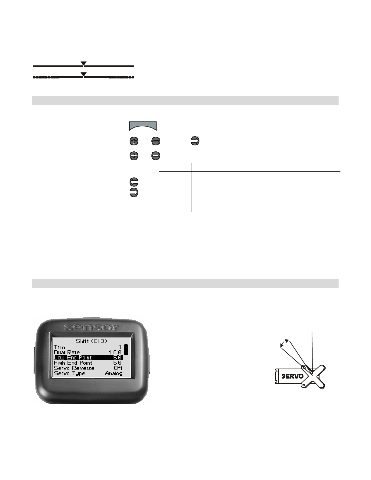
Cha nging the dua l r ate s etting ha s the following vis ua l effec t on the d r iving scr een bars :
Full servo range is used.
Lowe r dual ra te value reduces servo range.
Ad j usting Shift Se r vo D ua l Rat e
Use the navigation controls to adjust shift servo dual rate as follows:
1. Access the top function menu
from the driving screen.
2. Navigate to the Shi ft (Ch3)
menu.
3. Navigate to Dual Rate.
4. Change the value.
menu
or : then
or
or
Value Description
0 Shift servo range is set to minimum (0%).
1-99
100 Shift servo ra nge is set to full (100%)
Shift servo range is set to a percentage of full range.
For example, value “50” gives 50% of full servo
range.
Dual Rate and End Point Adjust ment
Full s erv o r ange is determined by the s hift servo lo w and high end point adjustme nts. The dual
rate value determines the relative servo range between the low and high end points. The
ser vo will never move beyond the s et end point adjustments, no m at ter what dual ra te se ttin g
is applied.
Low End Point
The s hift ser vo low end point
valu e ad justs t he shif t serv o’s
startin g position at reset. Th is is
intended to be low gea r a nd
go es wi th the dow ns hi ft s ound
event. The end point
ad justm ents sh ou ld be adjusted
prior t o other settings.
The lo w end point is s et
independently of the high end
p oin t (wh ich adjusts how far
the shift servo moves t o the
HIGH end).
48
Page 52
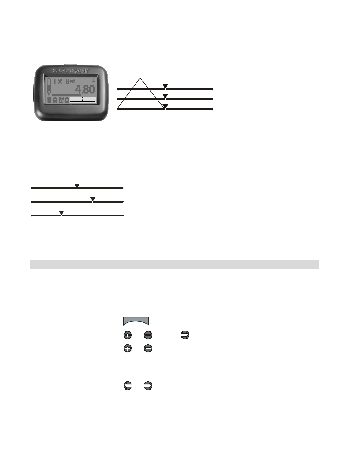
On the dri ving screen,
the low end point is
represented by the
length of the bar to the
left of the pointer on
t he lower bar.
Low End Point
S teering (Ch1)
Throttle (Ch2)
Shift (Ch3)
The greater the left
length of the bar, the
greater the low end
point value.
The position of the
pointer on the bar is
affected by end point
settings (l ow and
high) and trim
setting.
Changing t he low end point value has the following visual effect on the driving screen bars.
Low end point value is approximately the same as the high end point
value.
Increased low end point value (more servo travel on LOW e nd is
possible).
Decreased low end point value (less servo tra vel on LOW end is
possible).
The position of the pointer on the bar is affected by end point settings (low
and high) a nd tr im s e t ting; incr e a s ing the lo w e nd point va lue m a y v i sua lly
appear t o have the same eff ect as decreasing t h e h igh end po int value.
Adjust ing the Low E n d Point
The low end point value is a relative value, and is expressed as the percentage of full t ravel to
the LOW end. For example, setting t he low end point value to “50” allows the servo to move
only 50% of full travel t o the low end.
U se the na viga tion controls to adj ust the low end point a s follows :
1. Access the top function menu
from the driving screen.
2. Navigate to the Shi ft (Ch3)
menu.
3. Navigate to Low End Point.
4. Change the value.
menu
or : then
or
or
Value Description
0
1-99
100
Minimum low end point; allows NO travel to low
end.
Low end point value is set to a percentage of
travel range to low end.
For example, a value of “50” gives 50% of full
travel to low end.
Maximum low end point; allows FULL travel to low
end.
49
Page 53
Tri m and EPA In te ract ion
A trim (or sub-trim) setting of 100 is equivalent to an End Point setting of 20.
High End Point
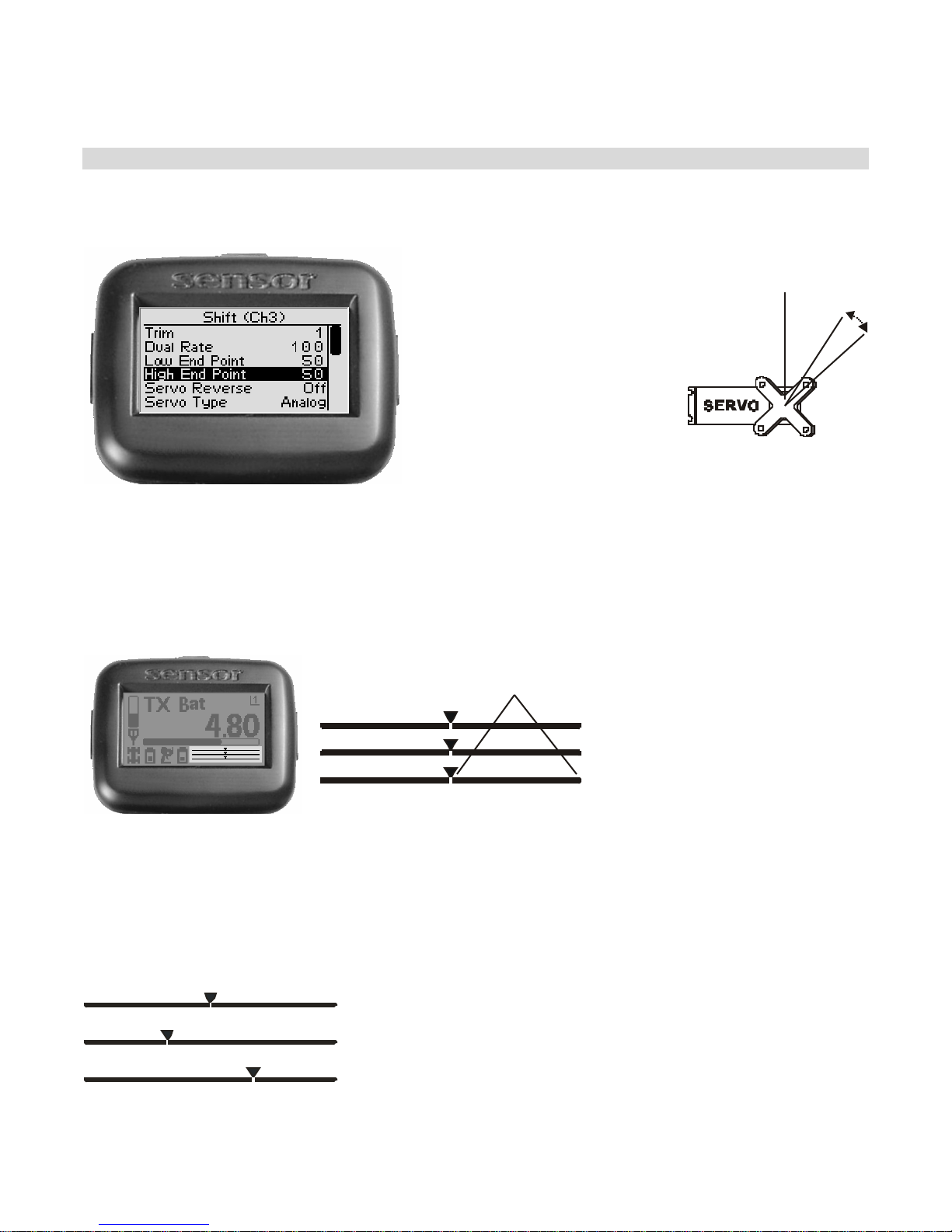
The shift servo high end po in t
valu e ad justs t he shif t serv o’s
ending posit ion after shifting
upwar ds. This is intended to
be high gear and goes wit h
th e u ps h ift s ou n d ev e nt. Th e
end p oint ad just m e nts sh ould
be adjusted prio r to other
sett ings.
The high end po int is set
independently of the low end
p oin t (wh ich adjusts how far
the shift servo moves t o the
LOW turns end).
On the dri ving screen,
the high end poi nt is
represented by the
length of the bar to the
right of the pointer on
the upper bar.
High End Point
S teering (Ch1)
Throttle (Ch2)
Shift (Ch3)
The greater the right
length of the bar, the
greater the high end
point value.
The position of the
pointer on the bar is
affected by end point
settings (l ow and
high) and trim
setting.
Changing the high end point value has the following visual effect on the driving screen bars.
High end point value is approximately the same as the low end point
value.
Increased high end point value (more servo travel on HIGH end is
possible).
Decreased high end point value (less servo travel on HIGH end is
possible).
50
Page 54
The position of the pointer on the bar is affected by end point settings (low
and high) a nd tr im s e ttin g; incr e a s ing the high e nd point va lue m a y vis ually
appear t o have the same eff ect as decreasing t h e low end point v alue.
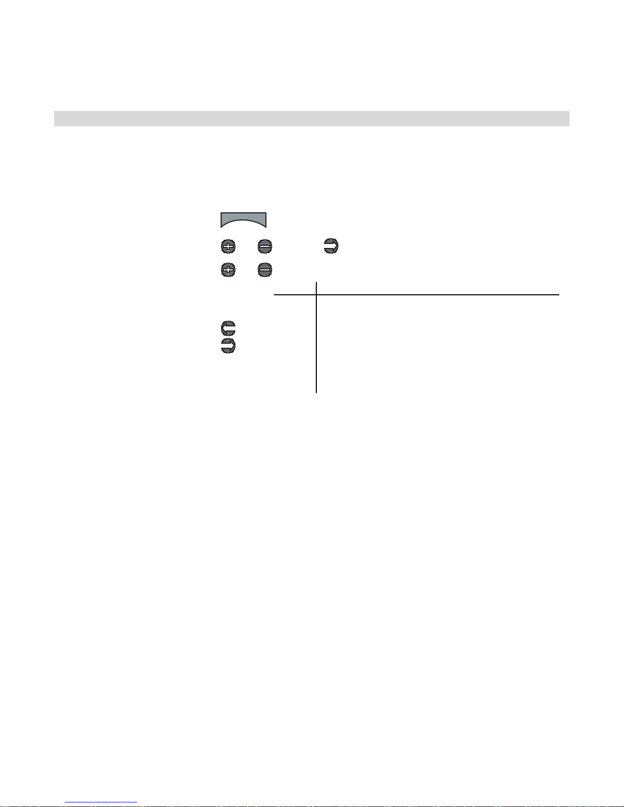
Adjust ing the H igh E n d Point
The high end point value is a relative value, and is expressed as the percentage of full t ravel
to the HIGH end. For example, setting the high end point value to “50” allows the servo to
move only 50% of full travel to the high end.
Use the navigat ion controls to adjust the high end point as follow s:
1. Access the top function menu
from the driving screen.
2. Navigate to the Shift (Ch3)
menu.
3. Navigate to High End Point.
4. Change the value.
menu
or : then
or
or
Value Description
Mini mum high end point; a llows NO tr avel to hi gh
0
end.
High end point value is set t o a percentage of
1-99
100
travel range to high end.
For example, a value of “50” gives 50% of full
travel to high end.
Maximum high end point; allows FULL travel to
hi gh end.
Tri m and EPA In te ract ion
A trim (or sub-trim) setting of 100 is equivalent to an End Point setting of 20.
51
Page 55
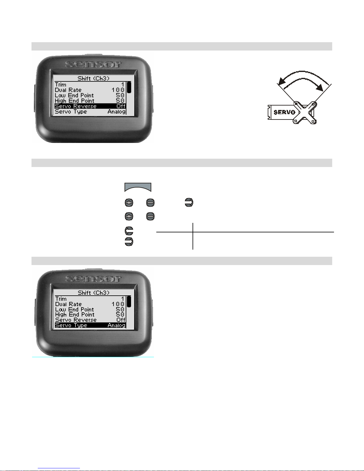
Shift Servo Reverse
Shif t serv o reve rsin g reverses
the d ir e ction the s h ift s e r vo
moves upon receiving an input
from the grip buttons.
Cha n ging the Shif t Ser v o Re ve rse Se t ti ng
Use the navigation controls to change the shift servo reverse setting as follows:
1. Access the top function menu
from the driving screen.
2. Navigate to the Shift (Ch3)
menu.
3. Navigate to Servo Reverse.
4. Change the value.
menu
or : then
or
or
Value Description
Off Standard servo direction.
On Reverse d servo direction.
Shift Servo Type
Shift servo type lets you select the type of shift servo
(analog or digital) in the vehicle. Analog se rvos are
sent sig nals at 50 frames/sec, while D ig ital se rv os are
sent sig nals at 100 frames/sec.
52
Page 56
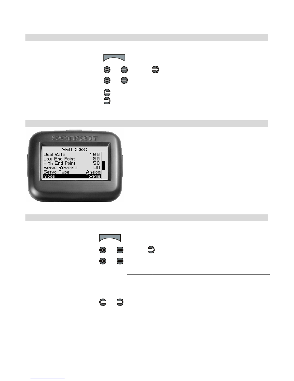
C hanging th e Sh if t S er vo T ype
Use the navigation controls to change the shift servo type as follows:
1. Access the top function menu
from the driving screen.
2. Navigate to the Shi ft (Ch3)
menu.
3. Navigate to Servo Ty pe.
menu
or : then
or
or
Value Description
Analog Shift servo is analog. 4. Change the value.
Digital Shift servo is digital.
Shift Servo Mode
Shift servo mode cont rols the operation of the shift
function.
C hanging th e Sh if t S er vo M ode
Use the navigation controls to change the shift servo mode as follows:
1. Access the top function
menu from the driving screen.
2. Navigate to the Shi ft (Ch3)
menu.
3. Navigate to Mode.
4. Change the value.
menu
or : then
or
or
Value Description
Off No action; shift servo stays at trim position.
Toggle
Hold
4WS
Thr/Brake
Shift servo starts at Low. Pressing the grip button
moves the shift servo to High. Releasing and
pressing the grip button again moves the shift servo
ba ck to Low.
Servo starts at Low. Holding the grip button moves
the shift servo to High. Releasing the grip button
moves the servo back to Low.
4-wheel steering mode. Shift servo output is
controlled by the steering wheel, just like the
steering servo.
Throttle/Brake mode. Shift servo output is controlled
by the trigger, just like the Throttle servo
53
Page 57
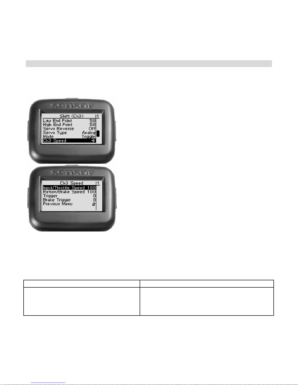
Note that in 4W S or T hr/Brake mode the settings on t h is scre en (En d Po ints, Dual Rate, Trim,
Rever se, Type, and Servo Sp eed) still take effec t. The Ex po s ettin g from the master c hannel is
used , f or Th r/B rak e Auto St art , Idle Up, and AB S apply.
Ch3 Speed
Ch3 sp eed allows you t o limit the maximum speed th at
the shift servo will be driven to match your movements
on the button. There are four parameters that can be
adjusted to precisely set up yo ur limiting.
I nput/ Thr o ttl e Sp eed de ter mines the p erc en tage of ful l
s p e e d th at i s a p p lied to the thro ttle mov e ments th at a re
above the thrott le trigge r setting. 100 is maximum servo
moveme nt rate. 1 is minimum rate. Def au lt is 100 (full
speed)
Re tu rn/B rake Speed determ in es the percentag e of fu ll
s peed that is appl ied to bra ki n g movemen ts t ha t are
abo ve th e trigger sett ing. 100 is maximum servo
moveme nt rate. 1 is minimum rate. Def au lt is 100 (full
speed)
Trigger sets th e minimum amount o f contro l input be fore
the s p eed lim iter bec omes active. At 0%, limiting is
always active ( in put is alw ay s >= 0%) . At 50% , limiting
is only active if the thro ttle is half way or mor e .
Brake Trigge r set s the minimum amou nt o f control input
befor e the s pe ed limiter becomes active. At 0%, limitin g
is alw ays act ive (input is always >= 0%). At 50%,
limiting is only active if the br ake is ha lf way or mor e .
The parameters o f this function operate differently depending on which mode CH3 is currently
set for. (See Shift Servo Mode abo ve).
Shift Servo mode set for 4WS Shift Servo mode set for Thr/Brake
Input/Throttle Speed acts as Input Speed
Re tu rn/B rake Speed acts as Return Spe ed
Trigger acts as Trigge r
B r ake Trigg er is not used
Input/Thrott le Speed is Thrott le Spee d
Re t urn/B rake Spe ed acts as Brak e Speed
Trigger acts as Throttle Trigger
Brake Trigger acts as Brake Trigger
54
Page 58
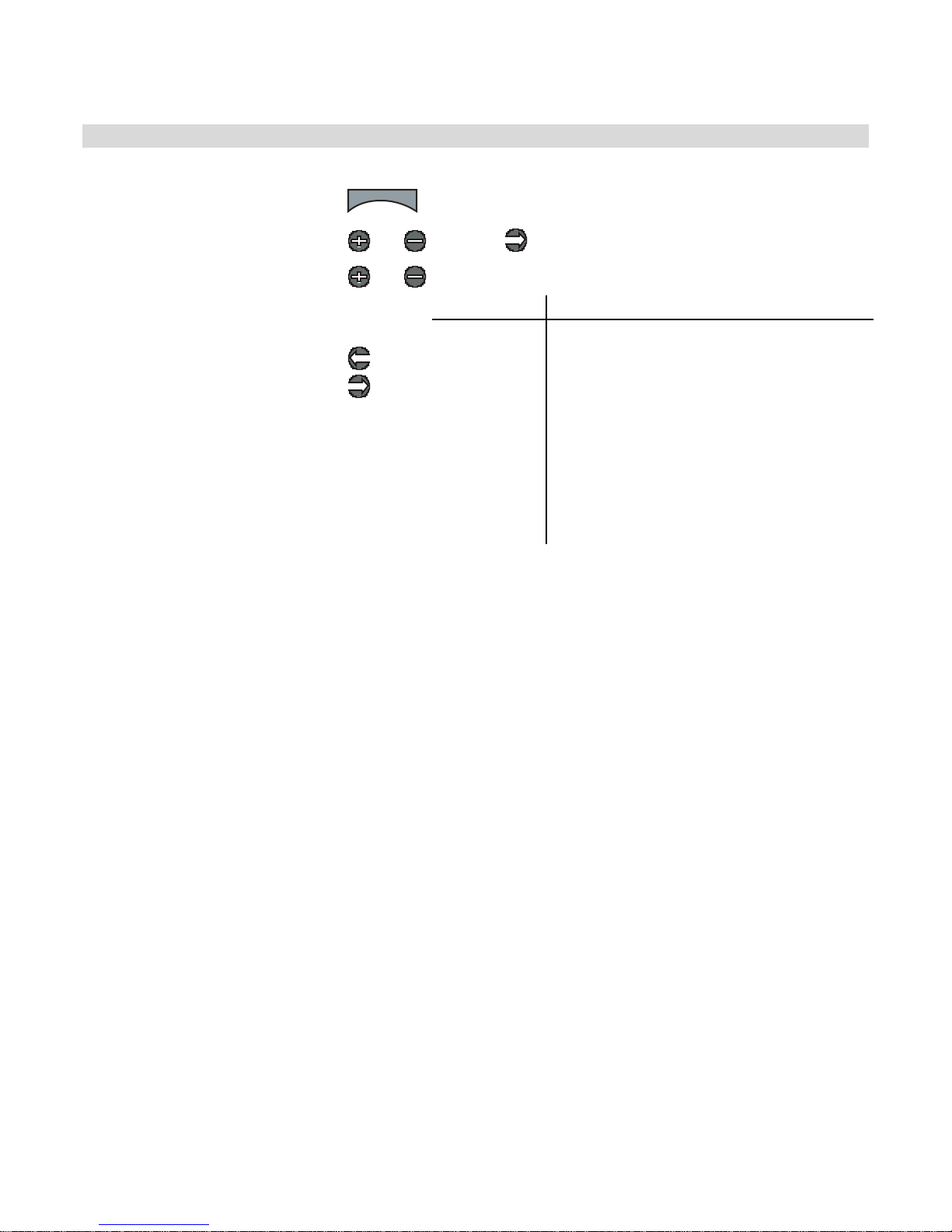
Changing the Ch3 Speed
Use the navigation controls to change the steering servo type as follows:
1. Access the top function menu
from the driving screen.
2. Navigate to the Steering (Ch1)
menu.
3. Navigate to Throttle Speed.
4. Change the values.
menu
or : then
or
or
Value Description
Input/Throttle
Speed
Return/Brak e
Speed
Trigger
Brake Trigger
The amount of limiting applied to servo
throttle motion once the trigger amount has
been exceeded.
The amount of limiting applied to servo
bra ke motion once the trigger amount has
been exceeded.
The percentage of full throttle range that will
be limited.
The percentage of full braking range that will
be limited.
I nter a c ti on wi t h o ther Se t tings
• Servo Speed does not apply t o CH3 when in Toggle, Hold, or Off modes
• Servo Speed is applied after Expo. The trigger levels refer to the curved input value.
• ABS is applied after Brake Speed, so Brake Speed can lim it how quickly the brake input
moves to the ABS Act ive region, but once there ABS pulses happen at full speed.
• Ser vo Sp eed is a pplied after Au toStart, so if the A u toStart Level is set higher than the
Thro ttle Speed Tr igger, the s ervo movement will be s lowed.
• Idle Up only takes effect when the trigger is centered. Throttle Speed can slow down
the return to center and t herefore slow dow n Idle Up activation. Once Idle Up is
started, the servo will j um p to the set p os ition.
55
Page 59
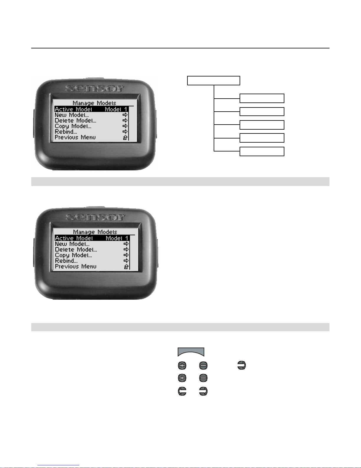
Model Management
The following illus tration shows the function me nu str ucture fo r th e mo del ma nageme nt
functions:
Manage Models
Active Model
New Model
Delete Model
Copy Model
Ac tiv e M ode l
Rebind
T he Sensor can st o re all settings for up to eight
vehicles. The Active Model function is used to select
the mo del to be used.
Whe n b in din g w ith a tran sceiver in a v eh icle , yo u
must first select the active model to identify the
vehicle .
When preparing to operate a vehicle, select the
active model, then turn on the vehicle and Sensor.
Th e S e nsor s ea rch es fo r t he tr ans cei v er with th e
VIN associated with the selected active model.
Fo r m ore in form at ion , se e “The B in din g Process”
earlier in th is ma nual.
S e le c ting the A ctiv e Mode l
U se the na viga tion controls to select the ac tive model a s follows:
1. Access the top function menu from the dri ving
screen.
2. Navigate to the Manage Models menu.
3. Navigate to Active Model.
4. Select the active model.
menu
or : then
or
or
56
Page 60
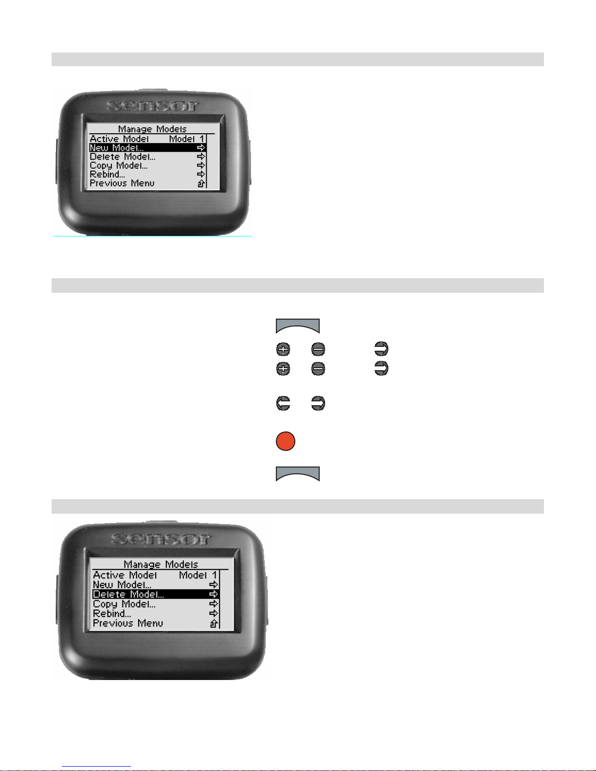
Ne w Mo del
Y ou can create a ne w m odel se ttin gs pr ofile if there
are any model me morie s re maining. Creating a new
model a llows y ou to stor e the settin gs for a no ther
model.
By default, the new model setting is given the
numbe r of the next highest model numbe r (For
example, if there are current ly 4 model settings,
creat ing a new model will create “Model 5” and make
it t he defa ult model.)
You can change the model name from your PC using
the Digital RC Desktop.
Creating a New Mod el
U se the navigation c ontrols to create a new model as follows:
1. Access the top function menu from the dri ving
screen.
menu
2. Navigate to the Manage Models menu.
3. Navigate to and activate New Model.
4. At the confirmation screen:
• Select Yes to create a new default
model.
• Select No to cancel the operation.
5. Confirm your selection.
6. The “connecting” screen appears.
You can press the “Menu” but ton to cancel .
De le te M o del
or : then
or : then
or
OK
menu
Y ou can delete a model se ttin gs pr ofile. T his
removes a ll s tor ed se ttings for the model from
memory.
57
Page 61
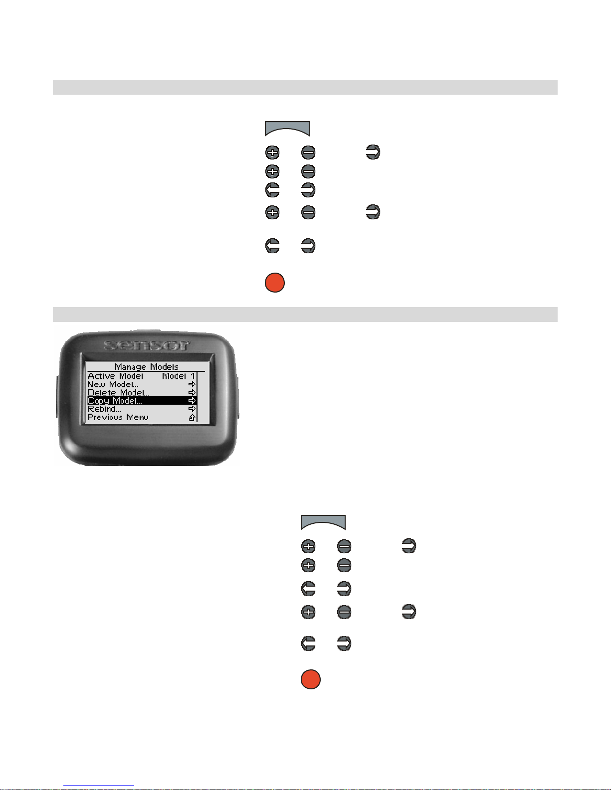
De le ting a Mode l
U se the na viga tio n controls to dele te a model as follows:
1. Access the top function menu from the
driving screen.
menu
2. Navigate to the Manage Models menu.
3. Navigate to Active Model.
4. Navigate to the model you want to delete.
5. Navigate to and activate Delete Model.
6. At the confirmation screen:
• Select Yes to delete the active
model.
• Select No to cancel the operation.
7. Confirm your selection.
Copy Model
or : then
or
or
or : then
or
OK
You can copy settings from one model profile to create a
ne w d uplicate mo del. If all model profiles alr eady exis t,
you cannot copy a model.
Copying a Model
U se the navigation c ontrols to c opy a mod el as follows:
1. Access the top function menu from the dri ving
screen.
2. Navigate to the Manage Models menu.
3. Navigate to Active Model.
4. Navigate to the model for which you want to copy
the settings.
5. Navigate to and activate Copy Model .
6. At the confirmation screen:
• Select Yes to create a new dupli cate model .
• Select No to cancel the operation.
7. Confirm your selection.
8. A ne w duplicate mode l is created a nd set as ac tive model.
menu
or : then
or
or
or : then
or
OK
58
Page 62
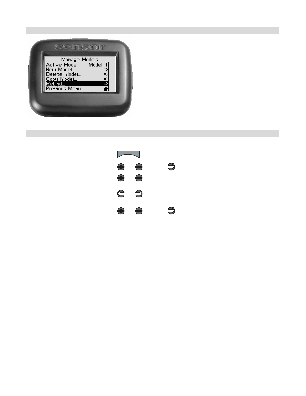
Rebind ing
Y ou can re bind to the tra nsceiver in a specific model
(identified by a model profile).
Rebinding to a Model
U se the c ontrols to rebind t o a mo del a s follows:
1. Access the top function menu from
the driving screen.
2. Navigate to the Manage Models
menu.
3. Navigate to Active Model.
menu
or : then
or
4. Navigate to the model you want to
re bind wit h.
5. Navigate to and activate Rebind.
6. I f the recei ver was previously boun d to a dif ferent Se nsor, turn on the mode l and perform the binding process
again by activating the Bind button until the LED illuminates. Otherwise, just turn on the model.
or
or : then
59
Page 63
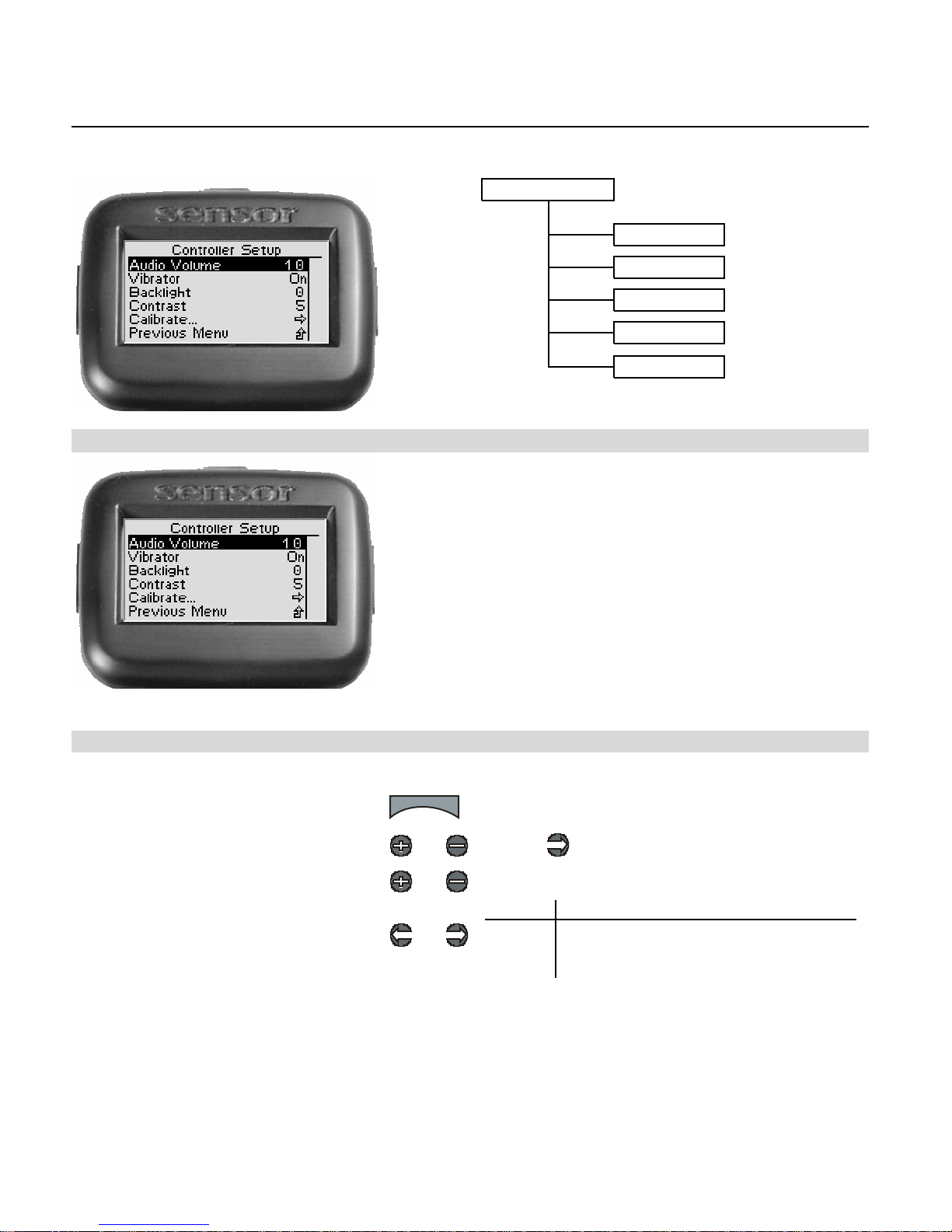
Controller Setup
The following illus tration shows the function me nu str ucture fo r th e c ontroller s e tup functions:
Controller Setup
Audio Volume
Audio Volume
Vibrator
Backligh t
Contrast
Calibrate
0 - 11
Off, On
0- 10
0- 10
Yo u can s e t t he au dio v olum e to on e of eleven se tti n gs .
While ma ny RC controllers let you adjust the so und to
just ten set tin gs, Sensor gives you one more. It’s one
louder.
S e tting the Audio V olu m e L e ve l
U se the navigation c ontrols to se t the a udio volume as follows:
1. Access the top function menu from the
driving screen.
2. Navigate to the Controller Setup
menu.
3. Navigate to Audio Volume.
4. Adjust the volume level.
menu
or : then
or
or
Value Description
0 - 11
0 mutes the volume.
1 is lowest volume.
11 is highest volume.
60
Page 64
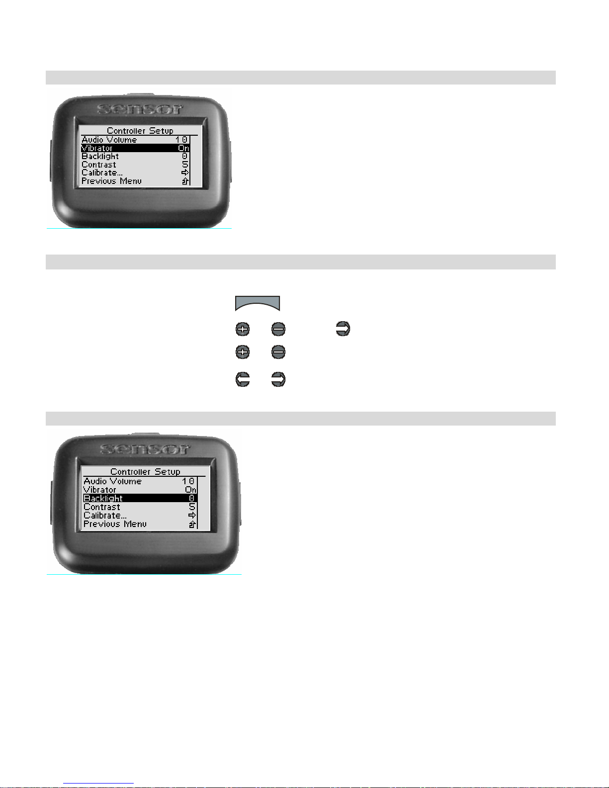
Vibrator
As you might guess, this option lets you turn the vibration
option on and off.
Turning the Vibrat or On/Off
Use the navigation controls to turn the vibrator on/off as follows:
1. Access the top function menu from
the driving screen.
2. Navigate to the Controller Setup
menu.
3. Navigate to Vibrator.
menu
or : then
or
4. Turn the vibration option on/off.
Ba cklight
or
You can set the brightness of the display screen
back l ight. The use of the back l ight cons um es po w er and
will r ed uce the running t ime of your Sensor co ntroller.
61
Page 65
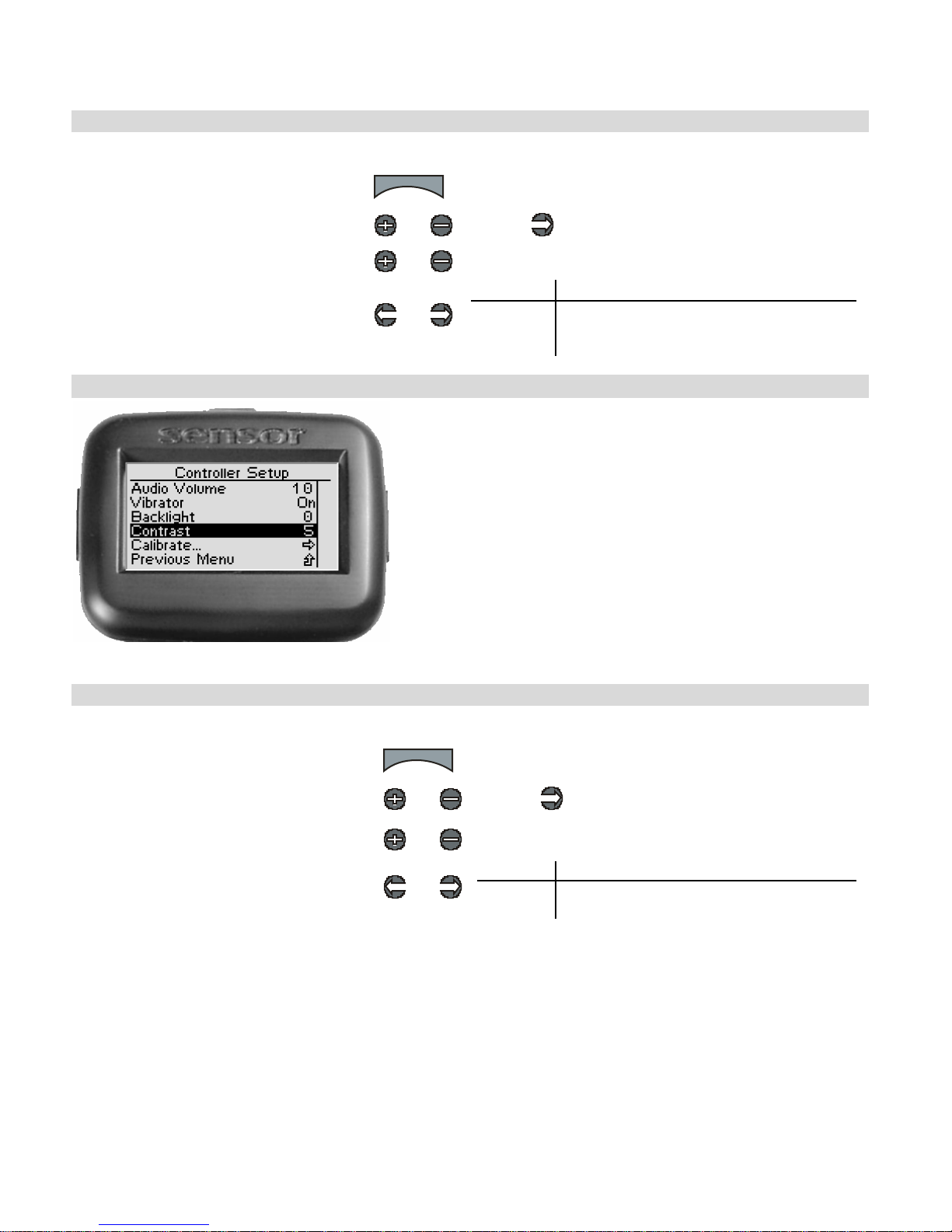
Ad j ust ing the D is pla y B a ck light L e ve l
U se the na viga tion controls to a djust the display ba cklight level as follows:
1. Access the top function menu from the
driving screen.
2. Navigate to the Controller Setup
menu.
3. Navigate to Backlight.
4. Adjust the display screen backlight
level.
menu
or : then
or
or
Value Description
0 - 10
0 turns backlight off. (Maximum battery
life)
10 is the brightest backlight level.
Cont rast
You can set the contrast of the display screen to make
it lighter or darker for better visibility at your preferred
vie wing angle.
Adj usting the D is pla y C o ntras t Leve l
U se the naviga tion controls to a djust the display contras t level a s follows:
1. Access the top function menu from the
driving screen.
2. Navigate to the Controller Setup
menu.
3. Navigate to Contrast.
4. Adjust the display contrast level.
menu
or : then
or
or
Value Description
0 - 10
0 is lowest contrast level (faintest).
10 is the highest contrast level (darkest).
62
Page 66
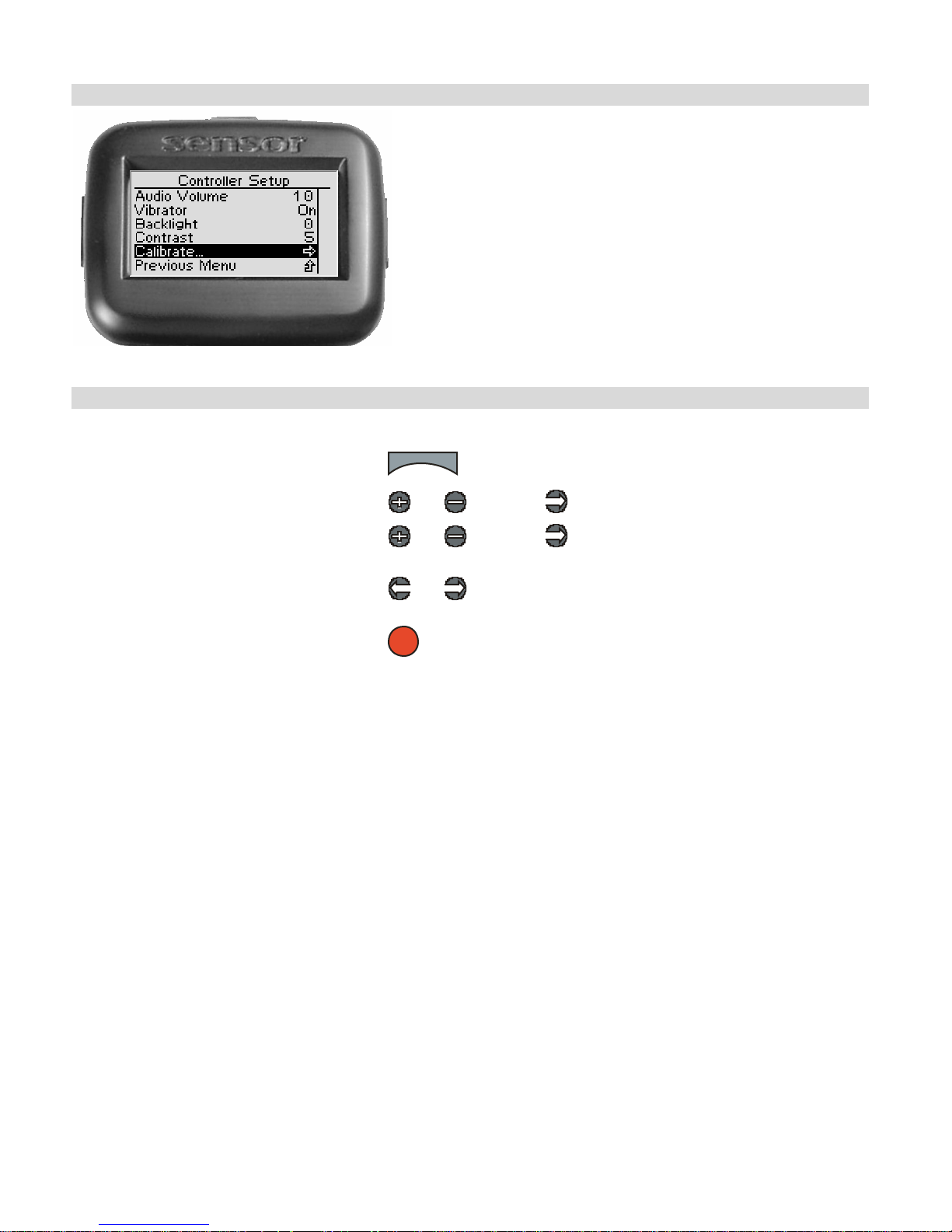
Ca libr ate
You can recalibrate the Sensor steering and throttle
controls. This does not change any of the steering or
thro ttle settin gs that a r e store d in the mem ory pr ofile.
Rec a librating the Sensor
Use the navigation controls to recalibrate the Sensor as follows:
1. Access the top function menu from the
driving screen.
2. Navigate to the Controller Setup
menu.
3. Navigate to and activate Calibrate.
menu
or : then
or : then
4. At the confirmation screen:
• Select Yes to recali brate
• Select No to cancel the operation
5. Confirm your selection.
6. Perform the calibration routine by following the on-screen commands.
or
OK
63
Page 67
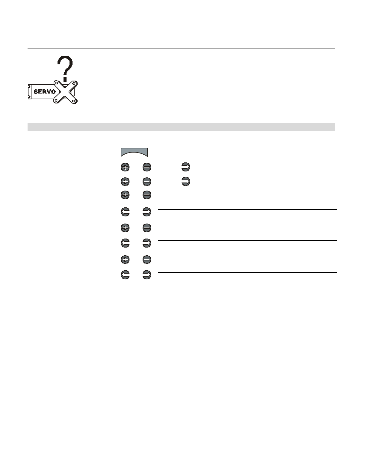
Failsafe s
Y ou c an s e t u p the fai lsa f e po si tion s o f the serv os s o th at in the e vent
o f lo ss of sig nal, the serv os go t o t heir set failsaf e p ositio ns. De fault
failsafe p ositio ns are ce ntered steering and t rim.
S e tting Fails a fe M ode s
U se the na viga tio n controls to s e t the failsafe modes a s follows:
1. Access the top function menu
from the driving screen.
2. Navigate to the Advanced
menu.
3. Navigate to the Failsafe
menu.
4. Navigate to Steering.
5. Change the steering servo
fails afe set ting .
6. Navigate to Throttle.
7. Change the throttle servo
fails afe set ting .
8. Navigate to Shift.
9. Change the shift servo
fails afe set ting .
menu
or : then
or : then
or
or
or
or
or
or
Value Description
Hold Steering servo holds last known position.
Set Steering servo goes to set failsafe position.
Value Description
Hold Throttle servo holds last known position.
Set Throttle servo goes to set failsafe position.
Value Description
Hold Shift servo holds last known position.
Set Shift servo goes to set failsafe position.
64
Page 68

Set ting Failsafe P ositio n s
Use the navigation controls to set the failsafe positions as follows:
1. Access the top function menu from the
driving screen.
menu
2. Navigate to the Advanced menu.
3. Navigate to the Failsafe m enu.
4. Navigate to Set Failsafes.
or : then
or : then
or
5. At the confirmation screen:
• Select Yes to capture the servo
fails afe set ting s.
or
• Select No to abandon the
operation.
6. Confirm your selection.
OK
7. A 3-second countdown be gins on the di splay screen.
Before the countdown ends, use the Sensor controls to set the servo failsafe positions. (For example, on a nitro car
set steering to centered and throttle to full brake.)
At the end of the countdown, a confirmation message indicates that the servo failsafe positions were stored.
8. To test the failsafe positions, turn off the Sensor and observe the reactions of the connected servos. The servos
should go to the failsafe positions you just set.
65
Page 69

Sensor Digital RC Desktop
The innovative Sensor Digital RC Desktop can be used to program the functionality of your
Sensor using your computer. The supplied adaptor cable is used to connect your Sensor to an
available USB port on your computer, allowing your Sensor and the RC Desktop to communicate
and exchang e info rm atio n. The RC D eskt op interface has t he sam e menu structure as t hat
contained within yo ur Sensor; and has been de signed to be very easy to use.
Informat ion may be t ransferred between your Sensor and t he RC Deskt op so that you can
download your c urrent setting inform atio n to your c omputer, ma ke c ha nges , and then upload
the newer settings. Updating the Sensor firmw are is as easy as uplo ading a file, or using yo ur
Interne t connection t o r etrieve th e latest fir mwar e file dir ec tly from Nom adio and upload it to
your Sensor in one easy step.
After you start using your Se nsor and install your RC Desktop, we strongly recommend that yo u
perform the registration process so that you can receive special incentives and privileges, and
be kept abreast of the late st Nomadio developments and news. The online registration process
is fast and easy, and requires an Internet connection.
Minimum System Requirements
Processor: Pentium 3
RAM: 128MB
HDD space: 100MB
CD-ROM: Available CD-ROM drive
Display: VGA or better
Ports: Available USB port (1.1 or 2.0 port
recommended)
OS: Windows 2000, XP
Installing the RC Desktop
1. Install the Nomadio Digital RC Desktop CD into your computer’s CD-ROM drive.
2. If your computer has AutoPlay enabled, the installation wizard begins automatically.
If AutoPlay is not enabled, locate and r un the RCDesktopSetup.exe file located in the
ro ot directory on t he C D -ROM.
66
Page 70
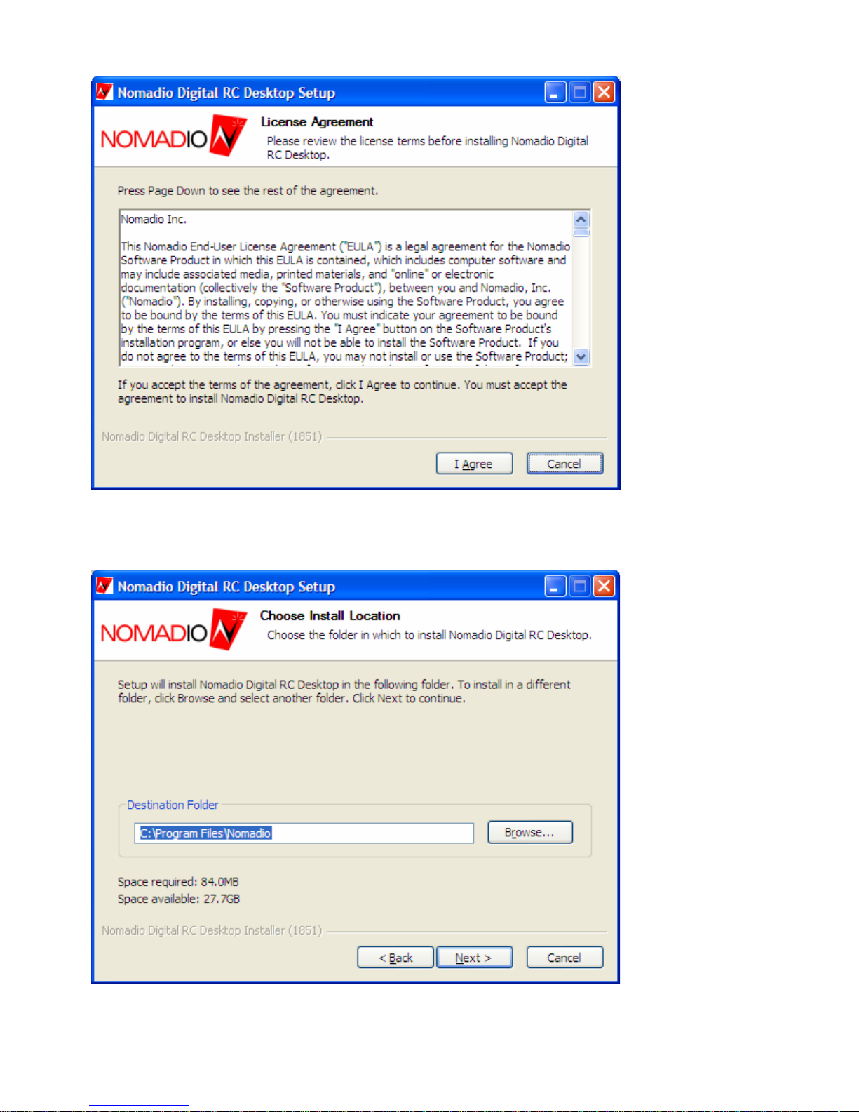
3. When the installa tion be gins you will be present ed with a Setup Wizar d that b egins with
the Nomadio License Agreement. Click I Agree to co n ti nue.
67
Page 71
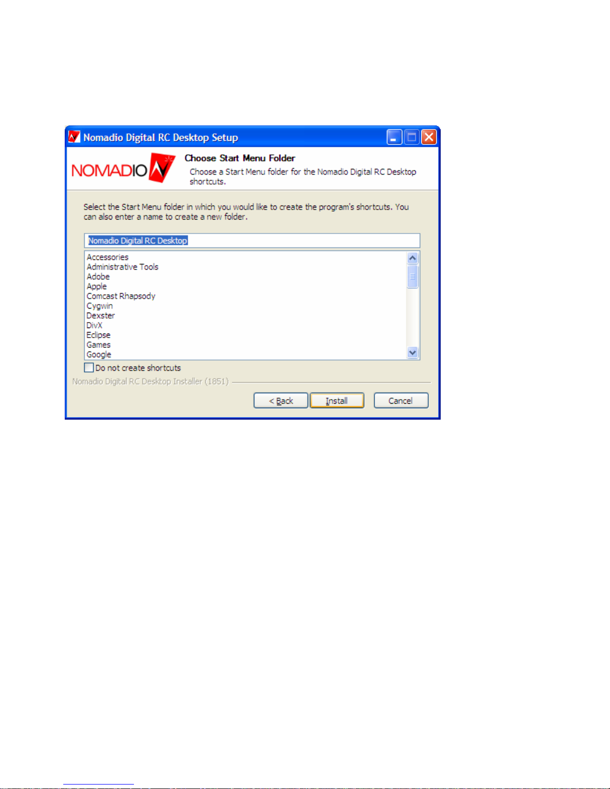
4. N ext ch o os e the d estina tion fold er for the D igital R C D esk top by either typing in the path
or click ing the Browse button and picking the folde r you w ish to use. Click the Next
bu tton to co n ti nue.
5. At the next screen, select the Start Menu folder for the Digital RC Desktop’s shortcuts.
Click the Do not create shortcuts c heckbox if you do not want s hor tcuts cre ated. Click
Install to continue the Setup Wizard.
68
Page 72
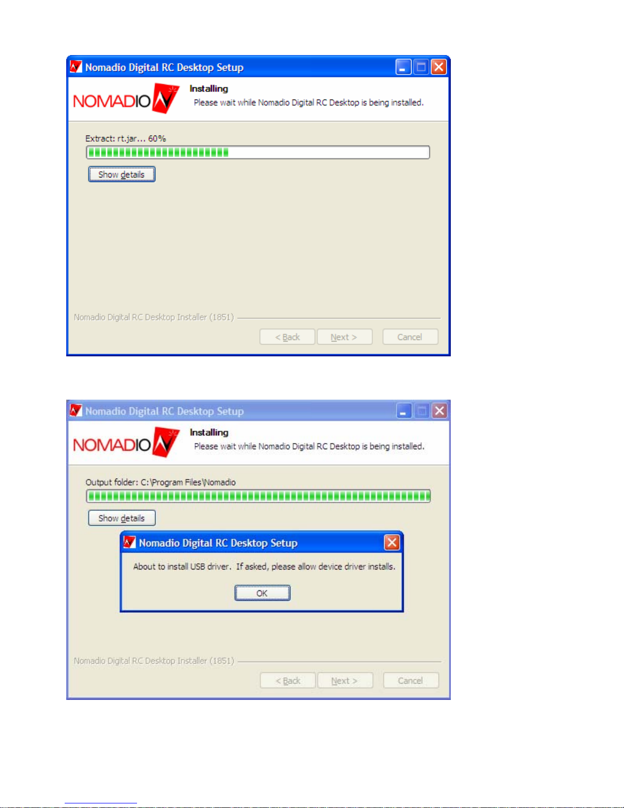
6. The Setup Wizar d will next install all of the files required.
7. Aft er installing the requir ed files, the Setup Wiza r d will install the Univers al Serial B us
de v ic e drive rs t h a t wi l l a l lo w the D igita l R C De s kto p to c ommun ica te with the S en s o r.
69
Page 73
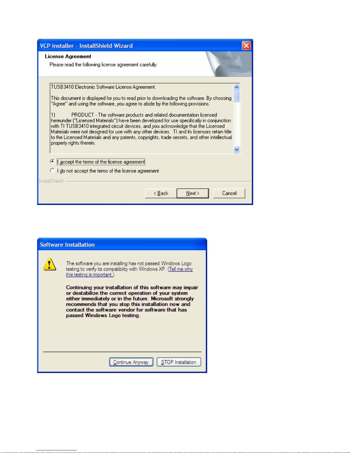
8. Y ou will th en be sho wn the Lic ens e Agre ement for th e device dr ivers. C hoose I accept
th e terms of t h e license agreement and then click Next to co n tinue.
9. On Windows XP you will be prompted if you want to install each of the two dev ice
dr ivers . Noma dio is actively working towards achieving Windows Logo Certificatio n a nd
currently pass es a ll th e required tests available fr om Windows H ar dwar e Q ua lity Labs.
Click Conti nue An y wa y to continue the installation.
70
Page 74

10. Once the device drivers are installed, click Finish to compl e te the device driver se tup.
11. D igital RC Desktop Setup is now alm os t d one. Click Next to conti nue .
71
Page 75
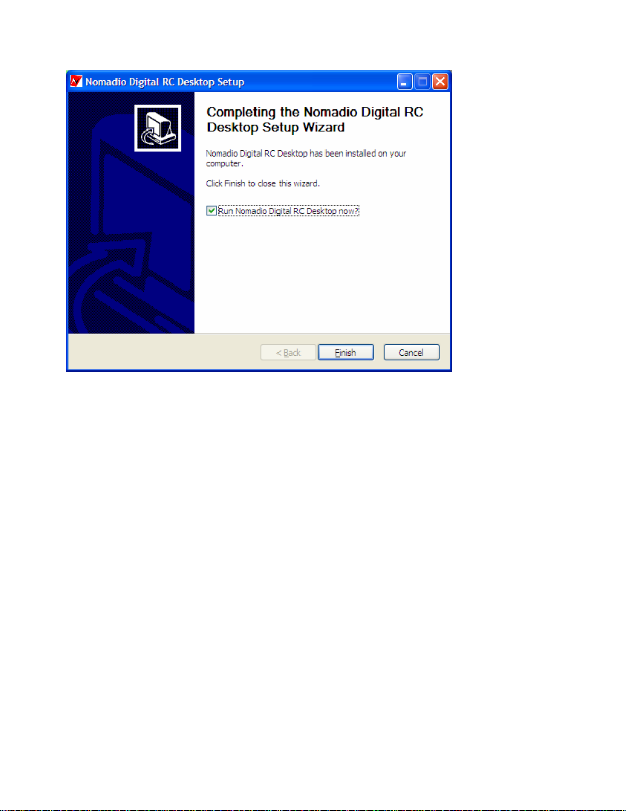
12. Leave the Run Nomadio Digital RC Desktop now? ch e ck box s electe d fo r the Setup
W izard to launch the program after exiting t he Setup Wizard. Click Finish to exit th e
Nomadio Digital RC Desktop Setup.
72
Page 76
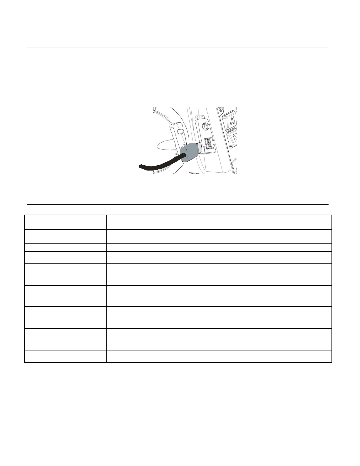
Connecting the Sensor to your Computer
To conn ec t your Se ns or to your compu ter, do the f ol l owi ng:
1. Plug the small end of the supplied adaptor cable into the recept acle on t he left side of
the S e n sor.
2. Plug the other end of the cable into an available USB port on your computer.
Y our c omput er will recognize the Senso r as being co nnected via a ne w ser ial
communications port.
Using the Sensor Digital RC Desktop
To start the RC Desktop
To make changes to the
settings
To open a saved settings file
To save the curr ent settings
into a file
To recei ve the current
settings from the Sensor
To send the RC Desktop’s
cur r ent settings to the Sensor
To install the l atest firmwar e
into th e Sen so r
To install firmware from a file
into th e Sen so r
To update the RC Deskto p to
the l atest version
From the START menu, click (All) Pr ograms, Nomadio Digital RC Desktop,
then Nomadio Digital RC Desktop.
Navigate through the functions of the RC Desktop, and make changes as
a pprop r iate to gl obal settin gs, or to setti ngs for individual models.
From the File menu, click Open ….
From the File menu, click Save.
1. Connect the Sensor to your computer.
2. Tur n on the Sensor.
3. From the File menu, click Receive Sett ings from Sensor.
1. Connect the Sensor to your computer.
2. Tur n on the Sensor.
3. From the File menu, click Send Settings to Sensor.
1. Connect the Sensor to your computer.
2. Tur n on the Sensor.
3. From the Firmware me nu, cl ick Install Latest Firmware.
1. Connect the Sensor to your computer.
2. Tur n on the Sensor.
3. From the Firmware me nu, cl ick Install Firmware from File.
From the Help menu, click Software Updates.
73
Page 77
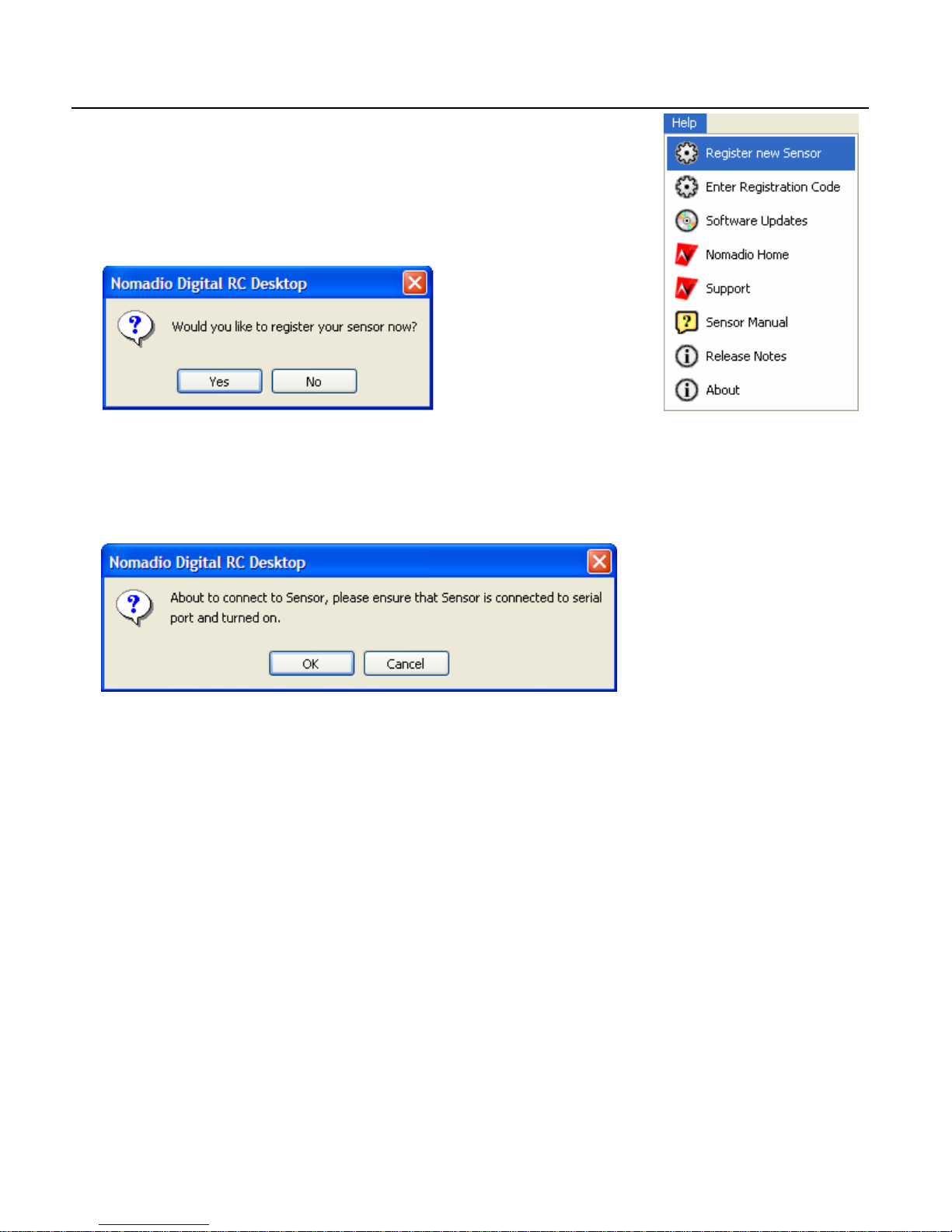
Registration
1. When you start the Digital RC Desktop the first time, you will be prompted to register.
Click Yes to continue. If you click No, you can register you w ill be prompted again the
next time you start the Digital RC Desktop. You can re gister immediate ly by c hoosing
the Help me nu and then c hoosing Re gi s ter ne w Sens or .
2. The Digita l R C Des ktop will now read your Sensor ’s I D. Conn e ct a nd turn on your Sens or
and click OK.
74
Page 78
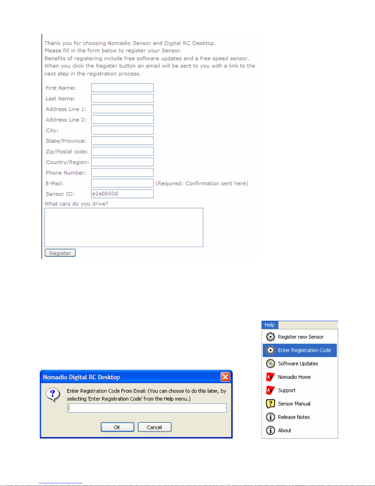
3. Your web browser will then be opened to a web page that will ask you for registration
infor matio n. Y our Sensor ID will be a u tom atica lly rea d from your Sensor and filled in.
4. When you c lick the Register button, a confirmation e-mail w ill be sent to you. T his will
e-ma il will c ontain a link ba ck to Nom a dio’s r eg is tration s ite where you will be able to get
your reg istration code.
75
Page 79
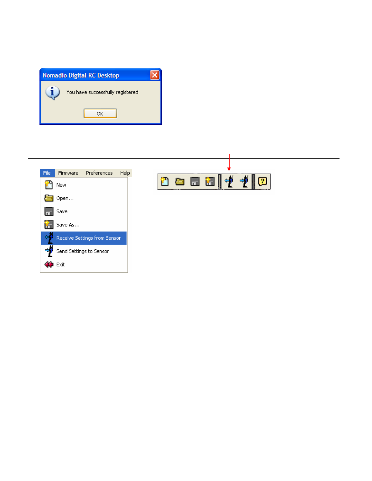
5. Enter your registration code in the Digital RC Desktop and click the OK button. If you
press Cancel, you can ente r your registration code by choosing the Help menu and
choosing Enter R e g istrat ion Cod e.
6. You are now registered.
Receiving Settings From the Sensor
The Digital RC Desktop will attempt to re ceive settin gs from
the Sensor on startup. You can also choose the File menu
and then choose Re c e iv e Se t tings f rom Se nso r . Fina lly
you can choose the Receive Settings From Sensor toolbar
button.
1. The Digital RC Desktop will then connect to your
Sensor and download the settings from it.
76
Page 80
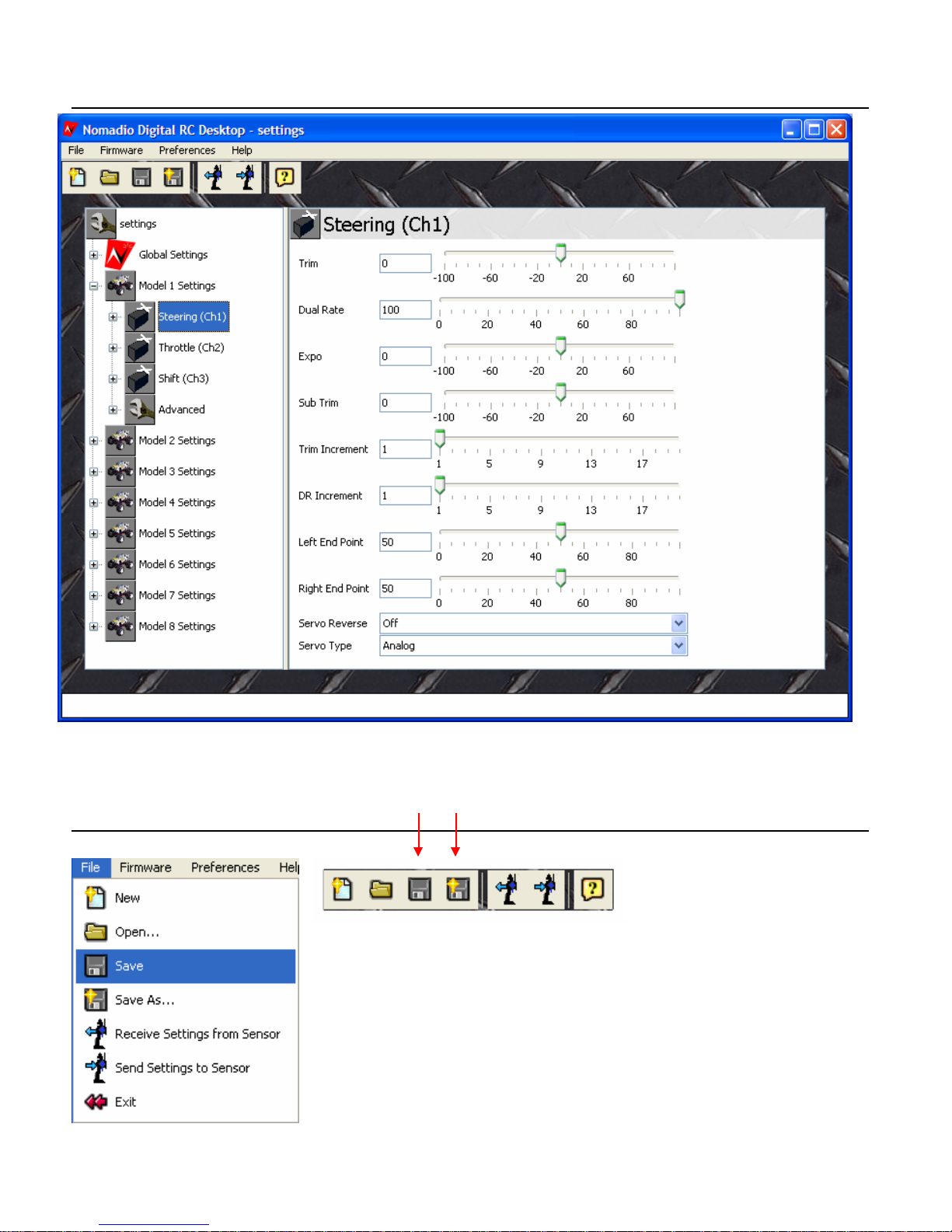
Editing Settings
Simply use the set tin gs m enu on the left sid e of t he screen to fin d the set tin gs yo u w ish to ed it.
Individual se tt ings appear in the right side of the sc reen. Change s can be saved to a file on
your PC and/or se nt to the Sensor.
Saving Settings
Settings can be saved by choosing the File menu and choosing
eit her Save or Save As … . Choosing Save save s the settings t o
t he c urrent file name. Choo sing Save As… lets you pic k a file
name. You can also save your current sett ings use t he Save and
Save As tool ba r bu tt ons . If you forget to sa ve and th en try to exit
the Digital RC Desktop, you will be prompte d to s ave.
77
Page 81
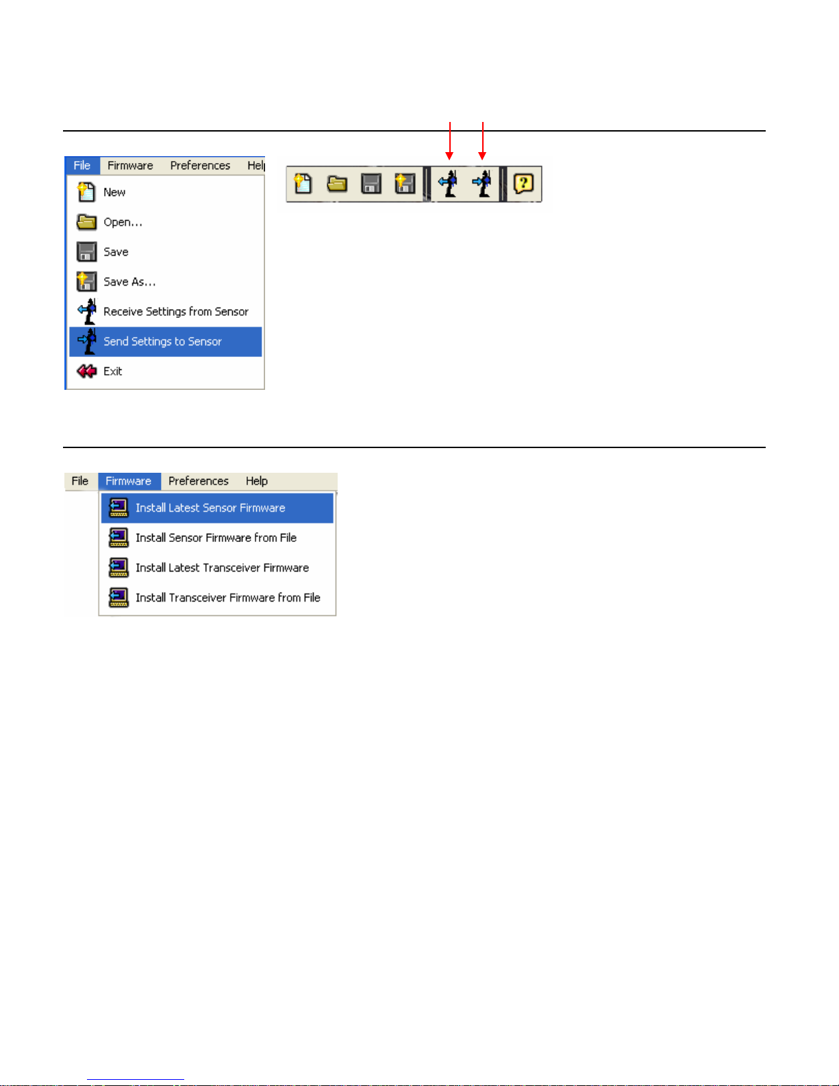
Sending Settings to the Sensor
You can send your settings to the Se nsor by choosing the File
menu and then choosing Send Settings to Sensor. You can
also sen d y ou r settin gs by ch oosin g the Send Se t ti ngs t o
Senso r toolbar butt on. If you forget to send your settings to the
sensor aft e r editing them, the Digital RC Desktop will prompt you
to send y our set tin gs on ex it.
Installing Sensor Firmware
To install new Sensor Fir mware, choose the Firm ware
menu and then choose Ins tall L a te st Firm wa r e . To
pick the file to use , ch oose In s ta ll F ir m wa re from
File.
78
Page 82

Specifications
* Specifications subject to change without notice.
Sensor Controller
Radi o Type: digital spread spectrum 2.4Ghz
Radi o Mode: direct sequence spread spectrum
Range: 1000ft. (approximate)
Frame Rate: 100 frames per second
Latency: 1 0 mi lli secon d max, 5 m s typi cal
Dimensions: 30 0m m x 13 9m m x 12 5m m (H W D )
Weig h t (w /Batteries): 674g
Servo Cha nnels: 4
Rechargeable Batteries: NiMH (incl uded)
Charger: included
Model Memory : 8 named, custom graphi cs and sound
Controller Battery Voltage Monitor: gr aphic and real-
time
Car Battery Voltage Monitor: graphi c and real-time
Ti mers: operation and lap timers
Trims: adjustabl e trim s and sub-tri m s
Controls: dual rate, endpoints, exponential, mixi ng
and servo speed adjust on all channels
Anti-Lock: brake anti -lock with cycle, delay, and depth
Idle Up: yes
Speaker: .75” w/headphone jack
Audio: programmable WAV file audio and tones
Ta c tile Alarm: pr ogr a m mab l e v ibr at or
Display: movable bac klit monoc hrome LCD
Resolution: 128 x 64 pixels
Auto Modes: aut o d is play and display on ly
Presets: fail safe and autostart
Telemetry: 3 channels of real time telemetry
Tel emetry Sens ors: speed, temperature and battery
Servos Supported: any com bination of analog and
digital
Left-Han d ed Op eration : yes (user modifiable)
PC Conne ctivi ty: USB serial fo r c ustom ization ,
analysis and updates
Antenna: fixed 3” antenna
Architecture: software upgradeable
Transceiver
Dimensions: 47. 7 x 30.2 x 19 mm
Weight: 34g (including antenna)
Antenna l ength: 22.8cm
Antenna thickness: 1.8mm
79
Page 83
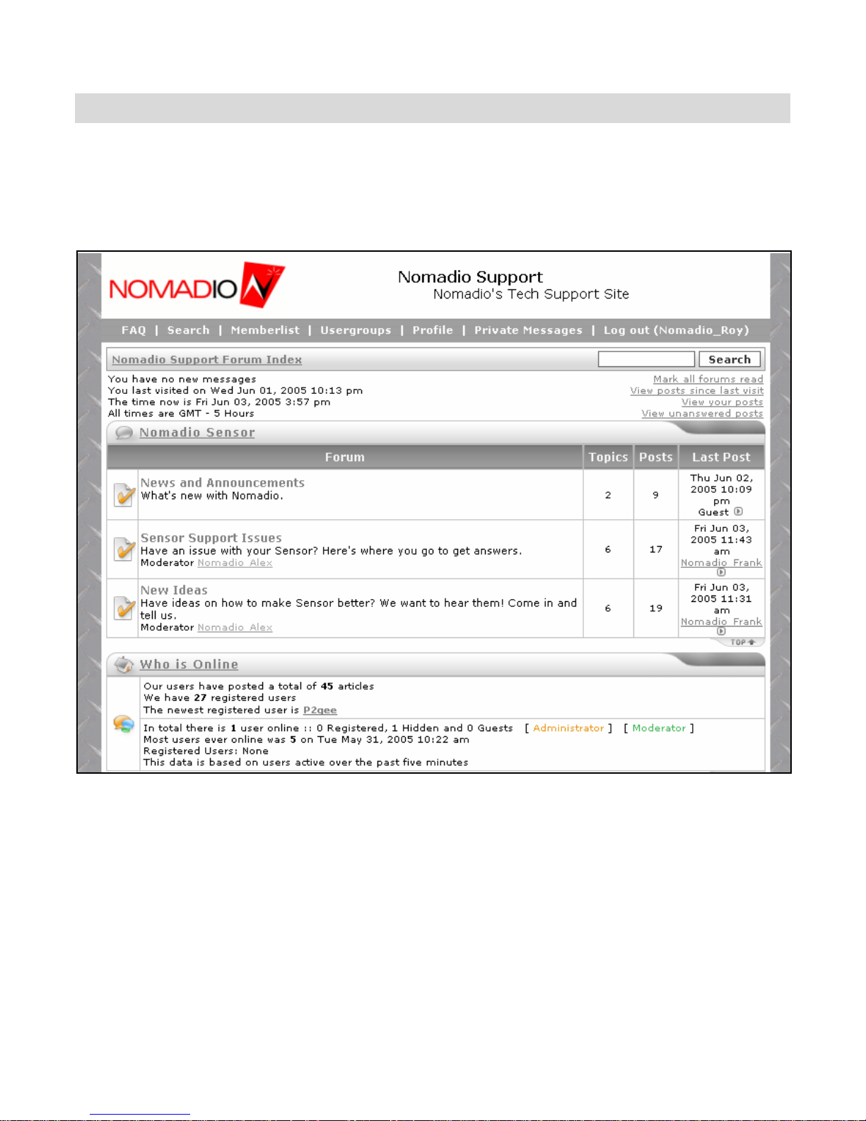
Support
Nomadio is committed to pro viding the best suppo rt in the RC market for it s products. If you
ha v e an y issues with your Sen sor, please visit our support website at
http://support.nomadio.net
Ther e you will find a wealth o f kn o wledge fr om other Sens or user s as well as Noma dio’s
support staff. Should you ne ed to contact Nomadio directly web support staff will give you the
inf orm ation necessary to get y ou runnin g.
80
Page 84

Nomadio 3 Year Limited Warranty
Warranty Coverage
Nomadio's warranty obligations are limited to the terms set forth below:
Noma dio, as defined be low, warr ants this Nomadio-branded hardware product aga inst defe cts in mate r ials and
wo rkmanship under normal use f or a peri od of THREE (3) YEARS from t he date of retail purcha se by the original
e nd-user purchaser ("Warranty Period"). If a hardware defect arises and a va lid cl aim is received within t he
Warranty Period, at its option, Nomadio will either (1) repair the hardware defect at no charge, using new or
re furbished repla cement parts, or ( 2) e xchange t h e product with a product that is ne w or which has been
ma nufactured fr om new or serviceabl e used part s and is at least functi onally equivalent to the ori ginal product, or
(3) refund the purchase price of the product. Noma dio may request that you replace defective parts wi th new or
refurbished user-installable parts that Nomadio provides in fulfillment of its warranty obligation. A replacement
product or part, including a user-installable part that has been installed in accordance with instructions provided
by Nomadio, assumes the remaining wa r ranty of the origi nal product or ninety (9 0) days f r om the date of
re placement or repa ir, whichever provides longer coverage for you. When a product or part is exchanged, any
repl acement item becomes your property and the replaced i tem becomes Nomadio's property. Part s pro vided by
Nomadio in fulfillment of its warranty obligation must be used in products for which warranty service is claimed.
When a ref und is given, the product for which the ref und is provi ded must be returned to Noma dio and become s
Nomadi o's property.
Exclusions and Limitations
This L imite d Warranty appli es only to hardware produ cts manufa ctured by or for Nomadio t hat can be ide ntifie d
by the "Nomadio" trademark, trade name, or logo affixed to them. The Limited Warranty does not apply to any
non-Nomadio hardware products or any software, even if packa ged or sold with Nomadio hardware.
Ma nufacturers, suppli ers, or publishers, other t han Nomadio, ma y provide their own warrantie s to the end user
purchaser, but N omadio, in so fa r as permitte d by la w, provides their products "as is" . Sof tware distribute d by
Nomadio with or without the Nomadio brand name (including, but not limited to system software) is not covered
under this Limited Warrant y. Refer to the licensing agreement accompanying the software for details of your
rights with respect to its use.
Nomadio does not warrant that the operation of the product will be uninterrupted or error-free. Nomadio is not
responsible for damage arising from failure to follow instructions relating to the product's use.
This warranty does not a pply: (a) to da mage caused by use with non-Nomadio products; (b) t o damage c aused
by accident , abuse, misuse, flood, f ire, earthquake or other externa l causes; (c) to dama ge caused by operati ng
the pr oduct outside the pe rmitted or i n tended uses described by Nomadio; (d) to damage cause d by se rvi ce
(including upgrade s and ex pansions) performed by anyone who is not a represe ntative of Noma dio or an
Nomadio Authorized Service Provi der; (e) to a product or pa rt that has been modified to significantly alter
functionality or capability without the written permission of Nomadio; (f) to consumable parts, such as batteries,
unl ess damage has occurred due to a defect i n materials or workmanship; or (g) if any Nomadio se rial number
ha s been removed or defa c ed.
TO THE EXTENT PERMITTED BY LAW, THIS WARRANTY AND REMEDIES SET FORTH ABOVE ARE EXCLUSIVE
AND IN LIEU OF ALL OTHER WARRANTIES, REMEDIES AND CONDITIONS, WHETHER OR AL OR WRITTEN,
STATUTORY, EXPRESS OR I MPLIED. AS PERMITTED BY APPLICABLE LAW, NOMAD IO SPECIFICALL Y DISCLAIMS
ANY AND ALL STATUTORY OR IMPLIED WARRANT IES, IN CLUDING, W IT HOUT LIMITATION, WARRANTIES OF
M ER C HAN T ABIL I TY , FI T N E S S F OR A P AR T I CU L AR P URP OSE AND W AR RANT I E S A GAI N S T HI DD EN OR LAT E N T
DEFECTS. IF NOMADIO CAN NOT LAWFULLY DISCLAIM STATUTORY OR IMPLIED WARRANTIES THEN TO THE
EXTENT PERMITTED BY LAW, ALL SUCH WARRANTIES SH ALL BE LIMI TED IN DURATION TO THE D URATION OF
THIS EXPRESS WARRANTY AND TO REPAIR OR REPLACEMENT SERVICE AS DETERMINED BY NOMADIO IN ITS
SOLE DISCRETION. No Nomadio reseller, agent, or employee is authorized to make any modification, extension,
or addition to this warranty.
81
Page 85

EX CEPT AS PROVIDED IN THIS WARRANTY AND T O TH E EXTENT PERMITTED BY LAW, NOM ADIO I S NOT
RE SPONSIBLE F OR DIRECT, SPECIAL, IN CIDENTAL OR C ONSEQUENTIAL DAM AGES RESULTING FROM ANY
BREACH OF WARRANTY OR CONDITION, OR UNDER ANY OTHER LEGAL THEORY, INCLUDING BUT NOT
LIM I TED TO LOSS OF USE; LO SS OF REVENUE; LOSS OF ACTUAL OR AN TICIPATED PROFITS (INCLUDING LOSS
OF PROFITS ON CONTRACTS); L OSS OF THE USE OF MONEY; LOSS OF ANTICIPATED SAVINGS; LOSS OF
BUSINESS; LOSS OF OPPORTUNITY; LOSS OF GOOD WILL; LOSS OF REPUT ATION; LOSS OF, DAMAGE TO OR
CORRUPTION OF DATA; OR ANY IN DIRECT OR CONSEQUENTIAL LOSS OR DAMA GE HO WSOEVER CAU SED
INCLUDING THE REPLACEMENT OF EQUIPMENT AND PROP ERTY, ANY COSTS O F R ECOV ERING , PROGRAMMING,
OR R EPROD UCI N G A NY PROGRAM OR D AT A S T OR E D OR US E D WI T H N OMADIO P ROD U CTS AN D ANY F AI L UR E
TO M AINT AIN THE CONFIDENTIALITY OF DATA ST ORED ON THE PR ODU CT. THE FOREGOING LIMITAT ION
SHALL NOT APPLY TO DEAT H OR PERSONAL INJURY CLAIMS . NOMADIO DISCLAIMS ANY REPRESENTATION
THAT IT WILL BE ABLE TO REPAIR ANY PRODUCT UN DER THIS WARRANTY OR MAKE A PR OD UCT EX C HANGE
WITHOUT RISK TO OR LOSS OF THE PROGRAMS OR DATA.
Consumer Protection Laws
FOR CONSUME RS WHO ARE COVERE D BY CONS UMER PROTECTION LAWS OR R EGULATIONS IN THEIR
COUNTRY OF PURCHASE OR, IF DIFFEREN T, THEIR COUNTRY OF RESIDENCE, THE BENEFITS CON FERRED BY
THIS W ARRANTY ARE IN ADDI TION TO ALL RIGHTS AND REMEDIES CONVEYED BY SUCH CONSUMER
PROTECTION LAWS AND REGULATIONS. Some countrie s, states and pro vi nces do not allow the exclusion or
limitation of incidental or consequential damages or exclusions or limitations on the duration of implied warranties
or conditions, so the above limitations or exclusions may not appl y to you. This warranty gives you specific legal
ri ghts, and you may al so have other rights tha t vary by country, stat e or province. This L imite d Warranty is
governed by and c onstrued under the la ws of the c ountry in which the product purc hase took place. N omadio,
the warrantor under this Limited Warra nty, is identified at the end of this document according to the country or
re gion in whi ch the product purchase took pla c e.
Obtaining Warranty Service
Please access a nd review the online help re sources referred to in the docume ntation accompanying thi s hardware
product before requesting warranty service. If the product is still not functioning properly after making use of
these resources, please contact the Nomadio representatives or, if applicable, a Nomadio Authorized Service
Provider located using the information provided in the documentation. An Nomadio representative or Nomadio
Authorized Service Provider will help determine whether your product requires service and, if it does, will inform
you how Nomadio will provide it. Nomadio or its Nomadio Authorized Service Providers will provide wa rranty
service on products that are tendered or presented for service during the Warranty Period, as permitted by law. If
the purchaser is outside the United States, service will be limited to the options available in the country where
service is requested. Warrant y service may be restricted to the country where the product is purchased. Service
options, parts availability and response times will vary according to country. You may be responsible for shipping
and handling charges if the product cannot be serviced in the country it is in. In accordance with applicable law,
Nom adio m ay require that you furnish proof of purchase deta ils and/or comply with registration re quirement s
before receiving warranty service. Please refe r to the accom panying document ation for more deta ils on t his and
other matt ers on obtaining warranty service.
If your product is capable of storing da ta or software programs, you should make periodi c backup copie s of the
data and programs contained on the product's storage media to protect your data and as a precaution against
possible operational failures. Before you deliver your product for warranty service it is your responsibility to keep
a separate backup copy of your user data, and disable any security passwords. Repaired products will be returned
to you in factory-fresh condition. You will be responsible for reinstalling all such data and passwords. Nomadio
and its Authorized Service Providers are not liable for any damage to or loss of any data, or other information
stored on any media, or any n on-Nomadio product or part not c overed by t h is warranty. Recovery and
reinstallation of user data are not covered under this Limited Warrant y.
82
 Loading...